

Page 1

Custom Electronics Ltd
AOV Multi-zone Control Unit
Installation Document
March 2008
Version 1a
Page 2

Table of Contents
1) General overview
2) System Schematics
i. Standard auto system
ii. Auto system with break glass units
iii. Auto system with detectors
iv. Auto system combination
v. Manual Control System Combination
3) Internal layout & Fixing Details
4) PCB connections
5) Technical specification
6) Installation instructions
7) Connection Guide
8) Wiring Installations
Page 3

1) General Overview
This control unit is for use with most Automatic Opening Vents and can be used with other
equipment that requires forward/reverse voltage for closure.
The unit will operate in conjunction with most current Fire Alarm Systems operating on 24v
dc.
The unit can provide battery backup so that a constant supply is applied along with visible and
audible fault and conditional warnings at the control unit.
Modular design allows for ease of parts replacement if needed.
Basic “Fireman” control can be achieved by use of an additional special yellow call point fitted
as required by the system design.
Electrical Supply
Supply to the unit should be 240V ac 50Hz (+/-5%) and earth. The supply should be fed to
the unit via a suitably rated fused outlet, fitted adjacent to the unit. The mains supply in the
enclosure must be wired into the internal fused terminal block provided. The unit must be
earthed. It is recommended that the mains supply to the unit is fed from an independent fused
supply at the main electrical distribution panel.
Operation of main unit
With mains 240vAC connected, the unit will charge batteries where fitted via the Power
Supply PCB and will give an output of 26v DC +/-10% to the actuators when activated.
The standard system is designed to operate in automatic mode and would normally be
controlled by a Fire Alarm Control Panel or other control system to operate. The design of the
Fire Alarm System will generally control each input to the unit and determine when each
actuator output is operated or reset. Full reset is effected at the Fire Alarm Control Panel at
which time the unit will reverse the polarity of the outputs and care must be taken that any
equipment connected will not be damaged by this operation.
Note: When reset is effected there will be timed reverse polarity output irrespective of
whether a trigger input from a Fire Panel or other device is present or not.
(The purpose of the timed reset is to prevent instances or repeat opening and closing when
trying to reset the Fire Control Panel. This happens when smoke is still present in an
activated smoke detector)
This unit also has a fault-monitoring relay on the battery charger PCB. The relay is energised
when the unit is operating under normal (fault free) conditions and gives a set of voltage free
contacts at the ‘Fault Relay Output’.
The relay will operate in tandem with any fault on the power supply unit (see section 6. for
PSU fault information). These contacts can be used to signal faults to a remote monitoring
system, control a remote indicator or audible unit if required or be interconnected to a Fire
Alarm Control Panel to report a fault.
Page 4

2) i Standard Auto System
Page 5

2) ii Auto system with break glass units
Page 6

2) iii Auto system with detectors
Page 7
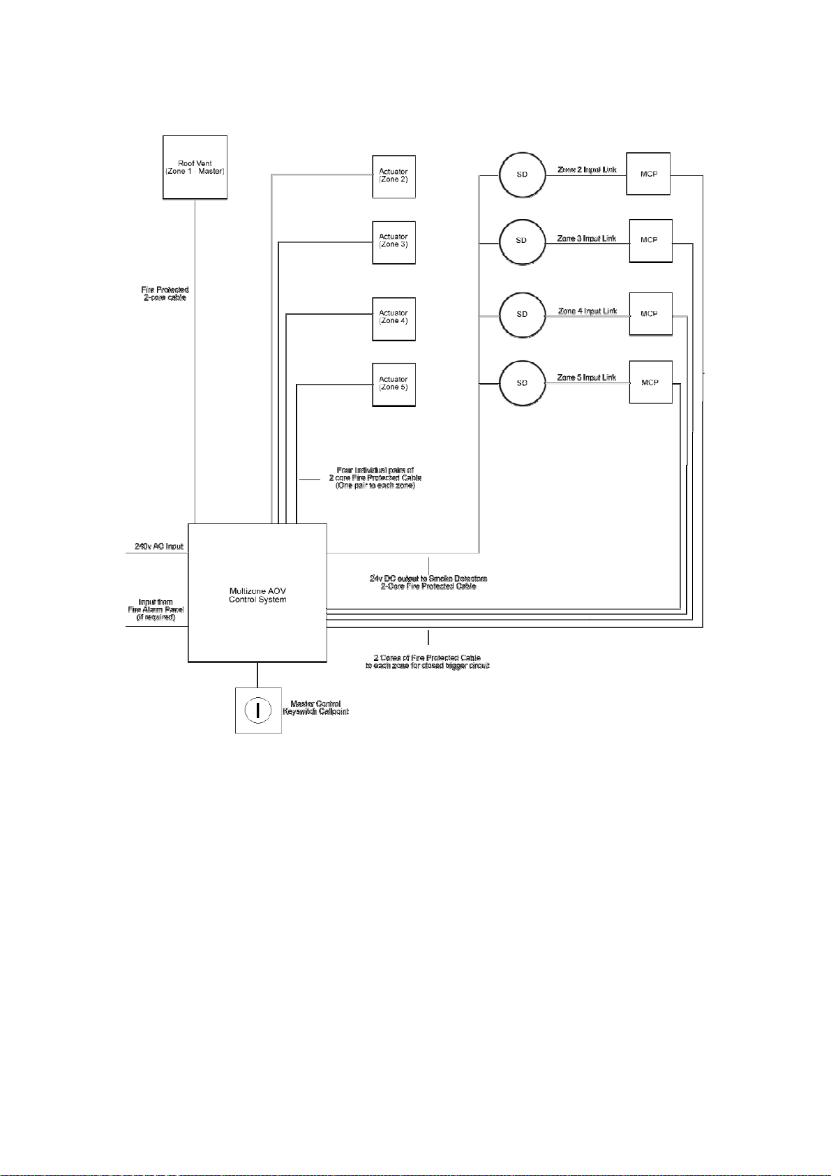
2) iv Auto system combination
Page 8
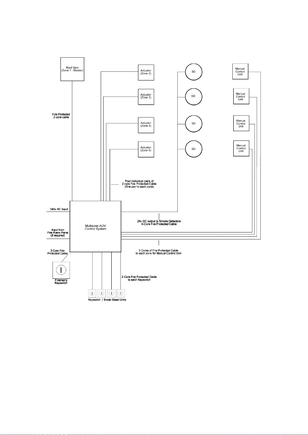
2) v Manual Control System Combination
Page 9
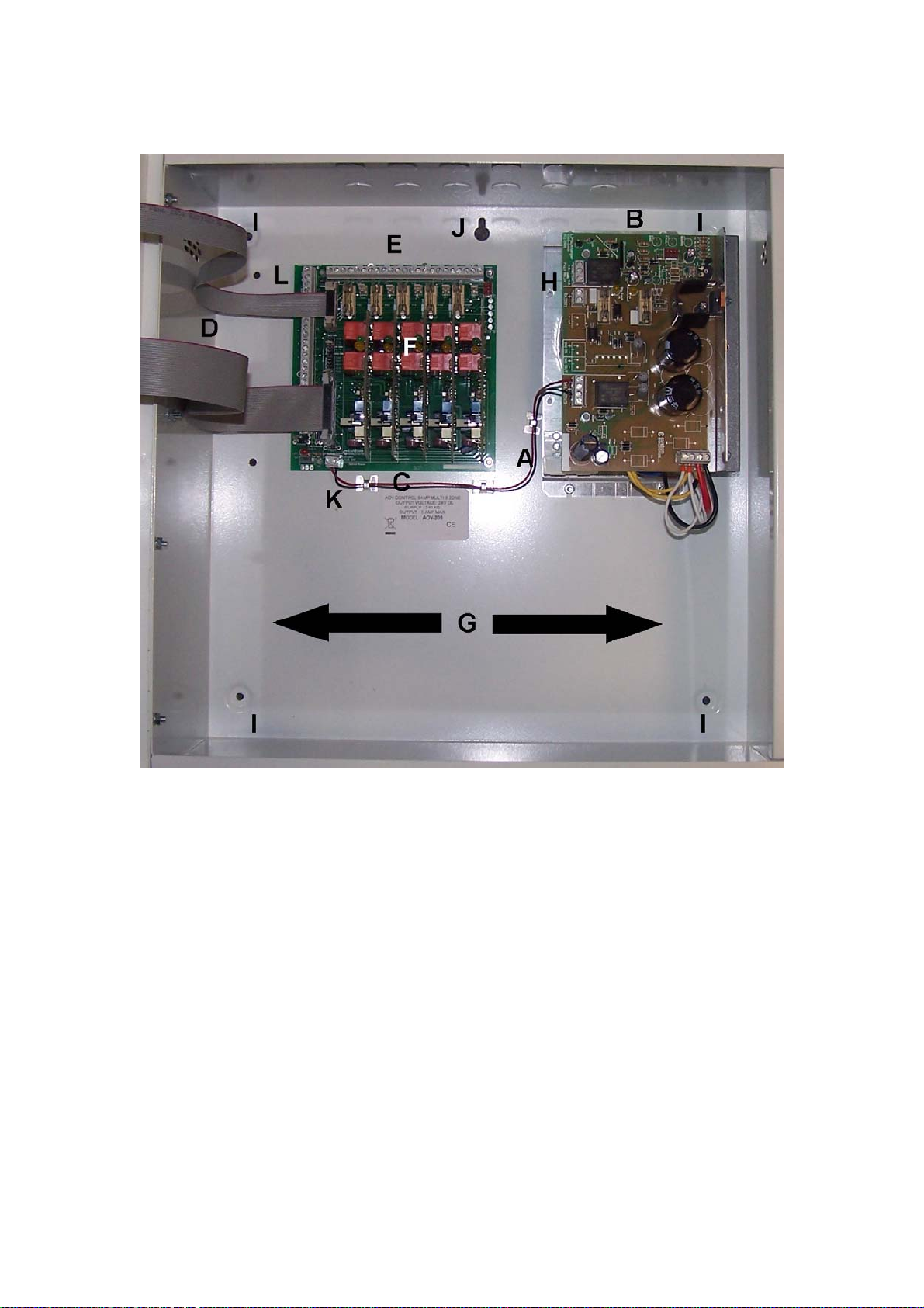
3) Internal Layout and Fixing Details
A - Mains Input
B – Power Supply (1 to 30 amp)
C – AOV Main Board
D – Indicator Connections to Front Panel
E – Actuator and Link Outputs
F – Zone Cards
G – Battery Space
H – Battery and Fault Relay Outputs
I – Fixing Holes
J – Keyhole
K – Output to Additional Zones
L – 24 v Outputs
Page 10
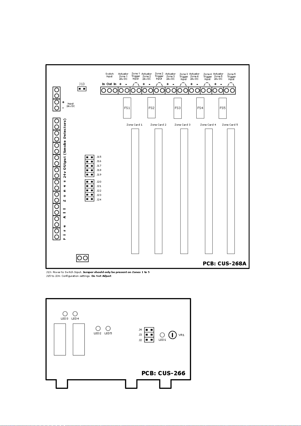
4) PCB Connections
Diag 1. Motherboard Layout
Diag. 2 Zone Card Layout
Page 11

5) Technical Specification
Power Supply Unit 5 Amp / 10 Amp
Input Supply 240v AC (+/- 10%) 50/60Hz
Input Fuse 1 - 10 Zone 5Amp, 25mm UK Type quick blow.
11 Zones + 13 Amp, 25mm UK Type quick blow.
Power Supply Unit Outputs
Voltage Load: 24v DC (+/- 5%)
Battery Charger: 27.6v DC
Load Zones 1 -5. 1 Amp single output as standard
Battery Charge: 1 Amp maximum
Fuses
Input to PCB Fuse no. FS4. 5 Amp 20mm x 5mm quick blow.
Load Output Fuse no. FS2. 3 Amp Single output as standard
20mm x 5mm quick blow
Battery Fuse no. FS1. 3 Amp 20m x 5mm quick blow.
Deep discharge protection is a feature on all models. This will cut off the battery supply to the load at 18v.
Standby Batteries
Capacity Up to 17Ah
Types 2 x 12v sealed lead acid batteries from Yuasa or other similar manufacturers.
Max. charge current 1 Amp
Max load output current 5 Amp
Quiescent standby drain xxmA @ 24v DC
Note: two 12v Batteries are required. It is important that both batteries are the same size and of the same age and cond ition to
give the maximum performance.
Indicators
Enclosure Front Panel Green LED lit shows Mains AC supply present.
Amber LED lit shows common fault.
PCB LED2 Green – lit when
LED4 Green – lit when
LED3 Yellow – lit when
LED5 Yellow – lit when
LED6 Yellow – lit when
Fault Monitoring
Main fail LED2 and lid-card green LED out
Battery not charging LED4 green stays off
Battery short circuit LED4 green stays off
Battery missing LED 3 lights
Battery fuse blown LED 3 lights
Battery low LED 3 lights
Fault relay has a set of volt free contacts. It deactivates on any fault condition.
Operating ambient temperature range
-5°C to +45°C subject to battery operating range
Relative Humidity
95% Non-condensing (max)
Page 12
6) Installation Instructions
1.1 Environment
The units are suitable for use in most indoor environments where an IP rating of IP30 is acceptable.
1.2 Mounting
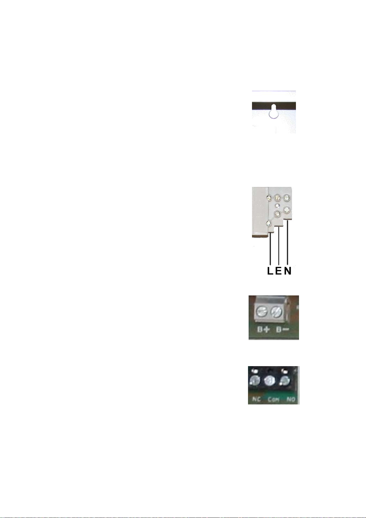
The unit should be fitted in an upright position on a solid surface using
the 4 fixing holes provided. There is a “keyhole” at the upper centre of
the enclosure which should only be used to assist in hanging the unit
whilst the rest of the fixing holes are being marked. The unit should be
located so that later access for maintenance purposes is not restricted.
There are 20mm cable entry knockouts on the top side of the enclosure
and again attention should be paid to allowing easy access to the
knockouts.
1.3 Connections
Mains: The unit connects to the AC mains supply via a fused spur unit
fitted with a 5 Amp fuse. The unit must be earthed. The spur and
wiring should have been installed in accordance with the relevant
wiring regulations and by an approved electrician. The wires should be
brought into the unit through the enclosure’s 20mm knockouts.
Appropriate glands compatible with wiring type must be used.
The mains wires from the spur must be connected to the fused mains
input block on the power supply. The polarity must be observed. The
recommended cable size for the mains wiring is 1 sq. mm minimum.
The fuse-block uses a 5Amp 25mm type fuse.
Battery: The unit is designed to charge a pair of Sealed Lead Acid
batteries wired in series to give 24V and to keep them charged for
standby duty in the event of a mains fail condition. The output
connection terminals to the battery are at the bottom edge of the PCB.
Leads are supplied for connection of the batteries and should be
connected as per diagram with red as the positive (+) and black as the
negative (-). The interconnection lead is black. The batteries should be
placed in the bottom of the enclosure.
Note: The unit also has a relay output with a single set of volt-free
contacts (com n/c n/o) for fault monitoring. This relay is permanently
energised when AC mains is present and will drop out when any of the
fault conditions are present. The volt-free connections are at the
bottom left edge of the PCB.
Page 13

7) Connection Guide
1.1 Actuator Connections
Each actuator requires a 2 core cable wired direct to the control panel and each pair must be connected to its
relevant zone via the terminal blocks numbered J28, J34, J40, J46, J52 on the zone distribution PCB. (This PCB
is numbered CUS-268A)
Refer to section 4 diagram 1 which shows the actuator connections labelled “LOAD” at the top of the PCB.
1.2 Smoke Detector Connections
Each smoke detector requires a 4 core cable which can be wired individually back to the control unit or can be
“daisy chained” in and out back to the control panel. 2 cores are required for the power (24vdc +Ve/-Ve) and 2
cores for closed circuit switching.
Refer to section 4 diagram 1 showing the connections. The detector 24Vdc supply is taken from the terminals to
the left side of the PCB labelled ‘24V output’ - observe polarity! The other 2 cores from the detector are
connected to relevant zone at terminals labelled “Link” at the top of the circuit board. As many smoke detectors
can be used as required providing a SERIES connection closed loop is created between each detector. Each
‘Link’ terminal fires its own zone actuator.
1.3 Standard Call Point – VCS-001
The standard yellow manual control point comes with “Break Glass” element.
These units require 2 core cables which are also connected to the ‘LINK’ terminal blocks in the control panel.
These can be installed as a stand alone unit on each zone or connected in SERIES with a smoke detector or
other call points.
NOTE: The LINK connection terminal blocks are 24v + positive and it is essential that no negative wire should
be applied to these terminal blocks or the power supply/AOV board will be seriously damaged.
1.4 Manual Control Unit Yellow with Open/close illuminated switches. – VCS-002
The manual control point is a feature only available with the extra manual control circuit board. For the multizone configuration the AOV system must be ordered with the “Manual Control” PCBs fitted in the unit as an exworks optional extra. The call point requires a 5 core cable.
These connections are label: Negative, Open, Close, Power LED, Manual LED.
These connections are common throughout both the manual control point and the manual control circuit board
and correct wiring MUST be observed with close attention.
1.5 Keyswitch Yellow Call Point – VCS-003 (open/close)
The keyswitch yellow manual control point is fitted with an open and close key switch.
This unit requires a 2 core cable which is also connected to the ‘LINK’ terminal blocks. They produce the same
input to the AOV board by turning the switch as a smoke detector activating. This can be installed as a stand
alone feature for each zone or connected in SERIES with the smoke detectors.
NOTE: The LINK connection terminal blocks is 24v + positive and it is essential that no negative wire should
be applied to these terminal blocks or the power supply/AOV board will be seriously damaged.
.
1.6 Keyswitch Call Point yellow – VCS-004 (auto/open/close)
The fire override call point comes with a three position key switch. These positions are AUTO, OPEN and
CLOSE. In its standard AUTO position the AOV will perform in it usual manner. If the Key is turned to OPEN,
all zones will open regardless of the state of any other trigger input connected to the system. If the key is turned
to CLOSE, all zones will close regardless of the state of any other trigger input connected to the system.
NOTE: The AOV main board includes an on board override switch to CLOSE the outputs as an aid to
commissioning and service. This is located on the lower left of the board labelled ‘Fire Override’ (SW1).
1.7 Illuminated switch Call point – VCS-005 (open/close)
• Observe 4 wires, red – positive, black – negative, blue – switch.
• Connect red and black cables to 24V outputs (- , +) J3-J7.
• Connect blue cables to upper Link terminals for individual triggering.
• Connect blue cables to left Link terminals for multiple triggering.
Further information can be obtained from the Commissioning Manual.
Page 14
8) Wiring Installation
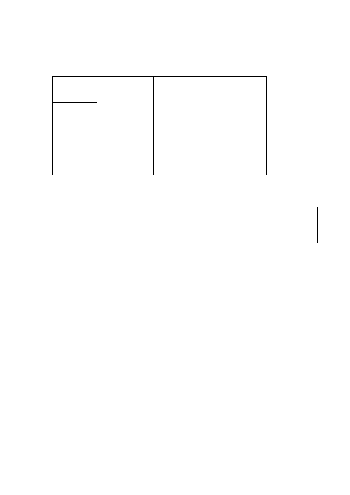
Upon installation maximum cable lengths must be adhered to, use the following table to calculate the
maximum cable lengths, taking in to account the cross section of the cables.
Cross Section 3 wire 5 wire 3 wire 5 wire 3 wire 5 wire
1.5mm2 1.5mm2 2.5mm2 2.5mm2 4mm2 6mm2
Actuator current
Amps
1 105.00m 210.00m 175.00m 350.00m 280.00m 420.00m
2 52.50m 105.00m 87.50m 175.00m 140.00m 210.00m
3 35.00m 70.00m 58.33m 116.67m 93.33m 140.00m
4 26.25m 52.50m 43.75m 87.50m 70.00m 105.00m
5 21.00m 42.00m 35.00m 70.00m 56.00m 84.00m
6 17.50m 35.00m 29.17m 58.33m 46.67m 70.00m
7 15.00m 30.00m 25.00m 50.00m 40.00m 60.00m
8 13.10m 26.20m 21.80m 43.75m 35.00m 52.50m
(For ambient temperatures of 25°C)
If the above table does not correspond to your system design the following calculations can be used for
cable length:
Maximum permissible voltage drop in the cable: 2.5V
Max. cable length = permissible voltage drop (2.5) x conductivity of copper (56) x Cable cross-sectional area (A)
Max. Actuator current total (I) x2
The cable length from the actuator to junction box should not exceed 10m,
2 wires in
parallel
2 wires in
parallel
Page 15
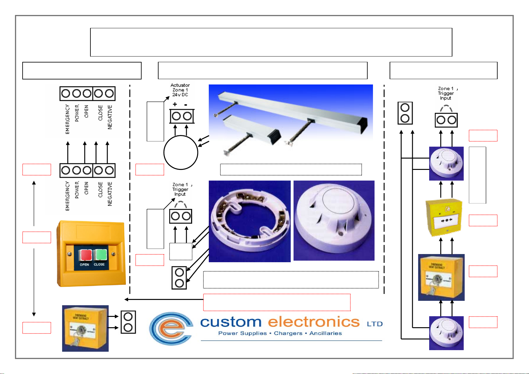
AOV Multi-zone Quick Guide Connection Sheet
AOV Manual Control Point
5 - Core
L
O
A
D
2 - Core
Actuator and Triggering Connections
M
See smoke detector wiring diagram for relay base connections.
Multiple Triggering
Power 24V
4 - Core
S
E
R
I
E
S
7 - Core
2 - Core
EM – Manual Activation Input
L
I
N
K
4 - Core
2 - Core
N/C
2 - Core
Multiple trigger inputs must be in SERIES and NORMALLY CLOSED.
Power 24V
Manual control requires key switch activation; Cable cores depend on
how many locations are required for activation switches. 5 or 7 Core.
4 - Core
Page 16

Quick guide
• Fix unit on to wall using mounting holes provided.
• Remove cable ties securing zone cards.
• Connect mains via lower power supply and switch on.
• Check all power supplies are active.
• Check all AOV boards have power.(Timers will enable upon initial
turn on).
• Install batteries to relevant power supplies – removes fault
indications on front panel.
• Install call points, smoke testers or relays to terminals J8-J12 (fire
all zones - Link).
• Install call points, smoke testers or relays to terminals
J33,J39,J42,J48,J53 (Fire zones individually - Link)
• Install actuators to ‘Load’ terminals.
Page 17

Jumper Settings
For Zone 1 to operate as a master zone the following steps must be adhered
to:
5 Zone Panel
Step 1
The following jumpers should be enabled for zone 1 to act as a master:
J16, J18, J19
Jumpers J20 – J24 configure zones 1-5 respectively to operate alongside
zone one.
E.g Jumper J23 will enable zones 2-4 to act in tandem with the master zone.
Therefore zone 5 will remain operating independently.
Step 2
Remove Jumper J29 – Note there must be no trigger input at terminal J33
(Link1).
10 Zone Panel
Step 1
The following jumpers should be enabled for zone 1 to act as a master:
Upper circuit board: J16, J18, J15
Jumpers J20 – J24 configure zones 1-5 respectively to operate alongside
zone one. If using more than 5 zones with the master insert a jumper on to
J24 to continue the master on to the lower circuit board.
Lower circuit board: J17
Jumpers J20 – J24 configure zones 6-10 respectively to operate alongside
zone one.
E.g Jumper J23 will enable zones 2-9 to act in tandem with the master zone.
Therefore zone 10 will remain operating independently.
Step 2
Remove Jumper J29 on upper circuit board (zone 1) – Note there must be no
trigger input at terminal J33 (Link1).
Step 3
Connect two cables between circuit board 1 and circuit board 2:
Cable 1: Board 1 Master Connection OUT Master Connection IN Board 2
Cable 2: Board 2 Master Connection OUT Master Connection IN Board 1
Example for AOV20-10 with zone one as a master. Once step 3 is completed:
Upper board:
J15, J16, J19, J24
Lower Board:
J17, J24.
 Loading...