

Custom Dynamics Road Glide CD-RG-TS-15-B, Road Glide CD-RG-TS-15-RAW, Road Glide CD-RG-TS-15-C Installation Instructions Manual
Custom Dynamics® Road Glide® LED Turn Signals
Installation Instructions
Questions? Call us at: 1 (800) 382-1388 M-TH 8:30AM-5:30PM / FR 9:30AM-5:30PM EST
10-2017
We thank you for purchasing the Custom Dynamics® Road Glide®
LED Turn Signals. Our products utilize the latest technology and
highest quality components to ensure you the most reliable service. We offer one of the best warranty programs in the industry
and we back our products with excellent customer support. If you
have questions before or during installation of this product please
call Custom Dynamics® at 1(800) 382-1388.
Package Contents:
- LED Turn Signal Assemblies w/ gaskets (pair)
- 5/16-18 x 3/4 Sock Head Screw (2)
- 1/4-20 x 1 Button Head Screw (2)
- Thread locker 0.5 ml (1)
- Instructions
Part Numbers:
Fits: 2015-2018 Harley-Davidson® Road Glide®, Road
Glide® Special & Road Glide® Ultra Models Including
CVO™
ATTENTION
Please read all Information below before Installation
Warning: Disconnect the negative battery cable from battery; refer to
owner’s manual. Failure to do so may result in electrical shock, injury or
fire. Secure negative battery cable away from positive side of battery and
all other positive voltage sources on vehicle.
Safety First: Make sure the bike is parked on a level surface and bike‘s
mechanical components are cool to the touch.
Notice: This product is designed and intended for use as auxiliary lighting
on motorcycles only. This product is NOT intended to replace any original
equipment lighting installed on the motorcycle and should not be used for
that purpose. This product must be wired such that it does not interfere
with any original equipment lighting.
Note: Some technical knowledge may be needed for this installation.
Consult your vehicle detailed service manual for instructions on removing
the front fairing and for electrical wiring information. Use a meter or test
light to verify the turn signals before connecting to any vehicle wiring. If
the steps contained within are beyond your skillset, do not attempt installation, contact a qualified mechanic or dealership to assist you.
Cleaning: Take special care in cleaning the finish. Never use abrasive
polishes or cleaners as these can scratch the finish.
Installation:
CD-RG-TS-15-B CD-RG-TS-15-C CD-RG-TS-15-RAW
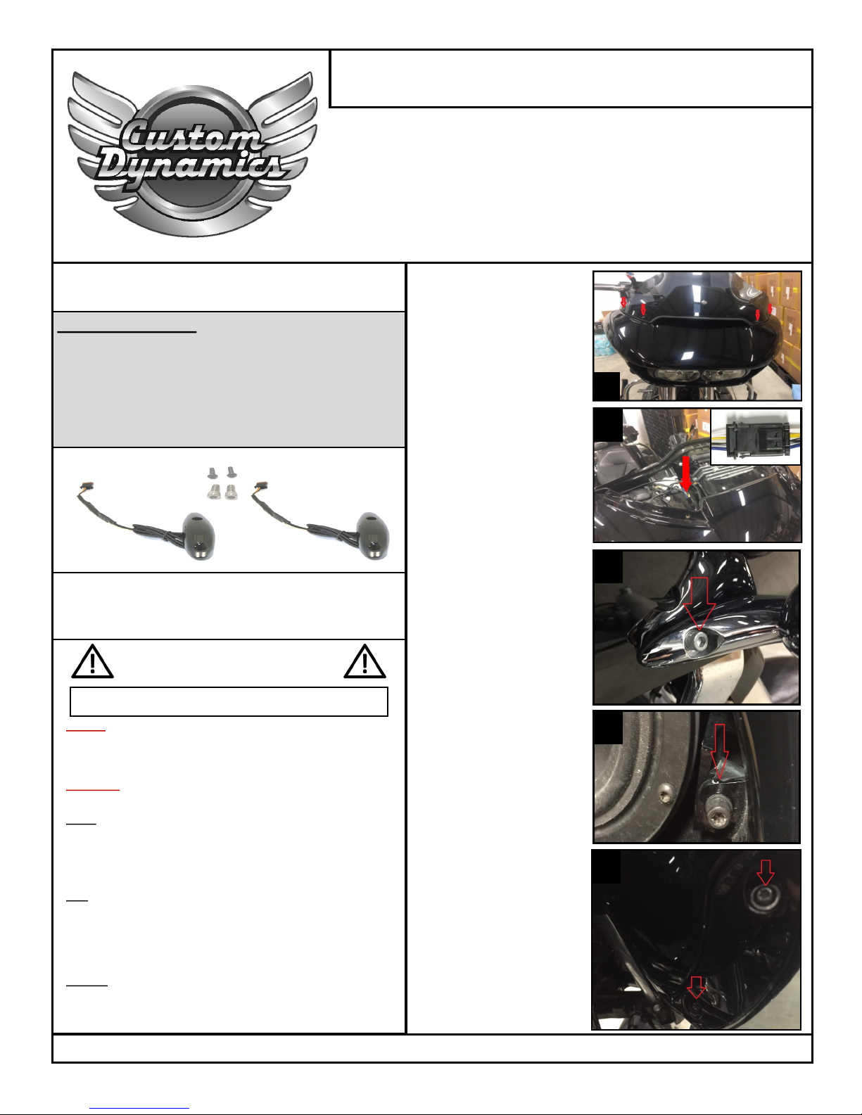
1
1. Remove the 4 stock wind-
shield bolts and remove the
windshield.
2. Remove factory vent by pull-
ing straight up on the vent.
The vent comes snapped in
place.
3. Locate and unplug the left
and right side 3 pin turn signal harness.
4. Remove the 3/16” socket
allen head bolts from the
outside of each turn signal
housing.
5. Remove both left and right
speaker grilles on the inner
fairing by prying up with a
small flat head screwdriver
between the speaker grill and
inner fairing.
6. Once the speaker grilles are
removed, locate and remove
the T-27 torx bolts in each
corner of the speaker housing.
7. Locate and remove the two
T-25 screws below each
glove box on the inner fairing
that fasten the wind deflectors and the outer fairing to
the inner fairing.
Once the bolts are removed
the outer fairing will be separated from the inner fairing.
8. Remove the outer fairing
(with OEM turn signal housings still attached) and set to
the side.
4
3
6
7

Installation Instructions - Page 2
Questions? Call us at: 1 (800) 382-1388 M-TH 8:30AM-5:30PM / FR 9:30AM-5:30PM EST
09-2016SM
9. Remove both the left and right OEM turn signal housings from
the outer fairing by removing the two ¼” allen head socket
bolts on the back side of each turn signal.
10. Install the new right front turn signal and attached gasket by
routing the wire and plug through the hole in the fairing and
through the clip.
11. Align the locating pin on the backside of the new turn signal
unit with the hole on the plastic mount. Place a drop of supplied
Loctite on threads of supplied 5/16-18 socket head screw,
tighten securely.
12. Repeat steps 10 and 11 for the left side.
13. Reinstall the outer fairing using the original hardware from
steps 6 and 7
14. Route the wires from each turn signal to the OEM connectors
(unplugged in step 3) and plug in making sure the left turn
signal is plugged into the OEM connector with a purple wire
and the right turn signal is plugged into the OEM connector
with a brown wire.
15. Place a drop of supplied thread locker on threads of supplied
1/4x20 button head screws. Install and tighten from the outside
of each turn signal.
16. Reinstall speaker grilles by applying light pressure. They
should snap into place.
17. Reinstall factory vent by snapping it into place.
18. Reinstall windshield using original hardware.
19. Perform a BCM sync by turning key on, turn 4 way hazards on,
turn key off. Allow hazards to run for 3-4 minutes. Turn Key on,
Turn Hazards off, Turn Key off.
20. Test operation of running and turn signal lights.
10
Installation (Continued):
20
 Loading...