

Page 1
ValveSentry™
USER’S MANUAL – REVISED 8/6/16
IMPORTANT! PLEASE READ CAREFULLY AND SAVE
This user’s manual contains important information about your ValveSentry™ device’s operation. If you are installing this ValveSentry™ device
for use by others, you must leave this manual—or a copy of it—with the end user.
1
CustomControls, LLC
Page 2

TABLE OF CONTENTS
Page No.
Introduction . . . . . . . . . . . . . . . . . . . . . . . . . . . . . . . . . . . . . . . . . . . . . . . . . . . .3
Basic Safety Information . . . . . . . . . . . . . . . . . . . . . . . . . . . . . . . . . . . 4
What’s in the Box? . . . . . . . . . . . . . . . . . . . . . . . . . . . . . . . . . . . . . . . . 5
Installation Instructions . . . . . . . . . . . . . . . . . . . . . . . . . . . . . . . . . . . . . . . . . . 6
Installation on a Gate Valve . . . . . . . . . . . . . . . . . . . . . . . . . . . . . . . . 7
Installation on a Ball Valve . . . . . . . . . . . . . . . . . . . . . . . . . . . . . . . . . 10
Water Sensor Placement . . . . . . . . . . . . . . . . . . . . . . . . . . . . . . . . . 11
Connecting the Controller . . . . . . . . . . . . . . . . . . . . . . . . . . . . . . . . . 12
Battery Installation (IMPORTANT NOTE TO USE 7-AAA BATTERIES) 13
Testing and Maintenance . . . . . . . . . . . . . . . . . . . . . . . . . . . . . . . . . . . . . . . . . 13
Warranty Information . . . . . . . . . . . . . . . . . . . . . . . . . . . . . . . . . . . . . . . . . . . 16
2
CustomControls, LLC
Page 3

INTRODUCTION
Thank you for purchasing the ValveSentry™ device. It is an important component of your home security system
protecting against damage from water leaks. This device is suitable to control one valve by turning it on or off
when the sensor detects moisture. This device has a one year limited warranty (see below for details). Please take
a few minutes to thoroughly read this user’s guide, and save for future reference. The more familiar you are with
the information it contains, the easier you will find it to install, operate and maintain your device properly which
ultimately means greater security and peace of mind. If you have any questions about the operation of installation
of your device, please call our consumer hotline at 508-320-9082.
3
CustomControls, LLC
Page 4

BASIC SAFETY INFORMATION
IMPORTANT!
• “DANGER,” “WARNING,” and “CAUTION” alert you to important operating instructions or to potentially hazardous situations. Pay special
attention to these items.
• DANGER: The ValveSentry™ device is powerful. It has considerable torque allowing it to open and shut your valve. THEREFORE ALWAYS KEEP
YOUR HANDS AND FINGERS AWAY FROM THE DEVICE while it is powered. If your hand or finger gets caught on a valve or is between the valve
and a pipe, wall or other object while a valve is opening or closing, it could cause injury. That is why you should always unplug and remove
the batteries from the unit prior to installing, adjusting or touching it. Remember that you can always immediately shut down the unit by
pressing the “stop” button on the controller.
• WARNING: Before you turn off a water source. Be aware of any consequences that can result from your valve being turned off by the
ValveSentry™ device before installing it. For example, some heating systems can be damaged if water is cut off for any length of time.
CustomControls LLC is not responsible for such damage. Therefore, please deploy the ValveSentry™ device in a thoughtful manner.
• CAUTION: The ValveSentry™ device has limitations. This ValveSentry™ device is not foolproof and is not warranted to protect lives and
property from water damage and associated hazards such as electric shock. The ValveSentry™ device is not a substitute for insurance.
Homeowners and renters should insure their lives and property. In addition, it is possible, although unlikely, for the ValveSentry™ device to
fail at any time. For this reason you must test the ValveSentry™ device monthly, assure it has fresh batteries and is working properly. It is
recommended that you replace it with a new ValveSentry™ device every 5 years.
• CAUTION: The ValveSentry™ device is NOT a solution for a “stuck” or frozen valve. The valve that is being protected must be in good
working order for the ValveSentry™ device to be effective. If you cannot turn off your valve using normal hand strength, the ValveSentry™
device cannot turn off your valve.
BATTERIES: THE VALVESENTRY BATTERY HOLDER INCLUDES EITHER A SHORT BAR OR A DUMMY BATTERY.
DO NOT REPLACE THIS WITH A REGULAR BATTERY. DOING SO WILL DESTROY THE VALVESENTRY. THE
VALVESENTRY ONLY REQUIRES 7 AAA BATTERIES. TEST THE VALVE SENTRY TO MAKE SURE THAT IT WORKS ON
BATTERY POWER EVERY THREE MONTHS.
4
CustomControls, LLC
Page 5
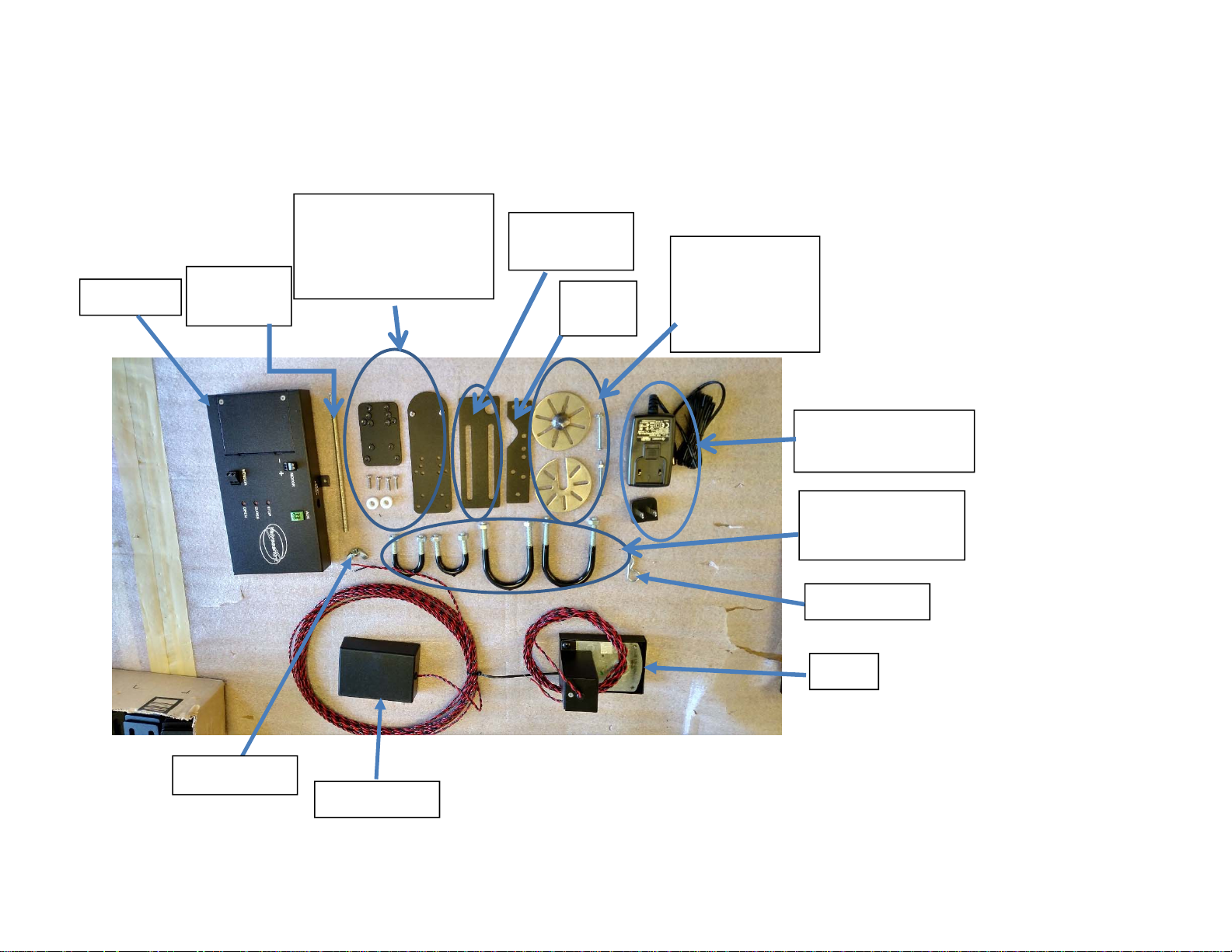
What’s in the Box?
Controller
Threaded
Rod
Ball Valve handle mount
and screws (comes
pre-assembled.
See page 10.
Pipe Mount
Bracket
Motor
Bracket
Gate Valve
handle mount
(top and bottom discs)
and 3 screws
(2 shown)
Power Supply and
detachable plug
U Clamps to mount
pipe mount bracket
Cotter Pin
Motor
Wing Nut
Water Sensor
5
CustomControls, LLC
Page 6

INSTALLATION INSTRUCTIONS
The following installation instructions should allow you to install the ValveSentry
device in a short period of time. You will need a Phillips head screw driver and a
wrench to tighten the bolts on the U-clamps.
tm
6
CustomControls, LLC
Page 7
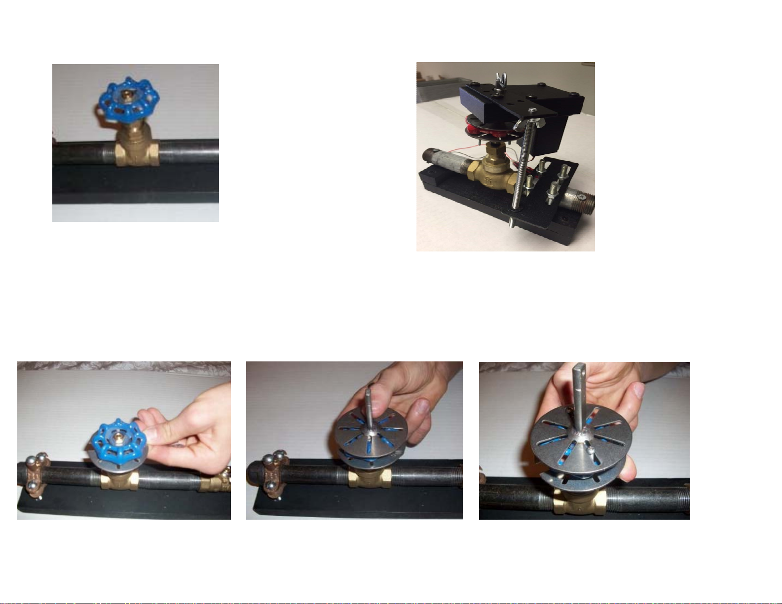
How to mount the ValveSentry
Gate Valve
tm
Device to a Gate Valve
Figure A: What it should look when properly installed
Step 1: Place bottom disc under gate
valve handle.
Step 2: Place top disc on top of Gate
valve handle centering the shaft
™over the center of the handle and
lining up at least two slots to slip #4
screws through.
7
Step 3: Place the three stainless
steel screws through slots on upper
and lower disc with gate valve
handle sandwiched in between.
CustomControls, LLC
Page 8
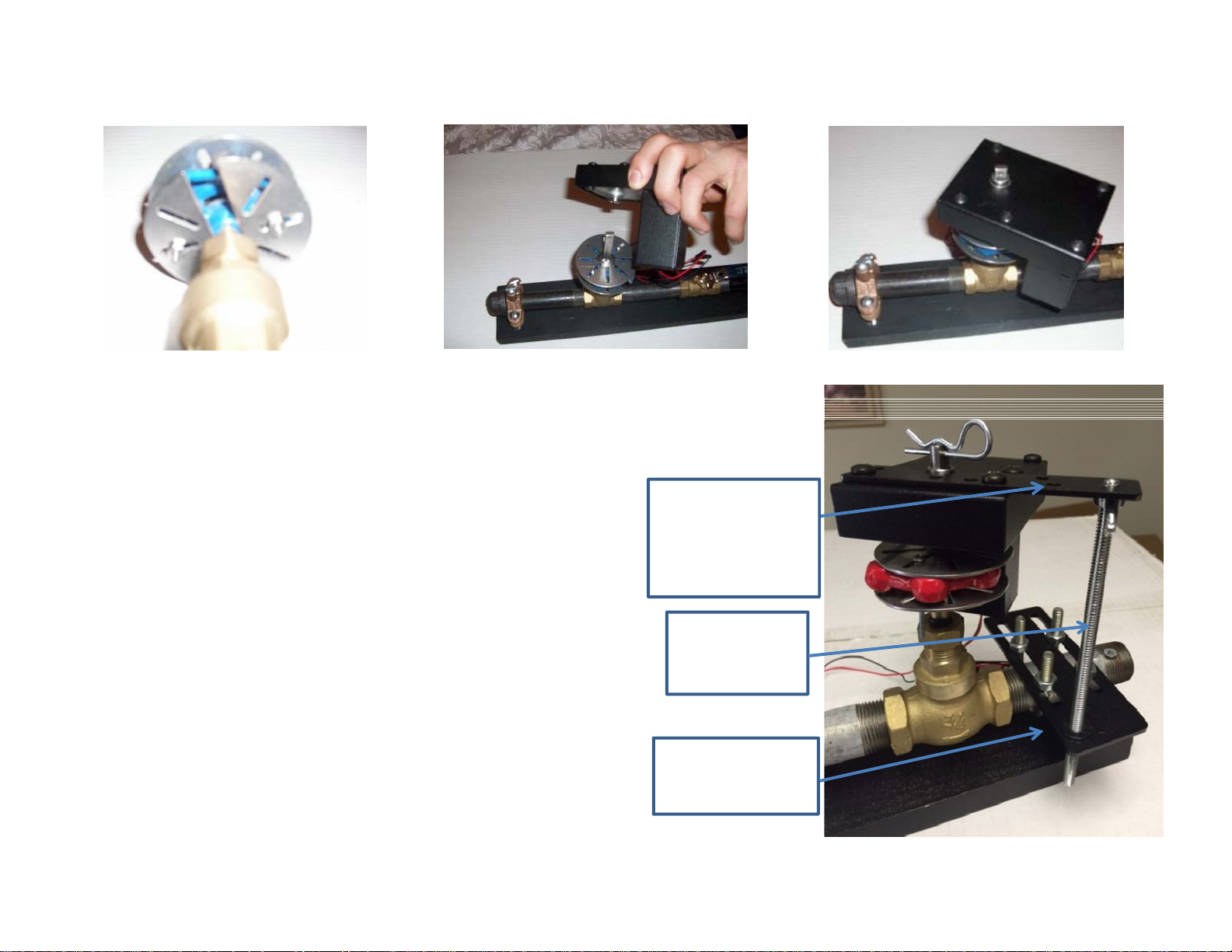
Step 4: Twist on and tighten #4 lock
nuts to # 4 screws on bottom disc.
Step 6: Install motor bracket onto motor. There are numerous locations
to mount the motor mount bracket. Install so that the threaded rod
(Step 7) will line up with the plastic bushing hole in pipe mount bracket
after the pipe mount bracket is installed (Step 8).
The motor mount bracket contains a number of holes and is shaped so
that it can be mounted to the right side, left side, front or the back of
the motor. Mounting on the top surface, if possible, is desirable for
most installations. Choose the position that works best. Remove the
selected screws from motor, install the bracket, and re-tighten screws.
NOTE: The bracket is mounted on top of motor in picture.
Step 5: Place motor over top gate mount disc such that motor
drive lines up with the shaft on the top gate mount disc.
Motor Mount
Bracket
Threaded
Step 7: Screw in threaded rod through appropriate hole on motor
mounting bracket such that the rod extends down to the plastic
bushing hole in pipe mount bracket. Install wing nut on threaded rod
under the motor mount bracket and tighten.
8
Rod
Pipe Mount
Bracket
CustomControls, LLC
Page 9
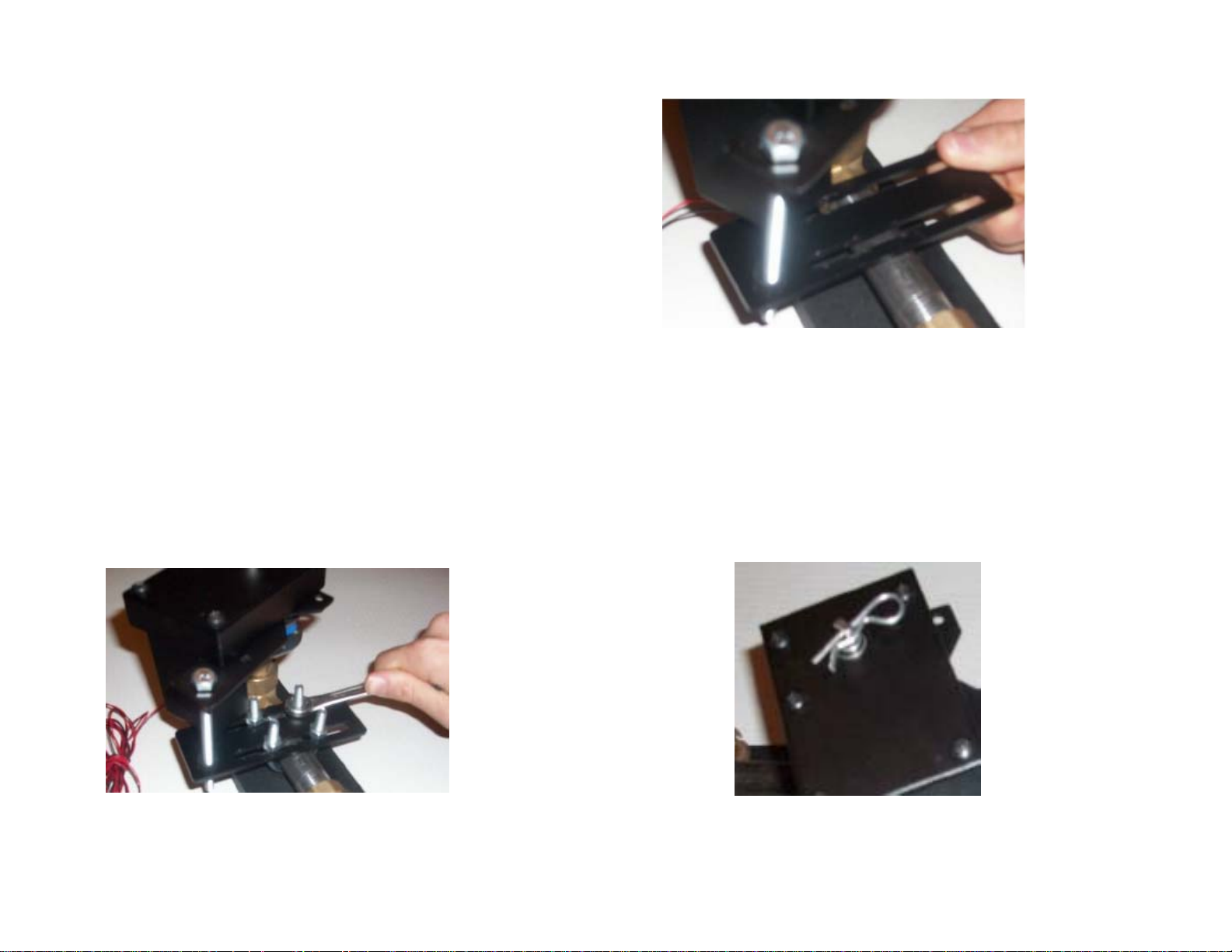
Step 8: Select appropriate location to install the pipe
mount bracket. The bracket may be installed on either
side of the valve in the desired location. Install pipe
mount bracket and motor mount bracket in desired
positions so that the threaded rod will pass through
plastic bushing hole in pipe mount bracket.
Step 9: Install proper size U-bolts around
pipe and through the slots on the pipe
mount bracket. Use smallest U-bolts that
will fit around the pipe. Fasten pipe mount
bracket to pipe.
Step 10: Slip cotter pin through
hole on top of shaft to secure
motor to valve handle.
9
CustomControls, LLC
Page 10
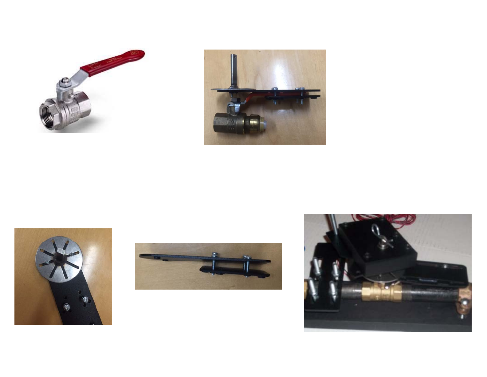
How to mount the ValveSentry
Ball Valve
Step 1: Install the top disc on
top center of Ball Valve Handle
Mount
tm
device to a ball valve
Figure B: What handle bracket should look like when properly installed.
Step 2: Slide the assembly as shown below over
the valve handle so that the top disc shaft lines
up with the valve’s spindle as shown in the
picture above.
Step 3: Refer to Gate Valve mount steps 5-10 to mount
motor bracket to motor, pipe mount bracket to pipe,
U-bolts and then slip Motor over top disc axel such
that threaded rod will pass through plastic bushing
hole in pipe mount bracket.
You will see that there are a variety of locations
for screws. Change the screw locations as
required to make them as close to the sides of
the valve handle as possible. This provides a
snug fit.
10
CustomControls, LLC
Page 11
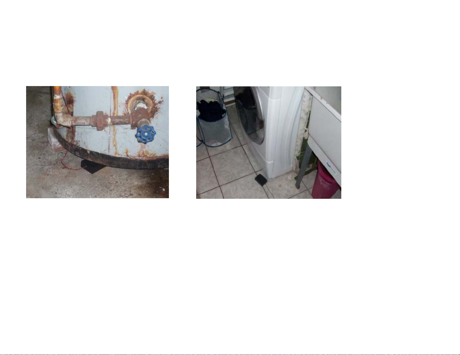
Place Water Sensor in location to be monitored
Multiple water sensors can be used
Route wires to Controller being careful not to short or break them
11
CustomControls, LLC
Page 12
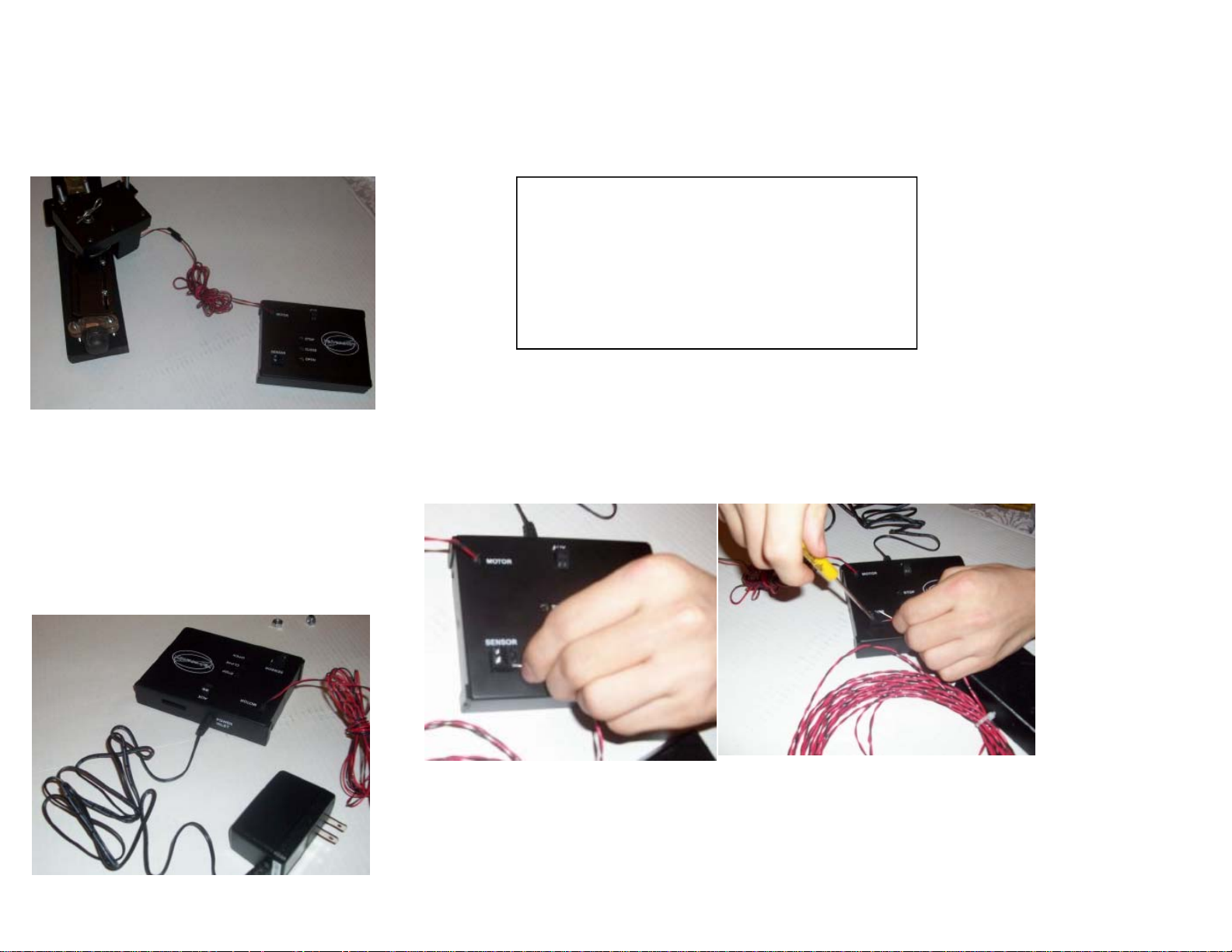
Connecting Controller
Step 1: Depending upon your model, connect Motor to Controller by connecting the red and black wires from the
motor to positive and negative terminals on the Controller.
Step 2: Plug Power Supply into connector
on Controller. Note the Power Supply may
look differently than shown below. Plug in
the Power Supply to a 120 Volt properly
grounded power outlet.
NOTE: Under rare circumstances the motor needs to
be mounted upside down on the disc shaft to fit the
installation. You can do this as long as you reverse the
connections of the motor wires to the controller by
placing the red wire on the negative terminal and the
black wire on the positive terminal.
Step 3: Connect wires from water sensor to water sensor terminals on
Controller. The polarity or wires is not important. Multiple sensors can be
connected in polarity.
12
CustomControls, LLC
Page 13

Battery Installation: (7-AAA ONLY)
The ValveSentry Device will operate with the batteries installed. THEREFORE
INSTALL BATTERIES AS YOUR LAST STEP of the installation procedure
• Open the battery door by unscrewing the small screw on the side of the controller. Being careful not
to break any wires, install seven AAA batteries in the open battery compartments. You will see that one battery
compartment is occupied by a shorting bar or wire. Do not remove the shorting bar or wire and do not attempt
to install a battery in that spot. If you install 8 AAA batteries you will damage the controller.
DANGER: The ValveSentry™ device is powerful. It has considerable torque allowing it to open and shut your valve. THEREFORE ALWAYS KEEP
YOUR HANDS AND FINGERS AWAY FROM THE DEVICE while it is powered. If your hand or finger gets caught on a valve or is between the valve
and a pipe, wall or other object while a valve is opening or closing, it could cause injury. That is why you should always unplug and remove the
batteries from the unit prior to installing, adjusting or touching it. Remember that you can always immediately shut down the unit by pressing the
“stop” button on the controller.
TESTING & MAINTENANCE
CAUTION: SEMIANNUAL TESTING
Test the ValveSentry™ device and the valve it is attached to at least twice a year. As a simple way to remember this, we recommend that
you test it when Daylight Savings time started in March and again when it ends in November.
If the ValveSentry™ device ever fails to test correctly after taking the actions recommended in “Trouble Shooting” below, have it replaced
immediately! If the ValveSentry™ device is not working properly; it cannot react to a water emergency. Similarly, if your valve does not
turn on or off, it must be serviced in order for the ValveSentry™ device to operate.
13
CustomControls, LLC
Page 14

TESTING PROCEDURE.
1. Test the Valve Sentry Controller and Motor: Push the open, close and stop buttons on the controller and making sure that the ValveSentry
responds correctly.
2. Test the water sensor: Touch the water sensor with a wet sponge or paper towel. Hold the wet sponge or paper towel to the water sensor
for five seconds. This should close the valve that the ValveSentry is attached to. It will take roughly three to five seconds to respond. Use
the open button on the Controller to open the valve again. Repeat with each water sensor if you have more than one.
3. Test for battery Operation: Unplug the ValveSentry’s power supply and perform test 1 and 2 above. The ValveSentry should work in the
same way except that the motor may rotate at a slightly different speed.
If the ValveSentry™ device does not test properly:
1. Make sure that the device is plugged into a working power outlet and/or has fresh batteries and that they are installed correctly.
2. Using your hand, make sure the Valve that the ValveSentry is attached to opens and closes using normal force. A rusted or jammed
valve cannot be operated by the ValveSentry™ device.
3. If the Valve functions properly, perform step 1 of the test procedure above. The ValveSentry should close and open the valve that it
is attached to.
a. If this does not work, then we know the problem is with the controller or motor. Proceed to step 4.
b. If this works, then we know that the problem is with either the water sensor or the wire connection if your unit has a wired
connection.
i. If the sensor is connected by wire, check the wire to make sure that it is not cut or damaged.
ii. Make sure the wires are connected to the Controller, (See Step 3 under “Connecting Controller” above).
If i-ii checks out, then you have a malfunctioning Sensor that needs to be replaced.
4. Be sure the ValveSentry™ Controller and motor are connected properly as discussed in “Connecting the Controller” section above.
5. If after trying the above the device still does not operate, service or replace the device.
• DO NOT try fixing the ValveSentry™ device yourself – this will void your warranty! If the ValveSentry™ device is still not operating properly,
and it is still under warranty, please see "How to Obtain Warranty Service" in the Limited Warranty.
*For a list of acceptable replacement batteries, see “Regular Maintenance.”
14
CustomControls, LLC
Page 15

REGULAR MAINTENANCE
To keep the ValveSentry™ device in good working order:
• Test it at least twice a year using the above procedure.
• Vacuum the ValveSentry™ device cover once a month, using the soft brush attachment. Never use water, cleaners, or solvents, since
these may damage the unit. Test the ValveSentry™ device again after vacuuming.
• Replace the batteries when the ValveSentry™ device “chirps” about every minute (the low battery warning). The low battery warning
should last for 30 days, but you should replace the battery immediately to continue your protection.
• Replace the batteries once per year under all circumstances. Under certain battery failure modes, the battery will produce enough
voltage to fool the low battery test circuit so it does not chirp but that same battery will fail when it needs to provide high current to
power the motor.
• Test the valve the ValveSentry™ device is attached to making certain it can be opened and closed completely. If the valve does not
work the ValveSentry™ device cannot operate correctly.
Choosing a replacement battery:
This ValveSentry™ Device requires seven (7) standard AAA batteries. These replacement batteries are commonly available at local retail stores.
WARNING: DO NOT ATTEMPT TO INSTALL 8 AAA BATTERIES – THIS WILL DAMAGE THE CONTROLLER.
WARNING: Never use rechargeable batteries since they may not provide a constant charge.
CAUTION: DO NOT spray cleaning chemicals or insect sprays directly on or near the ValveSentry™ device. DO NOT paint over the ValveSentry™
device. Doing so may cause permanent damage.
CAUTION: Household cleaners, aerosol chemicals, and other contaminants can affect the sensor. When using any of these materials near the
ValveSentry™, make sure the room is well ventilated.
15
CustomControls, LLC
Page 16

ONE YEAR LIMITED WARRANTY
CustomControls LLC, the maker of ValveSentry™ brand products, warrants that for a period of one year from the date of purchase, this product
will be free from defects in material and workmanship. CustomControls LLC, at its option, will repair or replace this product or any component of
the product found to be defective during the warranty period. Replacement will be made with a new or remanufactured product or component.
If the product is no longer available, replacement may be made with a similar product of equal or greater value. This is your exclusive warranty.
This warranty is valid for the original retail purchaser from the date of initial retail purchase and is not transferable. Keep the original sales receipt.
Proof of purchase is required to obtain warranty performance. CustomControls LLC dealers, service centers, or retail stores selling CustomControls
LLC products do not have the right to alter, modify or any way change the terms and conditions of this warranty.
This warranty does not cover normal wear of parts or damage resulting from any of the following: negligent use or misuse of the product, use on
improper voltage or current, use contrary to the operating instructions, disassembly, repair or alteration by anyone other than CustomControls
LLC or an authorized service center.
Further, the warranty does not cover acts of God, such as fire, flood, hurricanes and tornadoes or any batteries that are included with this unit.
EXCEPT AS SET FORTH IN WRITING IN THIS USER MANUAL, CUSTOMCONTRLS LLC MAKES NO PERFORMANCE REPRESENTATIONS, WARRANTIES,
OR GUARANTEES, EITHER EXPRESS OR IMPLIED, ORAL OR WRITTEN, WITH RESPECT TO THE ValveSentry™ DEVICE, INCLUDING WITHOUT
LIMITATION ANY IMPLIED WARRANTY (A) OF MERCHANTABILITY, (B) OF FITNESS FOR A PARTICULAR PURPOSE, OR (C) ARISING FROM COURSE OF
PERFORMANCE, COURSE OF DEALING, OR USAGE OF TRADE.
IN NO CASE SHALL CUSTOMCONTROLS LLC BE LIABLE FOR ANY INCIDENTAL OR CONSEQUENTIAL DAMAGES CAUSED BY THE BREACH OF THIS OR
ANY OTHER WARRANTY, EXPREE OR IMPLIED, WHATSOEVER, EVEN IF THE LOSS OR DAMAGE IS CAUSED BY ITS NEGLIGENCE OR FAULT. EXCEPT
TO THE EXTENT PROHIBITED BY APPLICABLE LAW, ANY IMPLIED WARRANTY OF MERCHANTABILITY OR FITNESS FOR A PARTICULAR PURPOSE IS
LIMITED IN DURATION TO THE DURATION OF THE ABOVE WARRANTY. SOME STATES, PROVINCES, OR JURISDICTIONS DO NOT ALLOW THE
EXCLUSION OR LIMITATION OF INCIDENTAL OR CONSEQUENTIAL DAMAGES OR LIMITATIONS ON HOW LONG AN IMPLIED WARRANTY LASTS, SO
THE ABOVE LIMITATIONS OR EXCLUSION MAY NOT APPLY TO YOU. THIS WARRANTY GIVES YOU SPECIFIC LEGAL RIGHTS, AND YOU MAY ALSO HAVE
OTHER RIGHTS THAT VARY FROM STATE TO STATE, OR PROVINCE TO PROVINCE.
NOTWITHSTANDING ANY OTHER PROVISION OF THIS AGREEMENT, THE MAXIMUM LIABILITY OF CUSTOMCONTROLS LLC TO YOU SHALL NOT
EXCEED THE PURCHASE PRICE OF THE ValveSentry™ DEVICE YOU PURCHASED.
16
CustomControls, LLC
Page 17

How to Obtain Warranty Service
Contact [email protected] or call 508-320-9082 for warrantee information.
Battery: CustomControls LLC Brands, Inc. makes no warranty, express or implied, written or oral, including that of merchantability or fitness for
any particular purpose, with respect to battery.
For your records, please record:
Date Purchased: _______________Where Purchased: ___________________
Date Installed: ____________/____________Month/Year
QUESTIONS OR FOR MORE INFORMATION
CALL OUR CONSUMER HOTLINE AT 508-320-9082 or contact us at our website
www.ValveSentry.com
17
CustomControls, LLC
 Loading...