

Page 1
Upright lock knob
Folding the bracket for storage
RF-PRO (Rapid Fire) INSTRUCTIONS
Innovative Camera Mount Accessories
Made in U SA
32 Alpha Park
Cleveland, Ohio 44143
phone: 440.446.0819
toll free: 800.530.2289
website: www.custombrackets.com
email: info@custombrackets.com
Bracket in
storage position
Fold-out leg
Remove your camera and ash prior to storage. It is not necessary to remove a ash cord if attached to the ash
mounting plate. Loosen the upright lock knob and rotate upright backward to lower until at. Fold in the leg.
Note:
The upright knob may be tightened when the bracket is in the storage (at) position. The upright lock knob must
be loosened prior to rotating the upright or damage may occur and warranty will be void.
Attaching the bracket to a tripod or monopod
Attach the RF-PRO to a tripod / monopod’s 1/4”-20 mounting stud and tighten until rmly attached.
Optional Accessories - Sold Separately
RF-WT
wireless ash operation
WFM-1
wireless transmitters
RF-CB
(Custom Brackets style)
Locking shoe mount with anti-twist for
Locking shoe mount with anti-twist for
Bottom tripod quick release plate
Refer to instructions included with accessory for attaching to bracket
RF-C1
RF-C2
RF-C3
Connector for Spider Camera Holster™ - Carry Speed
Connector for Black Rapid™ ConnectR
Connector for Sun Sniper
™ -
Custom SLR
™ -
Joby
USA 5 Year Warranty
For a period of ve (5) years from date of purchase, Custom Brackets will repair or replace free of charge, any defect in material or
workmanship. Warranty does not cover repairs due to customer abuse, negligence, impact or any modications made by the customer.
Warranty service is available by returning the RF-PRO (shipping prepaid) to Custom Brackets. All returns must include a return authorization
(RA) number (contact Custom Brackets to obtain), letter explaining the problem, and a copy of the sales receipt.
International 5 Year Limited Warranty
For a period of ve (5) years from date of purchase, Custom Brackets will repair or replace free of charge, any defect in material or
workmanship. Warranty does not cover repairs due to customer abuse, negligence, impact or any modications made by the customer.
Limitation to the warranty - after one year shipping charges are not covered. Warranty service is available by returning the RF-PRO
(shipping prepaid) to Custom Brackets. All returns must include a return authorization (RA) number (contact Custom Brackets to obtain),
letter explaining the problem, and a copy of the sales receipt.
Repair
Repair service is available by returning the RF-PRO (shipping prepaid) to Custom Brackets. All returns must include a return authorization
(RA) number (contact Custom Brackets to obtain), letter explaining the problem, and a copy of the sales receipt. A repair cost will be issued
and must be approved prior to any repairs. Shipping charges are the responsibility of the customer.
Maintenance
The only maintenance necessary on the RF-PRO is to clean the inside track of the rotator (back side) periodically with a clean cloth and
WD-40 to remove any dust or dirt that may have accumulated to keep it working at it’s best. The rotation tension is factory set. Attempting
to adjust the tension will void the warranty and may result in damage to the camera, lens or ash.
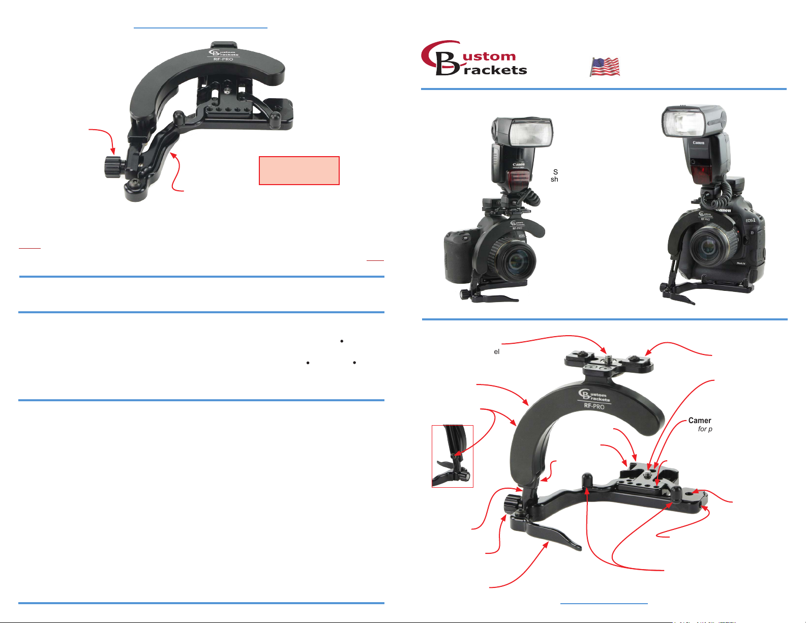
Shown with
short camera
Shown with
tall camera
™
™
Captive ash screw
“D” clip stainless steel
1/4” x 20 thread
Flash rotator
Flash anti-twist (2)
Camera screw
“D” style stainless steel
1/4” x 20 thread
Upright screw
on backside
Camera plate
Camera position holes (2)
for positioning camera
front to back
Strap slot
Camera plate position holes (5)
for positioning camera
left to right
Tripod hole
1/4” x 20 thread
Backside of
bracket shown
Flash rotator
base
Upright
Connector Mounting Hole
Captive upright
lock knob
Fold-out leg
Must be completely folded
in or out to rotate ash
Parts of the RF-PRO
For accessories RF-C1, RF-C2, RF-C3
Camera Anti-Twist (2)
Adjustable front to back
Page 2
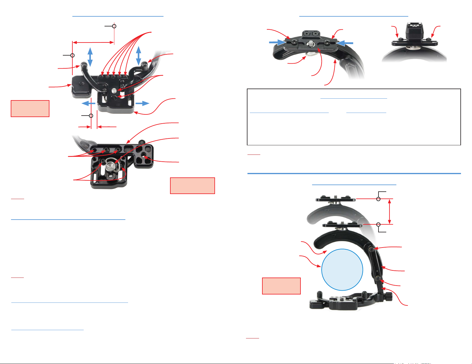
Attaching the camera to the bracket
Attaching the ash cord to the ash mount
Center of Lens
Camera plate position holes (5)
1-11/16”
End of support
for positioning camera
left to right
Camera anti-twist
Adjustable front to back
Camera anti-twist
Adjustable front to back
Support
Camera position holes (2)
for positioning camera
front to back
Camera plate
Top view of
camera plate
Support position holes (3)
for positioning camera
left to right
Camera anti-twist screws (2)
Left position
5/16”
Support
Camera screw
“D” clip stainless steel
1/4” x 20 thread
Tripod hole
1/4” x 20 thread
Bottom view of
camera plate
Note:
- Prior to attaching the camera, raise the ash rotator to the up position (see: back view of bracket).
- The camera plate has been factory set for small cameras with the camera mounting hole on center of the lens.
(1) Setting the camera plate position - Left to Right
The camera plate has ve (5) position holes (5/16” apart) for positioning the camera plate left to right.
Two (2) screws are provided to attach the camera plate to the bracket. Once the correct left to right position has
been determined, use any two support position holes which line up with the camera plate position holes to attach
the camera plate using the 1/8” Allen wrench provided with bracket.
For smaller cameras, or those without add-on vertical grips / battery packs, position the camera plate with a
distance of 5/16” from left position.
For taller cameras, or those with add-on vertical grips / battery packs with the camera mounting hole on center
with the lens, position the camera plate to left position.
Note:
Some add-on vertical grips / battery packs have the mounting screw hole off center to the lens. Determine the
correct position to mount the camera plate to the support which locates the center of the lens as close to 1-11/16”
from the end of the support.
(2) Setting the camera plate position - Front to Back
The camera plate has two (2) camera screw holes for locating the camera front to back. Attach the camera using
one of the camera screw holes. Position of the camera is a customer preference on how comfortable it feels
when holding the bracket in the horizontal and vertical positions.
(3) Setting the camera anti-twist
Once the camera is positioned properly, adjust the two (2) camera anti-twists to contact the front of the camera.
Tighten the two (2) camera anti-twist screws located on the bottom side of the camera plate using the 1/8” Allen
wrench provided with bracket..
An additional hole in the anti-twist is provided if the camera screw “D” clip interferes with the anti-twist screws.
Anti-twist
Captive ash screw
“D” clip
Flash mounting plate
Anti-twist
Anti-twist
Shown with Canon
Off Camera cord II attached
Anti-twist
Flash rotator
Flash anti-twist procedure
Canon off-camera cord II, Canon Cord 3,
Nikon SC-17 cords (rst time installation)
1-
Attach cord with ash screw
2-
Slide one anti-twist to cord
Slide other anti-twist to cord
34-
Tighten ash screw to cord
(do not tighten completely)
(tighten anti-twist screw)
(tighten anti-twist screw)
Nikon SC-28, SC-29 Cords
(rst time installation)
1-
Attach cord (reversed) with ash screw
2-
Slide left anti-twist to cord
Remove cord and install normal
34-
Slide right anti-twist to cord
Tighten ash screw to cord
5-
(tighten anti-twist screw)
(tighten anti-twist screw)
(do not tighten completely)
Note:
Do not rotate the ash rotator unless a ash cord or the
to the ash mounting plate and “D” clip of the screw is folded down. Rotating without one of these attached
may cause damage to the rotator and void warranty.
RF-FT
(mount for wireless ash operation) is attached
Adjusting the ash rotator height
Up position
Height Adjustment
Down position
Equal space around lens
Upright screw
Lens outside diameter
Up position
(shown for reference)
Position rotator
for equal space
around lens
Back view of
bracket
Flash rotator base
Upright screw
Down position
Upright
The ash rotator is adjustable to work with short or tall cameras.
Adjust by loosening the upright screw, then position the rotator to be centered around the lens of the camera.
After desired position of rotator is set, lock upright screw using the 1/8” Allen wrench provided with bracket.
Note:
- Rotating without equal space around lens may cause damage to the lens or bracket.
- The leg must be completely folded in or out to rotate ash to avoid damage to the bracket.
 Loading...