

Page 1
BRACKET INSTRUCTIONS
Digital PRO-M, Digital PRO-E, Digital PRO, Digital PRO-SV
Innovative Camera Supports
QRS-H2, QRS-E2, QRS-2
Made in USA
U.S. Patent 6,354,544
Cleveland, Ohio 44143
Toll Free 800-530-2289
website: www.custombrackets.com
email: info@custombrackets.com
32 Alpha Park
phone 440-446-0819
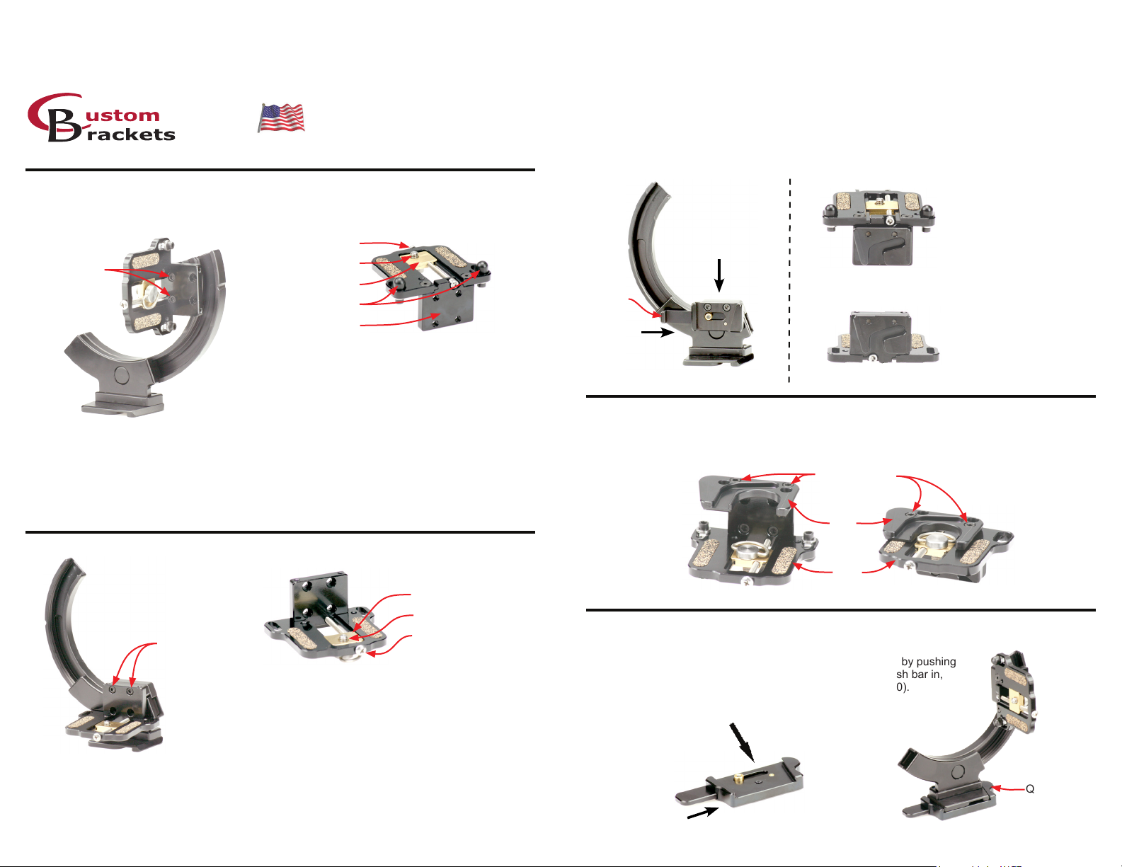
Attaching the camera quick release (QR-C kit, QR-C, C-SP)
Attach the camera quick release (QR-C) to the bracket using the two screws (8-32 thread x 1/2” long
socket head screw) and Allen wrench (9/64”) supplied with your bracket (gure #5)
Attach the camera subplate (C-SP) to the camera mounting plate (CMP) using the two screws
(8-32 thread x 5/16” long socket head screw) supplied with the C-SP and Allen wrench (9/64”)
supplied with your bracket per either gure #6 or #7.
Attach your camera per the CMP instructions.
While pushing in the push bar on the QR-C (step 1 in gure #5), slide the C-SP (attached to the CMP)
downwards into the QR-C (attached to the bracket) (step 2 in gure #5). The push bar on the QR-C
needs to be pushed in when attaching and detaching the C-SP.
Attaching your camera to the CMP
Camera without add on vertical grips or battery packs
Adjusting Screw
Two screws for
mounting CMP
Figure #1
Turn the adjusting screw counterclockwise using a Phillips screwdriver to move the camera
3 -
screw plate forward until the camera touches one of the anti-twist posts. Then turn an additional
1/4 turn (make sure camera is facing straight forward).
Tighten the “D” style camera screw completely.
4 -
Loosen second anti-twist post (if it is not touching the camera) using the same Allen wrench
5 -
(9/64”) and move it until it touches the camera and then tighten.
“D” style camera screw
Camera screw plate
(2) Anti-twist posts
Vertical plate
1 -
Attach the camera plate (CMP) to the bracket using the two screws (8-32 thread x 1/2” long socket
head) and Allen wrench (9/64”) supplied with your
bracket (gure #1).
Attach your camera with lens toward the
2 -
anti-twist posts. Once the “D” style camera
screw is tightened, loosen 1/2 turn (gure #2).
Camera with add on vertical grips or battery packs
Figure #3
Two screws for
mounting CMP
3 -
Remove the “D” style camera screw and install from opposite side as shown.
Attach your camera with lens toward vertical plate. Once the “D” style camera screw is tightened,
4 -
loosen 1/2 turn.
Turn the adjusting screw counterclockwise with a Phillips screwdriver to move the camera screw
5 -
plate forward until the camera touches the vertical plate. Then turn an additional 1/4 turn.
6 -
Tighten the “D” style camera screw completely.
Figure #4
1 -
2 -
Attach the camera plate (CMP) to the bracket using the two screws (8-32 thread x 1/2” long socket
head) and Allen wrench (9/64”) supplied with your
bracket (gure #3).
Remove the anti-twist posts using the Allen
wrench (9/64”) provided with the bracket. Refer
to picture at the top of this page (gure #4).
Camera screw plate
“D” style camera screw
Adjusting Screw
Figure #2
C-SP attached to CMP
for short cameras and
cameras without vertical
grips / battery packs
C-SP attached to CMP
for tall cameras and
cameras with vertical
grips / battery packs
Push bar
1 - Push the
push bar in
2 - Slide C-SP in
from above
Figure #5
Figure #6
Figure #7
Attaching the camera bottom plate (CBP)
Attach the camera bottom plate (CBP) to the CMP using the two screws (8-32 thread x 1/2” long
socket head screw) supplied with your CBP and Allen wrench (9/64”) supplied with your bracket.
CBP attached
to CMP for short
cameras and
cameras without
vertical grips /
battery packs
Figures #8 and #9 are showing the CMP up-side-down with the CBP attached
Two screws for
Figure #8
mounting CBP
CBP
CMP
Figure #9
CBP attached
to CMP for tall
cameras with
vertical grips /
cameras and
battery packs
Attaching the bracket to the tripod quick release (QR)
Attach the tripod quick release (QR) to any tripod by screwing the QR
onto the 1/4-20 bolt on the tripod. Attach the bracket to the QR by pushing
in the push bar (step 1 in gure #10), and while holding the push bar in,
slide the bracket into the QR from the front (step 2 in gure #10).
Figure #11 shows the bracket in the quick release.
2 - Slide bracket in
from front side
Push Bar
QR
1 - Push the
push bar in
Figure #10
Figure #11
Page 2
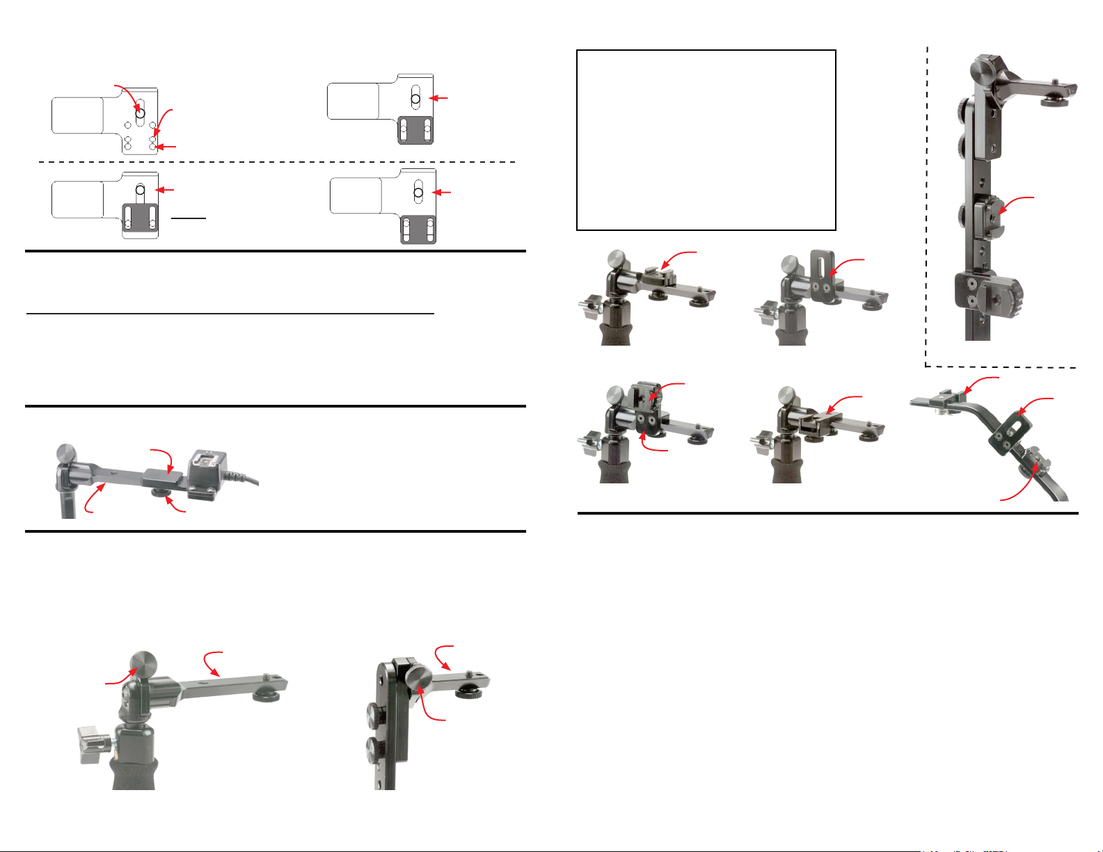
Attaching your ash cord to the FCN
Use the examples below to set your FCN. Screw cord onto plate and adjust the plastic piece so that
it is next to the cord.
Flash Screw
FCN
Nikon SC-28 &
Canon Cords
Nikon SC-29
Flash Cord Here
Canon
Off-Camera Cord 2
Off-Camera Cord OC-E3
Flash Cord Here
Nikon SC-17
Nikon SC-28
Flash Cord Here
Nikon SC-29
Attaching your ash cord to the Digital PRO-E
Use the steps below to set your anti-twist plates (rst time installation only).
Canon off-camera cord II, Canon Cord 3, Nikon SC-17, Nikon SC-28, SC-29 Cords
Attach cord with screw, do not tighten completely (Nikon cords will be set in nal position in step 3).
1-
**Canon cords come out front, Nikon cords come out left side (towards upright).
2-
Slide right anti-twist plate (away from upright side) to cord and tighten anti-twist screw.
Remove cord (Canon users skip this step) and repeat step 1 with cord coming out right side.
34-
Slide left anti-twist (upright side) to cord and tighten anti-twist screw.
5-
Tighten ash screw to cord.
Attaching the ash plate (FCN) to the bracket
Flash plate
Flash receiver
Flash receiver knob
Loosen the ash receiver knob. Slide the ash
plate onto the ash receiver until it stops. Then
retighten the ash receiver knob.
(Shown with Nikon SC-17 cord)
Using the ash lock on the
Digital PRO-M, Digital PRO, QRS-H2, QRS-E2, QRS-2
The ash lock knob will lock the ash in any tilt position desired.
1 - Loosen the ash lock knob, tilt the ash to the desired position. Then retighten the ash lock knob.
Flash receiver
Flash lock knob
Digital PRO-M &
Digital PRO Bottom Upright
Flash receiver
Flash lock knob
QRS-H2, QRS-E2
& QRS-2 Upright
**QRS-2 not shown
Attaching accessories (AP, MC, FT-JR)
Digital PRO-M (gure #15, #17)
MC
Digital PRO-E (gure #19)
QRS-H2 and QRS-E2 (gure #14)
QRS-2 (gure #14) (Shown from back)
Digital PRO-M (gure #16, #17)
AP
Digital PRO-E (gure #19)
QRS-H2 and QRS-E2 (gure #14)
QRS-2 (gure #14) (Shown from back)
Digital PRO-M (gure #18)
FT-JR
Digital PRO-E (gure #19)
MC
Figure #15
MC
AP
Figure #17
AP
Figure #16
FT-JR
Figure #18
Figure #14
Figure #19
MC
Warranty
For a period of one year from date of purchase, Custom Brackets will repair or replace free of charge,
any defect in material or workmanship. Warranty does not cover repairs due to customer abuse,
negligence, impact or any modications made by the customer. Warranty service is available by
returning the Bracket (prepaid) to Custom Brackets. All returns must include a return authorization
(RA) number (contact Custom Brackets to obtain), letter explaining the problem, and a copy of the
sales receipt.
Repair
Repair service is available by returning the Bracket (prepaid) to Custom Brackets. All returns must
include a return authorization (RA) number (contact Custom Brackets to obtain) and letter explaining
the problem. A repair cost will be issued and must be approved prior to any repairs.
Maintenance
The Bracket was designed to be completely maintenance free. The rotation tension is factory set.
Adjusting the tension will void the warranty and may damage the bracket.
Important information for Digital PRO-M and Digital PRO
The adjustable upright has a safety stop installed to prevent the ash mounting plate from hitting the
top of the camera. If the upright lock knob is backed out, it will clear the safety stop and allow the
upright to be retracted completely into the grip for storage.
Important information for Digital PRO-M, QRS-H2, QRS-E2 and QRS-2
The ash tilt has a lock knob for locking the angle of ash. When the lock knob is released, tilt the
ash to a different position. The tension of the tilt is factory set, adjusting it may cause damage to
the camera, ash, and / or bracket.
MC
MC attached
to AP
FT-JR
AP
 Loading...