

Page 1

LIMITED WARRANTY
If your product does not work properly because of a defect in material or workmanship, Custom Autosound Mfg.,Inc. (the Company) will for the length of the
period indicated on the chart below, which starts with the date of original purchase (“Limited Warranty period”), at its option either (a) repair your product with
new or refurbished parts, or (b) replace it with a new or refurbished product. The
decision to repair or replace will be made by the company.
During the “Labor” Limited Warranty period there will be no charge for labor.
During the “Parts” Limited Warranty period, there will be no charge for parts. This
Limited Warranty is extended only to the original purchaser and only covers
product purchased as new. A purchase receipt or other proof of the original purchase date is required for Limited Warranty service.
To obtain repairs or replacement within the terms of this warranty, the product
should be delivered, transportation prepaid, to the Company at the address
shown below.
This warranty does not extend to the elimination of car static or motor noise correction antenna problems, costs incurred for removal or reinstallation of product,
or damage of tapes, speakers accessories or car electrical systems.
This warranty does not apply to any product or part thereof which has been
damaged through alteration, mishandling, misuse neglect, water damage or
accident.
ANY IMPLIED WARRANTY IS LIMITED TO THE DURATION OF THIS WRITTEN WARRANTY. UNDER NO CIRCUMSTANCES SHALL THE COMPANY BE
LIABLE FOR ANY LOSS OR DAMAGE, DIRECT OR CONSEQUENTIAL, ARISING OUT OF THE USE OR INABILITY TO USE THIS PRODUCT: No person or
representative is authorized to assume for the Company any liability other than
expressed herein in connection with the sale of this product.
Some states do not allow limitations on how long an implied warranty last or the
exclusion or limitation of incidental or consequential damage to the above limitations or exclusion may not apply to you.
This warranty gives you specific legal rights and you may also have other rights
which vary from state to state.
1030 W. Williamson Ave. Fullerton CA. 92833
800-888-8637 714-773-1423 FAX 714-773-1523
Product or Part Name PARTS LABOR
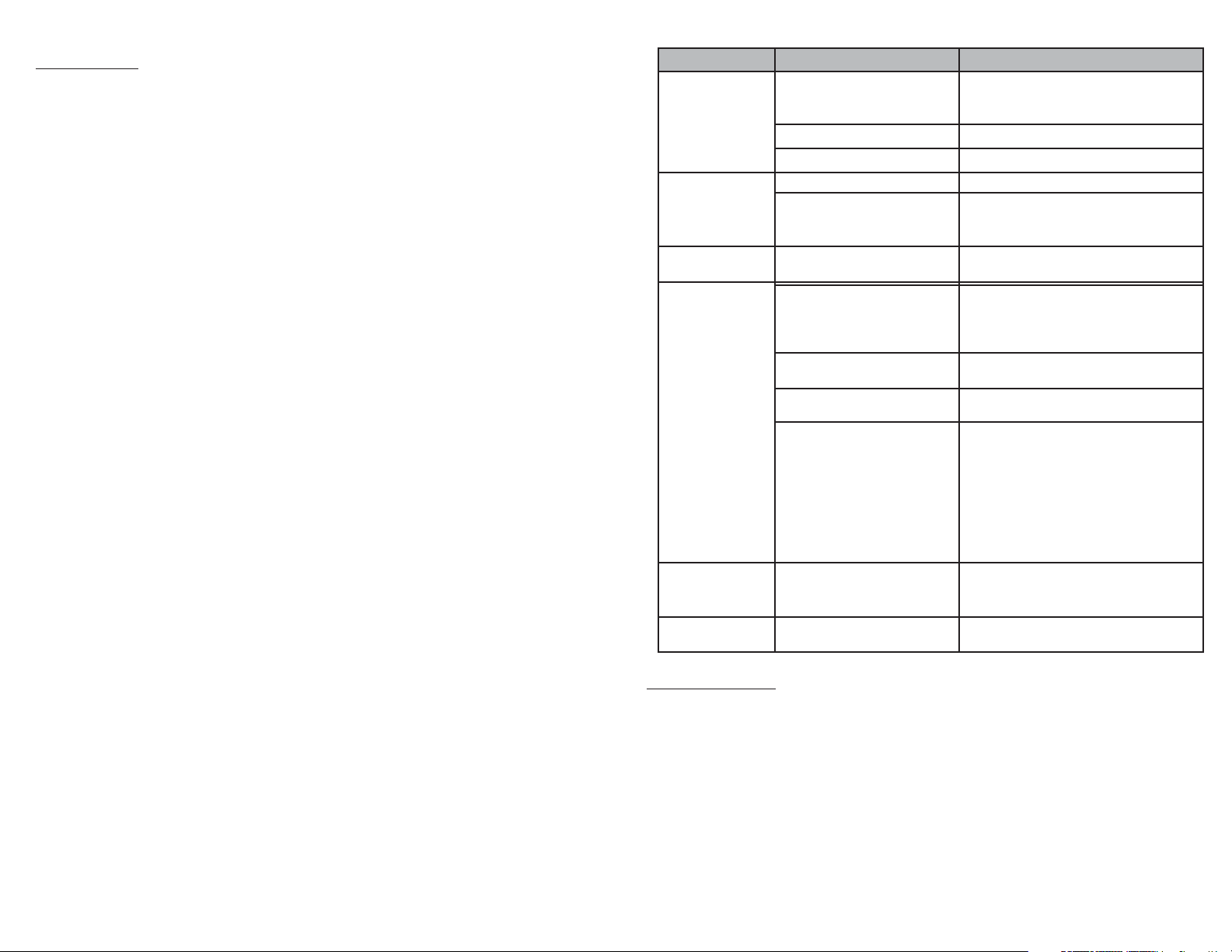
All In-dash car radios, radio/tape
player combinations.
Two (2) Years One (1) Year
• AM/FM Stereo 200 watts 4x50
• 2.4G RF Comander Control (radio frequency, no line of sight required)
• USB MP3/WMA Flash Drive Player
• iPod® Direct Control Interface (built into tuner/amp unit/cable included)
• Alpha Numeric LCD Display for Artist / Song Titles on USB and iPod®
• CD Control (optional 6 disc CD changer or CD1 single cd/dvd)
• Auxiliary Audio Input
• 4 Channel 3 Volt RCA Pre-Outs (for optional Amplifiers)
• Subwoofer Pre-Out (for optional Subwoofer Amp)
• Electronic Volume, Bass, Treble, Balance, Fader
• 5 Selectable iEQ curves – pop/jazz/classic/beat/rock
• 0 Memory Current Draw (will not drain car battery when unit not in use)
• 30 Station pre-sets (18FM / 12AM)
• Power Antenna 12V trigger lead
• Blue LED Illumination on buttons and display
• Adjustable Contrast for LED Display
• Adjustable USA/LATIN/EUROPE Frequency spacing
Page 2
1
14
CONTENTS
Introduction.............................................................................2
Safety Information .................................................................1
Installation......................................................................7,8,11
Basic Operation ................................................................. 3-4
Tuner Operation..................................................................... 5
USB Operation.....................................................................9
iPod Operation .................................................................... 11
Pairing the Wireless Remote Control...........................................10
CD Operation
(Requires USA-CD60 OR USA-CD1CD/DVD PLAYER)........................5
Troubleshooting....................................................................14
Specifications ...............................................................................13
Protect from Water
Do not submerge or expose the product to water, as this can cause electrical shorts, fire
or other damage.
Protect from High Temperatures
Exposure to direct sunlight for an extended period of time can produce very high temperatures inside your vehicle. Give the interior a chance to cool down before starting playback.
Do not mount radio within close proximity of engine compartment.
Use the Proper Power Supply
This product is designed to operate with a 12 volt DC negative ground battery system.
WARNING:
• DO NOT OPEN, DISASSEMBLE OR ALTER THE UNIT IN ANY WAY. Doing so may
result in fire, electric shock or product damage.
• USE THE CORRECT AMPERE RATING WHEN REPLACING FUSE. Failure to do so
may result in fire, electric shock or product damage.
• DO NOT INSTALL IN LOCATIONS THAT MIGHT HINDER VEHICLE OPERATION.
Doing so may obstruct vision or hamper movement which can result in a serious accident.
• INSTALL THE WIRING SO THAT IT IS NOT CRIMPED OR PINCHED BY SCREWS OR
SHARP METAL EDGES. Route the cables away from moving parts or sharp pointed
edges. This will prevent crimping and damage to the wiring. If the wiring must pass
through a metal hole, be sure to use a rubber grommet to prevent the wire's insulation
from being cut by the metal edge of the hole. It is also recommended to apply sealing
caulk to any opening that may potentially allow water to enter.
• Be sure to choose a location that is flat and has clearance above the unit to prevent any
damage, as well as allow for ventilation.
• Before drilling any holes, carefully inspect the area underneath and behind the mounting
surface where the devices will be mounted to make sure it will not interfere with existing
wires, fuel lines, the fuel tank or any other objects that could be damaged.
• Always disconnect the vehicle negative battery terminal to prevent accidental shorting
during installation.
SAFETY INFORMATION
Problem Cause Measure
No Power
The vehicles accessory
switch is not on
If the power wire (red) is properly connected to the vehicles accessory terminal, switch the ignition key to “ACC”
The fuse is blown Replace the fuse
Unit not grounded Check ground connection
No Sound
Volume set too low Increase the volume to audible level
Wiring is not properly con-
nected. Or Mute is on.
Correct wiring connections. (speaker
wires can not be grounded or touch
each other). Turn off Mute
Operation Keys
do not work
The internal processor is not
operating properly
Press the reset button with a ball point
pen. (See page 7)
No Sound or Error
Code on USB
Music files protected Make sure none of the audio files are
DRM or protected, use only .mp3 files
or unprotected Windows Media format
files
To many songs on USB Do not have more than 999 songs on
the USB drive
File names to long Shorten file names to 64 character
total or less
USB player requires driver
software
This radio will recognize most USB
devices that do not require any form of
special driver software. Many of the
new Sony walkman MP3 players are
not compatible due to the need for
special software to communicate with
these devices. Conventional USB
memory sticks work great.
iPod not as loud
as other sources
iPod sound check in on Go to the Settings menu on your iPod
and turn off the Sound Check function.
This will restore the output level.
Tuner channel
spacing wrong
Tuner not set to proper
region
TROUBLE SHOOTING
See page 4 system menu item (4)
iPod compatibilty
This unit is equipped with an iPod ready function that will allow you to control
your iPod (if compatible) using the control panel control buttons. The following
iPod versions are supported:
• iPod 3G (firmware version 2.2 only)
• iPod Mini
• iPod 4G
• iPod Photo
• iPod Nano (1st, througn 5th generation)
• iPod 5G (Video)
• iPod Touch
• iPod Classic
Page 3

SPECIFICATIONS
FM Radio
Frequency Coverage (USA) . . . . . . . . . . . . . . . . . . . . . . . . . . . . . . . . . . . 87.5 to 107.9 MHz
Frequency Coverage (Europe) . . . . . . . . . . . . . . . . . . . . . . . . . . . . . . . . . . 87.5 to 108 MHz
Sensitivity (S/N=30dB) . . . . . . . . . . . . . . . . . . . . . . . . . . . . . . . . . . . . . . . . . . . . . . . . . . 4µV
Image Rejection . . . . . . . . . . . . . . . . . . . . . . . . . . . . . . . . . . . . . . . . . . . . . . . . . . . . . >45 dB
Stereo Separation . . . . . . . . . . . . . . . . . . . . . . . . . . . . . . . . . . . . . . . . . . . . . . . . . . . . >25 dB
AM/MW
Frequency Range (USA). . . . . . . . . . . . . . . . . . . . . . . . . . . . . . . . . . . . . . . . . 530-1710 kHz
Frequency Range (Europe). . . . . . . . . . . . . . . . . . . . . . . . . . . . . . . . . . . . . . . 522-1620 kHz
Sensitivity (S/N=20dB) . . . . . . . . . . . . . . . . . . . . . . . . . . . . . . . . . . . . . . . . . . . . . . . . 36 dB
General
Operating Voltage . . . . . . . . . . . . . . . . . . . . . . . . . . . . . . . . . . . . . . . . . . . . . . . . DC 12 Volts
Grounding System . . . . . . . . . . . . . . . . . . . . . . . . . . . . . . . . . . . . . . . . . . . Negative Ground
Speaker Impedance . . . . . . . . . . . . . . . . . . . . . . . . . . . . . . . . . . . . . . 4-8 ohms per channel
Tone Controls:
Bass (at 100 Hz) . . . . . . . . . . . . . . . . . . . . . . . . . . . . . . . . . . . . . . . . . . . . . . . . . : ±10 dB
Treble (at 10 kHz). . . . . . . . . . . . . . . . . . . . . . . . . . . . . . . . . . . . . . . . . . . . . . . . . : ±10 dB
Power Outpu t . . . . . . . . . . . . . . . . . . . . . . . . . . . . . . . . . . . . . . . . . . . . . . . . . . . . . . 50W x 4
Current Drain. . . . . . . . . . . . . . . . . . . . . . . . . . . . . . . . . . . . . . . . . . . . . . . .15 Ampere (max.)
Commander Dimensions. . . . . . . . . . . . . . . . . . . . . . . . . . . . . .5.15” (W) x 1.2” (D) x 3.7” (H)
Tuner/Amp Dimensions. . . . . . . . . . . . . . . . . . . . . . . . . . . . . .8.35” (W) x 6.55” (D) x 2.4” (H)
Introduction
Thank you for your purchase of a Custom Autosound radio.
This factory made AM/FM receiver is specifically designed and manufactured for your
classic special interest vehicle. It is a reflection of over 30 years of customer feedback
regarding preferred features, vehicle compatibility, cosmetics and quality components.
The quality of the components and various parts that are used in our radios were developed in a California audio research laboratory. The laboratory researched and assembled the finest affordable iPod/USB/CDC controller radio tuner and amplifier sections.
Custom Autosound and its staff own over 16 classic special interest cars and trucks.
These vehicles are used for research and development, car shows meets and much
personal pleasure. We find that our custom radios only sound as good as the speakers
they are matched with and a quality installation.
We also manufacture a full line of rear and dual front and dual voice coil speaker
assemblies to fit in the original speaker areas, rear and overhead speaker assemblies
and custom radios for over 300 different year groups and makes of classic vehicles plus
Secretaudio the hideaway AM/FM CD Controller radio for any vehicle.
Your Custom Autosound authorized dealer has information regarding our speakers and
special speaker assemblies, as well as information regarding custom radios for cars
other than yours.
Again, we thank you for your purchase! You have increased the value and "Driving
Pleasure" of your classic without damaging the originality.
Regards, Carl Sprague
President
Custom Autosound
It’s advised that you do not return defective units to your dealer. There is generally no
"exchange" e.g.(as is Standard Electronics Industry Policy). Also, most dealers do not
have radio technicians, test benches, etc and a return to factory through a dealer can
extend turn-around times by weeks!
Please call Custom Autosound, requesting technical assistance if a problem occurs. We
will gladly trouble shoot/advise step by step.
If your unit is in need of repair, Please ship to us, UPS preferably. We will repair or
replace and return ASAP! Normal turn around time is 7 business days plus shipping
time.
Custom Autosound Mfg, Inc. 800-888-8637
1030 West Williamson Ave Fax 714-773-1523
Fullerton, CA 92833 www.custom-autosound.com
13
2
Page 4
3
12
Power On/Off
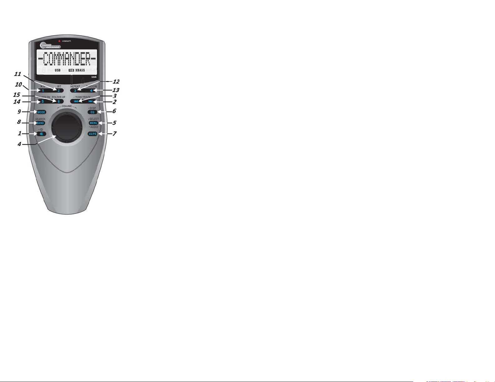
Press the POWER button (1) to turn
the unit on. The unit will resume the last
mode (Tuner, Aux, etc.).
Volume Control
To increase the volume, turn the VOLUME knob (4) clockwise. To decrease
the volume, turn the VOLUME knob (4)
counter clockwise.
Mute
Short press of the power button (1) will
MUTE the sound. A second short press
of the power button will resume audio
output.
Mode
Press the MODE button (9) on the control panel to select a different mode of
operation, as indicated on the display
panel. Available modes include Tuner,
USB, iPod, CD and AUX In.
NOTE: iPod will be
module is not installed.
Audio Menu
Press the MENU button (5) on the control panel to access the audio menu. You can navigate through the audio menu items by pressing the MENU button repeatedly. Once the
desired menu item appears on the display, adjust that option by turning the VOLUME +/control (4) within 5 seconds. The unit will automatically exit the audio menu after five seconds of inactivity.
The following menu items can be adjusted.
Bass Level Use the VOLUME knob to adjust the Bass level range from “-6” to “+6”.
Treble Level Use the VOLUME knob to adjust the Treble level range from “-6” to “+6”.
Balance Use the VOLUME knob to adjust the Balance between the left and right speak-
ers from “L12” (full left) to “R12” (full right).
Fader Use the VOLUME knob to adjust the Fader between the rear and front speakers
from “R12” (full rear) to “F12” (full front).
Category Navigate Search
1. Short press the “button” (8) until “Category” appears on the LCD
2. Press Select (5) or rotate the Volume knob (4) to enter into Category Search.
Rotate the VOL knob clockwise for Category up, Rotate the VOL knob counter
clockwise for Category down.
3. Once the desired Category is displayed, press Select (5).
4. Rotate the VOL knob clockwise for CH up and counter clockwise for CH down. Or
press Tune Up/Dn to choose channel.
(Note: At this moment, press AS/PS (7) to go back to last level of Category selection)
5. Once the desired CH is displayed, press Select button (5) to confirm.
Channel Up/Down Tuning
Press the TUNE/TRK |<< / >>| buttons (2/3) to search for a channel. Press and hold the
TUNE/TRK buttons to fast search.
Storing Preset Channels
The preset buttons (10-15) can be used to store 6 channels, allowing convenient access
to your favorite channels. 1. Select the channel you want to store in memory.
2. Press and hold a preset button (10-15) until the corresponding preset button #
appears. 3. Repeat steps 1 and 2 to program additional channels.
Quick Tuning
Press one of the six preset buttons (10-15) to select a preset channel directly.
Channel Direct Access Searching (8)
- Press BAND button (8) to access direct tune mode, "Direct -T" appears on the display
for a few seconds.
- Rotate the Knob (4) Clockwise or Short Press Select button (5) to confirm entry into
the Direct Tune mode
- Rotate knob clockwise or counter-clockwise to navigate through number 0-9
- Default interface display is SR CH 0__
- The 1st digit only allows numeric entry from 0, 1 & 2 for Channel Number
- The 2nd & 3rd digits allow numeric entry from 0, 1 to 9 for Channel Number
- Short press Select button (5) to confirm the entry of the current digit, use Track up /
down button (2) or (3) as cursor to move back & forth among the 3 digits
continued on page 13
skipped if the
Page 5
Tuner/Amplifier Mounting
1. Choose a mounting area for the tuner/amp module that will provide plenty of ventilation to prevent the amplifier from overheating. The tuner/amp module can be mounted
in the horizontal or vertical position. Please note that when mounting in vertical position, do not mount with the harness exit points facing straight up, as this will reduce the
efficiency of the heat sink cooling.
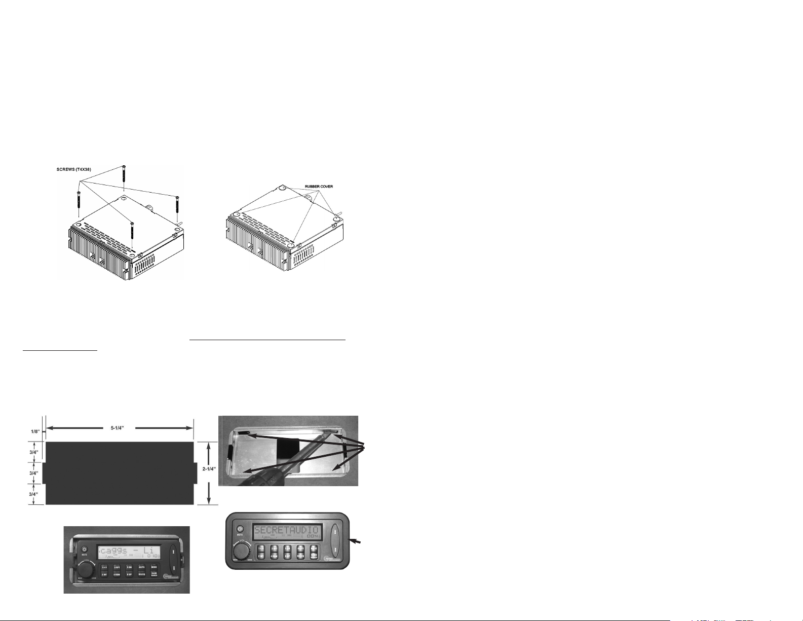
2. Using the shortest length of the recommended size screws possible, mount the
tuner/amplifier as detailed in the diagram below.
3. Route the tuner/ amplifier harness and cable throughout the vehicle as required.
Keep some slack in the harness / cables so it won't be too tight, as this can cause
damage to the wires.
4. Follow the wiring diagram carefully and make certain all connections are secure and
insulated with crimp connectors or electrical tape to ensure proper operation.
Optional Wired Commander flush Mount
(1) Find a flat area that is a minimum of 5-3/4” w x 2-3/4” h
(2) Check area behind for any obstructions. Needs a min. of 1” clearance
(3) Cut a 5-1/4” w x 2-1/4 h hole for the flush mount bezel. Cut 1/8”w x 3/4” high
clearance for tabs on side of LCD. (fig.1) Be extremely careful to not cut this
opening oversize or the trim bezel will not cover up the hole. Best to cut the opening
slightly small and then file to fit.
(4) Insert metal bezel into cutout and bend mounting tabs (A) outward to secure it into
the opening. fig. (2)
(5) Place commander into bezel (fig. 3) and press fit plastic trim ring (B) over the
commander. (fig.4)
A
System Menu
1. Press and HOLD the MENU button (5) for more than 3 seconds to enter the
system menu.
“MENU” will appear on the display, followed by the first menu item, “CON
TRAST.”
2. Press the TUNE/TRK >>| or |<< button (2, 3) or press the MENU button repeatedly
to navigate the system menu and select the desired item.
3. Turn the VOLUME +/- knob (4) to adjust the selected menu item.
4. Press the AS/PS button (7) to return to the previous operation immediately or wait
for 5 seconds to return automatically. The following items can be adjusted:
• CONTRAST (0 – 10): Set LCD contrast.
• AREA (USA/LATIN/EUROPE): Set frequency spacing for various regions.
• VOL PGM (0 – 46): Select an automatic turn-on volume.
• BEEP TONE (ON/OFF): Turn the audible beep ON/OFF (heard when function /but
tons are selected).
• RESUME: Return the EEPROM to factory default set up values.
"Yes" will blink on the LCD to confirm. Press SELECT(4) to select.
Equalizer
Press the EQ button (6) to turn on the equalization function and select between five
predefined bass and treble curves: OFF > POP > JAZZ > CLASSIC > BEAT > ROCK.
Auxiliary Input
To access an auxiliary device:
1. Connect a portable audio player to the AUX IN cables on the back of the tuner box.
2. Press the MODE button (9) to select Aux In mode.
3. Press MODE again to cancel Aux In mode and go to the next mode.
Liquid Crystal Display (LCD)
The current frequency and activated functions are shown on the LCD panel.
NOTE: LCD panels may take longer to respond when subjected to cold temperatures
for an extended period of time. In addition, the visibility of the numbers on the LCD
may decrease slightly. The LCD display will return to normal when the temperature
increases to a normal range. The contrast of the display is adjustable - see system
menu
Quick Exit Hot Key
In the following modes and conditions, press the AS/PS button (7) 3 seconds to quickly
exit the current operation without waiting for the system default time out:
• System menu operation • Searching mode • Audio menu operation
11
fig. (2)
fig. (1)
B
fig. (3)
fig. (4)
4
Page 6

5
10
TUNER OPERATION
Select a Band
Press the BAND button (8) to change between three FM bands and two AM (MW) bands.
Manual Tuning
Press the TUNE/TRK >>| or |<< buttons (2, 3) to seek stations up/down step by step.
Auto Seek Tuning
Press and hold the TUNE/TRK >>| or |<< buttons (2, 3) to automatically seek the next or
previous strong station.
Preset Stations
Six numbered preset buttons store and recall stations for each band.
Store a Station
Select a band (if needed), then select a station. Press and hold a preset button (10-15) for
two seconds. The preset number will appear in the display.
Recall a Station
Select a band (if needed). Press a preset button (10-15) to select the corresponding
stored station.
Automatically Store / Preset Scan (AS/PS)
Automatically Store
Select a band (if needed). Press and hold the AS/PS (7) button for more than three seconds to automatically select six strong stations and store them in the current band. The
new stations replace any stations already stored in that band.
Preset Scan
Select a band (if needed). Press AS/PS (7) to scan stations stored in the current band.
The unit will pause for ten seconds at each preset station. Press AS/PS again to stop
scanning when the desired station is reached.
CD Changer Mode (For Optional CD Changer/Player)
Selecting a Disc DN(14) UP(15)
To slect a disc, press DN(14) or UP(15) until the desired disc number is showing on the LCD display
Selecting Tracks >>(2) <<(3)
-Press the button >>(2) or <<(3) to skip to next track or last track on the CD.
-Press and hold the button >>(2) or <<(3) to fast forward or fast reverse through
the disc. CD play starts when the button is released.
Play/Pause Disc playback 1 >/II(10)
Press button 1 >/II(10) to pause disc play, press this button again to resume
disc play.
Previewing Tracks (11)
Press the 2 INT button (11) to play only first 10 seconds of each track in the
current disc repeately. Press this button again to stop intro scan and resume
normal play at the current track.
Repeat Play (12)
Press the 3 RPT button (12) during disc play to repeat play the current track,
press this button again to stop repeat play.
Long press this button (12) to repeat play all the tracks on current CD.
Random Play (13)
Press 4/RDM button (13) during disc play to play all tracks on a CD in random
order. Press this button again to stop random play. Long press this button (13)
to random all the tracks on the CD changer.
• During USB mode playback, if the user removes the USB device from main
unit, the unit will automatically switch to FM mode.
Controlling Playback
This unit can play MP3/WMA files stored on a USB Memory device.
File/Folder Intro Play
• Press and hold the 2 INT button (11) for more than 3 seconds while playing
MP3/WMA files to "intro play" all files in the current folder.
• Press the 2 INT button (11) to "intro play" all files.
• Press the 2 INT button again to disable file or folder "intro play".
File/Folder Repeat Play
• Press and hold the 3 RPT button (12) for more than 3 seconds while playing
MP3/WMA files to "repeat play" all files of the current folder.
• Press the 3 RPT button (12) to "repeat play" the current file.
• Press the 3 RPT button again to disable file or folder “repeat play".
File/Folder Random Play
• Press and hold the 4 RDM button (13) for more than 3 seconds while playing
MP3/WMA files to "random play" all files of the current folder.
• Press the 4 RDM button (13) to "random play" all files.
• Press the 4 RDM button again to disable file or folder "random play".
Folder/File Down
• In USB mode, press the preset 5 DN button (14) to move one folder down.
• In USB mode, press and hold to move 10 folders down.
Folder/File Up
• In USB mode, press the preset 6 UP button (15) to move one folder up.
• In USB mode, press and hold to move 10 folders up.
Pairing the Wireless Remote Control
Note: When connecting the SRMS devices for the first time with 2.4 black box
receiver, a mutual registration is required, this is called “Pairing”. This registration is required only for the first time, as wireless remote commander and
receiver devices will recognize each other automatically the next time.
Note: The wireless remote control included in this package was already paired
with the 2.4 Receiver. There is no need to do the pairing again.
SRMS 2.4G Commander Pairing Method:
If the commander & the main unit lost the pairing for some reason, user can
follow the below procedure to make the pairing. 1) Make sure the battery is
already inserted the SRMS wireless remote, and make sure the RF receiver is
connected with the main unit. 2) Check that the main unit is connected to 12
volts and properly grounded. 3) Press any key on the SRMS wireless commander to “WAKE” up the commander from “Sleep or Stand BY” mode. 4)
Long press the mode button for more than 3 sec, display should show (-CLR
+LEARN) 5) Use the VOL KNOB to select: A)Counter-clockwise direction to
select (-CLR) this is to clear previously paried commander,if any. B)Clockwise
direction to select (+ LEARN) this is to pair with new 2.4G commander, or if
the commander lost the pairing for some reason. 6) Follow the instruction as
displayed, press “PWR” button, “ MODE ” button, “DISP” button & “ BAND ”
button in this sequence. once the “ CLEAR ” or “PAIRING” is completed & successful, display will show “CLEAR OK” or “LEARNING OK” respectively.
Page 7

6
9
iPod OPERATION
This unit is equipped with an iPod ready function that will allow you to control
your iPod (if compatible) using the control panel control buttons. The following
iPod versions are supported:
• iPod 3G (firmware version 2.2 only)
• iPod Mini
• iPod 4G
• iPod Photo
• iPod Nano (1st, througn 5th generation)
• iPod 5G (Video)
• iPod Touch
• iPod Classic
NOTE: iPhone not supported. iPod sold separately.
Accessing iPod Mode
The unit will automatically switch to iPod mode
when an iPod is plugged into the iPod cable.
To return to the iPod menu from any other source,
press the MODE button (9) on the control panel or
remote control until “iPod” appears on the display.
Turning the iPod On/Off
The iPod power turns on automatically when an
iPod is connected to 30-pin iPod cable, as long as
the vehicle ignition is turned on. You can turn the
iPod off by disconnecting it from the cable or by
turning the ignition off. When the ignition is turned
off, the iPod will pause and then enter sleep mode after 2 minutes. While the
iPod is connected, the power cannot be turned on or off from the iPod itself.
NOTE: The iPod will continuously recharge when connected to the unit, as
long as the vehicle ignition is turned on. Please note that the SST will not support charging of the iPod Nano 4th generation (Chromatic) or any iPod models
released after September 2008.
NOTE: iPod Connectivity through the USB is not supported.
Controlling Playback
Pausing Playback
During playback, press the 1/>|| button (10) to pause the iPod player. “Pause”
will appear on the LCD. Press 1/>|| again to resume playback.
Repeat Play
During playback, press the 3/RPT button (12) to repeat the current song.
“Repeat” will appear on the LCD. Press 3/RPT again to stop repeat playback.
Random Play
During playback, press the 4/RDM button (13) to play all songs in the current
category in random order. Random play will begin once the current song has
finished playing. “Shuffle” will appear on the LCD. Press 4/RDM again to stop
random playback.
Continued page 9
Selecting Tracks
During playback, press the TUNE/TRK |<< / >>| button (2/3) to play the previous or next track in the current category. Press the TUNE/TRK |<< button (2)
once to play the song from the start position or press TUNE/TRK |<< twice to
play the previous track. Press and hold the TUNE/TRK |<< / >>| button (2/3) to
fast reverse/forward the song.
NOTE: If you press and hold the TUNE/TRK |<< / >>| button to change the current
song to the previous/next song, you will exit fast reverse/forward mode.
Alternate Display Information
Press Display button (6) to change the display information in the following
order:
ARTIST NAME > SONG TITLE > FOLDER NAME.
Search Mode
Press and hold the BAND/SEARCH button (8) to enter iPod search mode.
Press BAND/SEARCH again to access Playlist, Artist, Album, Genre, Song, or
Composer (consecutively).
When search mode is selected, press the select button (5) to confirm selection. Use the VOLUME +/- knob (4) to navigate through various list selections.
Press Select (5) to make your final selection.
USB OR FLASH MP3/WMA OPERATION
This unit supports the USB host function. It can play MP3 and WMA audio format files stored on USB flash memory and some USB music devices.
NOTE: This unit does not support portable hard discs.
NOTE: Exposure to direct sunlight or high temperatures may cause
deformation or other malfunction of the USB device.
NOTE: Do not remove the USB device during play, as this may result in
loss or damage to data. Always back up and save important data to your
computer
.
Accessing USB Mode
Press the MODE button (9) to access USB mode.
• When a USB device is inserted into the USB connector, the unit will automatically switch to USB HOST mode from current playing mode.
• If there are no music files stored on the USB device, the LCD will display
"No File" for 3 seconds and then switch to the previous mode.
• If the unit cannot play the file, the LCD will display "Read Error" for 3 seconds, and then switch to the previous mode automatically.
• If a USB device is not inserted, USB mode will be skipped when pressing
the MODE button.
Page 8
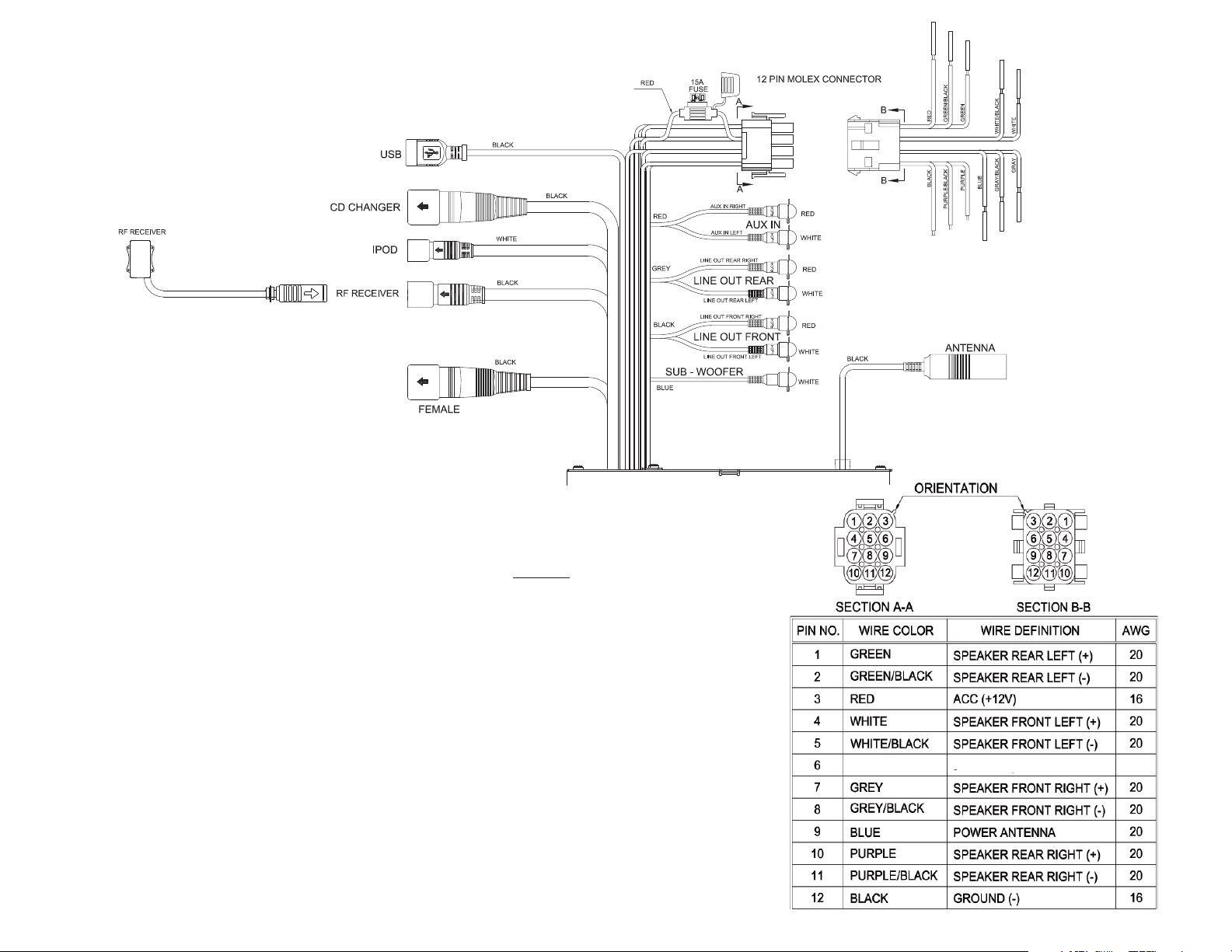
WIRE CONNECTIONS
RESET
7
INSTALLATION
Before you begin, always disconnect the
battery negative terminal.
Important Notes
• Before final installation, test the wiring
connections to make sure the unit is connected properly and the system works.
• Use only the parts included with the unit
to ensure proper installation. The use of
unauthorized parts can cause malfunctions.
• Consult with your nearest dealer if installation requires the drilling of holes or other
modifications to your vehicle.
• Install the unit where it does not interfere
with driving and cannot injure passengers if
there is a sudden or emergency stop.
• Avoid installing the unit where it will be
subject to high temperatures from direct
sunlight, hot air, or from a heater, or where
it would be subject to excessive dust, moisture, dirt or vibration.
• This system requires a minimum of 2 speakers (one speaker for
each right and left channel) If you only have a location for one
speaker our DVC (dual voice coil) speaker can be used. Do not connect any of the speaker leads to each other or
vehicle ground.
• System requires 12 volt negative ground.
• Blue power antenna lead is for 12volt
possitve trigger of optional amplifers or power antenna relay. Do not
connect to any accessory that requires high current. If your
vehicle is not equipped with automatic antenna or amplifiers tape
this lead off.
Reset
The reset switch should be activated for the following reasons:
• initial installation of the unit when all wiring is completed
• function buttons do not operate
• error symbol on the display
Use a ball point pin or thin metal object to press the RESET button,
located on the tuner box. You can recover factory default settings
using the RESUME function located on the system menu. With
“YES” flashing, press the SELECT button (4) to activate.
8
 Loading...