

Cushcraft A4S Instructions
ASSEMBLY AND INSTALLATION
INSTRUCTIONS
A4S
20 / 15 / 10 MeterBeam
C O R P O R A T I O N
951279 (8/98)

A4S
WARNING
THIS ANTENNA IS AN ELECTRICAL CONDUCTOR. CONTACT WITH POWER LINES CAN RESULT IN DEATH, OR SERIOUS
INJURY. DO NOT INSTALL THIS ANTENNA WHERE THERE IS ANY POSSIBILITY OF CONTACT WITH OR HIGH VOLTAGE ARCOVER FROM POWER CABLES OR SERVICE DROPS TO BUILDINGS. THE ANTENNA, SUPPORTING MAST AND/OR TOWER
MUST NOT BE CLOSE TO ANY POWER LINES DURING INSTALLATION, REMOVAL OR IN THE EVENT PART OF THE SYSTEM
SHOULD ACCIDENTALLY FALL. FOLLOW THE GUIDELINES FOR ANTENNA INSTALLATIONS RECOMMENDED BY THE U.S.
CONSUMER PRODUCT SAFETY COMMISSION AND LISTED IN THE ENCLOSED PAMPHLET.
Your Cushcraft A4S Yagi antenna is designed and manufactured to give trouble free service. This antenna will perform as specified if the
instructions and suggestions in this manual are followed and care is used in the assembly and installation. When checking the components
received in your antenna package use the parts listed beside each diagram. There is a master parts list on page 2. If you are unable to locate
any tube or component, check the inside of all tubing. IMPORTANT: Save the weight label from the outside of the carton. Each antenna is
weighed at the factory to verify the parts count. If you claim a missing part, you will be asked for the weight verification label.
Plan your installation carefully. If you use volunteer helpers be sure that they are qualified to assist you. Make certain that everyone involved
understands that you are the boss and that they must follow your instructions. If you have any doubts at all, employ a professional antenna
installation company to install your antenna.
LOCATION
PLANNING
Location of the antenna is very important. Surrounding objects such as trees, power lines, other antennas, etc. will seriously reduce efficiency.
To minimize the effects of surrounding objects, mount the antenna as high and in the clear as possible. If metal guy wires are used, they should
be broken with strain insulators. EXTREME CARE MUST BE USED FOR YOUR SAFETY. YOU MUST INSURE THAT WHILE THE A4S IS
IN OPERATION NEITHER PEOPLE OR PETS CAN COME IN CONTACT WITH ANY PORTION OF YOUR ANTENNA. DEADLY VOLTAGES
AND CURRENTS MAY EXIST. ALSO, SINCE THE EFFECTS OF EXPOSURE TO RF FIELDS ARE NOT FULLY UNDERSTOOD, LONG TERM
EXPOSURE TO INTENSE RF FIELDS IS NOT RECOMMENDED. THERE IS A WARNING STICKER WHICH MUST BE ATTACHED TO THE
BOOM AS SHOWN IN FIGURE I.
MOUNTING
The mast mount bracket will accommodate up to a 2" (5.1 cm) mast. A 1-1/2" OD (3.8 cm) or larger heavy wall tubing mast should be used. A
good heavy duty antenna rotator will provide the best service and longest life. Often it is desirable to mount several antennas on one mast.
To keep possible interaction to a minimum, place your antennas as far apart as you can.
SYSTEM GROUNDING
Direct grounding of the antenna, mast and tower is very important. This serves as protection from lightning strikes and static buildup, and from
high voltage which is present in the radio equipment connected to the antenna. A good electrical connection should be made to one or more
ground rods (or other extensive ground system) directly at the base of the tower or mast, using at least #10AWG ground wire and non-corrosive
hardware. For details and safety standards, consult the National Electrical Code. You should also use a coaxial lightning arrester. Cushcraft
offers several different models, such as LAC-1, LAC-2 and the LAC-4 series.
ASSEMBLY
Assemble your antenna by following the directions and illustrations in steps 1 through 5. After the antenna is completely assembled, verify
dimensions and element spacings for accuracy. Then, return to the section below for final tuning.
Set the element lengths for the portion of the band you want to favor, by using Chart 1 and Figure B. Your A4S is now ready for use. Because
of variations in trap caps, the overall dimensions D-1, 2, 3, 4 may vary as much as 1 inch from the individual dimensions. This will not affect
performance. Always use the individual dimensions when adjusting your antenna.
You may check the VSWR in order to confirm assembly was done properly. The easiest place to check the antenna is likely to be in its final
mounting configuration. Orient the antenna such that it is pointing straight up. The back of the antenna should be at least 2 feet (.6 m) off the
ground.
Run the coax cable from your transmitter to the area in which the antenna is to be tested. The length of this cable or your feedline is not critical.
Connect a good quality VSWR bridge to the end of this cable. Connect a short length of cable [10 ft. (305 cm) or less] from the VSWR bridge
to the antenna under test. Set the transmitter to your center operating frequency and measure the VSWR while taking care not to effect the
measurement with your body. A VSWR of 2:1 or less is satisfactory and will not degrade the performance. If the VSWR is greater than 2:1,
check all dimensions and connectors.
ADD-ON KIT
Adding 30 or 40 meters to your A4S beam is a breeze with the spectacular A744 add on kit. Your'll be on the air quickly operating on your new
band because the A744 easily clamps to your A4S. You can operate on 40 meters or with a simple adjustment 30 meters.
The kit comes complete with reinforced insulator, teflon® proteced high power traps, all hardware and non-stretch lamcord® support line. Cushcraft
makes it easy to add more excitement to your hobby.
TUNING PROCEDURE
A4S
MASTER PARTS LIST
KEY PAR T# QTY
BA Aluminum tubing 2" x 72" x .058 drilled and 1
BB Aluminum tubing 2" x 75-1/4" x .058 swagged and drilled 2
one end
EA Aluminum tubing 1-1/8" x 72" (2.9 x 182.9 cm) drilled 1
EB Aluminum tubing 1-1/8" x 36" (2.9 x 91.4 cm) drilled one 2
EC Aluminum tubing 7/8" x 36" x .058 drilled for U-bolt slotted 1
ED Aluminum tubing 1" x 65" (2.5 x 165.1 cm) slotted 2
EE Aluminum tubing 1" x 46-1/2" (2.5 x 188.1 cm) slotted 2
EF Aluminum tubing 1" x 5-1/4" (2.5 x 13.3 cm) slotted 4
EG Aluminum tubing 1/2" x 35-7/8" ( 1.3 x 91.1 cm) 4
EH Aluminum tubing 3/4" x 48" (1.9 x 121.9 cm) slotted 2
EJ Aluminum tubing 5/8" x 48" (1.6 x 121.9 cm) 2
EK Aluminum tubing 1-1/8" x 24" (2.9 x 61.0 cm) drilled 1
EL Aluminum tubing 1-1/4" x 50" (3.2 x 127 cm) slotted 2
EM Aluminum tubing 1-1/8" x 72" (2.9 x 182.9 cm) slotted 2
EN Aluminum tubing 1" x 24" (2.5 x 61.0 cm) slotted 2
EP Aluminum tubing 1/2" x 48" (1.3 x 121.9 cm) 2
slotted both ends
for U-bolt, slotted both ends.
end, slotted both ends
both ends
one end
one end
both ends
one end
for U-bolt
both ends
one end
one end
KEY PART# QTY
TB 15 meter director trap 2
TC 15 meter driv. & refl. trap 4
TD 10 meter driv. trap 2
TE 10 meter director trap 2
11 010011 #8-32 hex nut 6
27 050027 5/8" Black plastic cap 2
41 011941 #8 Split lock washer 6
53 050053 1/2" Black plastic caps 6
63 170063 2-1/2" Machined aluminum V-blocks 4
95 122095 1" x 10" O.D. Fiberglass insulator drilled for U-bolt 1
99 050099 2" Black plastic caps 2
118 010118 5/16" (.8 cm) hex nut 16
119 010119 5/16" (.8 cm) lock washer 16
123 010123 #8-32 x 1-1/2" (3.8 cm) machine screw 2
130 190130 6" x 6" Aluminum mounting plate 1
156 190156 2" x 1-1/8" Formed aluminum brackets 4
232 010232 8-32 x 2-1/2" (6.4 cm) Round head slotted machine screw 2
326 290326 Danger label 1
404 010404 2 1/8" x 3" (5.4 x 7.6 cm) U-bolt 4
405 010405 2 1/8" x 4" (5.4 x 10.2 cm) U-bolt 4
409 030409 11/16" (1.7 cm) Worm clamp 8
410 030410 1" (2.5 cm) Worm clamp 16
411 030411 1-1/8" (2.9 cm) Worm clamp 8
412 030412 1-1/2" (3.8 cm) Worm clamp 4
414 030414 2-1/4" (5.7 cm) Worm clamp 2
453 100453 Terminal 2
and element screw
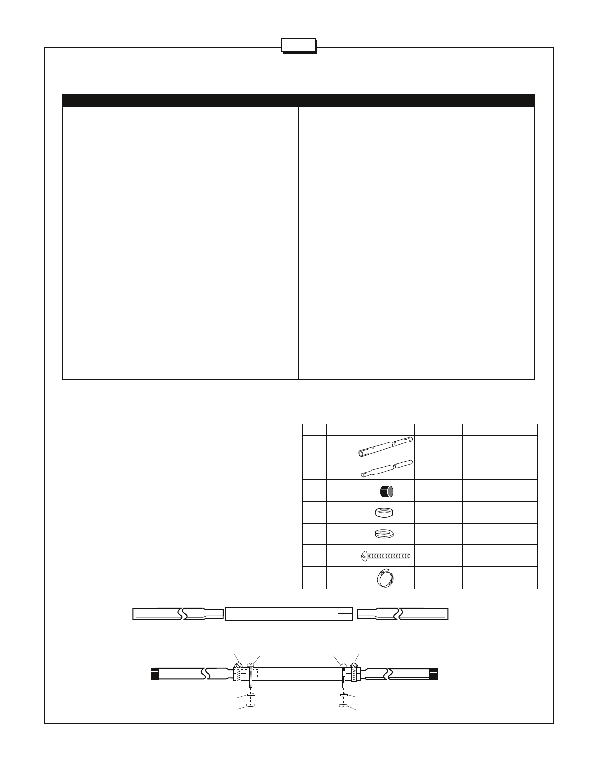
#1 - BOOM ASSEMBLY
Place worm clamps (414) over the slotted endes of tube BA. Slide
both BB sections into BA (Figure A). Rotate them as required to align
the holes for the 2-1/2" screws (232). Place the lock washer (41) and
the hex nut (11) on the screws and tighten them. Tighten the worm
clamps. Place the plastic caps (99) on the ends of the boom assembly.
FIGURE
A
BB
414
BB
99
232
KEY P/N DISPLAY DESC SIZE QTY
BA ALUM 2" x 72" 1
BB ALUM 2" x 75-1/4" 2
99 050099 PLASTIC 2" 2
11 010011 HEX 8-32 2
41 011941 SPLIT LOCK #8 2
232 010232 MACHINE 8-32 x 2-1/2" 2
414 030414 WORM 2-1/4" 2
BA
BA
232
414
BB
TUBE (5.1 x 182.9 cm)
TUBE (5.1 x 191.1 cm)
CAP (5.1 cm)
NUT
WASHER
SCREW (6.4 cm)
CLAMP (5.7 cm)
BB
99
41
11
41
11
 Loading...