

Page 1
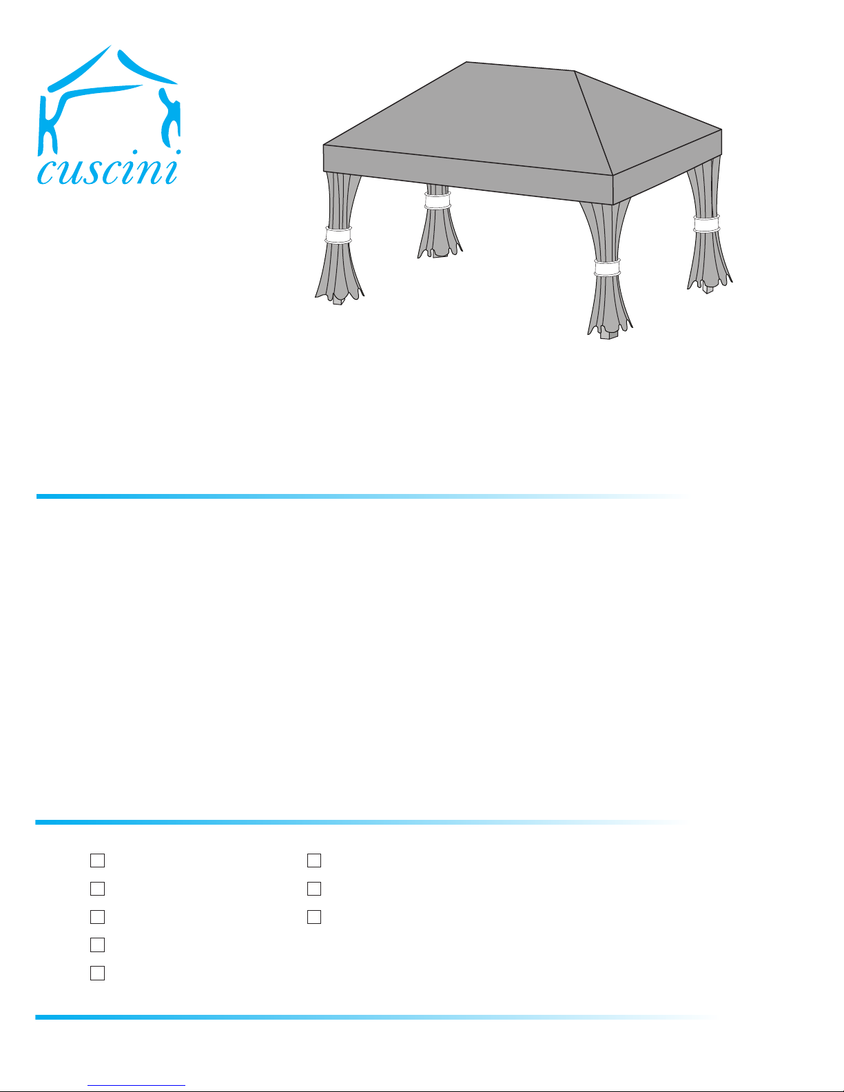
ABRI
Fixed Classic Roof / Single Rail System
Step by Step Assembly Instructions
Before You Begin
These installation instructions will lead you through the process of installing your new shelter. The installation of the shelter
requires special attention to certain detail. Before you begin you should:
CHECK YOUR ORDER. Make sure the contents of the carton match the product numbers on your order. Contact your dealer
if there are any damaged, missing or incorrect parts.
PAY ATTENTION TO SAFETY. Because of the size and weight of certain parts, installation is recommended with no fewer
than two people. Always maintain a clean, organized work area.
MAKE SURE YOU HAVE THE RIGHT TOOLS AND MATERIALS. Jardin de Ville supplies the appropriate fasteners upon
request through your dealer for anchoring the shelter securely to the ground. If you are unsure about the required anchoring
system best suited for your shelter, consult your dealer for the proper fastening method.
REVIEW ENTIRE INSTALLATION GUIDE. This step gives you the opportunity to contact your dealer to answer any
questions before you begin.
Assembly Requirements
Two Persons
Hand Drill
Ladder
Wrench Kit
Tape Measure
Level
Rubber Hammer
Screwdriver Set
of 10
1
Model # Pavillion 1.0Distributor: ShadeScapes Americas 970.527.7070cuscini.shadescapesamericas.com
Page 2
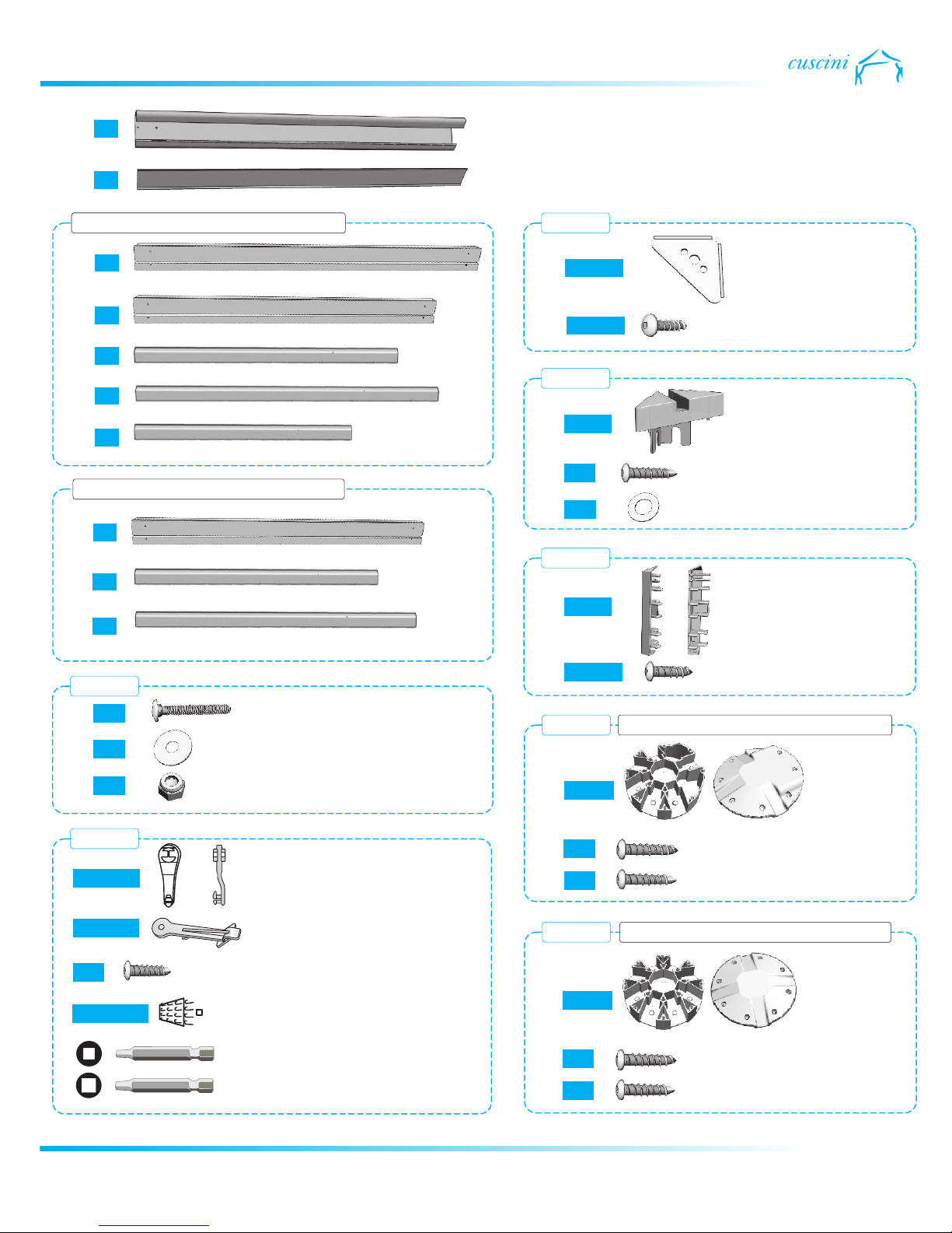
Part List
4x
P1
4x
P2
Supplied with rectangular models
2x B1
12’ or 14’ Side Beam
B2
2x
6x
4x
1x
10’ Side Beam
S1
Roof Side Spoke (punched hole at one end)
S2
Roof Corner Spoke (punched hole at one end)
S3
Roof Middle Support Spoke (both ends with punched holes)
Supplied with square models
4x
B2
10’ Side Beam
4x
S1
Roof Side Spoke (punched hole at one end)
S2
4x
Roof Corner Spoke (punched hole at one end)
Triangular Corner Post
Corner Post Cover
KC12
LA3005
4x
16x
BL3016
KC13
4x
PL110
4x 072
4x 005
KC14
PL103
4x
Post End Plate
End Plate Metal Screw #12-5/8”
Corner Post Top Cover
Self-tapping Screw #8-1”
9/32” x 5/8” Flat Washer
Plastic Corner Beam Inserts
KC15
16x 017
007
16x
16x
012
MISC
K.PL101
K.PL106
054
K.APL001
Carriage Bolt - 5/16” x 1-1/4”
5/16” x 1-1/2” Flat Washer
5/16” Nylon Lock Nut
Pulleys included with curtains
Roof Cover Hook
Self-taping Screw #8-1/2”
Velcro Strips (shipped with decorative curtains)
#8 Square Head Screwdriver Bit*
#10 Square Head Screwdriver Bit*
16x
KC10
2x
16x
6x 040
KC21
1x
8x
4x
BL3015
PL104
062
PL105
062
040
Metal Screw #8-1/2”
Supplied with rectangular models
Roof Joint
Box (2 pieces)
Bottom
Joint Cover Screw #7-3/4”
Self-taping Screw #8-3/4”
Top
Supplied with square models
Roof Joint
Box (2 pieces)
Bottom
Joint Cover Screw #7-3/4”
Self-taping Screw #8-3/4”
Top
*Provided for European countries only
of 10
2
Model # Pavillion 1.0Distributor: ShadeScapes Americas 970.527.7070cuscini.shadescapesamericas.com
Page 3
Getting Started
1
P1
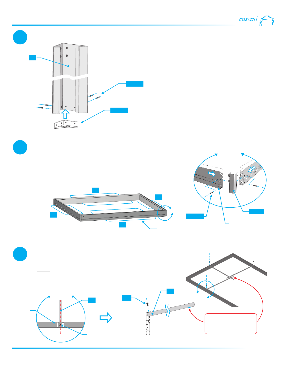
Secure the base plates to the bottom of [KC12.LA3005]
each of the aluminum corner posts using metal screws [P1]
[KC12.BL3016] as shown in the diagram. (Repeat step for all
four corner posts.)
BL3016
LA3005
2
3
On a flat surface, assemble all the beams together by inserting the
plastic corners at each end. Once fully inserted, lock in [KC14.PL103]
place the plastic corners with supplied screws , as [KC14.BL3015]
shown in view A-A. You may use pieces of the cardboard shipping
box to protect the frame from scratches.
B1
B2
B2
B1
Attach all side spokes to the beams of the structure with the (6) [S1]
self-taping screws . Each side spoke should be [(KC10 or KC21).040]
centered between sticker markers on the beams as shown in view B-B.
NOTE that the punched hole end of the spoke should be facing
downwards and away from the beam. (Repeat step on all sides of the
structure.)
A-A
Cardboard
View A-A
PL103
BL3015
Holes used
in step 14
View B-B
Sticker
Markers
Top View
S1
Drilling
Location
040
Profile View
S1
B-B
The punched hole
should be on this
end facing downwards.
of 10
3
Model # Pavillion 1.0Distributor: ShadeScapes Americas 970.527.7070cuscini.shadescapesamericas.com
Page 4
Assembling the Roof
4
5
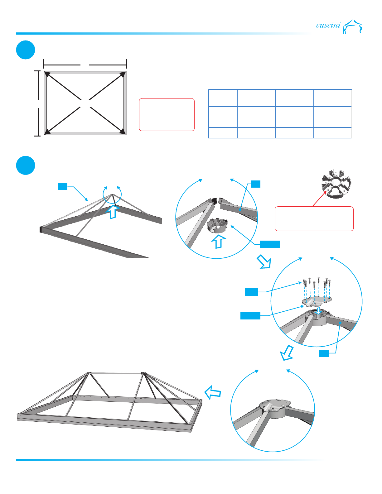
Make sure the frame is well levelled and that corners are set at right angles
as shown in the left hand diagram. Forcing the diagonal in both direction [D]
to be equal will ensure corners are set at right angles. Consult the table
below for external frame dimensions.
Set frame at
right angles
before continuing
assembly.
W
L
D
Top View
RECTANGULAR MODEL (see 6 for square model)
S2
C-C
Raise
Spokes
External
Dimension
W 116 5/8 (296.0) 116 5/8 (296.0) 116 5/8 (296.0)
L 116 5/8 (296.0) 143 3/4 (365.0) 166 3/8 (422.5)
D 164 7/8 (419.0) 185 1/8 (470.0) 203 1/8 (516.0)
View C-C
10x10 Model
inches (cm)
Center Spoke
S3
10x12 Model
inches (cm)
Secure the punched end
of each spokes over the
joint box protrusions.
10x14 Model
inches (cm)
Insert the corner spokes by simply wedging one end into the one-[S2]
inch slot of each corner. Then raise the spoke assembly to fit inside the
plastic joint box as shown in View C-C. Install as well the [KC10.PL104]
center support at this time with the punched holes facing downwards. [S3]
Fit the punched end of the spokes securely over the joint box protrusions
before installing the joint box cap using screws . (Repeat step [KC10.062]
on other side of the structure).
Assembled Roof Framework
PL104
View C-C
062
PL104
S3
Center Spoke
View D-D
of 10
4
Model # Pavillion 1.0Distributor: ShadeScapes Americas 970.527.7070cuscini.shadescapesamericas.com
Page 5
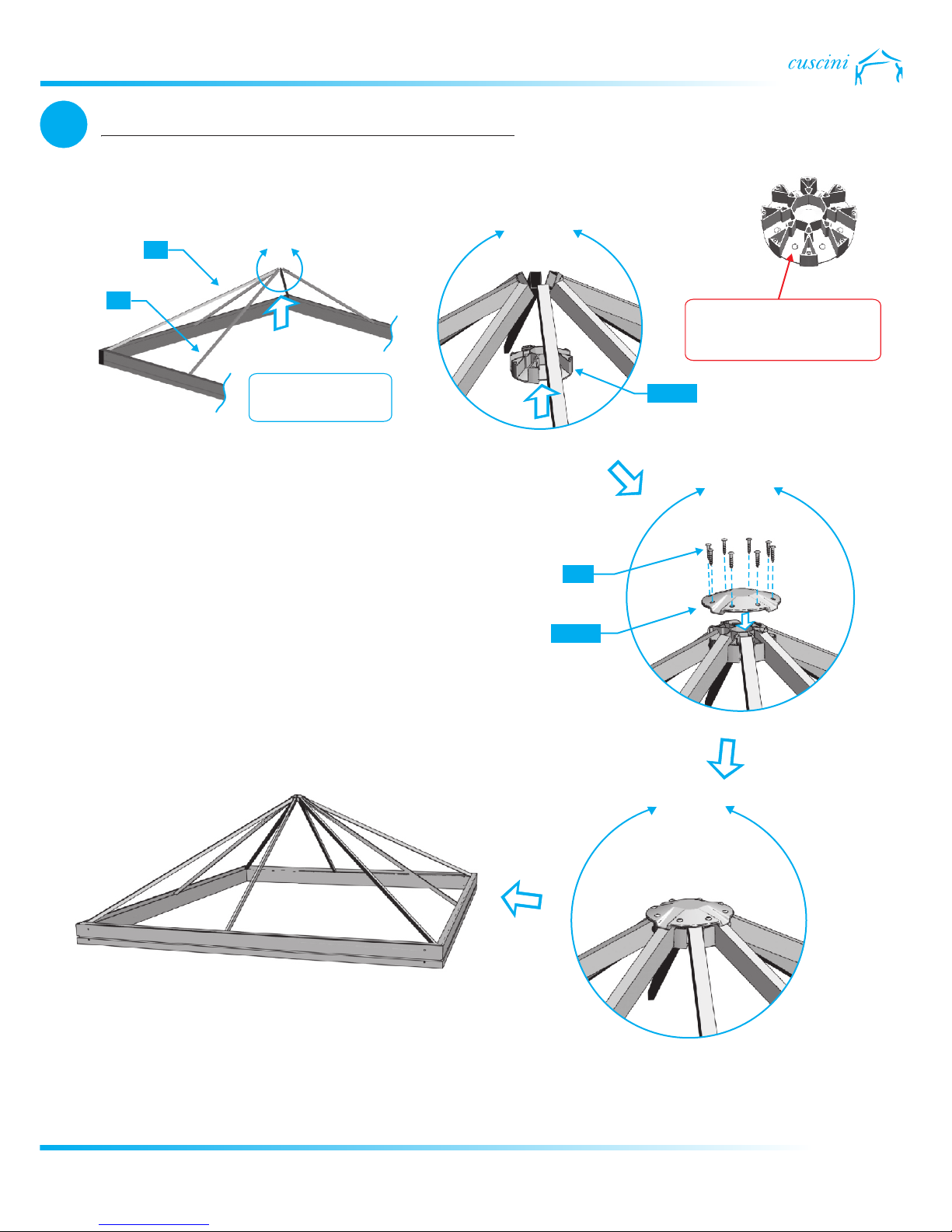
Assembling the Roof
SQUARE MODEL (see 5 for rectangular model)
6
S2
C-C
View C-C
S1
Raise
Spokes
Some spokes
omitted for clarity
Insert the corner spokes by simply wedging one end [S2]
into the one-inch slot of each corner. Then raise the spoke
assembly to fit inside the plastic joint box [KC21.PL105]
as shown in View C-C. Fit the punched end of the spokes
securely over the joint box protrusions before installing the
joint box cap using screws . [KC21.062]
Secure the punched end
of each spokes over the
joint box protrusions.
PL105
View C-C
062
PL105
Assembled Roof Framework
View D-D
of 10
5
Model # Pavillion 1.0Distributor: ShadeScapes Americas 970.527.7070cuscini.shadescapesamericas.com
Page 6
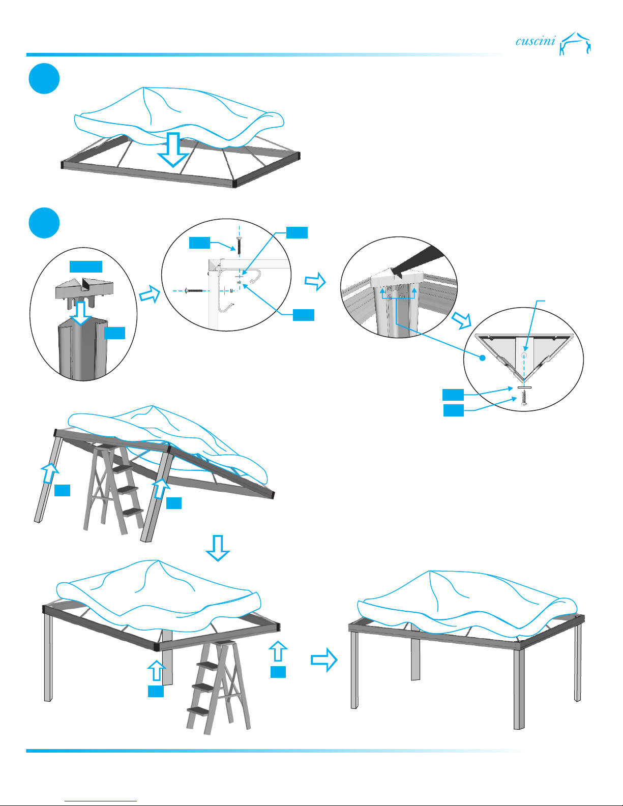
Installing the Corner Posts
7
Lay the roof cover over the top of the frame.
8
P1
PL110
Start
P1
017
Roof truss and cover not
shown for clarity
(TOP VIEW)
P1
007
Flat Washer
Circular
012
Lock-Nut
Assembled
Corner Post
Flat Washer
This step may require a second person or a ladder to lift the roof
assembly in order to fix all four corner posts . Insert the top cover [P1]
[KC13.PL110] [P1] to each corner post as shown in the top left diagram.
Attach one of the four corner posts and its top cover to each corner of
the structure using bolts , washers and lock-nuts [KC15.017] [KC15.007]
[KC15.012] as shown in the upper diagram. Attach all corner spokes
[S2] [KC13.PL110] to the plastic covers with the (4) self-tapping screws
[KC13.072] [KC13.005] and flat washers . The screws are installed
underneath the plastic covers at the circular mark location. See diagrams
below for assembly steps.
005
072
Corner Top Cover
Bottom View
Mark
P1
P1
of 10
6
Model # Pavillion 1.0Distributor: ShadeScapes Americas 970.527.7070cuscini.shadescapesamericas.com
Page 7
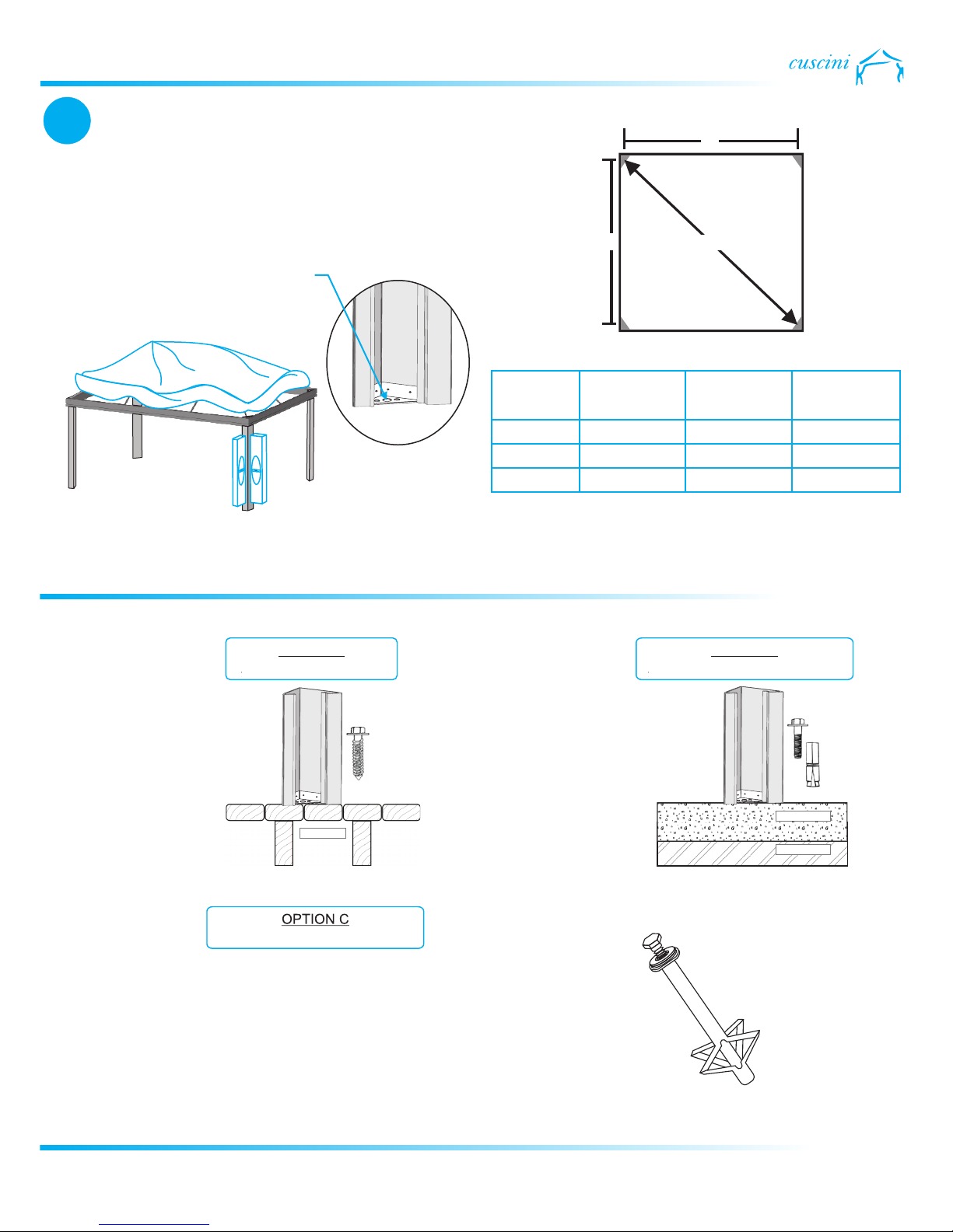
Archoring the Shelter
9
Make sure the structure is well aligned and levelled with
the floor as shown in the diagram below. Consult the
section below for recommendations on the type of
anchorage required for fixing the structure on the floor.
Remaining holes in plate [LA3005]
are used for fixing the
structure on the floor
level
L
Internal
Dimension
W
L
D
W
10x10 Model
inches (cm)
D
10x12 Model
inches (cm)
113-3/4 (289.0)113-3/4 (289.0) 113-3/4 (289.0)
140-3/4 (357.5)113-3/4 (289.0) 163-3/8 (415.0)
181 (459.5)160-7/8 (408.6) 199-1/8 (505.5)
Dimensions given from center to center
of plates [LA3005]
10x14 Model
inches (cm)
Structure Anchorage System Recommendations
OPTION A
WOOD DECK/FLOOR
Requirements:
8 (2 per plates) of each
- 5/16" x 2" wood screws
- 5/16" washers
WOOD
PAVER/GRASS
This anchoring system is the recommended solution for
anchoring your tent on other surfaces than wood or concrete
such as paver or grass. Consult your dealer for more
information on this fastening method.
Requirements:
8 (2 per plates) of each
- 3/8" x 1-1/2" expansion anchor
* use 1/2" cement drill bit
OPTION B
CONCRETE/CEMENT FLOOR
CONCRETE
SOIL
of 10
7
Model # Pavillion 1.0Distributor: ShadeScapes Americas 970.527.7070cuscini.shadescapesamericas.com
Page 8
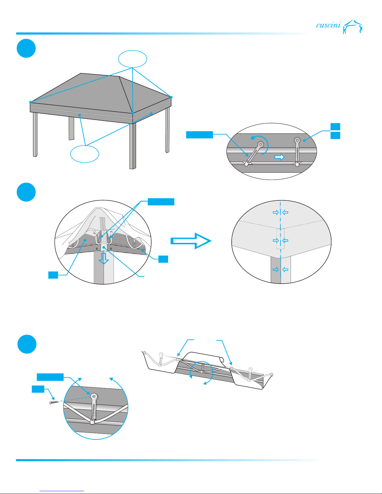
Final Frame Assembly
centerline
10
11
Step 12
Sides
Step 11
Corners
K.PL106
The roof awning fabric is attached to the structure with the
hooks provided. The hooks are inserted and [MISC K.PL106]
secured in place in the beam slots as shown in the diagram
below. Install first two hooks in each corners (Step 11) then
work your way around the sides installing hooks between
each eyelets (Step 12). Once all the hooks are positioned
correctly secure them to the beams with the self-tapping
screws (Step 12 View F-F). [MISC 054]
B1
K.PL106
B2
B2
B1
When installing the roof cover and hooks at each corner make sure that the nylon webbing from [MISC K.PL106]
the roof cover, elastic and hooks are placed as shown in the left diagram above. This step will ensure that the
elastic remains in position when tension is applied. Once the roof cover is in place, verify that its corner is aligned
with the corner of the structure as shown in the right diagram above.
Place the nylon webbing over
the beam corner and under the elastic
Eyelet
12
K.PL106
054
View F-F
F-F
Complete securing the awning fabric to the structure by installing
remaining hooks on all fours sides as shown in the [MISC K.PL106]
diagram. Work your way progressively around the structure to produce an
even tension in the elastic.
of 10
8
Model # Pavillion 1.0Distributor: ShadeScapes Americas 970.527.7070cuscini.shadescapesamericas.com
Page 9
Installing the Roof Fabric
13
14
Roof truss not shown for clarity
K.PL101
Plastic Pulley
Metallic
Eyelet
P2
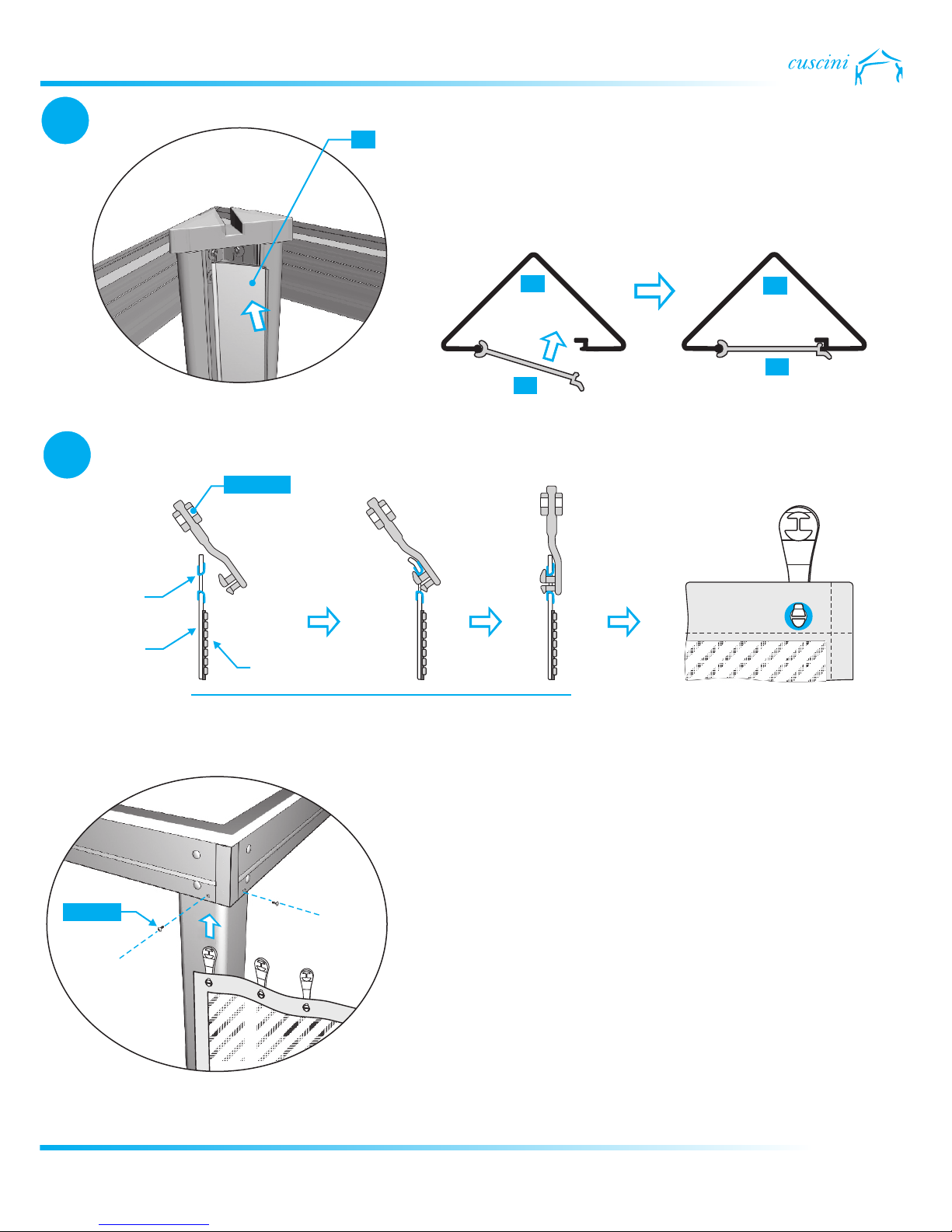
To complete the post assembly, snap together the corner posts
[P1] [P2] and corner post covers using a rubber hammer as
shown in the diagrams above. Repeat step for each corner.
Snap Pulley
in place
P2
P1
Top View
Curtain
Exterior Side
P1
P2
Curtain
(Exterior Side)
BL3015
Zipper
(Interior Side)
Profile View
Install plastic pulleys by snapping them in each [MISC K.PL101]
metallic curtain eyelet. Pulleys should be facing towards the
curtain side on which the zipper is located (see above steps).
Then install each curtain sections into the provided beam slots
as shown by left hand diagram. After installing all pulleys, block
the access with the screws as shown in the [KC14.BL3015]
diagram. Repeat step for each corner. See next step (15) for
curtain installation example.
of 10
9
Model # Pavillion 1.0Distributor: ShadeScapes Americas 970.527.7070cuscini.shadescapesamericas.com
Page 10
Installing the Curtains
15
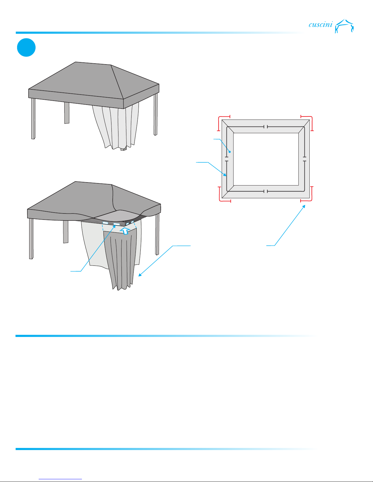
Complete installation of each curtain sections as shown
by example in the left hand diagram.
beam rail
Velcro Strips
Bottom Groove
12” (30.5cm) apart
plastic curtains
The optional decorative curtains are installed using
velcro strips inserted 12” (30.5cm) [MISC K.APL001]
apart in the bottom groove of the beams. Repeat on all
four corners.
TOP VIEW
Optional decorative curtains
(installed using velcro strips
on bottom beam groove)
Distributor: ShadeScapes Americas
970.527.7070
cuscini.shadescapesamericas.com
[email protected]
[email protected]
of 10
10
Model # Pavillion 1.0Distributor: ShadeScapes Americas 970.527.7070cuscini.shadescapesamericas.com
 Loading...