

Curtron CFD-TQ-2-36-1, CFD-TQ-2-42-1, CFD-TQ-2-48-1, CFD-TQ-2-60-1, CFD-TQ-3-60-1 Installation Manual
...Page 1
800•833•5005
Curtron Products • 5350 Campbells Run Road • Pittsburgh, PA 15205-9738 • 412.787.9750
• Fax: 412.787.3665 • Web Site: www.curtronproducts.com • E-Mail: info@curtronproducts.com
OTHER
CURTRON
PRODUCTS
POLAR-PRO™
SWINGING DOORS
CASER
COOLER CURTAINS
CURTRONIZER
™
STRIP DOORS
TEMP KEEPERS™
COOL KEEPERS
™
STRIP DOORS
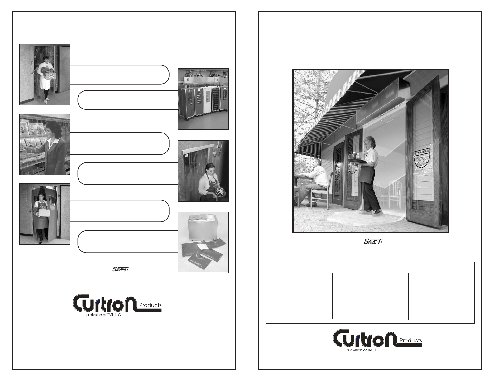
Make Food Products
Your Number One Priority!
RACK COVERS
MODEL ENCLOSED:
❏ CFD-TQ-2-36-1
❏ CFD-TQ-2-42-1
❏ CFD-TQ-2-48-1
❏ CFD-TQ-2-60-1
❏ CFD-TQ-3-60-1
❏ IBD-TQ-2-36-1
❏ IBD-TQ-2-42-1
❏ IBD-TQ-2-48-1
❏ IBD-TQ-2-60-1
❏ IBD-TQ-3-60-2
❏ CFD-HH-2-36-1-3S
❏ CFD-HH-2-42-1-3S
❏ CFD-HH-2-48-1-3S
❏ CFD-HH-2-60-1-3S
❏ CFD-HH-3-60-1-3S
INSTALLATION INSTRUCTIONS
AIR DOORS
Make Food Products
Your Number One Priority!
Copyright © 2007 Curtron Products Catalog No. CFD/IBDAD 06-07
Page 2
2
3
Thank you for choosing a Curtron quality product.
UNCRATING
Carefully examine the carton(s) for damage before opening. If the carton is
damaged, immediately notify the shipping company.
• Remove all protective packaging.
• Remove the cover housing by lifting vertically.
Enclosed is a packet of self-tapping screws which will be used to attach the
cover housing to the mounted chassis.
CAUTION: LIFT THE UNIT BY GRASPING THE INLET RINGS ON THE
BLOWER HOUSING WITHOUT TOUCHING THE BLOWER WHEELS.
Excess weight on the blower wheels may cause improper alignment and balance of the motor shaft and blower wheels.
WARNING:TO REDUCE THE RISK OF FIRE, ELECTRIC SHOCK, OR
INJURY TO PERSONS, OBSERVE THE FOLLOWING:
A. Use this unit only in the manner intended by the manufacturer. If you
have any questions, contact the manufacturer.
B. Before servicing or cleaning unit, switch power off at the service panel
and lock service panel to prevent power from being switched on accidentally.
C. Installation work and electrical wiring must be done by a qualified person
in accordance with all applicable codes and standards, including firerated construction.
D. When cutting or drilling into wall or ceiling, do not damage electrical wiring
and other hidden utilities.
E. Do not operate this fan with any solid state speed control device.
INDOOR AND OUTDOOR MOUNTING FOR CURTRON AIR DOORS
INDOOR MOUNTING - Environmental/Insect/ Dust Control
OUTDOOR MOUNTING - Insect/ Dust Control
NOTE: The air door is weatherproof; therefore, no special covering is required
for outdoor mounting.
IMPORTANT: A minimum of 4” is required above the top of the air door for the
installation and removal of the cover housing.
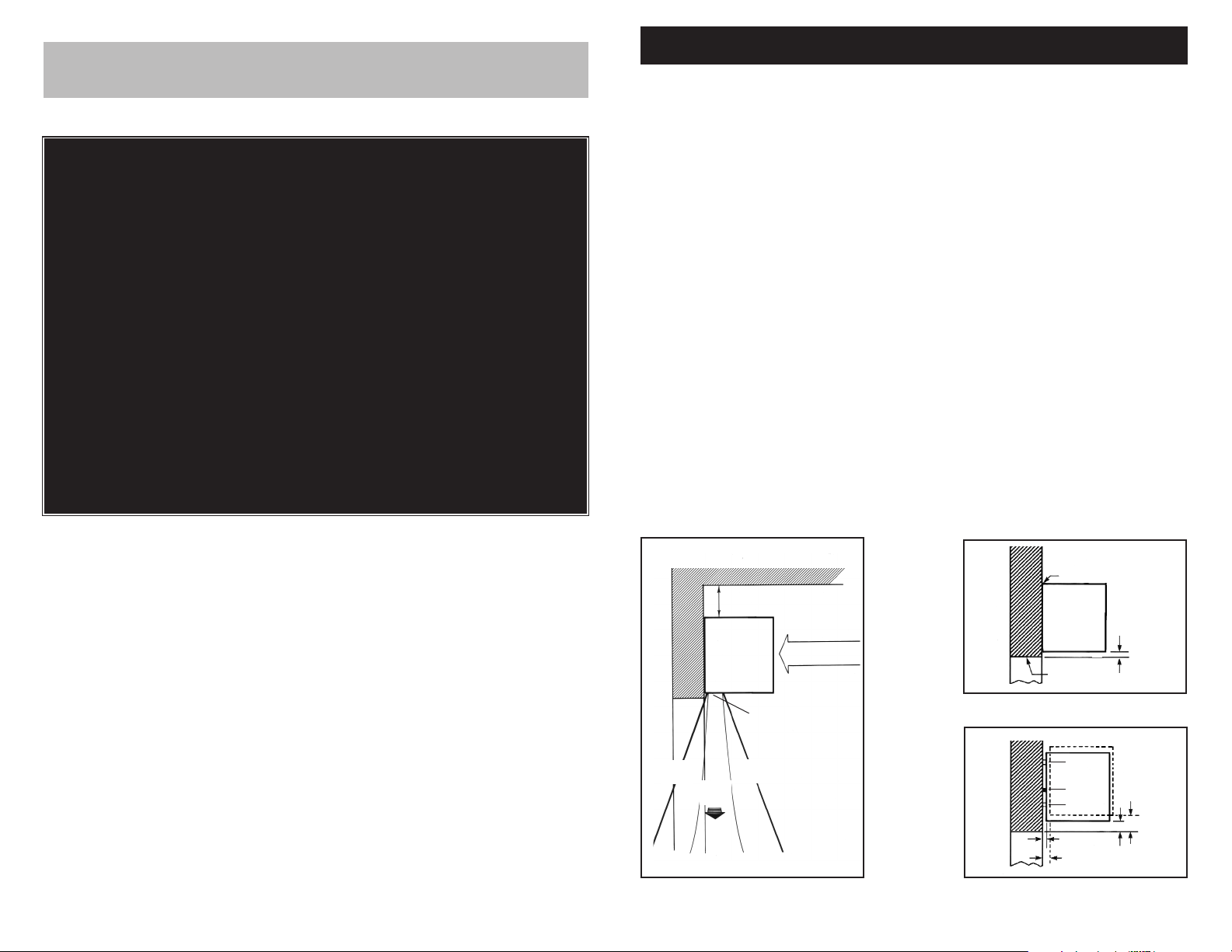
1. Install the air door so that nothing interferes with the air stream when it is
deflected 20° to either side. If the air stream strikes any obstruction, for
example, the top edge of the doorway, a structural beam or a door opening
device, its efficiency will be reduced. See Figure 1. On electrically heated
units there should be a minimum clearance of at least 4” between the side
of the unit and any combustible material, if the unit is enclosed in the ceiling
or a decorative cover.
2. The outlet nozzle should be no more than 1” above the top of the doorway
opening. See Figure 2A.
If the air door must be mounted higher, then it should be spaced out from
the wall 3/8” for every inch the unit is moved up above the doorway opening. Any void between the air door and the wall must be sealed (use foam,
plastics or similar packing) for best performance. See Figure 2B.
Figure 1
Figure 2B
Figure 2A
FLUSH MOUNT
AIR
DOOR
1”
TOP OF
DOORWAY
3”
2”
SPACER
SEAL
SPACER
3/8”
3/4”
4” MINIMUM SPACE REQUIRED
AIR INTAKE
AIR
DOOR
AIR
FLOW
MAX.
20°
MAX.
20°
OUTLET NOZZLE
Page 3

4
5
MOTOR /BLOWER MOUNTING
Drill and install the mounting hardware (supplied by others). The keyhole slots in the backplate accommodate 1/4” mounting hardware.
See Figure 4.
3. Do not fully tighten the mounting screws.
4. Lift the motor/blower assembly by the sheet
metal frame over the door with the outlet
nozzle facing down. DO NOT LIFT BY THE
BLOWER WHEELS.
5. Slip the motor/blower
assembly over the 4
mounting screws.
6. Tighten the 4 mounting screws for a
secure attachment.
See Figure 5.
7. Replace cover with
sheet metal screws.
AIR DOOR
BACKPLATE
8 KEYHOLE
MOUNTING SLOTS
Figure 3
Select and mark two vertical holes on each end of the backplate. See Figure 3.
The mounting holes and hardware must be capable of supporting a minimum
of three times the net weight of the air door.
See Table 1.
If sufficient support is not available, go to Optional Mounting.
AMBIENT ELECTRIC
MODEL NET WEIGHT NET WEIGHT
LBS. LBS.
TABLE 1
CFD-TQ-2-36-1 70 75
CFD-TQ-2-42-1 80 85
CFD-TQ-2-48-1 82 87
CFD-TQ-2-60-1 97 102
CFD-TQ-3-60-1 110 115
1/4”
1/4”
Figure 5
LINE-UP KEYHOLES ON
ALL 4 SCREWS
PUSH
BACKPLATE
TOWARD WALL
SLIDE BACKPLATE DOWN
TIGHTEN ALL
4 SCREWS
If the location of the keyhole slots on the backplate do not provide suitable
support, locate and mark the best alternative location on the wall.
Transfer the marks to the backplate of the air door.
Before drilling holes in the backplate of the air door, check to make sure the
new holes will not interfere with the internal components of the air door.
Drill the 4 holes in the wall and 4 holes in the backplate.
Lift the motor/blower assembly by the sheet metal frame over the door with
the outlet nozzle facing down. DO NOT LIFT BY THE BLOWER WHEELS.
Install the 4 mounting screws (supplied by others).
OPTIONAL MOUNTING
ELECTRIC WIRING
CAUTION: Electrical Shock Hazard
Disconnect power source whenever working on unit. WARNING: To
reduce risk of fire or electric shock, DO NOT use this fan with any
solid state speed control device.
1. Make sure the correct voltage, as marked on the unit, is used.
2. Connect the proper size conductor wire (supplied by others) to the pigtail
leads in the junction box.
See Figure 6. For motor amp ratings see Table 2.
3. Connect conductor wire to power source.
4. An optional knock-out is supplied on the left-hand side of the cover housing to connect wiring from the left-hand side.
Figure 6
Table 2
Weights are the same for comparable
length units in CFD-HH and IBD-TQ Series
Figure 4
JUNCTION BOX
Standard Amps for Amps for
Motor Voltages1/2 Motor3/4 Motor
120, 1ø, 60 hz 7.2 7.5
208, 1ø, 60 hz 4.0 3.8
240, 1ø, 60 hz 4.0 3.8
460, 1ø, 60 hz N/A 1.8
Page 4

6
The heater circuit may be controlled by a remote
thermostat or a remote mounted three position fan only/off/fan with heat. See Figure 7.
Connect the proper wires (located in the junction
box) to the terminals of the thermostat or three
position switch. See wiring diagram located in
the inside of the cover housing. See Figure 8.
Overheating protection is provided by thermal
cutouts built into the heater coil assembly.
ELECTRICALLY HEATED MODELS
Remote Thermostat Or
Remote Three Position
Switch
Figure 7
Figure 8
IMPORTANT: All electrical wiring
should be performed by qualified
personnel and done in accordance
with local codes and regulations.
CAUTION: Disconnecting more than one power supply
may be required to de-energize the unit.
Table 3
Aluminum
Cover Housing
Bottom 4
Housing
Screws
Motor/Blower
Assembly
Power
Source
Wires
Top 4 Housing Screws
AMP DRAW OF ELECTRIC HEAT
Voltage
7.5 kw 10 kw 15 kw
208v 1ø - 60 hz 36.1 48.0 72.0
240v 1ø - 60 hz 31.4 41.7 62.5
208v 3ø - 60 hz 20.9 27.8 41.6
240v 3ø - 60 hz 18.1 24.1 36.1
480v 3ø - 60 hz 9.0 12.0 18.0
Note: When amp draw of motors and heaters are in
excess of 48 amps, two power supplies are required.
7
AIR DIRECTIONAL VANES ADJUSTMENT
AIR FLOW ADJUSTMENTS
Adjustment of the air directional vanes may be made by grasping each vane with
pliers or channel locks and twisting. It is recommended to place a rag or newspaper between the plier jaws and the vanes to prevent scratching.
If the vanes will not twist with a pair of pliers, it may be necessary to remove the
cover housing and loosen the 2 vane mounting screws located on each end of the
outlet nozzle. ALWAYS DISCONNECT THE POWER SOURCE BEFORE
REMOVING THE COVER.
1. With the air door operating and door in its full open position, check to
see that nothing is obstructing the air flow at the discharge nozzle.
2. Find the air stream split location. Hold a handkerchief, by the corner,
approximately 12” above the floor. Gently move the handkerchief back
and forth in the doorway. Make sure the air is being directed to both the
inside and outside. See Figure 9. The split location is indicated when the
handkerchief is vertical with minimal or no fluttering. See Figure 9.
3. FOR INDOOR MOUNTING - The split location should be approximately
3” outside the doorway and 12” above the floor. See Figure 10.
4. FOR EXTERIOR MOUNTING - The split location should be approxi-
mately 6” outside the doorway and 12” above the floor. See Figure 11.
OUTSIDE INSIDE
12” Minimum
Figure 9 Figure 10
Figure 11
INSIDE
INSIDE
OUTSIDE
OUTSIDE
12” Above
Floor
12” Above
Floor
3”
6”
Page 5

8
OPTIONAL CONTROLS
If an automatic door switch (rated at 22 amps) or a start/stop push button station (rated at 24 amps) is used, refer to the wiring diagram found on the inside
of the housing for proper wiring.
CAUTION: disconnect the main power supply before installing the cover.
When the installation of the motor/blower section and wiring is complete, slide the
cover over the assembly and fasten with the 8 screws that are provided: 4 on the
top and 4 on the bottom. finally, connect the main power supply. See Figure 8.
WARNING: The motor has internal self-resetting thermal overload protection. Always disconnect the power source before servicing.
MOTOR /BLOWER WHEEL ASSEMBLY/COVER HOUSING
To keep your Curtron Air Door operating at peak efficiency, semi-annual
cleaning of the blower wheels and cover housing is recommended. The
housing can easily be removed for access to the motor/blower assembly by
removing the cover housing screws. See Figure 8. Remove dust and dirt
build-up from the blower wheels and housing. The motor is totally enclosed
and permanently lubricated, and does not require any additional lubrication.
Re-install the cover housing and housing screws after maintenance is complete.
ALUMINUM AIR FILTER
Every Curtron Air Door comes with a built-in re-usable Aluminum Air Filter
which should be cleaned twice a year. Simply remove the intake grill mounting screws and detach the grill from the cover housing. The filter can then
be easily lifted out of the frame. Clean with soap and water and allow to dry
before placing the filter back into the frame. Replace the intake grill and
mounting screws. See Figure 12.
NOTES:
MAINTENANCE AND CLEANING
Model No.
Serial No.
Date of Purchase
INTAKE GRILL
MOUNTING
SCREWS
INTAKE GRILL
MOUNTING SCREWS
INTAKE GRILL
RE-USABLE
ALUMINUM AIR FILTER
COVER
HOUSING
Figure 12
 Loading...