

Page 1

5
Cleaning the Oven Curtain is extremely simple. Remove each
panel separately and wash with soap and water in a utility tub or
on a flat surface. After cleaning, rehang each panel in its appropriate area.
DO NOT use abrasive cleaning agents or scouring pads.
Using mild soap or liquid detergent with soft sponge or washcloth
is preferred.
NOTES:
CLEANING
Page 2
INSTALLATION INSTRUCTIONS
800•833•5005
Curtron Products • 5350 Campbells Run Road • Pittsburgh, PA 15205-9738 • 412.787.9750
• Fax: 412.787.3665 • Web Site: www.curtronproducts.com • E-Mail: info@curtronproducts.com
COOLKEEPER
™
OVEN CURTAINS
OTHER
CURTRON
PRODUCTS
POLAR-PRO™
SWINGING DOORS
CASER
COOLER CURTAINS
CURTRONIZER™
STRIP DOORS
STRIP DOORS
Make Food Products
Your Number One Priority!
AIR DOORS
Make Food Products
Your Number One Priority!
RACK COVERS
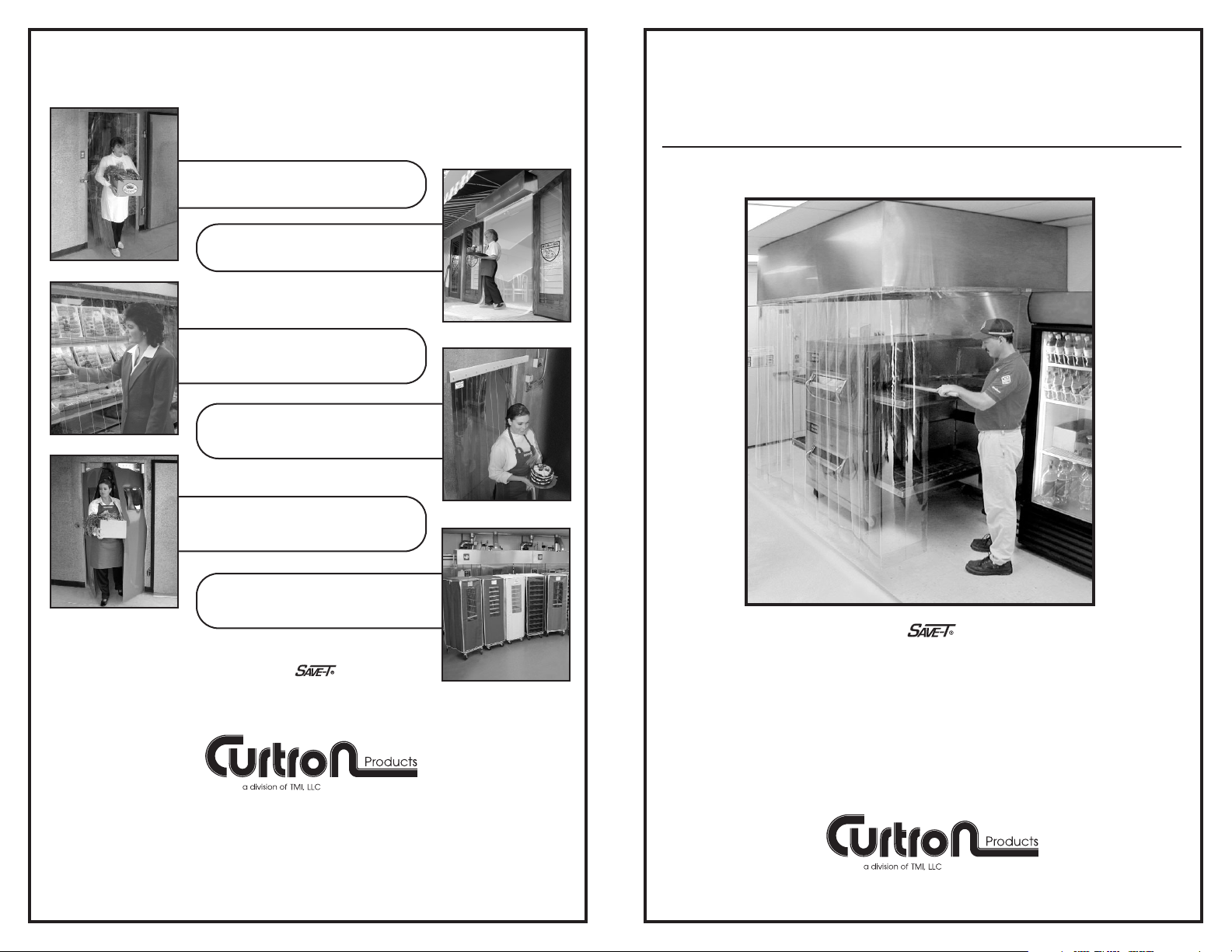
Your Coolkeeper creates a
thermal barrier by attaching flexible PVC
panels to the oven’s exhaust hood.
Copyright © 2007 Curtron Products Catalog No. II-CKOC 06-07
Page 3

Each Oven Curtain is
made to your specific
dimensions and consists of multiple sections of clear flexible
PVC. Your exhaust
hood has either three
exterior surfaces (A, B,
C) or four surfaces (A, B, C, D) (See
Fig. 1). Sides A and B have 3 separate sections. Side C could be one
piece or 3 sectional pieces if the
oven is equipped with Side Doors.
TO INSTALL
2 3
Each panel is clearly marked with a label, indicating the proper side and section. Also, each
panel has a Velcro strip attached to its top edge.
There is a corresponding piece of Velcro (the
other half) that has been cut to size and is unattached. Each loose piece of Velcro should be
attached to its corresponding PVC panel. (See
Fig. 2). NOTE: At this point . . . DO NOT REMOVE
THE PRESSURE SENSITIVE BACKING.
Finally, hold Panel “A2” against the
hood, so the bottom edge aligns
with the side marks and mark the
hood at the top of the panel.
Remove the Velcro pressure sensitive backing and attach the panel
to the hood. (See Fig. 6)
First, on the “A” side of the
hood, hold Panel “A1” against
the hood, making sure that the
left edge of the panel is flush
with the left edge of the hood.
(See Fig. 3). The bottom of the
panel should be approximately
1'' from the floor. Mark the hood
at the right edge and top of the
panel. Remove the Velcro pressure sensitive backing and
attach the panel to the hood.
Second, place Panel “A3” against
the right edge of the hood, 1''
above the floor and mark the
hood at the left edge and top of
the panel. (See Fig. 4). Again,
remove the Velcro pressure sensitive backing and attach the
panel to the hood.
Next, measure the distance from
the floor to 1'' above the top
“conveyer tunnel’s” top edge.
Mark that measurement on the
side of each mounted panel (A1
& A3). (See Fig. 5).
A Side
A1 A2 A3
B Side
B1 B2 B3
D Side
F
or 4 sided
enclosures only!
C Side
C1 C2 C3
Sections
applicable if oven
has Side Doors
HOOD
Fig. 1
Loose piece
of Velcro
Velcro attached
to panel
Pressure
sensitive
backing
Fig. 2
Fig. 3
Fig. 4
Fig. 5
Fig. 6
Velcro
HOOD
Mark
Panel
A1
1”
up off
floor
Panel
A3
HOOD
Mark
Mark
Measurement
Panel
A1
Panel
A3
Measure
Floor
Panel
A2
Mark
1”
up off
floor
1”
up off
floor
OVEN
TUNNEL
A
Side
A
Side
Velcro
A
Side
1” Above
Tun nel
A
Side
Page 4

Following this same procedure,
continue to Side “B”. First,
attach Panel “B1”, then Panel
“B3” (see Fig.7). Next, measure the distance from the floor
to 1” above the top “side doors”
top edge (if applicable). Mark
that measurement on the side
of each mounted panel (B1 &
B3), (same as Side “A”). If the
oven is not equipped with Side
Doors, there will be just one
panel (B1) to attach.
Side “C” panels (Fig. 8) should
be attached in the same manner as Side “A”.
Fig. 7
Panel
B1
HOOD
B-Side
Panel
B3
Mark
Measurement
Fig. 8
HOOD
Panel
C1
Panel
C3
And finally, if your oven
exhaust hood has four (4)
exterior sides, Side “D” should
be attached to the hood, so the
panel stretches edge-to-edge,
approximately 1” from the floor.
Fig. 9
Floor
HOOD
Measure
B
Side
1”
up off
floor
C
Side
1”
up off
floor
D
Side
1”
up off
floor
4
 Loading...