

Curtis Instruments PMC 1200, PMC 1209B, PMC 1221C, PMC 1231C, PMC 1221B Series Manual
1209B/1221B
1221C/1231C
© 1999 CURTIS INSTRUMENTS, INC.
DESIGN OF CURTIS PMC 1200 SERIES
CONTROLLERS PROTECTED BY U.S.
PATENT NO. 4626750.
MOTOR CONTROLLERS
1209B/1221B/1221C/1231C Manual
p/n 98827, Rev. D: August 1999
MANUAL
CURTIS PMC
235 East Airway Boulevard
Livermore, California 94568 USA
Tel: 925-961-1088
Fax: 925-961-1099
www.curtisinst.com

1209B / 1221B / 1221C / 1231C Manual
p/n 98827, Rev. D: August 1999
© 1999 CURTIS INSTRUMENTS, INC.
This electronic version of the 1209B/1221B/1221C/1231C manual is offered as a
convenience to our customers. You may download any or all of it.
If you would like a hard copy of the published manual, please order it by part number from
the Curtis office nearest you.
The electronic version of the manual is identical to the printed version published in August
1999. Bookmarks have been added to the electronic version to speed the process of going
directly to a particular part of the document.
CURTIS INSTRUMENTS, INC.
200 KISCO AVENUE
MOUNT KISCO, NEW YORK 10549 USA
☎
914-666-2971 FAX 914-666-2188
■ CURTIS PMC
235 EAST AIRWAY BOULEVARD
LIVERMORE, CALIFORNIA 94550 USA
☎
925-961-1088 FAX 925-961-1099
■
ADDITIONAL OFFICES located in
Bulgaria, China, England, France, Germany,
India, Italy, Japan, Netherlands, Puerto Rico,
Russia, Sweden, and Switzerland

Curtis PMC 1209B/1221B/1221C/1231C Manual iii
234567890
1
234567890
1
234567890
1
234567890
1
234567890
1
234567890
1
234567890
1
234567890
1
234567890
1
234567890
1
234567890
1
234567890
1
234567890
1
234567890
1
234567890
1
234567890
1
234567890
1
234567890
1
234567890
1
234567890
1
234567890
1
234567890
1
234567890
1
234567890
1
234567890
1
234567890
1
234567890
1
234567890
1
234567890
1
234567890
1
234567890
1
234567890
1
234567890
1
234567890
1
234567890
1
234567890
1
234567890
1
234567890
1
234567890
1
234567890
1
234567890
1
234567890
1
234567890
1
234567890
1
234567890
1
234567890
1
234567890
1
234567890
1
234567890
1
234567890
1
234567890
1
234567890
1
234567890
1
234567890
1
234567890
1
234567890
1
234567890
1
234567890
1
234567890
1
234567890
1
234567890
1
234567890
1
234567890
1
234567890
1
234567890
1
234567890
1
234567890
1
234567890
1
234567890
1
234567890
1
234567890
1
234567890
1
234567890
1
234567890
1
234567890
1
234567890
1
234567890
1
234567890
1
234567890
1
234567890
1
234567890
1
234567890
1
234567890
1
234567890
1
234567890
1
234567890
1
234567890
1
234567890
1
234567890
1
234567890
1
234567890
1
234567890
1
234567890
1
234567890
1
234567890
1
234567890
1
234567890
1
234567890
1
234567890
1
234567890
1
234567890
1
234567890
1
234567890
1
234567890
1
234567890
1
234567890
1
234567890
1
234567890
1
234567890
1
234567890
1
234567890
1
234567890
1
234567890
1
234567890
1
CONTENTS
1. OVERVIEW .......................................................................1
2. HARDWARE INSTALLATION ....................................... 3
Controller .................................................................... 3
Throttle ........................................................................ 5
Other Hardware ...........................................................8
Main contactor ................................................... 10
Forward/reverse contactors .................................. 11
Forward/reverse switches ..................................... 11
Keyswitch and interlocks .....................................11
Keyswitch relay ................................................... 11
Polarity protection diode ..................................... 12
Control wiring fuse ............................................. 12
Power wiring fuse ................................................ 12
3. WIRING ........................................................................... 13
Connections: Low Current ......................................... 13
Connections: High Current ....................................... 13
Wiring: Typical Installation ....................................... 14
KSI wiring .......................................................... 15
Forward/reverse wiring ........................................ 16
Plug braking ................................................ 16
Freewheeling ................................................16
Throttle wiring ................................................... 17
Standard potbox wiring ...............................17
Pots for twist-grip throttles .......................... 18
Electronic throttle wiring ............................. 19
Reduced speed operation ............................. 20
Throttle ramp shaping ................................. 21
Installation Checkout ................................................. 22
CONTENTS

Curtis PMC 1209B/1221B/1221C/1231C Manual iv
CONTENTS
23456789
0
23456789
0
23456789
0
23456789
0
23456789
0
23456789
0
23456789
0
23456789
0
23456789
0
23456789
0
23456789
0
23456789
0
23456789
0
23456789
0
23456789
0
23456789
0
23456789
0
23456789
0
23456789
0
23456789
0
23456789
0
23456789
0
23456789
0
23456789
0
23456789
0
23456789
0
23456789
0
23456789
0
23456789
0
23456789
0
23456789
0
23456789
0
23456789
0
23456789
0
23456789
0
23456789
0
23456789
0
23456789
0
23456789
0
23456789
0
23456789
0
23456789
0
23456789
0
23456789
0
23456789
0
23456789
0
23456789
0
23456789
0
23456789
0
23456789
0
23456789
0
23456789
0
23456789
0
23456789
0
23456789
0
4. MAINTENANCE AND ADJUSTMENT ....................... 24
Controller .................................................................. 24
Potbox ........................................................................ 25
5. TROUBLESHOOTING AND BENCH TESTING ....... 27
Operational Notes ......................................................27
In-Vehicle Diagnostic Tests (Troubleshooting) .......... 28
Bench Testing ............................................................ 34
6. GLOSSARY: FEATURES AND FUNCTIONS .............. 37
APPENDIX A Functional Description ................................ A-1
APPENDIX B Pulse Width Modulation ............................. B-1
APPENDIX C Electrical Specifications ................................ C-1

Curtis PMC 1209B/1221B/1221C/1231C Manual v
FIGURES
FIG. 1: Curtis PMC 1209B full-feature
motor controller ......................................................... 1
FIG. 2: Mounting dimensions,
Curtis PMC 1209B/1221B/1221C controllers ........... 3
FIG. 3: Mounting dimensions,
Curtis PMC 1231C controller ................................... 4
FIG. 4: Mounting dimensions,
Curtis PMC potboxes PB-5, -6, -9, and -10 ............... 6
FIG. 5: Mounting dimensions, Curtis PMC footpedal ........... 6
FIG. 6: Mounting dimensions,
Curtis electronic throttle (ET series) ........................... 7
FIG. 7: Typical installation,
1209B/1221B/1221C controllers ............................... 8
FIG. 8: Typical installation, 1231C controller ........................9
FIG. 9: Basic wiring configuration,
1209B/1221B/1221C controllers ............................. 14
FIG. 10: Basic wiring configuration, 1231C controller ........... 15
FIG. 11: Control wiring for inhibiting plug braking,
in order to allow freewheeling .................................. 17
FIG. 12: Standard throttle pot, 0–5kΩ ................................... 17
FIG. 13: Bi-directional twist-grip throttle with
a standard 20 kΩ pot and a controller
with the optional 5kΩ–0 throttle input .................... 18
FIGURES

Curtis PMC 1209B/1221B/1221C/1231C Manual vi
FIGURES/TABLES
FIG. 14: Curtis electronic throttle (ET series)
with a controller having the optional
0–5V throttle input .................................................. 19
FIG. 15: Reduced speed operation (with standard
(0–5kΩ pot) ............................................................. 20
FIG. 16: Throttle ramp shapes ................................................21
FIG. 17: Adjustment pots ....................................................... 25
FIG. 18: Guide to troubleshooting procedures ....................... 29
FIG. 19: Setup for bench testing ............................................. 35
FIG. A-1: Block diagram, Curtis PMC
1209B/1221B/1221C/1231C controllers ............... A-1
FIG. B-1: Pulse width modulation.......................................... B-1
TABLES
TABLE 1: Recommended precharge resistors ......................... 10
TABLE C-1: Electrical specifications, 1209B/1221B ............... C-1
TABLE C-2: Electrical specifications, 1221C/1231C ............... C-2
Curtis PMC 1209B/1221B/1221C/1231C Manual
1
OVERVIEW
OVERVIEW
Curtis PMC Model 1209B/1221B and 1221C/1231C electronic motor speed
controllers are designed to provide smooth, silent, cost-effective control of motor
speed and torque on a wide variety of electric vehicles. The 1209B/1221B
controllers are designed primarily for material handling applications, and the
1221C/1231C controllers for on-road vehicles.
Like all Curtis PMC 1200 series controllers, the 1209B/1221B/1221C/1231C
models offer superior operator control of the vehicle’s motor drive speed. Key
features of these controllers include:
✓ Infinitely variable drive and brake control
✓ Power MOSFET design provides high efficiency (for reduced motor and
battery losses) and silent operation
✓ High pedal disable (HPD) function monitors throttle status during turn-on
and prevents operation until throttle has been returned to neutral [optional
feature]
✓ Thermal protection and compensation circuit provides both
undertemperature and overtemperature cutback, as well as steady current limit
throughout the entire operating range
More Features
☞
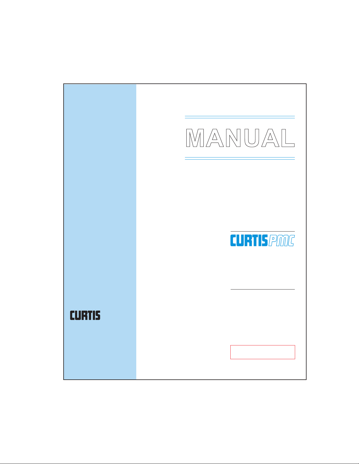
1
Fig. 1 Curtis PMC
1209B full-feature
electronic motor
controller.
Models 1221B, 1221C,
and 1231C have
similar external
connections.

Curtis PMC 1209B/1221B/1221C/1231C Manual
2
OVERVIEW
Working on electric vehicles is potentially dangerous. You should protect
yourself against runaways, high current arcs, and outgassing from lead acid
batteries:
RUNAWAYS — Some fault conditions could cause the vehicle to run out of
control. Jack up the vehicle and get the drive wheels off the ground before
attempting these procedures or any other work on the motor control
circuitry.
HIGH CURRENT ARCS — Electric vehicle batteries can supply very high power,
and arcs can occur if they are short circuited. Always open the battery circuit
before working on the motor control circuit. Wear safety glasses, and use
properly insulated tools to prevent shorts.
LEAD ACID BATTERIES — Charging or discharging generates hydrogen gas,
which can build up in and around the batteries. Follow the battery
manufacturer’s safety recommendations.
Wear safety glasses.
✓ Undervoltage cutback function protects against low battery voltage, includ-
ing low voltage caused by external loads
✓ Throttle pot fault circuitry shuts off the motor in the event of an open circuit
fault in the throttle or its wiring, to prevent runaway conditions
✓ Frequency shifting feature provides improved control of current limit at low
duty cycles [“C” models only]
✓ Simple installation with no adjustments required
✓ Tin-plated solid copper bus bars
✓ Push-on connectors for control wiring
Familiarity with your Curtis PMC controller will help you to install and operate
it properly. We encourage you to read this manual carefully. If you have
questions, please contact the Curtis office nearest you.
☞
C A U T I O N
Curtis PMC 1209B/1221B/1221C/1231C Manual
3
HARDWARE INSTALLATION
HARDWARE INSTALLATION
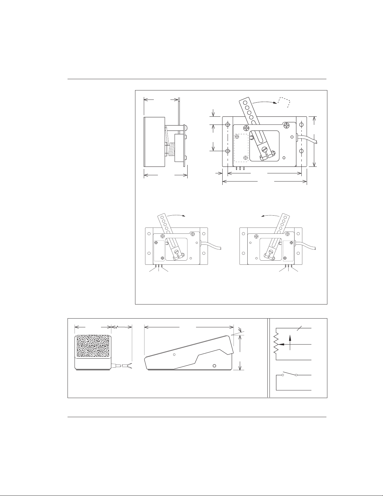
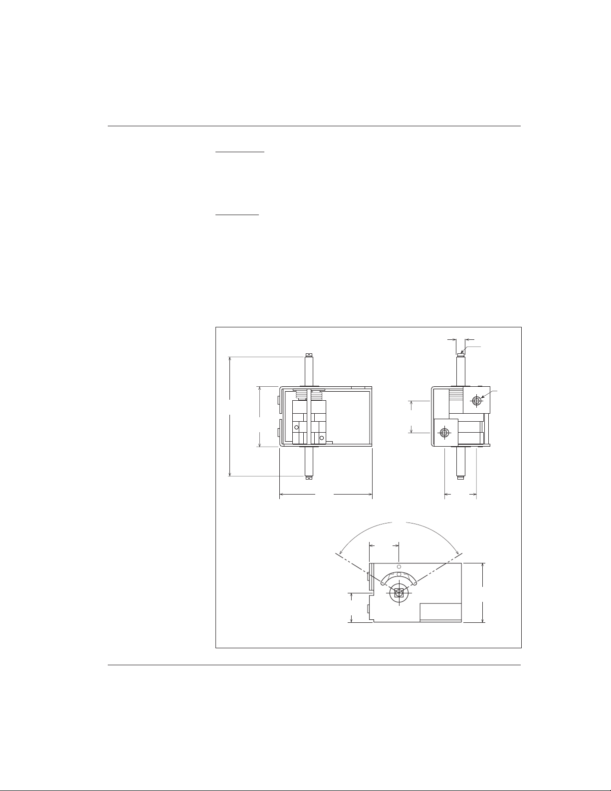
CONTROLLER
The controller can be oriented in any position, but the location should be
carefully chosen to keep the controller as clean and dry as possible. If a clean,
dry mounting location cannot be found, a cover must be used to deflect dirt
and water splash.
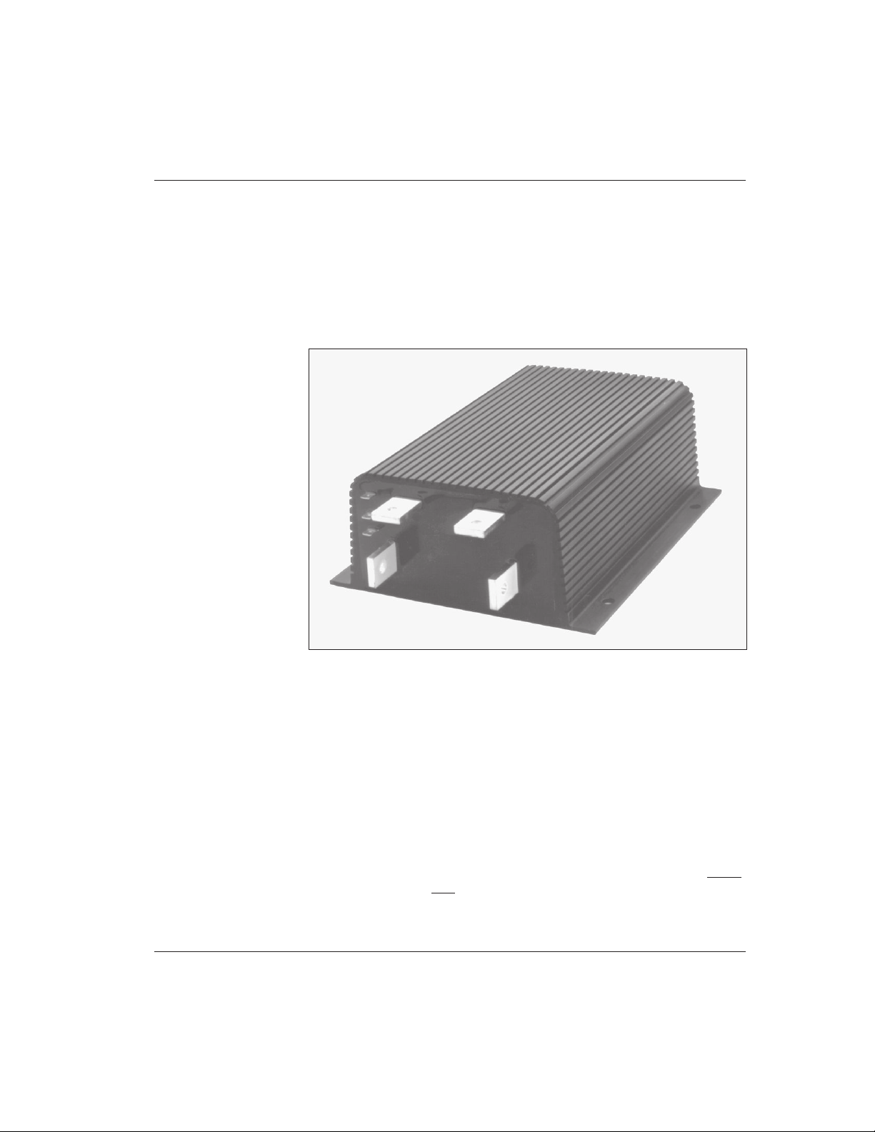
1209B, 1221B, and 1221C
The controller should be fastened with four screws to a clean, flat metal surface
that provides an adequate heat sink. The mounting surface is an integral part of
the overall heatsinking of the controller, and affects its ability to dissipate heat.
The case outline and mounting dimensions are shown in Figure 2.
2
Fig. 2 Mounting
dimensions, Curtis PMC
1209B/1221B/1221C
controllers.
6 (0.25)
male push-on,
2 plcs
7 (0.28) dia.
15 (0.60)
MODEL
1209:
231 (9.1)
MODEL
1221:
282 (11.1)
3.3
(0.13)
80 (3.15)
37 (1.45)
Dimensions in millimeters and (inches)
MODEL
1209:
152 (6.0)
MODEL
1221:
203 (8.0)
180 (7.1)
165 (6.5)
143 (5.6)
8.4 (0.33) dia.
25
×
19 × 5
(1.0
×
0.75 × 0.187)
Curtis PMC 1209B/1221B/1221C/1231C Manual
4
HARDWARE INSTALLATION
Fig. 3 Mounting
dimensions, Curtis PMC
1231C controller.
Be sure to mount the 1209B/1221B/1221C controller so as to allow access
to the adjustment screws. Although not usually necessary, a thermal joint
compound can be used to improve heat conduction from the case to the
mounting surface.
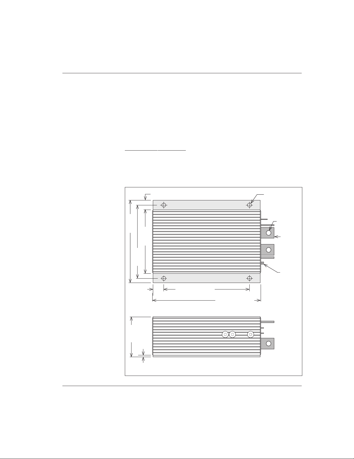
1231C
The controller should be fastened to a clean, flat metal surface that provides an
adequate heat sink. The mounting surface is an integral part of the overall
heatsinking of the controller, and affects its ability to dissipate heat.
B-
O P T I O N A L H E A T S I N K B A S E
B+
A2
M-
Dimensions in millimeters and (inches)
175 (6.9)
173 (6.8)
220 (8.6)
Mounting Clamp
(6 supplied)
94 (3.7)
Mounting
Clamp
(1/4-20 UNC),
6 places
(1/4-20 UNC)
×
8 (5/16),
6 places
229 (9.0)
114 (4.5)
165 (6.5)
32 (1.25)
200 (7.9)
140 (5.5)
Optional
Heatsink
Base
30 (1.2)
7 (9/32) dia.,
4 places
40
(1.6)

Curtis PMC 1209B/1221B/1221C/1231C Manual
5
HARDWARE INSTALLATION
Six mounting clamps are provided, which can be used to attach the control-
ler to its matching heatsink (Curtis PMC p/n 16421001) or to some other
surface. An alternative mounting method is provided by six tapped holes on the
bottom of the controller. The case outline, heatsink outline, and mounting
dimensions are shown in Figure 3.
Be sure to mount the 1231C controller so as to allow access to the adjust-
ment screws. Although not usually necessary, a thermal joint compound can be
used to improve heat conduction from the case to the mounting surface.
THROTTLE
0–5kΩ Input
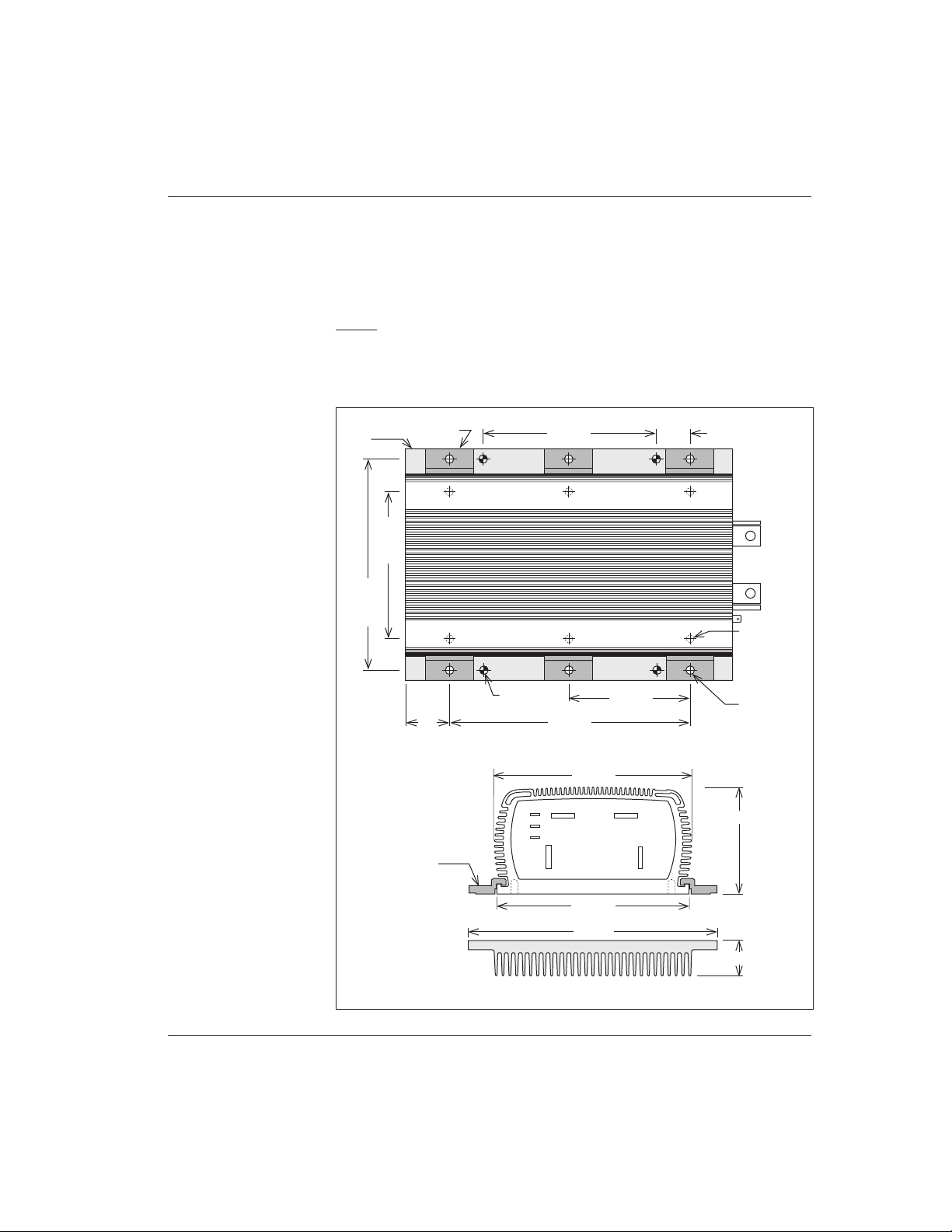
The standard controller throttle input is 0–5kΩ. Curtis PMC potboxes (PB-5,
-6, -9, -10) are designed to match this input. Some of these potboxes have a builtin microswitch, eliminating the need to install a separate pedal-actuated
microswitch. Curtis PMC also offers a self-contained footpedal unit (FP-2) that
eliminates the need for fabricating and installing a pedal-potbox linkage. Mounting dimensions for the potboxes and for the footpedal unit are shown in Figures
4 and 5.
Any potbox that provides a nominal 0–5kΩ output (controller output
begins at ≈300 ohms, full output is ≈4400 ohms) will work with the standard
throttle input. For other types, contact your Curtis office.
If a Curtis PMC potbox is used, it must be mounted so as to allow
connection between the potbox lever arm and the vehicle accelerator linkage.
The lever arm provides a series of holes so that the accelerator pedal “throw” can
be converted into the correct amount of potentiometer rotation. Use of a second
return spring on the pedal, in addition to the potbox return spring, is required to
prevent an uncontrollable full-on throttle input (which could happen if there was
a single spring, and it broke). If the self-contained potbox spring is insufficient to
return the pedal by itself, two additional pedal return springs must be used.
It is also required that the accelerator pedal hit a mechanical stop at its full-
on position just before (≈1 mm [1/32"–1/16"]) the potbox lever hits its own fullon stop. This mechanical stop will prevent the potbox lever arm from bending if
undue force is put on the pedal. Protection of the potbox from water and dirt will
help avoid problems of corrosion and electrical leakage.
After the potbox has been mounted, operation of the pot can be tested by
measuring the resistance between the two wires with an ohmmeter. With the
pedal not applied, the resistance should be less than 50 ohms. As the pedal is
applied, the resistance should rise smoothly until it reaches a value between 4500
and 5500 ohms. Values below 4500 ohms may cause a reduction in efficiency
and top speed. Values above 7000 ohms indicate a defective potbox, and will
cause controller shutdown.
Curtis PMC 1209B/1221B/1221C/1231C Manual
6
Fig. 4 Mounting
dimensions,
Curtis PMC potboxes
PB-5, -6, -9, and -10.
HARDWARE INSTALLATION
10 (0.38)
32
(1.25)
6
(0.25)
89 (3.5)
60
(2.37)
102 (4.0)
45
°
Dimensions in millimeters and (inches)
RIGHT-HAND OPERATION LEFT-HAND OPERATION
COM. N.O. N.C.
N.C. N.O. COM.
WITH MICROSWITCH: PB-6
WITHOUT MICROSWITCH: PB-5
WITH MICROSWITCH: PB-9
WITHOUT MICROSWITCH: PB-10
42 (1.65)
52 (2.06)
Fig. 5 Curtis PMC footpedal FP-2.
Dimensions in millimeters and (inches)
≈15°
244 (9.6)
112 (4.4)
112
(4.4)
1.8 m
(6 ft)
WIRING:
BLACK
= throttle input
BLUE
= switch, common (Note: The green wire is not used with
WHITE
= throttle input
ORANGE
= switch, normally open 1209B/1221B/1221C/1231C controllers)
BLK
ON
GRN
(not used)
WHT
ORG
BLU
COM.N.O.
Curtis PMC 1209B/1221B/1221C/1231C Manual
7
HARDWARE INSTALLATION
5kΩ–0 Input
The 1209B/1221B/1221C/1231C controllers are also available with 5kΩ–0
throttle inputs. Using this throttle type, controller output begins at ≈4400 ohms
with full output at less than 300 ohms.
0–5V Input
A 0–5V throttle input option is also available for these controllers. The negative
side of the 5V source should be referenced to B- and must be capable of driving
an input impedance of 5kΩ.
Curtis offers two bi-directional, wigwag electronic throttle assemblies designed for use with the 0–5V input: the ET series and the CH series. They
require a 24–36V supply voltage.
The ET-XXX throttle assembly provides a 0–5V output and forward/reverse
relay coil drivers. Dimensions for the ET-series throttles are shown in Figure 6.
Dimensions in millimeters and (inches)
99
(3.90)
44
(1.73)
69
(2.72)
24
(0.94)
VIS TC 3×12
6 × 6 (0.24 × 0.24)
24
(0.94)
∅ M5
22
(0.87)
22
(0.87)
116
°
44
(1.73)
Fig. 6 Mounting
dimensions,
Curtis electronic throttle
(ET series).
Curtis PMC 1209B/1221B/1221C/1231C Manual
8
HARDWARE INSTALLATION
Fig. 7 Typical installation, Curtis PMC 1209B/1221B/1221C controllers.
The CH-XXX is a complete control head assembly, consisting of an ET-XXX
throttle integrated into a molded steel and plastic assembly designed for mounting directly to the tiller stem of material handling lifts. For more information
about ET and CH products, call your local dealer or Curtis office.
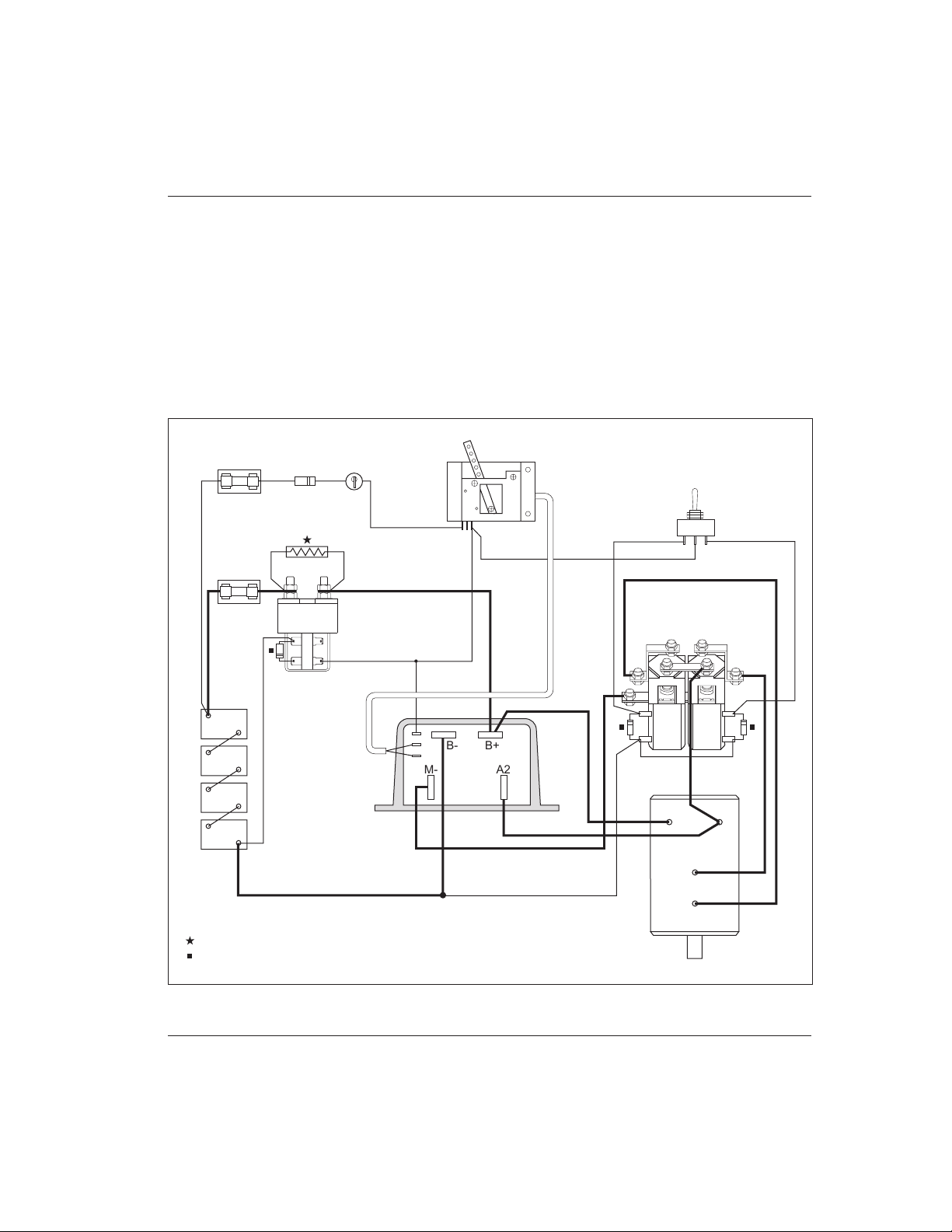
OTHER HARDWARE
The recommended hardware for a typical 1209B, 1221B, or 1221C controller
installation is shown in Figure 7, and for a 1231C installation in Figure 8.
CONTROL
WIRING
FUSE
POWER
WIRING
FUSE
POLARITY
PROTECTION
DIODE
KEYSWITCH
POTBOX
FORWARD/REVERSE SWITCH
(SPDT, center off)
F R
FORWARD/REVERSE
CHANGEOVER CONTACTOR
(Albright SW202 shown)
MAIN
CONTACTOR
(Albright SW200
shown)
A1
A2
S1
S2
SERIES
MOTOR
BATTERY
B-
B+
PRECH ARGE RE SISTOR (see Table 1 , page 1 0, for re commen ded siz e)
COIL S UPPRES SION DI ODE (se e text, page 10 , for rec ommend ed size )
FWD REV
A2M-
B-
B+
COM.
N.C.
Curtis PMC 1209B/1221B/1221C/1231C Manual
9
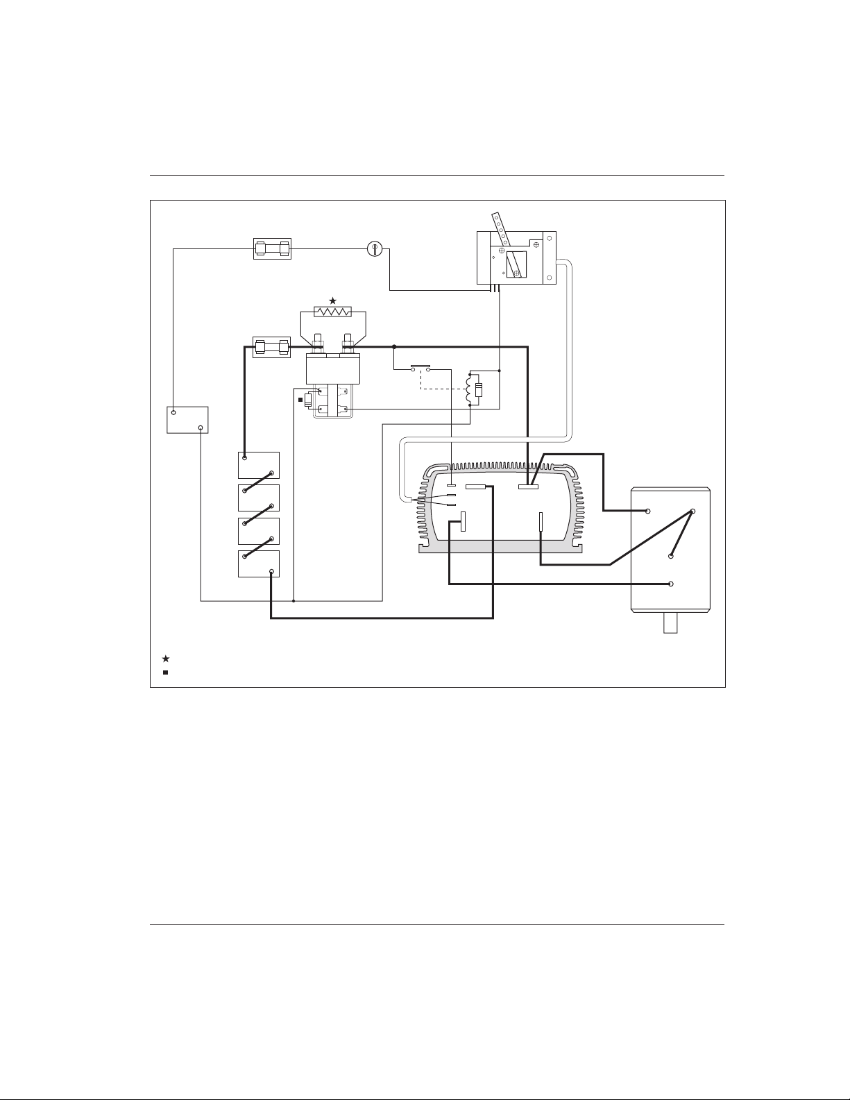
Fig. 8 Typical installation, Curtis PMC 1231C controller.
Contactors should be mounted in a clean, dry location. If such a location is
unavailable, a cover should be used to deflect dirt and water splash.
The precharge resistor and coil suppression diode connected to the main
contactor (and the coil suppression diodes connected to the forward/reverse
contactors in “B” applications) are somewhat delicate components. Care should
be taken to prevent damaging them during installation.
HARDWARE INSTALLATION
CONTROL
WIRING
FUSE
POWER
WIRING
FUSE
KEYSWITCH
POTBOX
MAIN
CONTACTOR
(Albright SW200
shown)
TRACTION BATTERY
B-
B+
PRECH ARGE RE SISTOR (see Table 1 , page 1 0, for re commen ded siz e)
COIL S UPPRES SION DI ODE (se e text, page 10 , for rec ommend ed size )
A1
A2
S1
S2
SERIES
MOTOR
12V
AUXILIARY
BATTERY
B+
B-
KSI RELAY
B- B+
A2
M-
COM.
N.C.

Curtis PMC 1209B/1221B/1221C/1231C Manual
10
HARDWARE INSTALLATION
Main Contactor
Most applications use a main contactor in series with the battery positive (B+)
cable to disconnect all power when the system is turned off, as shown in Figures
7 and 8. A heavy-duty single-pole, single-throw (SPST) contactor with silveralloy contacts is recommended, such as an Albright SW200 (available from
Curtis).
A coil suppression diode should be used on the contactor coil. Curtis PMC
p/n MP-1 (which is rated at 100 volts, 3 amps) is appropriate in systems up to
72V. In systems with nominal voltage greater than 72V where the contactor coils
are energized from the battery pack, a diode with a breakdown voltage of at least
200 volts should be used.
The rapid charging of the controller’s internal filter capacitors causes a high
inrush current to flow briefly when the contactor closes. To extend contact life,
a precharge resistor is recommended; the resistor precharges the capacitors and
reduces the inrush current through the contacts. If an inexpensive “can” type
solenoid is used, the resistor is mandatory to prevent contact welding.
The recommended precharge resistance values and power ratings are listed
in Table 1. These resistors will provide the maximum precharge voltage while
being capable of dissipating the power generated by the full battery voltage
without failure. NOTE: A resistor with a lower power rating may catch on fire if a
system fault applies the full battery voltage across it.
Table 1 RECOMMENDED PRECHARGE RESISTORS
CONTROLLER RESISTANCE POWER RATING
MODEL NUMBER (Ω) (W)
1209B -46XX 270 5
-55XX 270 10
-64XX 620 10
-6A5XX 620 10
-72XX 750 20
1221B -48XX 270 5
-57XX 270 10
-66XX 620 10
-6A7XX 620 10
1221C -74XX 750 20
1231C -77XX 750 20
-86XX 750 25
 Loading...