

1209B/1221B
1221C/1231C
© 1999 CURTIS INSTRUMENTS, INC.
DESIGN OF CURTIS PMC 1200 SERIES
CONTROLLERS PROTECTED BY U.S.
PATENT NO. 4626750.
MOTOR CONTROLLERS
1209B/1221B/1221C/1231C Manual
p/n 98827, Rev. D: August 1999
MANUAL
CURTIS PMC
235 East Airway Boulevard
Livermore, California 94568 USA
Tel: 925-961-1088
Fax: 925-961-1099
www.curtisinst.com

1209B / 1221B / 1221C / 1231C Manual
p/n 98827, Rev. D: August 1999
© 1999 CURTIS INSTRUMENTS, INC.
This electronic version of the 1209B/1221B/1221C/1231C manual is offered as a
convenience to our customers. You may download any or all of it.
If you would like a hard copy of the published manual, please order it by part number from
the Curtis office nearest you.
The electronic version of the manual is identical to the printed version published in August
1999. Bookmarks have been added to the electronic version to speed the process of going
directly to a particular part of the document.
CURTIS INSTRUMENTS, INC.
200 KISCO AVENUE
MOUNT KISCO, NEW YORK 10549 USA
☎
914-666-2971 FAX 914-666-2188
■ CURTIS PMC
235 EAST AIRWAY BOULEVARD
LIVERMORE, CALIFORNIA 94550 USA
☎
925-961-1088 FAX 925-961-1099
■
ADDITIONAL OFFICES located in
Bulgaria, China, England, France, Germany,
India, Italy, Japan, Netherlands, Puerto Rico,
Russia, Sweden, and Switzerland
Curtis PMC 1209B/1221B/1221C/1231C Manual iii
234567890
1
234567890
1
234567890
1
234567890
1
234567890
1
234567890
1
234567890
1
234567890
1
234567890
1
234567890
1
234567890
1
234567890
1
234567890
1
234567890
1
234567890
1
234567890
1
234567890
1
234567890
1
234567890
1
234567890
1
234567890
1
234567890
1
234567890
1
234567890
1
234567890
1
234567890
1
234567890
1
234567890
1
234567890
1
234567890
1
234567890
1
234567890
1
234567890
1
234567890
1
234567890
1
234567890
1
234567890
1
234567890
1
234567890
1
234567890
1
234567890
1
234567890
1
234567890
1
234567890
1
234567890
1
234567890
1
234567890
1
234567890
1
234567890
1
234567890
1
234567890
1
234567890
1
234567890
1
234567890
1
234567890
1
234567890
1
234567890
1
234567890
1
234567890
1
234567890
1
234567890
1
234567890
1
234567890
1
234567890
1
234567890
1
234567890
1
234567890
1
234567890
1
234567890
1
234567890
1
234567890
1
234567890
1
234567890
1
234567890
1
234567890
1
234567890
1
234567890
1
234567890
1
234567890
1
234567890
1
234567890
1
234567890
1
234567890
1
234567890
1
234567890
1
234567890
1
234567890
1
234567890
1
234567890
1
234567890
1
234567890
1
234567890
1
234567890
1
234567890
1
234567890
1
234567890
1
234567890
1
234567890
1
234567890
1
234567890
1
234567890
1
234567890
1
234567890
1
234567890
1
234567890
1
234567890
1
234567890
1
234567890
1
234567890
1
234567890
1
234567890
1
234567890
1
234567890
1
234567890
1
CONTENTS
1. OVERVIEW .......................................................................1
2. HARDWARE INSTALLATION ....................................... 3
Controller .................................................................... 3
Throttle ........................................................................ 5
Other Hardware ...........................................................8
Main contactor ................................................... 10
Forward/reverse contactors .................................. 11
Forward/reverse switches ..................................... 11
Keyswitch and interlocks .....................................11
Keyswitch relay ................................................... 11
Polarity protection diode ..................................... 12
Control wiring fuse ............................................. 12
Power wiring fuse ................................................ 12
3. WIRING ........................................................................... 13
Connections: Low Current ......................................... 13
Connections: High Current ....................................... 13
Wiring: Typical Installation ....................................... 14
KSI wiring .......................................................... 15
Forward/reverse wiring ........................................ 16
Plug braking ................................................ 16
Freewheeling ................................................16
Throttle wiring ................................................... 17
Standard potbox wiring ...............................17
Pots for twist-grip throttles .......................... 18
Electronic throttle wiring ............................. 19
Reduced speed operation ............................. 20
Throttle ramp shaping ................................. 21
Installation Checkout ................................................. 22
CONTENTS
Curtis PMC 1209B/1221B/1221C/1231C Manual iv
CONTENTS
23456789
0
23456789
0
23456789
0
23456789
0
23456789
0
23456789
0
23456789
0
23456789
0
23456789
0
23456789
0
23456789
0
23456789
0
23456789
0
23456789
0
23456789
0
23456789
0
23456789
0
23456789
0
23456789
0
23456789
0
23456789
0
23456789
0
23456789
0
23456789
0
23456789
0
23456789
0
23456789
0
23456789
0
23456789
0
23456789
0
23456789
0
23456789
0
23456789
0
23456789
0
23456789
0
23456789
0
23456789
0
23456789
0
23456789
0
23456789
0
23456789
0
23456789
0
23456789
0
23456789
0
23456789
0
23456789
0
23456789
0
23456789
0
23456789
0
23456789
0
23456789
0
23456789
0
23456789
0
23456789
0
23456789
0
4. MAINTENANCE AND ADJUSTMENT ....................... 24
Controller .................................................................. 24
Potbox ........................................................................ 25
5. TROUBLESHOOTING AND BENCH TESTING ....... 27
Operational Notes ......................................................27
In-Vehicle Diagnostic Tests (Troubleshooting) .......... 28
Bench Testing ............................................................ 34
6. GLOSSARY: FEATURES AND FUNCTIONS .............. 37
APPENDIX A Functional Description ................................ A-1
APPENDIX B Pulse Width Modulation ............................. B-1
APPENDIX C Electrical Specifications ................................ C-1

Curtis PMC 1209B/1221B/1221C/1231C Manual v
FIGURES
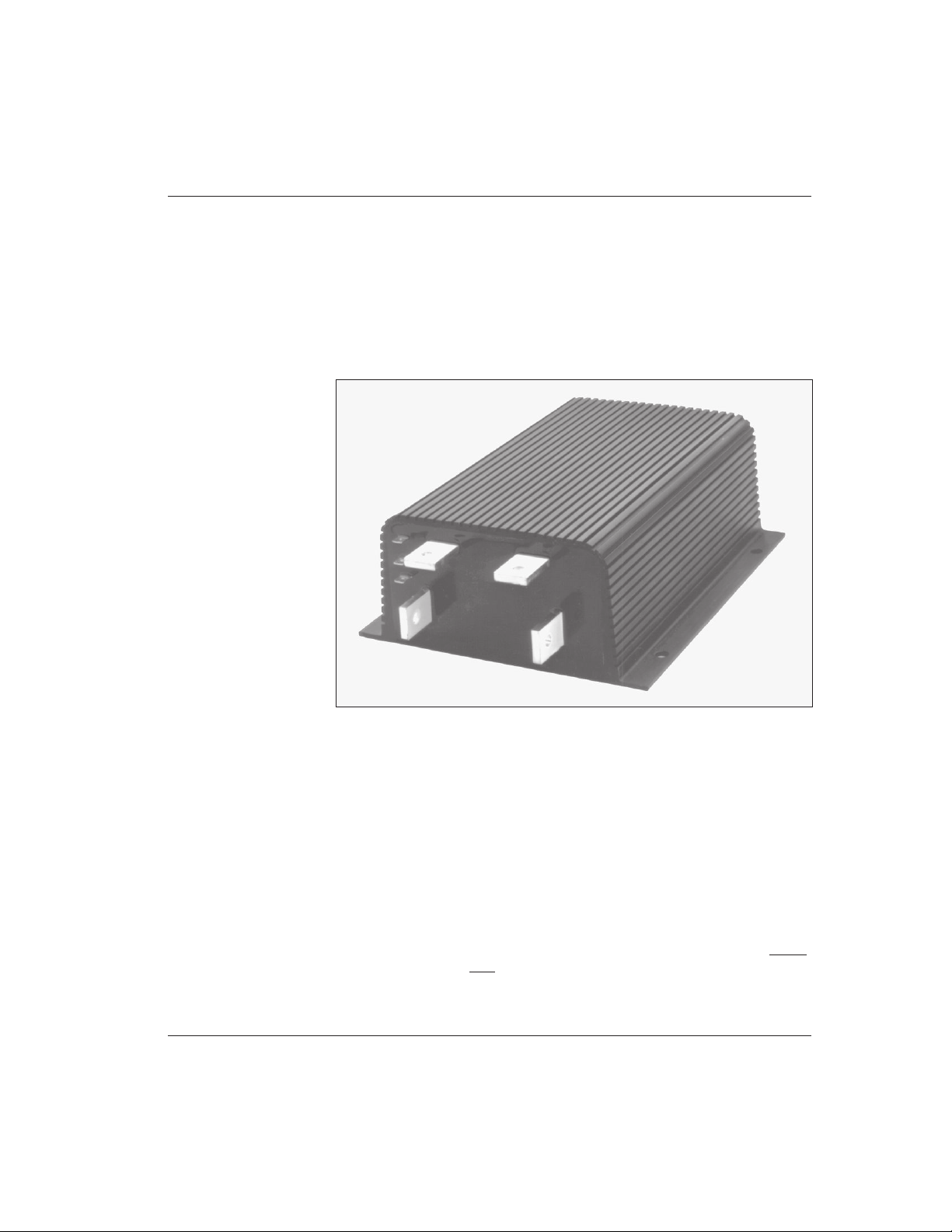
FIG. 1: Curtis PMC 1209B full-feature
motor controller ......................................................... 1
FIG. 2: Mounting dimensions,
Curtis PMC 1209B/1221B/1221C controllers ........... 3
FIG. 3: Mounting dimensions,
Curtis PMC 1231C controller ................................... 4
FIG. 4: Mounting dimensions,
Curtis PMC potboxes PB-5, -6, -9, and -10 ............... 6
FIG. 5: Mounting dimensions, Curtis PMC footpedal ........... 6
FIG. 6: Mounting dimensions,
Curtis electronic throttle (ET series) ........................... 7
FIG. 7: Typical installation,
1209B/1221B/1221C controllers ............................... 8
FIG. 8: Typical installation, 1231C controller ........................9
FIG. 9: Basic wiring configuration,
1209B/1221B/1221C controllers ............................. 14
FIG. 10: Basic wiring configuration, 1231C controller ........... 15
FIG. 11: Control wiring for inhibiting plug braking,
in order to allow freewheeling .................................. 17
FIG. 12: Standard throttle pot, 0–5kΩ ................................... 17
FIG. 13: Bi-directional twist-grip throttle with
a standard 20 kΩ pot and a controller
with the optional 5kΩ–0 throttle input .................... 18
FIGURES

Curtis PMC 1209B/1221B/1221C/1231C Manual vi
FIGURES/TABLES
FIG. 14: Curtis electronic throttle (ET series)
with a controller having the optional
0–5V throttle input .................................................. 19
FIG. 15: Reduced speed operation (with standard
(0–5kΩ pot) ............................................................. 20
FIG. 16: Throttle ramp shapes ................................................21
FIG. 17: Adjustment pots ....................................................... 25
FIG. 18: Guide to troubleshooting procedures ....................... 29
FIG. 19: Setup for bench testing ............................................. 35
FIG. A-1: Block diagram, Curtis PMC
1209B/1221B/1221C/1231C controllers ............... A-1
FIG. B-1: Pulse width modulation.......................................... B-1
TABLES
TABLE 1: Recommended precharge resistors ......................... 10
TABLE C-1: Electrical specifications, 1209B/1221B ............... C-1
TABLE C-2: Electrical specifications, 1221C/1231C ............... C-2
Curtis PMC 1209B/1221B/1221C/1231C Manual
1
OVERVIEW
OVERVIEW
Curtis PMC Model 1209B/1221B and 1221C/1231C electronic motor speed
controllers are designed to provide smooth, silent, cost-effective control of motor
speed and torque on a wide variety of electric vehicles. The 1209B/1221B
controllers are designed primarily for material handling applications, and the
1221C/1231C controllers for on-road vehicles.
Like all Curtis PMC 1200 series controllers, the 1209B/1221B/1221C/1231C
models offer superior operator control of the vehicle’s motor drive speed. Key
features of these controllers include:
✓ Infinitely variable drive and brake control
✓ Power MOSFET design provides high efficiency (for reduced motor and
battery losses) and silent operation
✓ High pedal disable (HPD) function monitors throttle status during turn-on
and prevents operation until throttle has been returned to neutral [optional
feature]
✓ Thermal protection and compensation circuit provides both
undertemperature and overtemperature cutback, as well as steady current limit
throughout the entire operating range
More Features
☞
1
Fig. 1 Curtis PMC
1209B full-feature
electronic motor
controller.
Models 1221B, 1221C,
and 1231C have
similar external
connections.

Curtis PMC 1209B/1221B/1221C/1231C Manual
2
OVERVIEW
Working on electric vehicles is potentially dangerous. You should protect
yourself against runaways, high current arcs, and outgassing from lead acid
batteries:
RUNAWAYS — Some fault conditions could cause the vehicle to run out of
control. Jack up the vehicle and get the drive wheels off the ground before
attempting these procedures or any other work on the motor control
circuitry.
HIGH CURRENT ARCS — Electric vehicle batteries can supply very high power,
and arcs can occur if they are short circuited. Always open the battery circuit
before working on the motor control circuit. Wear safety glasses, and use
properly insulated tools to prevent shorts.
LEAD ACID BATTERIES — Charging or discharging generates hydrogen gas,
which can build up in and around the batteries. Follow the battery
manufacturer’s safety recommendations.
Wear safety glasses.
✓ Undervoltage cutback function protects against low battery voltage, includ-
ing low voltage caused by external loads
✓ Throttle pot fault circuitry shuts off the motor in the event of an open circuit
fault in the throttle or its wiring, to prevent runaway conditions
✓ Frequency shifting feature provides improved control of current limit at low
duty cycles [“C” models only]
✓ Simple installation with no adjustments required
✓ Tin-plated solid copper bus bars
✓ Push-on connectors for control wiring
Familiarity with your Curtis PMC controller will help you to install and operate
it properly. We encourage you to read this manual carefully. If you have
questions, please contact the Curtis office nearest you.
☞
C A U T I O N
Curtis PMC 1209B/1221B/1221C/1231C Manual
3
HARDWARE INSTALLATION
HARDWARE INSTALLATION
CONTROLLER
The controller can be oriented in any position, but the location should be
carefully chosen to keep the controller as clean and dry as possible. If a clean,
dry mounting location cannot be found, a cover must be used to deflect dirt
and water splash.
1209B, 1221B, and 1221C
The controller should be fastened with four screws to a clean, flat metal surface
that provides an adequate heat sink. The mounting surface is an integral part of
the overall heatsinking of the controller, and affects its ability to dissipate heat.
The case outline and mounting dimensions are shown in Figure 2.
2
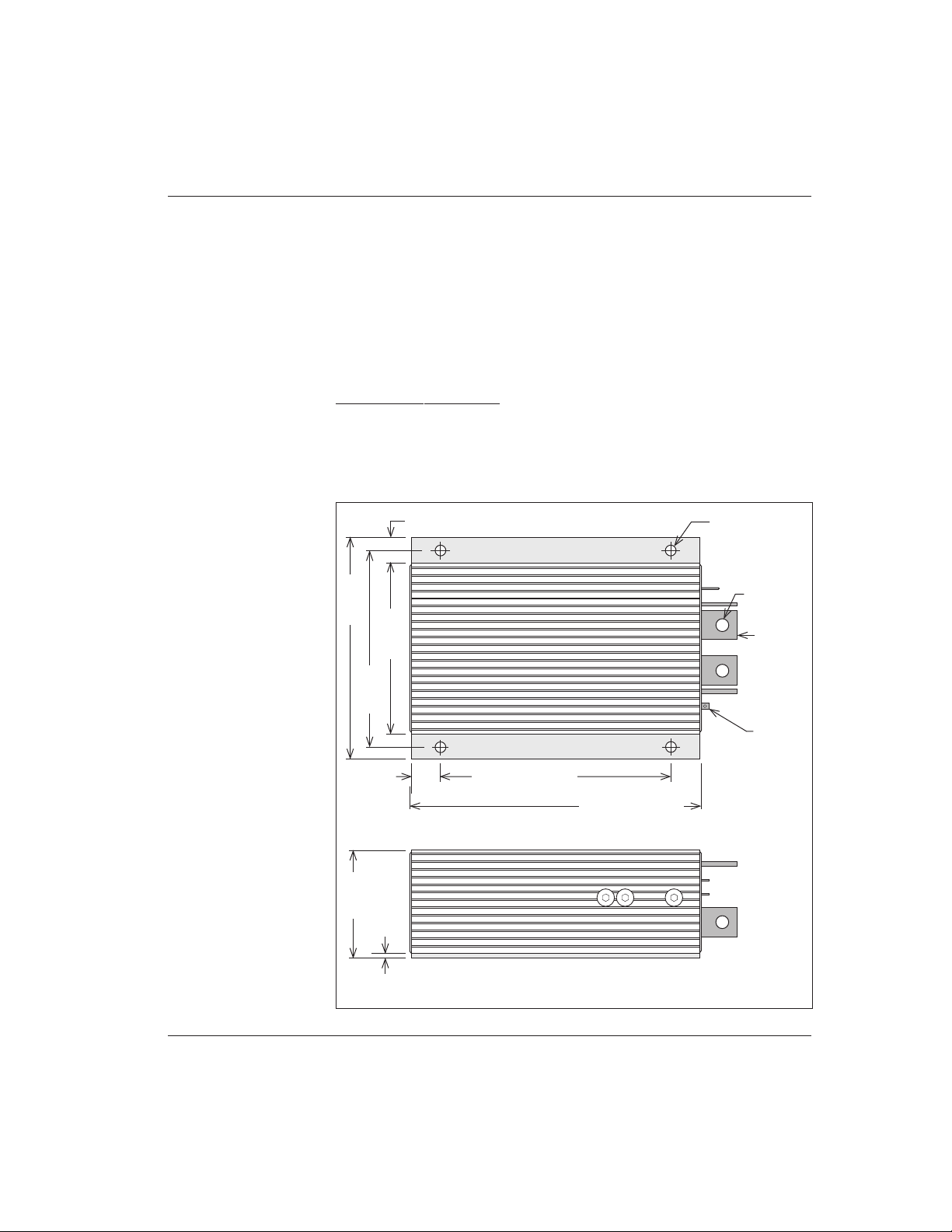
Fig. 2 Mounting
dimensions, Curtis PMC
1209B/1221B/1221C
controllers.
6 (0.25)
male push-on,
2 plcs
7 (0.28) dia.
15 (0.60)
MODEL
1209:
231 (9.1)
MODEL
1221:
282 (11.1)
3.3
(0.13)
80 (3.15)
37 (1.45)
Dimensions in millimeters and (inches)
MODEL
1209:
152 (6.0)
MODEL
1221:
203 (8.0)
180 (7.1)
165 (6.5)
143 (5.6)
8.4 (0.33) dia.
25
×
19 × 5
(1.0
×
0.75 × 0.187)
Curtis PMC 1209B/1221B/1221C/1231C Manual
4
HARDWARE INSTALLATION
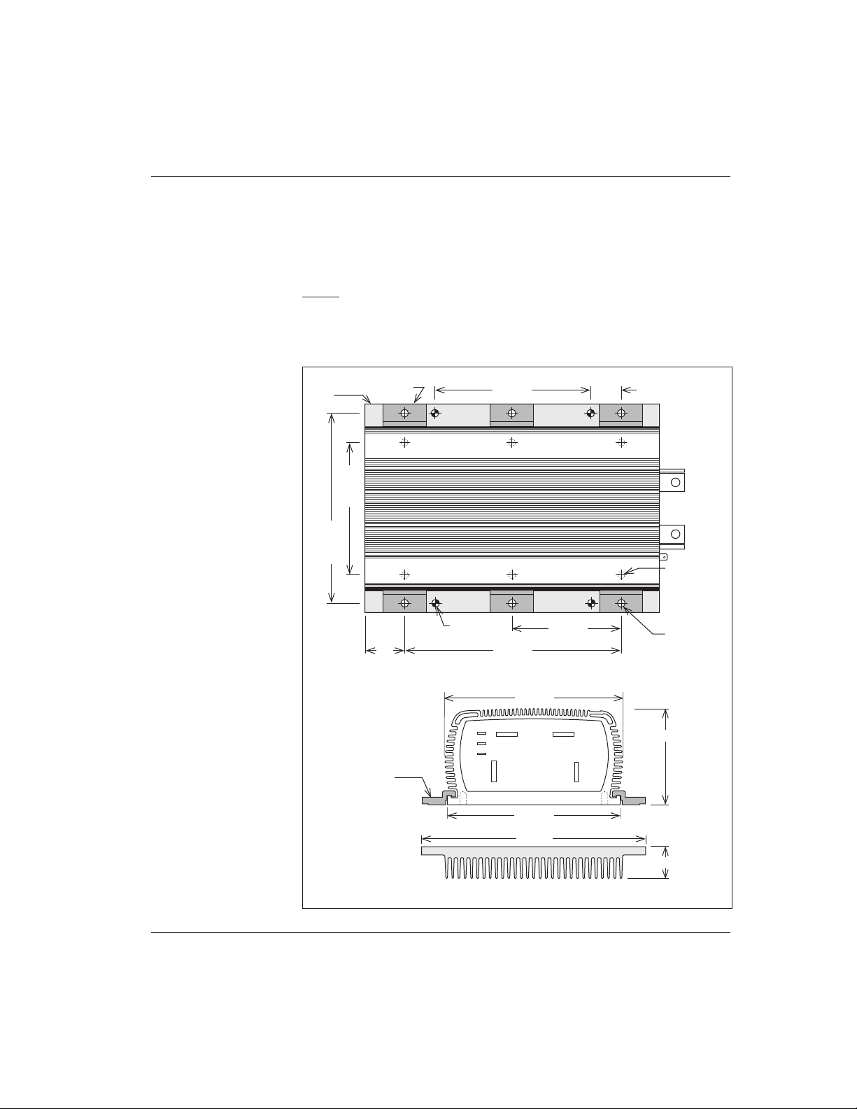
Fig. 3 Mounting
dimensions, Curtis PMC
1231C controller.
Be sure to mount the 1209B/1221B/1221C controller so as to allow access
to the adjustment screws. Although not usually necessary, a thermal joint
compound can be used to improve heat conduction from the case to the
mounting surface.
1231C
The controller should be fastened to a clean, flat metal surface that provides an
adequate heat sink. The mounting surface is an integral part of the overall
heatsinking of the controller, and affects its ability to dissipate heat.
B-
O P T I O N A L H E A T S I N K B A S E
B+
A2
M-
Dimensions in millimeters and (inches)
175 (6.9)
173 (6.8)
220 (8.6)
Mounting Clamp
(6 supplied)
94 (3.7)
Mounting
Clamp
(1/4-20 UNC),
6 places
(1/4-20 UNC)
×
8 (5/16),
6 places
229 (9.0)
114 (4.5)
165 (6.5)
32 (1.25)
200 (7.9)
140 (5.5)
Optional
Heatsink
Base
30 (1.2)
7 (9/32) dia.,
4 places
40
(1.6)

Curtis PMC 1209B/1221B/1221C/1231C Manual
5
HARDWARE INSTALLATION
Six mounting clamps are provided, which can be used to attach the control-
ler to its matching heatsink (Curtis PMC p/n 16421001) or to some other
surface. An alternative mounting method is provided by six tapped holes on the
bottom of the controller. The case outline, heatsink outline, and mounting
dimensions are shown in Figure 3.
Be sure to mount the 1231C controller so as to allow access to the adjust-
ment screws. Although not usually necessary, a thermal joint compound can be
used to improve heat conduction from the case to the mounting surface.
THROTTLE
0–5kΩ Input
The standard controller throttle input is 0–5kΩ. Curtis PMC potboxes (PB-5,
-6, -9, -10) are designed to match this input. Some of these potboxes have a builtin microswitch, eliminating the need to install a separate pedal-actuated
microswitch. Curtis PMC also offers a self-contained footpedal unit (FP-2) that
eliminates the need for fabricating and installing a pedal-potbox linkage. Mounting dimensions for the potboxes and for the footpedal unit are shown in Figures
4 and 5.
Any potbox that provides a nominal 0–5kΩ output (controller output
begins at ≈300 ohms, full output is ≈4400 ohms) will work with the standard
throttle input. For other types, contact your Curtis office.
If a Curtis PMC potbox is used, it must be mounted so as to allow
connection between the potbox lever arm and the vehicle accelerator linkage.
The lever arm provides a series of holes so that the accelerator pedal “throw” can
be converted into the correct amount of potentiometer rotation. Use of a second
return spring on the pedal, in addition to the potbox return spring, is required to
prevent an uncontrollable full-on throttle input (which could happen if there was
a single spring, and it broke). If the self-contained potbox spring is insufficient to
return the pedal by itself, two additional pedal return springs must be used.
It is also required that the accelerator pedal hit a mechanical stop at its full-
on position just before (≈1 mm [1/32"–1/16"]) the potbox lever hits its own fullon stop. This mechanical stop will prevent the potbox lever arm from bending if
undue force is put on the pedal. Protection of the potbox from water and dirt will
help avoid problems of corrosion and electrical leakage.
After the potbox has been mounted, operation of the pot can be tested by
measuring the resistance between the two wires with an ohmmeter. With the
pedal not applied, the resistance should be less than 50 ohms. As the pedal is
applied, the resistance should rise smoothly until it reaches a value between 4500
and 5500 ohms. Values below 4500 ohms may cause a reduction in efficiency
and top speed. Values above 7000 ohms indicate a defective potbox, and will
cause controller shutdown.
Curtis PMC 1209B/1221B/1221C/1231C Manual
6
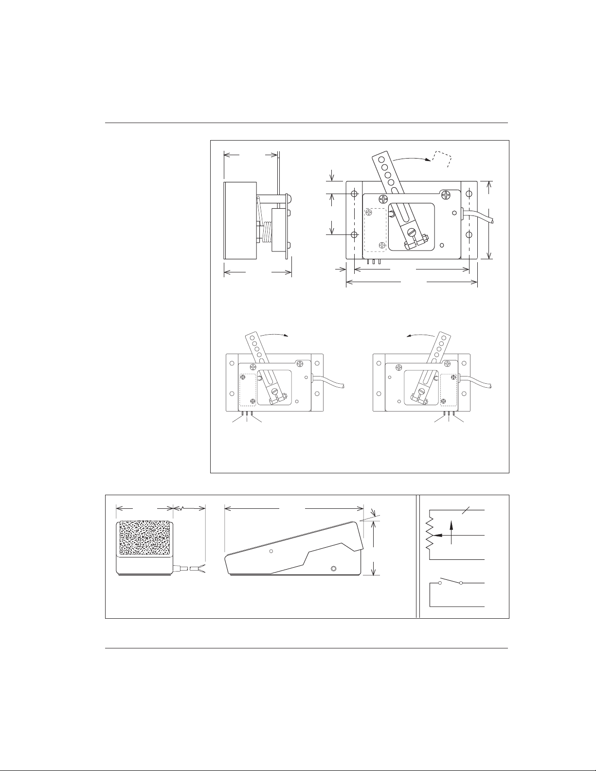
Fig. 4 Mounting
dimensions,
Curtis PMC potboxes
PB-5, -6, -9, and -10.
HARDWARE INSTALLATION
10 (0.38)
32
(1.25)
6
(0.25)
89 (3.5)
60
(2.37)
102 (4.0)
45
°
Dimensions in millimeters and (inches)
RIGHT-HAND OPERATION LEFT-HAND OPERATION
COM. N.O. N.C.
N.C. N.O. COM.
WITH MICROSWITCH: PB-6
WITHOUT MICROSWITCH: PB-5
WITH MICROSWITCH: PB-9
WITHOUT MICROSWITCH: PB-10
42 (1.65)
52 (2.06)
Fig. 5 Curtis PMC footpedal FP-2.
Dimensions in millimeters and (inches)
≈15°
244 (9.6)
112 (4.4)
112
(4.4)
1.8 m
(6 ft)
WIRING:
BLACK
= throttle input
BLUE
= switch, common (Note: The green wire is not used with
WHITE
= throttle input
ORANGE
= switch, normally open 1209B/1221B/1221C/1231C controllers)
BLK
ON
GRN
(not used)
WHT
ORG
BLU
COM.N.O.
Curtis PMC 1209B/1221B/1221C/1231C Manual
7
HARDWARE INSTALLATION
5kΩ–0 Input
The 1209B/1221B/1221C/1231C controllers are also available with 5kΩ–0
throttle inputs. Using this throttle type, controller output begins at ≈4400 ohms
with full output at less than 300 ohms.
0–5V Input
A 0–5V throttle input option is also available for these controllers. The negative
side of the 5V source should be referenced to B- and must be capable of driving
an input impedance of 5kΩ.
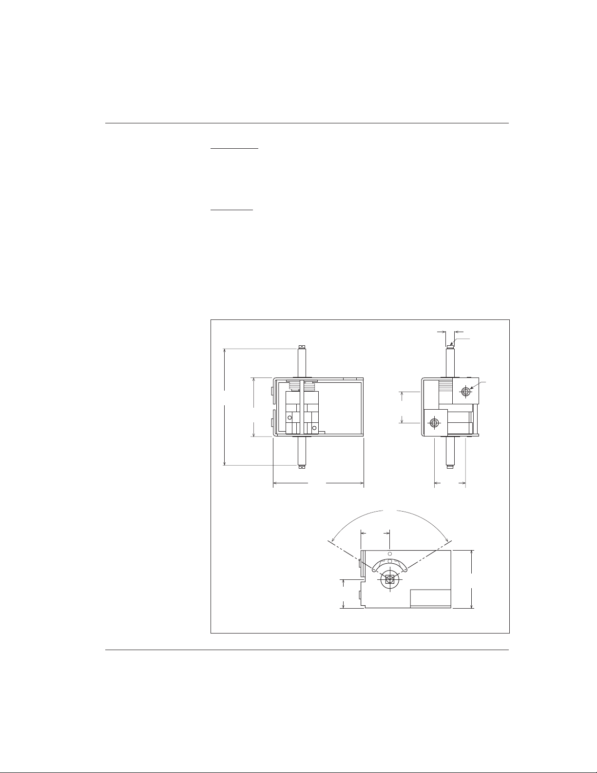
Curtis offers two bi-directional, wigwag electronic throttle assemblies designed for use with the 0–5V input: the ET series and the CH series. They
require a 24–36V supply voltage.
The ET-XXX throttle assembly provides a 0–5V output and forward/reverse
relay coil drivers. Dimensions for the ET-series throttles are shown in Figure 6.
Dimensions in millimeters and (inches)
99
(3.90)
44
(1.73)
69
(2.72)
24
(0.94)
VIS TC 3×12
6 × 6 (0.24 × 0.24)
24
(0.94)
∅ M5
22
(0.87)
22
(0.87)
116
°
44
(1.73)
Fig. 6 Mounting
dimensions,
Curtis electronic throttle
(ET series).
Curtis PMC 1209B/1221B/1221C/1231C Manual
8
HARDWARE INSTALLATION
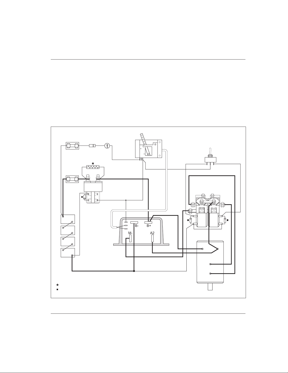
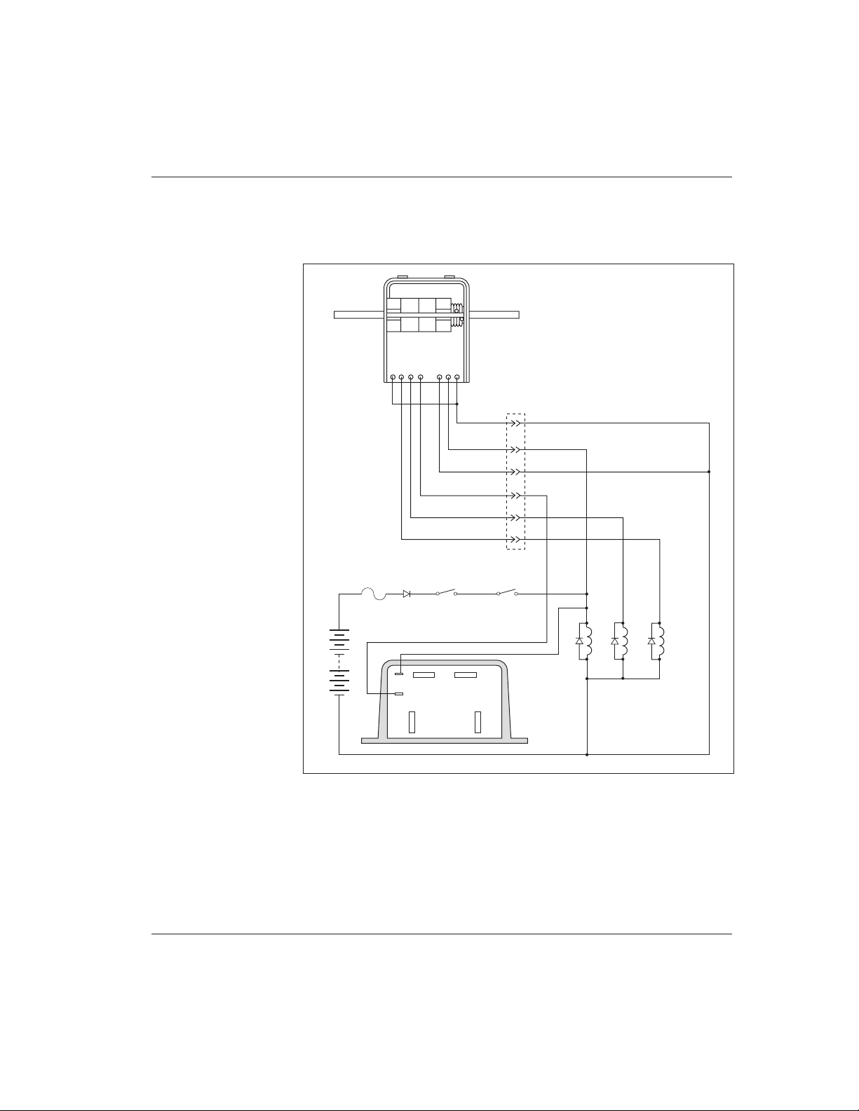
Fig. 7 Typical installation, Curtis PMC 1209B/1221B/1221C controllers.
The CH-XXX is a complete control head assembly, consisting of an ET-XXX
throttle integrated into a molded steel and plastic assembly designed for mounting directly to the tiller stem of material handling lifts. For more information
about ET and CH products, call your local dealer or Curtis office.
OTHER HARDWARE
The recommended hardware for a typical 1209B, 1221B, or 1221C controller
installation is shown in Figure 7, and for a 1231C installation in Figure 8.
CONTROL
WIRING
FUSE
POWER
WIRING
FUSE
POLARITY
PROTECTION
DIODE
KEYSWITCH
POTBOX
FORWARD/REVERSE SWITCH
(SPDT, center off)
F R
FORWARD/REVERSE
CHANGEOVER CONTACTOR
(Albright SW202 shown)
MAIN
CONTACTOR
(Albright SW200
shown)
A1
A2
S1
S2
SERIES
MOTOR
BATTERY
B-
B+
PRECH ARGE RE SISTOR (see Table 1 , page 1 0, for re commen ded siz e)
COIL S UPPRES SION DI ODE (se e text, page 10 , for rec ommend ed size )
FWD REV
A2M-
B-
B+
COM.
N.C.
Curtis PMC 1209B/1221B/1221C/1231C Manual
9
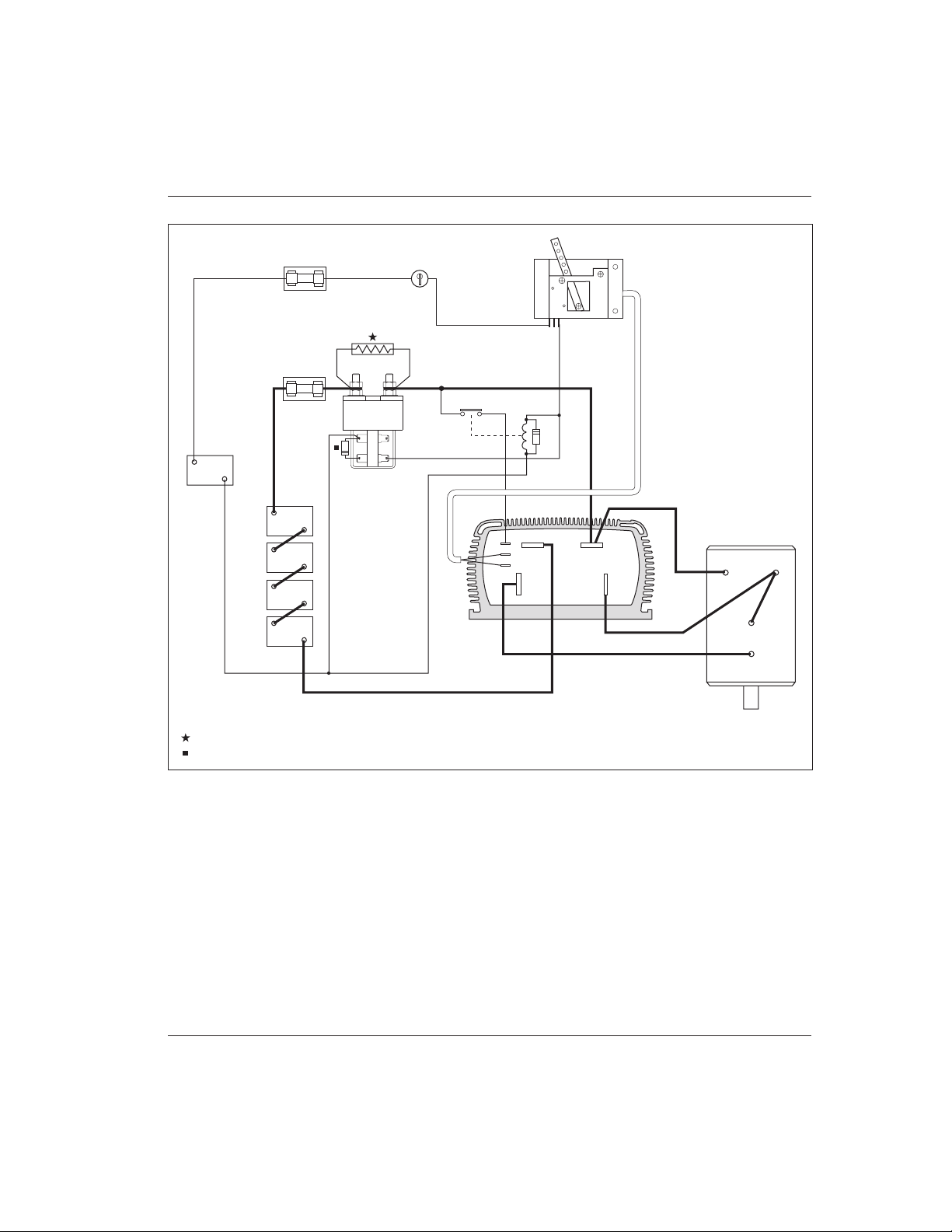
Fig. 8 Typical installation, Curtis PMC 1231C controller.
Contactors should be mounted in a clean, dry location. If such a location is
unavailable, a cover should be used to deflect dirt and water splash.
The precharge resistor and coil suppression diode connected to the main
contactor (and the coil suppression diodes connected to the forward/reverse
contactors in “B” applications) are somewhat delicate components. Care should
be taken to prevent damaging them during installation.
HARDWARE INSTALLATION
CONTROL
WIRING
FUSE
POWER
WIRING
FUSE
KEYSWITCH
POTBOX
MAIN
CONTACTOR
(Albright SW200
shown)
TRACTION BATTERY
B-
B+
PRECH ARGE RE SISTOR (see Table 1 , page 1 0, for re commen ded siz e)
COIL S UPPRES SION DI ODE (se e text, page 10 , for rec ommend ed size )
A1
A2
S1
S2
SERIES
MOTOR
12V
AUXILIARY
BATTERY
B+
B-
KSI RELAY
B- B+
A2
M-
COM.
N.C.

Curtis PMC 1209B/1221B/1221C/1231C Manual
10
HARDWARE INSTALLATION
Main Contactor
Most applications use a main contactor in series with the battery positive (B+)
cable to disconnect all power when the system is turned off, as shown in Figures
7 and 8. A heavy-duty single-pole, single-throw (SPST) contactor with silveralloy contacts is recommended, such as an Albright SW200 (available from
Curtis).
A coil suppression diode should be used on the contactor coil. Curtis PMC
p/n MP-1 (which is rated at 100 volts, 3 amps) is appropriate in systems up to
72V. In systems with nominal voltage greater than 72V where the contactor coils
are energized from the battery pack, a diode with a breakdown voltage of at least
200 volts should be used.
The rapid charging of the controller’s internal filter capacitors causes a high
inrush current to flow briefly when the contactor closes. To extend contact life,
a precharge resistor is recommended; the resistor precharges the capacitors and
reduces the inrush current through the contacts. If an inexpensive “can” type
solenoid is used, the resistor is mandatory to prevent contact welding.
The recommended precharge resistance values and power ratings are listed
in Table 1. These resistors will provide the maximum precharge voltage while
being capable of dissipating the power generated by the full battery voltage
without failure. NOTE: A resistor with a lower power rating may catch on fire if a
system fault applies the full battery voltage across it.
Table 1 RECOMMENDED PRECHARGE RESISTORS
CONTROLLER RESISTANCE POWER RATING
MODEL NUMBER (Ω) (W)
1209B -46XX 270 5
-55XX 270 10
-64XX 620 10
-6A5XX 620 10
-72XX 750 20
1221B -48XX 270 5
-57XX 270 10
-66XX 620 10
-6A7XX 620 10
1221C -74XX 750 20
1231C -77XX 750 20
-86XX 750 25

Curtis PMC 1209B/1221B/1221C/1231C Manual
11
Forward/Reverse Contactors
The forward/reverse contactor coils must match the vehicle’s battery voltage. The
maximum allowed coil current for each contactor is 1 amp. Use of a changeover
contactor set—such as the Albright SW202 (available from Curtis)—is recommended. Alternatively, two single-pole, double-throw (2×SPDT) contactors may
be used. Although inexpensive “can” type solenoids may be used, their ratings are
typically not sufficient for long life.
A coil suppression diode should be used on each of the forward/reverse
contactor coils. Curtis PMC p/n MP-1 (rated at 100 volts, 3 amps) is appropriate
in systems up to 72V. In systems with nominal voltage >72V where the contactor
coils are energized from the battery pack, diodes with breakdown voltages of at
least 200 volts should be used.
Forward/Reverse Switches
The forward/reverse contactor coils can be operated by any type of singlepole, double-throw (SPDT) center-off switch capable of switching the coil
current. Toggle or rocker switches are generally used.
If your controller has the optional high pedal disable (HPD) feature and you
plan to wire it for freewheeling, the best switch to use is a double-pole, doublethrow (DPDT) “hesitation switch”—a toggle switch with a mechanism that
forces it to stop in the center (neutral) position before going into the opposite
direction. If a standard switch is moved quickly from one direction to the other,
it may not be in neutral long enough to actuate HPD, and the motor will plug
brake instead of freewheeling. The switch must be in neutral for several milliseconds to actuate HPD.
Keyswitch and Interlocks
The vehicle should have a master on/off switch to turn the system off when not
in use. A keyswitch is typically used for this purpose.
Various other safety and convenience interlocks may also be used to prevent
motor operation during certain conditions. For example, a battery charger
interlock can be used to prevent operation during charging. Similarly, a seat
switch can be used to turn the vehicle off when the operator gets up from the
driver’s seat. The contacts of these switches should be rated for the total coil
currents of all the contactors they operate.
Keyswitch Relay
A keyswitch relay is recommended for use in high voltage systems. This relay
prevents the full battery pack voltage from being brought into the operator
compartment through the throttle microswitch, potentially exposing the operator
HARDWARE INSTALLATION

Curtis PMC 1209B/1221B/1221C/1231C Manual
12
HARDWARE INSTALLATION
to the high voltage source. The relay should be rated to carry a minimum of 30
mA at the nominal battery pack voltage.
Polarity Protection Diode
For polarity protection, a diode should be added to the control circuit. This diode
must be sized appropriately for the maximum total contactor coil currents.
Control Wiring Fuse
To protect the control circuitry from accidental shorts, a small fuse (typically 10
amps) connected in series with the B+ feed to the control circuitry wiring is
recommended.
Power Wiring Fuse
To protect the power wiring circuit, a fuse appropriate for the controller’s rated
current (see Appendix C) is recommended.

Curtis PMC 1209B/1221B/1221C/1231C Manual
13
WIRING
WIRING
CONNECTIONS: Low Current
Three 1/4" push-on terminals are provided for the
low current connections: one for the KSI (keyswitch
input) and two for the throttle inputs. If your controller has a voltage throttle input, there will be only
one throttle terminal.
For the control wiring, 0.75 mm2 (#18 AWG)
vinyl insulated stranded wire is recommended.
CONNECTIONS: High Current
Four tin-plated solid copper bus bars are provided for the high current connections to the battery and motor.
The cables used for the battery and motor connections must be heavy enough to
carry the high current required. Rubber insulated welding cable is convenient to
work with because of its flexibility.
Connections to the controller bus bars should be made with lugs suitable for
the cable used, fastened by M8 (5/16") bolts and nuts. When tightening the
bolts, two opposing wrenches should be used. Failure to use the doublewrench technique could cause undue strain to be placed on the internal connections, and could also result in cracked seals around the bus bars.
3
A2
M-
B-
B+
Positive connection to battery
and to motor armature
Plug diode to motor armature
Negative connection to battery
Output to motor field
throttle
inputs
KSI
3
1
2

Curtis PMC 1209B/1221B/1221C/1231C Manual
14
WIRING: TYPICAL INSTALLATION
Figure 9 is a schematic diagram of the typical 1209B, 1221B, and 1221C
installation shown in Figure 7. Wired this way, the vehicle will plug brake if the
direction is changed with the vehicle moving and the throttle applied. Reversing
is accomplished via a forward/reverse changeover contactor or two single-pole,
double-throw (2×SPDT) contactors. Coil suppression diodes should be used on
the main and forward/reverse contactors.
WIRING
Fig. 9 Basic wiring configuration, Curtis PMC 1209B/1221B/1221C controllers.
A2M-
B-
B+
+
–
FORWARD
REVERSE
MAIN
F R
S2
A2S1A1
F
R
F
R
POTBOX
MAIN
KEYSWITCH INTERLOCKS
THROTTLE
MICROSWITCH
CONTROL WIRING
FUSE
POLARITY
PROTECTION
DIODE
PRECHARGE RESISTOR
POWER WIRING
FUSE

Curtis PMC 1209B/1221B/1221C/1231C Manual
15
WIRING
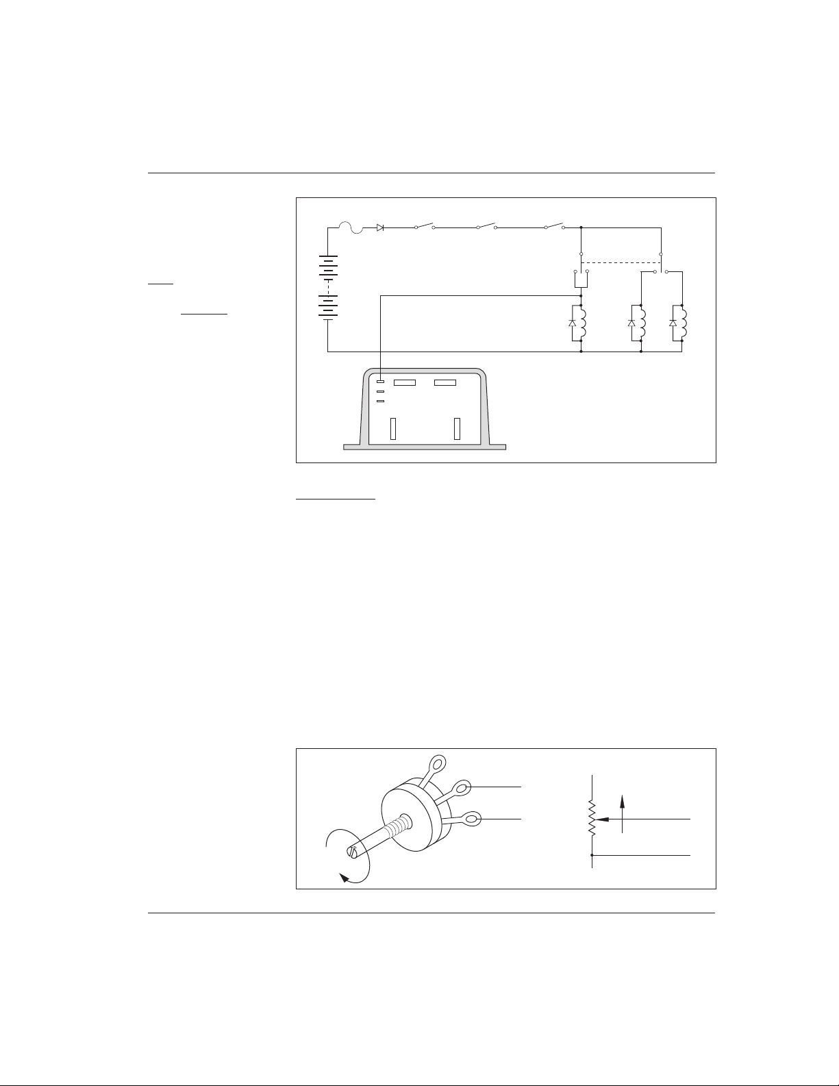
Figure 10 is a schematic diagram of the 1231C installation shown in Figure 8.
This wiring scheme isolates the control wiring in the driver’s compartment from
the high voltage connections of the power drive system, thus providing maximum
protection for the driver.
Fig. 10 Basic wiring configuration, Curtis PMC 1231C controller.
B- B+
A2
M-
+
–
MAIN
S2
A2S1A1
POTBOX
MAIN
KEYSWITCH
THROTTLE
MICROSWITCH
CONTROL
WIRING
FUSE
PRECHARGE
RESISTOR
CIRCUIT
BREAKER
TRACTION BATTERY
KSI RELAY
12V
AUXILIARY
BATTERY
KSI RELAY
+
–
KSI Wiring
The keyswitch input (KSI) circuit includes inputs from the keyswitch and from
the various interlocks. The controller KSI is used to turn the controller on and off.
KSI is turned on by connecting it to battery B+. Any positive voltage greater than
about 8 volts will turn on the controller, but usually the full vehicle battery voltage
is used.
In its simplest form, KSI is operated by a keyswitch that turns the vehicle off
and prevents unauthorized use. The keyswitch should also turn off the main
contactor and—in 1209B, 1221B, and 1221C applications—the forward/reverse contactors. This will act as a safety feature by removing power from the
motor control system when the keyswitch is off.
Interlocks (seat switches, battery charger interlocks, etc.) should be wired in
series so that they turn off the controller KSI and the contactor(s).
A keyswitch relay is recommended for high voltage systems. It should be
wired as shown in Figure 10. This relay prevents the full battery pack voltage

Curtis PMC 1209B/1221B/1221C/1231C Manual
16
from being brought into the operator compartment through the throttle microswitch, potentially exposing the operator to the high voltage source.
Forward/Reverse Wiring
The forward/reverse wiring schemes described here assume the power wiring
shown by the heavy lines in Figure 9. Some vehicles, especially those previously
using older, resistor-type controllers, may reverse the motor armature rather than
the field winding. Be careful if you are replacing this type of controller. When
using the Curtis PMC controller it is essential that the field be reversed and
that the armature be connected directly to the controller’s B+ and A2
terminals, because the plug diode inside is connected to these terminals.
Plug Braking
The standard forward/reverse control wiring (the thin lines in Figure 9) provides
plug braking. The forward/reverse switch should be in the positive feed to the
contactor coils, so that they can be turned off by the keyswitch, interlocks, and
throttle microswitch. The coil of one contactor or the other is energized to select
the direction desired. The contactor coils should have suppression diodes connected across them to improve switch contact life.
This is the recommended wiring for controllers with the HPD option, in
applications where plug braking is desired. If your controller does not have the
HPD option, however, we recommend that you use the alternate wiring shown
in Figure 11 (and described below) instead of the standard wiring; this alternate
wiring will provide arcless contactor operation.
NOTE: Plug braking is not recommended for on-road electric vehicles. The
plug braking feature is intended for material handling and low speed, low load
applications only.
Freewheeling: Wiring to Inhibit Plug Braking
If your controller has the HPD option, this feature can be used to inhibit plug
braking by briefly turning off the controller’s KSI input when the forward/reverse
switch goes through neutral. As shown in Figure 11, another set of contacts is
added on the forward/reverse switch. Therefore, a double-pole, double-throw
(DPDT) center-off switch must be used for this setup. A “hesitation switch” is
recommended, to ensure the switch is in neutral long enough to actuate HPD and
inhibit plug braking.
Plug braking can be reactivated during freewheeling by releasing the throttle
and reapplying it.
WIRING
Curtis PMC 1209B/1221B/1221C/1231C Manual
17
Fig. 11 Alternate
forward/reverse control
wiring, which provides
arcless contactor switching.
Wired this way with an
HPD controller, the
vehicle will freewheel;
with a non-HPD
controller, the vehicle will
plug brake.
A2M-
B-
B+
FORWARD
REVERSE
MAIN
KEYSWITCH
INTERLOCKS
THROTTLE
MICROSWITCH
FUSE
POLARITY
PROTECTION
DIODE
F/R SWITCH
(DPDT, center off)
+
–
WIRING
Fig. 12 Standard throttle
pot, 0–5kΩ.
Throttle Wiring
Standard Potbox Wiring
If the throttle input to the controller is from a Curtis PMC potbox or footpedal,
the wiring is simple: just connect the two wires of the potbox/footpedal cable to
the two push-on terminals of the controller, as shown in Figures 9 and 10. It
doesn’t matter which wire goes on which terminal. The wires can be extended as
required.
IMPORTANT: All vehicles should have throttle-actuated microswitches to
protect against runaways in the event the forward/reverse switch becomes
stuck in either direction. If your potbox doesn’t have such a microswitch
built in, you should add one.
Any suitable potentiometer of 5 kΩ nominal resistance will work with the
standard throttle input of the 1209B/1221B/1221C/1231C controllers. As
shown in Figure 12, connection should be made to the wiper and to one outer
terminal of the pot so that resistance increases as the throttle is applied.
TO
THROTTLE
INPUT
FASTER
0–5kΩ POT
TO
THROTTLE
INPUT
0–5k
Ω POT
FASTER
Curtis PMC 1209B/1221B/1221C/1231C Manual
18
WIRING
Fig. 13 Bi-directional
twist-grip throttle with a
standard 20 kΩ pot and a
controller with the
optional 5kΩ–0 throttle
input.
Pots for Twist-Grip Throttles
Twist-grip throttles either twist in only one direction (and are used only for
acceleration), or they twist both ways (and are also used for reversing, by means
of microswitches that select a direction contactor). For twist grips that twist in
only one direction, the controller throttle input can be from a 5 kΩ pot as shown
above in Figure 12.
For twist grips that twist both ways, a pot capable of going from zero in
neutral to 5 kΩ in each direction can be used. A mechanism can be designed to
make a standard pot turn in the same direction regardless of which direction the
twist grip is turned.
A third method of accommodating bi-directional twist-grip throttles uses a
standard potentiometer and a controller with a nonstandard throttle input. As
shown in Figure 13, a standard 20 kΩ pot is used, with its end terminals wired
together. The resistance goes
from 5 kΩ at neutral to zero at
the extremes: the opposite of the
standard throttle input configuration. Contact the factory if you
need this type of controller.
WARNING: with the input circuit shown in Figure 13,
potentiometer or wiring open
circuits turn off the controller’s
output. However, pot wiring shorts appear the same as a normal zero ohm
signal to the controller, and will produce full speed operation if the short occurs
while the power is on.
TO
THROTTLE
INPUT
20 kΩ POT
SPEED
INCREASES
BOTH WAYS
Curtis PMC 1209B/1221B/1221C/1231C Manual
19
WIRING
Electronic Throttle Wiring
Curtis’s electronic throttle, ET-XXX, is wired as shown in Figure 14. It requires
a 24–36V supply voltage and a controller with the optional 0–5V throttle input.
Fig. 14 Curtis electronic
throttle (ET series) with a
controller having the
optional 0–5V throttle
input.
A2M-
B-
B+
FORWARD
REVERSE
MAIN
KEYSWITCH
INTERLOCKS
FUSE
POLARITY
PROTECTION
DIODE
+
–
GREEN
ORANGE
BLACK
BLACK/WHITE
WHITE
WHT/BRN
WHT/GRN
Curtis PMC 1209B/1221B/1221C/1231C Manual
20
WIRING
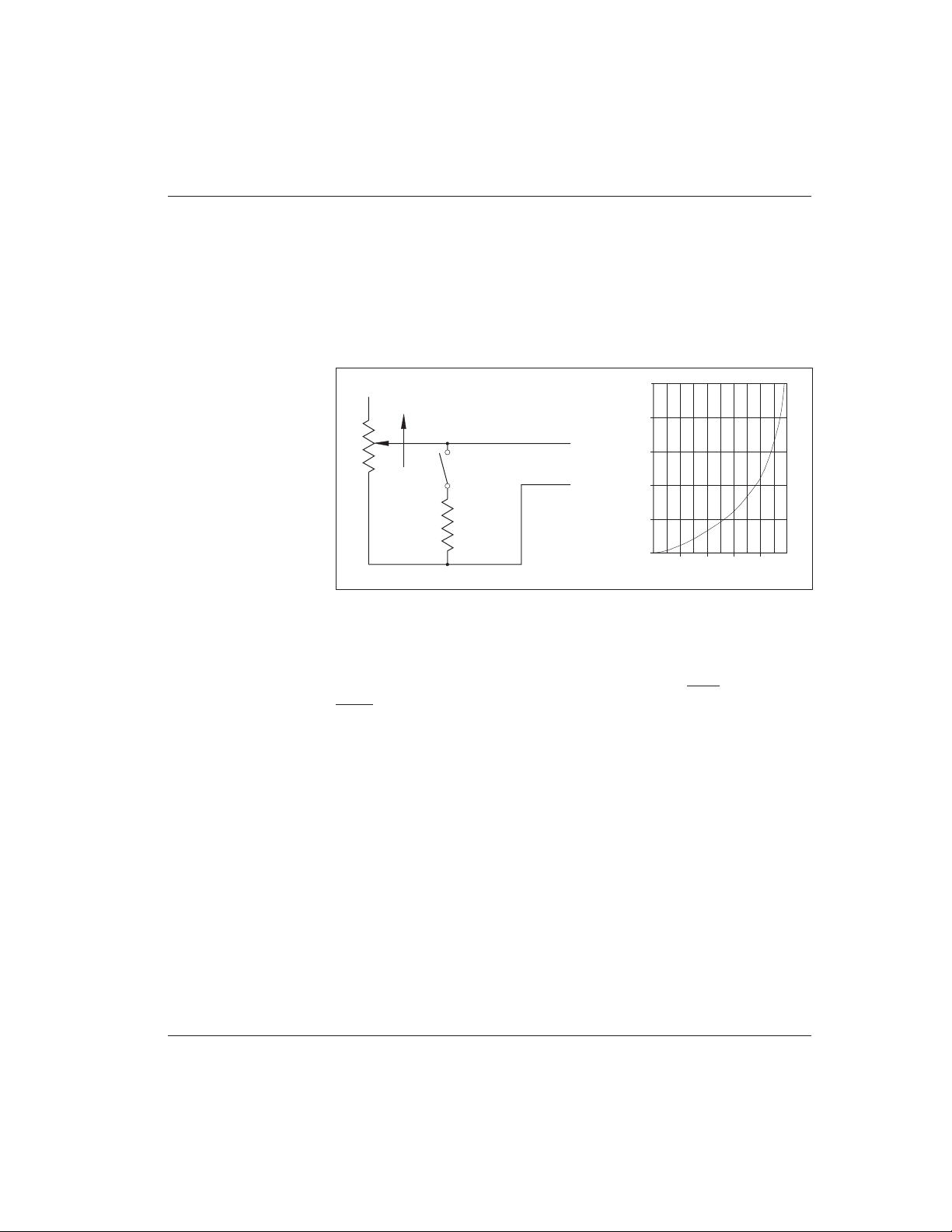
Fig. 15 Reduced speed
operation (with standard
0–5kΩ pot).
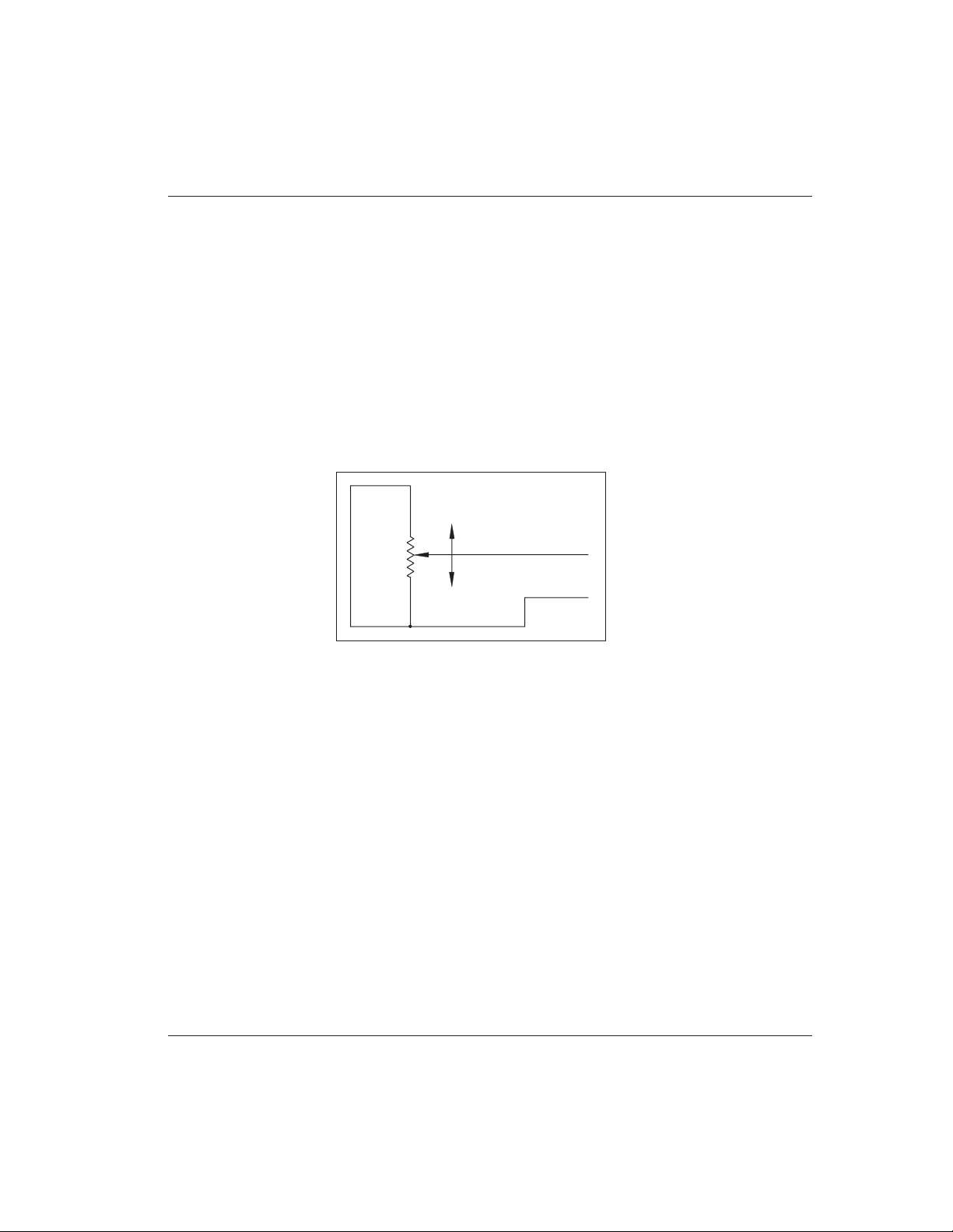
Reduced Speed Operation
Vehicle top speed can be easily limited, for safety or other reasons. A single resistor
connected in parallel with the throttle pot will reduce maximum speed according
to its resistance value, as shown in Figure 15. Use of a variable resistor makes
adjustment of maximum speed easier. With a switch, speed can be limited in
reverse only, or the speed reduction can be switched off—for example, to allow
authorized personnel to run the vehicle outdoors at full speed.
The speed reduction shown in the curve is approximate. The actual vehicle
top speed will depend on the motor characteristics and the vehicle load. You
should determine by experiment the proper resistor value to give the desired speed
reduction. (NOTE: With reduced speed operation, only top speed is reduced; full
power is maintained for starting at low speeds.)
Unlike resistor controllers, Curtis PMC controllers operate efficiently in the
reduced speed mode, because little power is lost through the controller.
TO
THROTTLE
INPUT
SPEED
REDUCTION
RESISTOR
FASTER
OPTIONAL
SWITCH
SPEED REDUCTION RESISTOR
(k ohms)
APPROX. % OF ORIGINAL TOP SPEED
0 20 40 60 80 100
25
20
15
10
5
0
0–5kΩ POT

Curtis PMC 1209B/1221B/1221C/1231C Manual
21
WIRING
Fig. 16 Throttle ramp
shapes.
THROTTLE RESISTANCE
DUTY CYCLE (percent)
No Ramp Shape
Inverse Ramp Shape
Ramp Shape
Super Ramp Shape
100
90
80
70
60
50
40
30
20
10
0
5 kΩ2.5 kΩ
0
Throttle Ramp Shaping
Throttle ramp shaping affects the PWM output response relative to the throttle
position. The more ramp shaping the throttle circuitry has, the more control the
operator has over low speed. Therefore, there is a smaller change in output duty
cycle relative to a specific amount of change in throttle output. An example set
of throttle ramp shaping responses is shown in Figure 16. The various ramp
shaping options shown in the figure are not all available on all controllers. Call
your local dealer or Curtis office for details.

Curtis PMC 1209B/1221B/1221C/1231C Manual
22
WIRING
☞
C A U T I O N
INSTALLATION CHECKOUT
Carefully complete the following checkout procedure before operating the vehicle. If a step does not test correctly, use the troubleshooting guide (Section 5)
to identify the problem.
Put the vehicle up on blocks to get the drive wheels off
the ground before beginning these tests.
Don’t let anyone stand in front of or behind the vehicle
during the checkout.
Make sure the keyswitch is off and the vehicle is in
neutral before beginning.
Wear safety glasses and use well-insulated tools.
A. Connect the battery. Use a voltmeter to verify that the proper voltage and
polarity appears at the battery B+ and B- terminals.
B. Check the voltage at the controller B+ and B- bus bars. You should see
approximately 90% of full battery voltage. (We assume that your system has the
recommended precharge resistor in parallel with the main contactor.)
C. If “A” and “B” do not check out, troubleshoot the wiring connections. Do
not proceed until the trouble is corrected and “A” and “B” check out.
D. With the forward/reverse switch in neutral, turn on the keyswitch. If the
motor runs without the throttle being applied, turn the keyswitch off and recheck
the wiring. If the motor does not run without the throttle applied, proceed with
the checkout.
E. Select a direction and slowly apply the throttle; the motor should now
respond. Look to see which direction the wheels are turning. If the wheels are
going the wrong way, turn everything off and interchange the motor field
connections.
F. If you have HPD, check it next. Turn off the keyswitch and direction switch.
Apply the throttle, turn the keyswitch on, and then select a direction. The motor
should not run. Release the throttle and re-apply it. The motor should now run.
If the motor runs before you release the throttle, recheck the wiring.

Curtis PMC 1209B/1221B/1221C/1231C Manual
23
WIRING
G. Take the vehicle down off the blocks and drive it in a clear area. It should have
smooth acceleration and good top speed.
H. On vehicles that are intended to plug brake, test the plug braking by driving
forward at moderate speed and shifting into reverse without letting up on the
throttle. The vehicle should smoothly brake to a stop and accelerate in reverse.
I. On vehicles that are intended to have plug braking inhibited, verify that the
maneuver in “H” produces freewheel coasting.

Curtis PMC 1209B/1221B/1221C/1231C Manual
24
MAINTENANCE & ADJUSTMENT
4
☞
C A U T I O N
MAINTENANCE & ADJUSTMENT
Curtis PMC 1209B/1221B/1221C/1231C controllers and potboxes require
only minimal maintenance if properly installed. NOTE: The controllers are sealed
and thus are not field serviceable.
CONTROLLER
Maintenance
It is recommended that the following two steps be performed occasionally. First
remove power by disconnecting the battery, and discharge the capacitors in
the controller (with a light bulb or a 2–10 Ω, 25 W resistor connected for a few
seconds across B+, B-). Follow good safety practices: get the vehicle drive wheels
off the ground, wear safety glasses, and use insulated tools (see page 2).
1. Make sure the electrical connections to the controller (and to the motor,
contactors, etc.) are tight. When checking the controller bus bar connections for tightness, use two opposing wrenches. This double-wrench
technique will help avoid putting stress on the bus bars, which could
crack the seals. Always use insulated wrenches.
2. Inspect all seals at the front and back of the controller. If necessary, use
a moist rag to wipe these areas clean enough so that you can see the seals.
Look for cracks and other signs of seal damage.
If the seals are intact, clean the controller thoroughly either by
washing it off or by wiping it clean with a moist rag. Power must not be
reapplied until the controller terminal area is completely dry.
If the seals have been damaged, there are several possible causes.
Perhaps the double-wrench technique was not used when the cables were
installed. Perhaps the vehicle’s environment requires that the controller
be better protected: either by mounting it in a different location, or by
installing a protective cover.
Damaged seals can lead to faulty operation. We strongly recommend replacing controllers that have faulty seals.
Adjustment
Some controllers allow adjustment of the plug braking current, current limit, and
acceleration rate settings. The adjustment pots on these models are located as
shown in Figure 17.
Curtis PMC 1209B/1221B/1221C/1231C Manual
25
MAINTENANCE & ADJUSTMENT
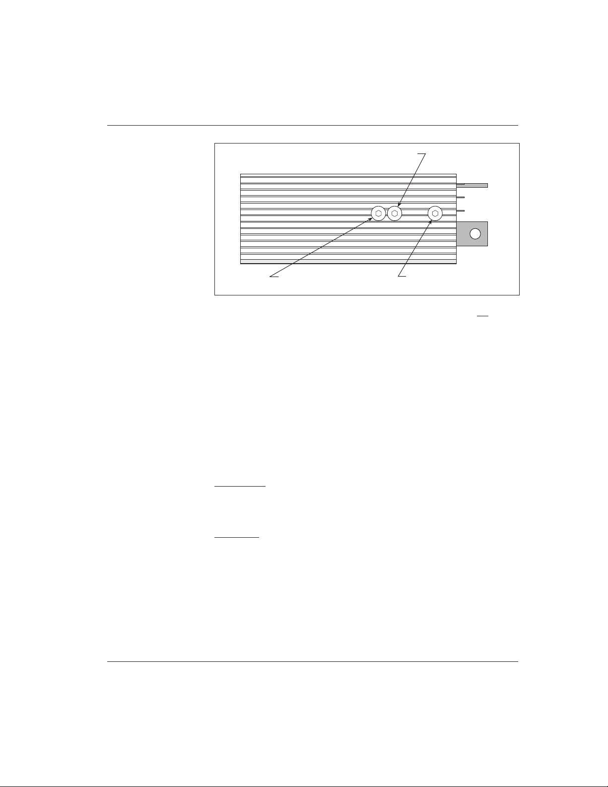
Fig. 17 Adjustment pots.
Use the following adjustment procedure. The keyswitch should be off during
adjustment.
1. Remove the socket head screw (1/8" Allen) for the adjustment you
want to make.
2. Adjust the internal potentiometer using a small insulated screwdriver
(available from Curtis).
3. Replace the socket head screw and nylon seal washer. To prevent
stripping, do not over-tighten.
POTBOX
Maintenance
Potbox maintenance is similar to controller maintenance: inspect for integrity of
connections and mounting, and clean (with a moist rag) as required.
Adjustment
Curtis PMC potboxes are factory set and rarely require user attention. To test and
adjust, connect an ohmmeter to the potbox wires and use this procedure:
1. With the spring holding the lever arm against the return stop, the
resistance should be less than 50 ohms. Slowly move the lever. If the
resistance abruptly starts to increase when the lever is 3 mm (1/8") from
the stop (1.5 mm [1/16"] for potboxes without the microswitch), no
adjustment is needed.
PLUG CURRENT ADJUST
(CW = higher plug current)
ACCELERATION RATE ADJUST
(CW = faster acceleration)
CURRENT LIMIT ADJUST
(CCW = lower current limit)

Curtis PMC 1209B/1221B/1221C/1231C Manual
26
MAINTENANCE & ADJUSTMENT
2. If adjustment is required, loosen the screw holding the lever on the pot
shaft. Use a screwdriver to rotate the pot shaft slightly with respect to
the lever. Recheck the point at which the resistance starts to increase
and continue making adjustments until the increase starts at 3 mm
(1/8") [at 1.5 mm (1/16") for potboxes without the microswitch].
When adjustment is correct, tighten the screw holding the lever on the
pot shaft, then recheck to see that this action did not disturb the
adjustment. Make sure that the lever is still seated down on the pot shaft
below the slight bevel on the end of the shaft.
3. Check the resistance with the lever pushed all the way to the other stop.
It should be between 4500 and 5500 ohms. If it is outside this range,
the potbox is faulty and should be replaced.
4. For potboxes equipped with a microswitch, check for correct switch
operation. Use an ohmmeter, or simply listen for the slight click the
switch makes. It should operate when the lever is 1.5 mm (1/16") from
the return stop. If it does not, adjust by loosening the two screws
holding the slotted microswitch mounting plate to the stop spacers and
moving the plate. Recheck the switch operating point after tightening
the screws.

Curtis PMC 1209B/1221B/1221C/1231C Manual
27
TROUBLESHOOTING & BENCH TESTING
TROUBLESHOOTING
AND BENCH TESTING
Some behaviors that may seem to suggest controller malfunction do not, in fact,
indicate a problem but rather are typical of normal operation. Before undertaking the
diagnostic tests, check to see whether your problem is addressed in the first section,
“Operational Notes.”
The diagnostic tests are designed to enable you to determine whether the trouble
is in the controller or in some other part of the motor control circuitry. The controllers
themselves are sealed and not field serviceable; contact your local dealer or
Curtis office if the problem is in the controller. The diagnostic section provides
enough detail to enable you to track circuitry problems to their source and repair them.
Finally, the bench tests will allow you to confirm controller operation in a simple,
low-power test configuration. Bench testing is primarily intended for checking out a
number of controllers on a regular basis.
OPERATIONAL NOTES
Noise
Controller operation is normally silent, with three exceptions: (1) A 1 kHz tone
may be heard during plug braking. This noise is normal and indicates that
plugging is taking place. The noise will stop when plug braking stops. (2) The
same noise may indicate overtemperature. The controller shifts frequency during
overtemperature from its normal 15 kHz to 1 kHz (1.5 kHz on “C” controllers),
providing an audible tone to alert the operator to the overtemperature condition.
(3) The frequency shifting feature on “C” controllers produces a 1.5 kHz tone
during the first 15% duty cycle of the PWM output. This tone may be heard
during low throttle, slow speed maneuvering.
Inability of Material Handling Vehicle to Plug Brake to a Stop on a Steep Ramp
If a material handling vehicle is rolling backwards down a steep ramp in reverse
and the throttle is applied demanding forward drive, the controller will attempt
to plug the vehicle to a stop. If the ramp is so steep that the plugging current
setpoint is insufficient to stop the vehicle, it will continue to be braked but will
nevertheless roll down the ramp. If the mechanical brakes are applied, and the
vehicle is stopped, the full drive current will be available when the throttle is
applied and the vehicle will proceed up the ramp.
5

Curtis PMC 1209B/1221B/1221C/1231C Manual
28
TROUBLESHOOTING & BENCH TESTING
☞
C A U T I O N
Working on electric vehicles is potentially dangerous. You should
protect yourself while performing the diagnostic tests by jacking up
the vehicle to get the drive wheels off the ground, opening the battery
circuit before working on the motor control circuit, wearing safety
glasses, and using properly insulated tools (see page 2).
Sluggish Vehicle Behavior
Loss of power will be noticeable when the batteries become overly discharged.
This is a normal response to low battery voltage. Curtis PMC 1209B/1221B
controllers are designed to protect against damage caused by low batteries. On
24–36 volt models, power to the motor is cut back when the voltage goes below
16 volts. Refer to the specifications (Appendix C) for other models.
Hot Controller
If the controller gets hot, it does not necessarily indicate a serious problem. Curtis
PMC 1209B, 1221B, and 1221C controllers protect themselves by reducing
power to the motor if their internal temperature exceeds 75°C (167°F). The
1231C controller begins reducing power at 85°C (185°F). Power output will be
reduced for as long as the overheat condition remains, and full power will return
when the unit cools.
In typical applications, overheating will rarely be a problem. However,
vehicle overloading may cause overheating, particularly if the controller is mounted
so that heat cannot be conducted away from its case or if other heat-generating
devices are nearby. If thermal cutback occurs often during normal operation, the
controller is probably undersized and should be replaced with a higher current
model.
IN-VEHICLE DIAGNOSTIC TESTS (TROUBLESHOOTING)
These tests require a general purpose volt ohmmeter. You can use either a
conventional “V-O-M” or an inexpensive digital voltmeter.
The troubleshooting chart (Figure 18) serves as a guide to the procedures
that follow. Before starting these tests, refer to the appropriate wiring diagrams
and make sure your controller is hooked up properly.

Curtis PMC 1209B/1221B/1221C/1231C Manual
29
TROUBLESHOOTING & BENCH TESTING
Fig. 18 Guide to troubleshooting procedures. [To use this guide, refer to the specified PROCEDURES that follow.]
D
if NO
if NO
if NO
1-D
1-D
1-C
2-D
2-D
2-E
3-A
3-C
3-E
3-B
3-C
3-E, F
4-C
4-D, E
4-F, G, H, I
Check voltage at CONTROLLER B- and BATTERY B+ terminals.
It should read full voltage for system.
1-A, B, C
if YES
Check voltage at CONTROLLER B- and CONTROLLER B+ terminals.
It should read 1 to 5 volts less than full battery voltage.
if NO
if NO
Check voltage at contactor and at KSI terminal.
Contactor should read full rated voltage, and KSI must be above 8V.
2-A, B, C
TEST
2 Check for main contactor operation and KSI
TEST
1 Check for power to the controller
TEST
3 Check potbox circuitry
(0–5kΩ throttles)
Check voltage across contactor power terminals.
There should be no measurable voltage drop.
if YES
if YES
Check resistance at potbox wires while depressing pedal.
Resistance should be between 0–50 ohms with pedal UP, and
4500–5500 ohms with pedal
DOWN
.
Check for shorts between potbox wires and vehicle frame.
Resistance should be at least 1 megohm.
Check voltage at upper throttle input terminal on controller.
Voltage should be 2.7 volts with pedal UP, and
7.0 volts with pedal
DOWN
,± a few tenths of a volt.
if YES
if YES
TEST
4 Check for controller output
if YES
4-A, B, C
if NO
if NO
if NO
Check voltage output while depressing pedal (B+ to M-).
Voltage should be zero with pedal UP, and full battery voltage
with pedal
DOWN
.
Check current in controller’s M- (motor field) lead while
depressing pedal.
Current should be high, and motor should turn.
Bad, discharged, or miswired
batteries, or corroded
connections.
TOO HIGH: contactor is welded.
TOO LOW: 250 Ω resistor or
controller is defective.
Trace flow to locate
problem.
If voltage drop occurs,
contactor is defective.
Defective potbox, broken wires
to potbox, or improper
mechanical operation.
If lower than 1 MΩ, wiring or
potbox is defective.
Controller is defective.
If no current, look for open
circuit. If current is high but
motor won’t turn, check motor,
wiring & plug diode.
Terminal area is probably
contaminated with acid or
dirt.

Curtis PMC 1209B/1221B/1221C/1231C Manual
30
TROUBLESHOOTING & BENCH TESTING
TEST
1 Check for power to the controller
1-A Leave the keyswitch off for these tests.
1-B Verify that battery (-) connects to the B- terminal of the controller. Connect
voltmeter (-) lead to this point.
1-C Connect voltmeter (+) to the battery side of the main contactor. Check for
full battery voltage. If it is not there, the trouble is in the battery pack, the
cables to it, or the power fuse.
1-D Connect the voltmeter (+) lead to the controller B+ terminal. You should
read a voltage 1 to 5 volts less than the full battery voltage. If this voltage is
zero or close to zero, the trouble is either a bad controller, a bad 250 Ω resistor
across the contactor, or an incorrectly connected cable between the contactor
and the controller. Trace the cable to make sure it is hooked up right.
Remove and test the 250 Ω resistor with an ohmmeter. If these check out,
the controller is malfunctioning. If you see full battery voltage at this point,
then the contactor has welded and must be replaced.
TEST
2 Check for main contactor operation and KSI
2-A Turn the key on, place the forward/reverse switch in forward or reverse, and
apply the throttle until its microswitch operates. (In these procedures, we
assume the throttle is equipped with the recommended microswitch.)
2-B This should cause the main contactor to operate with an audible click.
Connect the voltmeter across the contactor coil terminals. You should see
full battery voltage (minus the polarity diode drop).
2-C The controller KSI terminal should also be getting full battery voltage.
Verify this by connecting the voltmeter (-) to the controller’s B- terminal,
and the voltmeter (+) to the controller’s KSI terminal.
2-D If the contactor and KSI terminal are not getting voltage, that’s the problem.
Use the voltmeter to find out where it is not getting through. Connect the
voltmeter (-) to the controller’s B- terminal and check the following points
with the voltmeter (+) lead to trace the flow:

Curtis PMC 1209B/1221B/1221C/1231C Manual
31
TROUBLESHOOTING & BENCH TESTING
1. First, check both sides of the control wiring fuse.
2. Check both sides of the polarity protection diode to make
sure its polarity is correct.
3. Check both sides of the keyswitch.
3. Check both sides of the throttle microswitch.
4. Finally, check the contactor coil and controller KSI.
2-E If the contactor coil and KSI are getting voltage, make sure the contactor is
really working by connecting the voltmeter across its contacts (the big
terminals). There should be no measurable voltage drop. If you see a drop,
the contactor is defective. (We assume the recommended precharge resistor
is in place.)
TEST
3 Check the potbox circuitry
The following procedure applies to the standard throttle input configuration for
these controllers, which is a nominal 5kΩ pot connected as a two-wire rheostat (0
= full off, 5 kΩ = full on), and also to 5kΩ–0 configurations. If your installation
uses a controller with a throttle input other than 0–5kΩ or 5kΩ–0, find out what
its range is and use a procedure comparable to the one below to make sure your
throttle is working correctly.
3-A With the keyswitch off, pull off the connectors going to the throttle input
of the controller. Connect an ohmmeter to the two wires going to the
throttle and measure the resistance as you apply and release the throttle. The
resistance at the limits should be within these ranges:
RESISTANCE (in ohms)
STANDARD
0–5kΩ POT 5kΩ–0 POT
Zero throttle: 0 – 50 4500 – 5500
Full throttle: 4500 – 5500 0 – 50
3-B If these resistances are wrong, it is because the pot itself is faulty, the wires
to the pot are broken, or the throttle and its linkage are not moving the
potbox lever through its proper travel. Apply the throttle and verify that the
potbox lever moves from contacting the zero-throttle stop to nearly contacting the full-throttle stop. If the mechanical operation looks okay, replace the
potbox.

Curtis PMC 1209B/1221B/1221C/1231C Manual
32
TROUBLESHOOTING & BENCH TESTING
☞
C A U T I O N
3-C While you have the potbox wires off the controller, use an ohmmeter to
check for shorts between these wires and the vehicle frame. You should see
a resistance of at least 1 megohm. If it is lower than that, inspect the wiring
for damaged insulation or contact with acid. If necessary, replace the potbox.
3-D Push the wires back on the controller terminals. It doesn’t matter which wire
goes on which terminal.
3-E Inspect the terminal area of the controller closely. Occasionally a buildup of
dirt or acid residue of a conductive nature causes electrical leakage between
the throttle input terminals and the B- or M- terminals, leading to faulty
controller operation. To check for this problem, measure the voltage at the
appropriate throttle input terminal (the upper terminal for 0–5kΩ pots, the
lower terminal for 5kΩ–0 pots), by connecting the voltmeter (-) lead to the
controller’s B- terminal. The keyswitch must be on and a direction selected
for this test.
THROTTLE INPUT VOLTAGE (in volts)
STANDARD
0–5kΩ POT 5kΩ–0 POT
UPPER TERMINAL LOWER TERMINAL
Zero throttle: 2.7 3.1
Full throttle: 7.0 7.4
Compare your readings with these; if they are different by more than a few
tenths of a volt, contamination is probably the cause.
3-F Carefully clean off the terminal area of the controller with a cotton swab or
clean rag moistened with water, and dry thoroughly.
Be sure to turn everything off
before cleaning.
Now test the controller to see if proper operation is restored. If so, take steps
to prevent this from happening again: dirt and water must be kept from
reaching the terminal area of the controller. If the voltages are still out of
range, the controller is at fault and should be replaced.

Curtis PMC 1209B/1221B/1221C/1231C Manual
33
TROUBLESHOOTING & BENCH TESTING
TEST
4 Check for controller output
4-A The first step is to measure the output drive voltage to the motor at the
controller’s M- terminal.
4-B Connect the voltmeter (+) lead to the controller’s B+ terminal. Connect the
voltmeter (-) lead to the controller’s M- terminal.
4-C Turn on the keyswitch with the forward/reverse switch in neutral, and then
select a direction and watch the voltmeter as you apply the throttle. The
voltmeter should read zero (or close to zero) before you apply the throttle,
and should read full battery voltage with full throttle. If it does not, the
controller is defective and must be replaced.
4-D The next step is to measure the current in the controller’s M- lead. If you have
a means of measuring this high dc current, such as a shunt/meter setup or
a clamp-on dc ammeter, use it. If not, we recommend that you buy an
inexpensive ammeter of the type that is simply held against the wire being
tested. These are readily available at auto parts stores, and their accuracy is
adequate for this test.
4-E Turn on the keyswitch with the forward/reverse switch in neutral, and then
select a direction and watch the ammeter while applying the throttle.
4-F If you see no current flowing in the M- lead, the problem is an open circuit
in the motor or the wiring between the motor and the controller. Check the
forward/reverse switch. If your vehicle uses contactors for reversing, check
to see that they are operating and that their contacts are closing. If these are
okay, check the motor armature and field for opens.
4-G If you do see a high current flowing in the M- lead, but the motor does not
turn, the problem is a short in the motor circuit, a miswired motor, or a short
in the controller’s internal plug diode. Test the plug diode as follows:
1. Remove power by opening the battery circuit. Take the
cable off the controller’s A2 terminal.
2. Use an ohmmeter to check the resistance between the
controller’s A2 and B+ terminals. You are testing for the
presence of a diode inside the controller, so swap the two
leads of the ohmmeter and look for a low resistance one way
and a much higher one the other way. If your meter has a
diode test function, use it.

Curtis PMC 1209B/1221B/1221C/1231C Manual
34
TROUBLESHOOTING & BENCH TESTING
☞
C A U T I O N
3. If you find the diode to be shorted, the controller is
defective.
4-H Put the A2 cable back on the controller and reconnect the battery.
4-I If the plug diode is okay, there is a short in the motor circuit. The short could
be in the forward/reverse switch, so look there first. Because the resistance
of the motor is so low, the motor must be tested separately if it is suspected
of having a shorted winding.
BENCH TESTING
First, before starting any bench testing, pick up the controller and shake it. If
anything rattles around inside, the unit should be returned.
Protect yourself during bench testing. Wear safety glasses and use insu-
lated tools.
Equipment Needed
The simple setup shown in Figure 19 is required for testing these controllers on
the bench. You will need:
• a POWER SUPPLY with a voltage equal to the rating of the
controller you want to test. You can use either a string of batteries
or a regulated line-operated power supply. Because only low
power tests will be described, a 10 amp fuse should be wired in
series with the batteries to protect both operator and controller
against accidental shorts. A battery charger alone should not be
used as a power supply, because without a battery load its output
voltage may exceed the rating of the controller.
• a THROTTLE POTBOX. For controllers with the standard
throttle input configuration (a 5 kΩ pot wired as a two-terminal
rheostat), a Curtis PMC potbox or any 5 kΩ pot will work fine.
For controllers with other input options, use whatever kind of
throttle is used on the vehicle.
• a POWER SWITCH to disconnect all power from the test setup.
• a MAIN CONTACTOR with a 250 ohm, 5 watt resistor across
its high-power contacts and a KEYSWITCH to turn it on and
off.

Curtis PMC 1209B/1221B/1221C/1231C Manual
35
TROUBLESHOOTING & BENCH TESTING
Fig. 19 Setup for bench testing.
POWER SUPPLY
(to match your controller)
POTBOX
(to match your controller’s
throttle output)
TEST LOAD
(to match battery voltage)
MAIN
CONTACTOR
POWER
SWITCH
KEYSWITCH
10A
FU
SE
12V
12V
12V
5W, 250Ω
RESISTOR
• a TEST LOAD consisting of incandescent light bulbs wired in
series to get the same voltage as your power supply. (For example,
with a 36 volt battery, use three 12 volt bulbs.)
• a general purpose VOLT OHMMETER or DIGITAL VOLTMETER.

Curtis PMC 1209B/1221B/1221C/1231C Manual
36
TROUBLESHOOTING & BENCH TESTING
Bench Test Procedure
A. Hook up the controller as shown. Connect the voltmeter leads to the
controller’s B+ and B- terminals.
B. Turn on the power switch (not the keyswitch) and watch the voltmeter. Its
reading should build up slowly over several seconds to within a couple of volts
of full battery voltage. If this voltage does not come up, the controller is bad.
C. Now turn on the keyswitch. The main contactor should turn on and the
voltage at the controller’s B+ and B- terminals should now equal the full
battery voltage. Move the throttle through its range. The lamps should
increase in brightness.
D. If the controller has HPD, test this feature as follows:
1. Turn off the keyswitch.
2. Move the potbox lever to about halfway.
3. Turn the keyswitch switch on. Verify that the lamps do not
come on until the potbox lever is moved most of the way
toward OFF and then moved back up.
E. Test the controller’s throttle fault protection feature by pulling off one of the
potbox’s two connections to the controller’s throttle input terminals while
the lamps are on (potbox lever in the ON position). The lamps should turn
off. With the potbox lever still in the ON position, reconnect the wire. The
lamps should smoothly increase in brightness to their previous level.
F. Finally, remove the controller from the test setup and check its internal plug
diode, as described in Troubleshooting Procedure 4-G .

Curtis PMC 1209B/1221B/1221C/1231C Manual
37
GLOSSARY
6
GLOSSARY:
FEATURES and FUNCTIONS
Acceleration rate
A built-in acceleration rate circuit maintains a maximum rate of power increase
to the motor. If the throttle is applied full on at start-up, the acceleration rate
setting determines how quickly the controller output increases. The standard
setting is such that with the throttle full on, the controller requires approximately
one second to reach full output. This feature contributes to smooth, gentle starts.
The acceleration rate is adjustable via an externally accessible trimpot; see
Section 4 for adjustment instructions. The deceleration rate is fixed, and cannot
be adjusted.
Current limiting
Curtis PMC controllers limit the motor current to a preset maximum. This
feature protects the controller from damage that might result if the current were
limited only by motor demand.
The current limit feature also protects the rest of the system. Because high
current surges during vehicle acceleration are eliminated, stress on the motor and
batteries is reduced and their efficiency and service life are improved. Similarly,
there is less wear and tear on the vehicle drivetrain, as well as on the ground on
which the vehicle rides—an important consideration with golf courses and tennis
courts, for example.
The maximum motor current can be factory-set to a lower value than the
standard maximum, if requested. In addition, the current limit is field adjustable;
see Section 4 for adjustment instructions.
Current multiplication
During acceleration and during reduced speed operation, the Curtis PMC
controller allows more current to flow into the motor than flows out of the
battery. The controller acts like a dc transformer, taking in low current and high
voltage (the full battery voltage) and putting out high current and low voltage.
The battery needs to supply only a fraction of the current that would be required
by a conventional controller (in which the battery current and motor current are
always equal). The current multiplication feature gives vehicles using Curtis PMC
controllers dramatically greater driving range per battery charge.
Environmental protection
Curtis PMC 1209B/1221B/1221C/1231C controllers are housed in rugged
anodized aluminum extrusions that provide environmental protection. Controllers must be kept clean and dry, however, to ensure long life.

Curtis PMC 1209B/1221B/1221C/1231C Manual
38
GLOSSARY
ET-series electronic throttles
The ET-XXX is a wigwag-style throttle control assembly, manufactured by
Hardellet for Curtis. It provides a 0–5V signal in both the forward and reverse
directions along with high side coil drivers for the forward and reverse contactor
coils.
Frequency shifting
The frequency shifting feature is built into the “C” controllers (1221C and
1231C). It reduces the operating frequency from 15 kHz to 1.5 kHz when the
PWM output is less than ≈15%. Frequency shifting improves the current limit
control and also helps protect the controller when the motor is in near-stall
conditions.
NOTE: Operating an electric drive system in stall or near-stall conditions puts
high current and thermal stresses on the motor and controller. This is not
considered a normal operation and is not recommended.
High pedal disable (HPD)
[OPTIONAL FEATURE]
By preventing the vehicle from being turned on with the throttle applied, HPD
ensures the vehicle starts smoothly and safely. If the operator attempts to start the
vehicle when the throttle is already applied, the controller (and the vehicle) will
remain off. For the vehicle to start, the controller must receive an input to KSI
before receiving a throttle input. In addition to providing routine smooth starts,
HPD also protects against accidental sudden starts if problems in the throttle
linkage (e.g., bent parts, broken return spring) give a throttle input signal to the
controller even with the throttle released.
The 1209B/1221B/1221C/1231C controllers are available either with or
without the HPD feature.
KSI
KSI (Key Switch Input) provides power to the controller’s logic circuitry via both
the keyswitch and the throttle microswitch. KSI should be used to turn the
controller on and off.
MOSFET
A MOSFET (Metal Oxide Semiconductor Field Effect Transistor) is a type of
transistor characterized by its fast switching speeds and very low losses.
Overtemperature
See Thermal protection.

Curtis PMC 1209B/1221B/1221C/1231C Manual
39
GLOSSARY
Overvoltage cutoff
Overvoltage cutoff inhibits the PWM and opens the contactors, preventing
operation when battery voltages are too high for proper functioning. This protects
the controller and motor from possible damage due to the overvoltage condition.
Overvoltage can result during battery charging or from an improperly wired
controller. Controller operation resumes when the voltage is brought within the
acceptable range. The cutoff voltage and re-enable voltage are percentages of the
battery voltage and are set at the factory.
Plug braking
The vehicle can be braked electrically by selecting the opposite direction with the
forward/reverse switch without releasing the throttle. When the motor is reversed,
the armature acts as a generator; the controller regulates the current in the motor
field winding to give an appropriate level of plug braking torque. The vehicle
brakes smoothly to a stop, then accelerates in the other direction. (NOTE: The
controller may be unable to provide plug braking if the vehicle is moving too
slowly for the motor to generate the necessary plug braking current.)
The plug current limit is factory set to meet customer requirements. In
addition, the plug current limit is adjustable via an externally accessible trimpot;
see Section 4 for adjustment instructions.
Two types of plug braking control are available: variable and fixed. Variable
plug braking allows the amount of plug braking to be adjusted via the throttle.
When direction is reversed, the plug braking current increases as a function of the
throttle position. Maximum plug braking will occur at maximum applied throttle.
Fixed plug braking, on the other hand, applies the specified amount of braking
when the direction is reversed regardless of the amount of throttle applied.
If plug braking is not desired, the vehicle can be wired so that moving the
forward/reverse switch through neutral causes the vehicle to freewheel as long as
the accelerator is applied. If the throttle is released and reapplied, plug braking
will then occur. To inhibit plug braking in this way, your controller must have
the optional HPD feature. Wiring details are provided in Section 3.
A 1 kHz tone may be heard during plug braking. This noise is normal and
indicates that plugging is taking place. The noise will stop when the plug braking
stops.
NOTE: Plug braking is not recommended for on-road electric vehicles. The
plug braking feature is intended for material handling and low speed, low load
applications only.
Pot fault
See Throttle pot fault protection.

Curtis PMC 1209B/1221B/1221C/1231C Manual
40
GLOSSARY
PWM
PWM (Pulse Width Modulation), also called “chopping,” is a technique that
switches battery voltage to the motor on and off very quickly, thereby controlling
the speed of the motor. Curtis PMC 1200 series controllers use high frequency
PWM—15 kHz—which permits silent, efficient operation. PWM is described in
more detail in Appendix B.
Smooth, stepless operation
Like all Curtis PMC 1200 Series controllers, 1209B/1221B and 1221C/1231C
models allow superior operator control of the vehicle’s drive motor speed. The
amount of current delivered to the motor is set by varying the “on” time (duty
cycle) of the controller’s power MOSFET transistors. This technique—pulse
width modulation (PWM)—permits silent, stepless operation.
Temperature compensation
Internal temperature compensation ensures that the controller’s current limit
remains constant over varying controller temperatures. This eliminates performance variations resulting from variations in controller operating environment
temperatures.
Thermal protection
Because of their efficiency and thermal design, Curtis PMC controllers should
barely get warm in normal operation. Overheating can occur, however, if the
controller is undersized for its application or otherwise overloaded. If the internal
temperature of the 1209B, 1221B, and 1221C controllers exceeds 75°C (167°F),
the main and plug current limits decrease steadily until they are reduced to zero
at 95°C (200°F). Thermal cutback for the 1231C controller begins at 85°C
(185°F). At the reduced performance level, the vehicle can be maneuvered out of
the way and parked. The controller shifts frequency during overtemperature from
its normal 15 kHz to 1 kHz (“B” models) or 1.5 kHz (“C” models), providing an
audible tone alerting the operator to the overtemperature. (NOTE: The plug
current limit can be made independent of temperature. This ensures full braking
capability even in overtemperature conditions. However, it may result in premature plug diode failure due to excessive thermal stresses.)
Full current limit and performance return automatically after the controller
cools down. Although this action is not damaging to the controller, it does
suggest a mismatch. If thermal cutback occurs often in normal vehicle operation,
the controller is probably undersized for the application and a higher current
model should be used.
The controller is similarly protected from undertemperature. Should its
internal temperature fall below -25°C (-13°F), the current limit decreases to

Curtis PMC 1209B/1221B/1221C/1231C Manual
41
GLOSSARY
approximately one-half of the set current. When the controller warms up, full
current limit and performance return automatically.
Throttle microswitch
Curtis PMC potboxes and footpedals are typically equipped with microswitches.
It is recommended that these switches be used to open the main contactor and the
controller’s KSI input when the throttle is fully released. This adds a level of safety
protection by disconnecting battery power from the motor and controller whenever the operator releases the throttle. If you are not using a throttle with a builtin microswitch, it is recommended that you add one to your system.
Throttle pot fault protection (runaway protection)
To prevent uncontrolled operation, these controllers shut off the motor in the
event of an open circuit fault in the throttle or its wiring. The standard
configuration is a two-wire pot ranging from 0 ohms for full off to 5000 ohms for
full on; if the controller detects an abnormally high throttle input (more than
about 1.5 times the normal input resistance), it shuts off its output to the motor,
thus preventing a runaway. The controller returns to normal operation when the
fault (e.g., broken potbox wiring, broken connectors) has been repaired.
Undertemperature
See Thermal protection.
Undervoltage protection
The control circuitry requires a minimum battery voltage to function properly.
The controller is therefore designed so its output is gradually reduced if the
battery voltage falls below a certain level. Cutback voltages for the various models
are listed in the specifications (Appendix C). Reducing the output to the motor
allows the battery voltage to recover, and an equilibrium is established in which
the battery supplies as much current as it can without falling below the cutback
voltage.

Curtis PMC 1209B/1221B/1221C/1231C Manual
42
APPENDIX A
APPENDIX A
FUNCTIONAL DESCRIPTION
A-1
These controllers consist of a POWER SECTION and a LOGIC SECTION, which drives the power section.
POWER SECTION
An array of paralleled power metal oxide semiconductor field effect transistors (MOSFETs) switches pulses
of current from the battery to the motor. During the interval when the MOSFETs are off, the motor current
continues to flow in the freewheel diode, which is actually a number of paralleled fast recovery rectifiers. An
array of filter capacitors connected directly across the battery provides the instantaneous current required by
the power switching circuitry and in this way provides battery ripple current filtering and voltage spike
suppression. The plug diode provides a path for armature current to flow during plug braking.
Fig. A-1 Block diagram, Curtis PMC 1209B/1221B/1221C/1231C controllers.
+14V
REGULATOR
UNDER
VOLTAGE
DETECT
SWITCH
PLUG DIODE
PLUG
DETECT
PULSE
WIDTH
MODULATOR
CURRENT
LIMIT
COMPARATORS
CURRENT
LIMIT
REFERENCE
CURRENT
LIMIT
DISABLE
SHUT
DOWN
GATE
DRIVE
LIMIT
INTEGRATOR
ACCELERATION
CIRCUIT
THROTTLE
INPUT
SCALING
HIGH
PEDAL
DISABLE
START-UP
TIMER
POT
FAULT
OVER
TEMP
UNDER
TEMP
TEMP
SENSE
POWER
SECTION
LOGIC SECTION
B+
A2
M-
B-
FREEWHEEL
DIODE
S1
S2
FIELD
+
FILTER
CAPACITORS
OSCILLATOR
MOSFETs
A1
A2
+
–
ACCELERATION
RATE ADJUST
+14 VOLTS
TO ALL CIRCUITS
ARM
THROTTLE
POT
THROTTLE
INPUT
(SHADED AREA REPRESENTS CONTROLLER)
CURRENT LIMIT
ADJUST
PLUG CURRENT
LIMIT
REFERENCE
PLUG
CURRENT
ADJUST
FIXED PLUGVARIABLE PLUG
+10V
REGULATOR
+10V REFERENCE
KSI
KEYSWITCH
and
INTERLOCKS
OVER
VOLTAGE
DETECT

Curtis PMC 1209B/1221B/1221C/1231C Manual
43A-2
APPENDIX A
LOGIC SECTION
B- is the ground return for all of the logic and auxiliary circuitry. For systems over 12 volts, the battery supply
is regulated down to 14 volts to power the logic circuitry. The output of the 14 volt regulator is switched on
and off (switch) by the keyswitch input (KSI) to power up the control circuitry when the vehicle is in use and
to power it down (shutdown) when the vehicle is not in use.
The speed control input (throttle input) is usually a 5000 ohm, two-wire pot, but other types can be
accommodated, so a flexible throttle input scaling circuit conditions the control input to a standard level. This
standardized throttle input goes to the acceleration circuit, which limits the rate at which the controller
output can increase. The acceleration rate is set by a resistance, and is adjustable via a user accessible trimpot
(acceleration ramp adjust).
The output of the throttle input scaling also goes to a pot fault circuit, which turns the controller output off
in the event of inputs (e.g., broken wires) that would otherwise cause a runaway. An optional protective
feature, high pedal disable (HPD), inhibits controller output if the controller is turned on with the throttle
applied. After an interval measured (start-up timer) from the moment the KSI input is turned on, the HPD
circuit checks the throttle position. If an applied throttle condition is detected, controller output is held off
until the throttle input is returned to zero and then normal operation is allowed.
The control signal then goes to the limit integrator, which reduces the controller output in response to
undervoltage, overvoltage, or overcurrent. The time-averaged response of this circuit gives a stable limiting
action. The throttle output from the limit integrator is also fed to the oscillator to determine the operating
frequency. On “C” models, the controller operates at 1.5 kHz for throttle requests less than 15% output and
at 15 kHz for throttle requests greater than 15% output. The undervoltage detector gives an output when the
battery voltage is too low. The reduction in output allows the battery voltage to recover and an equilibrium
to be established at a voltage high enough to allow the controller to function properly. The overvoltage
detector produces an output when battery voltage is too high (e.g., overcharged batteries) to protect the
controller from excessive voltage transients. The current limit function is explained in more detail below.
The heart of the logic circuitry is the pulse width modulator in which the control input derived from the
previous stages is compared in magnitude to a 15 kHz sawtooth wave from the oscillator. The resulting pulse
output can be smoothly varied between full off and full on. These pulses become the input to the controller’s
main power MOSFET switch via a gate drive circuit that provides the high pulse currents needed to turn the
power MOSFETs on and off (see Fig. B-1). The shape of the sawtooth wave can be altered so that most of
the pulse width change occurs in the earlier or in the latter part of the control input range, giving more
sensitive throttle response at high or at low speeds.
Current limiting is done by sensing the voltage drop across the main power MOSFET switch when it is on.
This voltage is compared (current limit comparators) with a current limit reference; when it exceeds the
reference, an overcurrent signal acts on the limit integrator to reduce the controller output and thus hold the
current at the limit. Because the voltage across the power MOSFET switch is high when it is off, the current

Curtis PMC 1209B/1221B/1221C/1231C Manual
44A-3
APPENDIX A
limit comparison is inhibited during the off interval by the current limit disable circuit. The current limit is
set as follows:
1. During manufacture, the current limit is set to the model’s nominal rating; it is also
user-adjustable by a trimpot (current limit adjust) to currents lower than the nominal
rating.
2. During operation at extreme high or low temperatures, current limit is reduced to
protect the controller from damage. From a thermal sensor (temp sense) on the
heatsink, signals are produced to cut back the current limit at temperatures above
75°C (above 85°C for the 1231C) or below -25°C (overtemp, undertemp). The
controller’s operating frequency shifts to 1 kHz (“B” models) or 1.5 kHz (“C”
models) during overtemperature operation, producing an audible tone to alert the
operator.
3. During plug braking operation, the current limit is reduced to give an appropriate
motor braking torque. The plug braking current is set during manufacture; it is also
user-adjustable by a trimpot (plug current adjust).
4. The fixed plug option provides one level of plug braking current independent of
throttle position (provided it is at least minimally applied). For the fixed plugging
option, the plug current limit reference is derived from the current limit reference.
5. The variable plug option provides variable plug braking current corresponding to the
position of the throttle. This allows much smoother braking under control of the
operator. For the variable plugging option, the plug current limit reference is derived
from the throttle input scaling.
The transition to the plug braking mode is detected (plug detect) by monitoring the voltage across the plug
diode. When this diode becomes forward biased, it indicates that the motor field has been reversed and the
controller has gone into plug mode. The current limit is reduced as described, and the frequency of the
oscillator is reduced from 15 kHz to 1 kHz, to allow finer control of the controller output while plugging.
During plug braking operation, the acceleration circuit is reset to a low level so that when drive operation
resumes, the controller will go through a normal acceleration ramp. When the motor has come to a stop, the
plug diode will again become reverse biased and the controller will revert to normal drive operation.
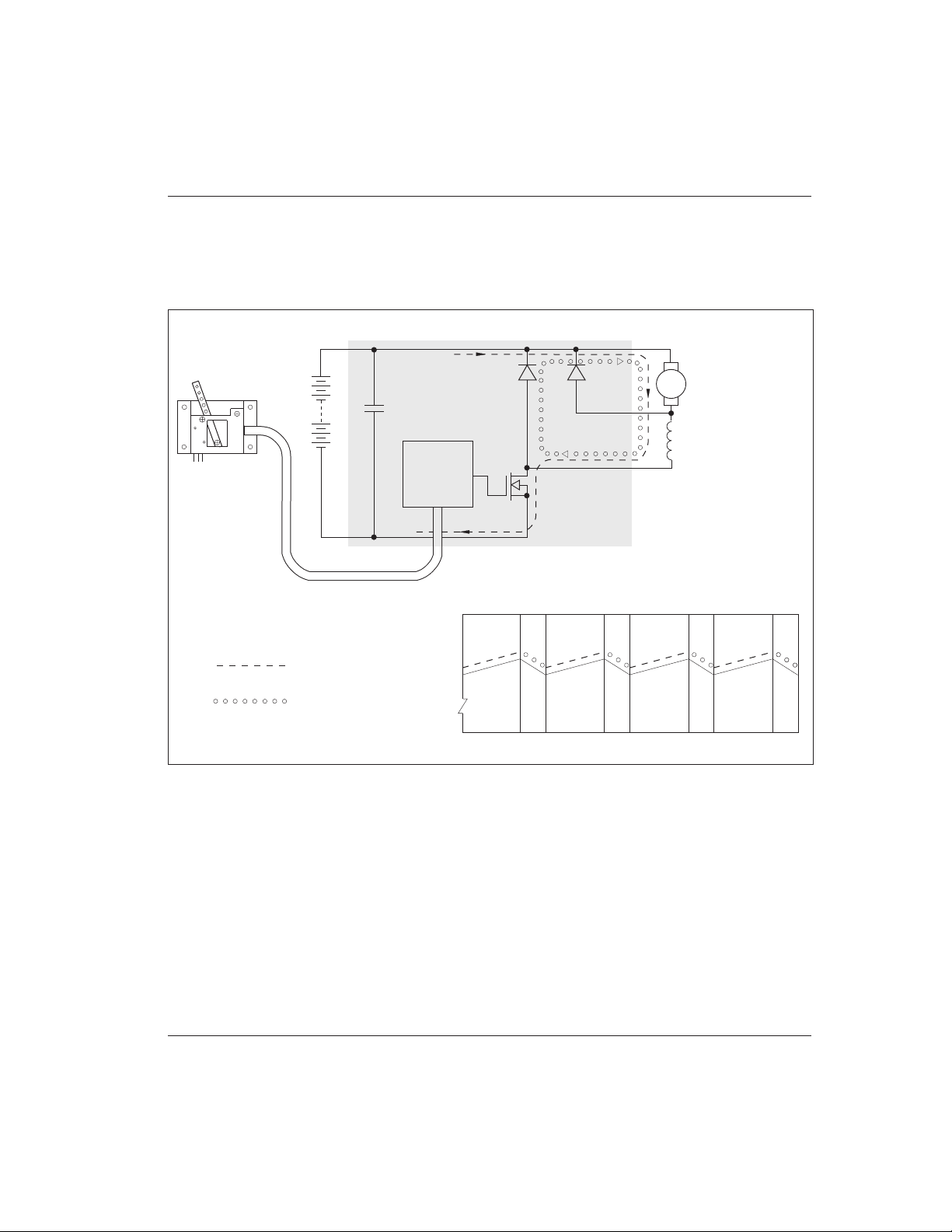
Curtis PMC 1209B/1221B/1221C/1231C Manual
45
APPENDIX B
APPENDIX B
PULSE WIDTH MODULATION
B-1
A high power semiconductor switch, consisting of an array of parallel power MOSFET transistors, controls
the current in the motor windings. The transistors are connected in series with the battery and the motor. The
transistors are turned on and off 15,000 times per second by the controller circuitry, while the ratio of the on/
off times is varied in response to the input demanded by the throttle.
When the transistors are on, the current through the motor builds up, storing energy in the motor’s magnetic
field. When the transistors are off, the stored energy causes the motor current to continue to flow through the
freewheel diode. The control current ramps up and down as the switch turns on and off. Average current,
which determines motor torque, is controlled by the ratio of on/off times. Smooth, stepless control of the
power delivered to the motor is achieved with almost no power loss in the control components.
Fig. B-1 Pulse width modulation.
+
–
+
THROTTLE
POTBOX
FILTER
CAPS
POWER
MOSFETS
MOTOR
FIELD
PLUG
DIODE
FREEWHEEL
DIODE
ARM
TIME
MOTOR CURRENT
CURRENT PATH DURING
TRANSISTOR
ON TIME
CURRENT PATH DURING
TRANSISTOR OFF TIME
BATTERY
CONTROL
CIRCUITRY
(SHADED AREA REPRESENTS CONTROLLER)
B+
B-
A2
M-

Curtis PMC 1209B/1221B/1221C/1231C Manual
46
APPENDIX C
Table C-1 ELECTRICAL SPECIFICATIONS, 1209B/1221B
NOMINAL INPUT VOLTAGE 24–36V, 36–48V, 48–72V, 48–80V, and 72–120V
PWM OPERATING FREQUENCY 15 kHz
KSI INPUT LEVEL from 8 V to 1.5 × maximum battery voltage
STANDBY CURRENT less than 20 mA
STANDARD THROTTLE INPUT 0–5kΩ ±10% (others available)
NOMINAL VOLTAGE UNDERBATTERY CURRENT 2 MIN 5 MIN 1 HOUR DROP VOLTAGE
MODEL VOLTAGE LIMIT RATING RATING RATING @ 100 AMPS CUTBACK
NUMBER (volts) (amps) (amps) (amps) (amps) (volts) (volts)
1209B -46XX 24–36 500 500 350 225 0.15 16
-55XX 36–48 450 450 300 200 0.30 21
-64XX 48–72 400 400 275 175 0.30 30
-6A5XX 48–80 450 450 300 200 0.25 33
-72XX 72–120 275 275 175 100 0.70 45
1221B -48XX 24–36 600 600 425 250 0.10 16
-57XX 36–48 550 550 375 225 0.25 21
-66XX 48–72 500 500 350 200 0.25 30
-6A7XX 48–80 550 550 375 225 0.20 33
C-1

Curtis PMC 1209B/1221B/1221C/1231C Manual
47
APPENDIX C
Table C-2 ELECTRICAL SPECIFICATIONS, 1221C/1231C
NOMINAL INPUT VOLTAGE 72–120V and 96–144V
PWM OPERATING FREQUENCY 15 kHz / 1.5 kHz
KSI INPUT LEVEL from 8 V to 1.5 × maximum battery voltage
STANDBY CURRENT less than 30 mA
STANDARD THROTTLE INPUT 0–5kΩ ± 10% (others available)
NOMINAL VOLTAGE UNDERBATTERY CURRENT 2 MIN 5 MIN 1 HOUR DROP VOLTAGE
MODEL VOLTAGE LIMIT RATING RATING RATING @ 100 AMPS CUTBACK
NUMBER (volts) (amps) (amps) (amps) (amps) (volts) (volts)
1221C -74XX 72–120 400 400 250 150 0.50 43
1231C -77XX 72–120 550 550 375 225 0.30 43
-86XX 96–144 500 500 375 225 0.30 64
C-2
 Loading...