

Page 1
MANUAL
© 2002 CURTIS INSTRUMENTS, INC.
DESIGN OF CURTIS PMC 1200 SERIES
CONTROLLERS PROTECTED BY U.S.
PATENT NO. 4626750.
CURTIS INSTRUMENTS, INC.
200 Kisco Avenue
Mount Kisco, NY 10509 USA
Tel: 914-666-2971
Fax: 914-666-2188
www.curtisinst.com
1243GEN2 Manual, p/n 37044
Rev. A: October 2002
1 2 4 3
M OD EL
MultiMode™
MOTOR CONTROLLER
Generation 2
Page 2

Curtis 1243GEN2 Manual
ii
CONTENTS
1. OVERVIEW ............................................................................. 1
2. INSTALLATION AND WIRING ........................................... 4
Mounting the Controller .................................................... 4
Connections: Low Current ................................................ 6
Connections: High Current ............................................... 6
Wiring: Controller ............................................................. 7
Wiring: Throttle ................................................................ 9
5kΩ–0, 2-wire potentiometer throttle (“Type 1”) ...... 10
Single-ended 0–5V, current source, 3-wire pot,
and electronic throttles (“Type 2”) ..................... 11
0–5kΩ, 2-wire potentiometer throttle (“Type 3”) ...... 13
Wigwag 0–5V and 3-wire pot throttles ...................... 14
Wiring: Fault Outputs ..................................................... 14
Wiring: Spyglass Display.................................................. 15
Wiring: Emergency Reverse ............................................. 16
Wiring: Emergency Reverse Check .................................. 16
Wiring: Auxiliary Driver .................................................. 16
Contactor, Switches, and Other Hardware........................ 17
3. PROGRAMMABLE PARAMETERS..................................... 19
Battery Parameter ............................................................. 21
Battery Voltage ........................................................... 21
Acceleration Parameters .................................................... 21
Drive Current Limit, M1–M4 ................................... 21
Acceleration Rate, M1–M4 ........................................ 21
Quick Start ................................................................ 21
Current Ratio ............................................................. 22
Braking Parameters ........................................................... 23
Braking Current Limit, M1–M4 ................................ 23
Deceleration Rate, M1–M4 ....................................... 23
Throttle Deceleration Rate ......................................... 23
Restraint, M1–M4 ..................................................... 23
Braking Rate, M1–M4 ............................................... 24
Taper Rate .................................................................. 25
Variable Braking ......................................................... 25
Interlock Braking Parameters ............................................ 26
Interlock Braking Rate ............................................... 26
Max. Forward Regen .................................................. 26
Max. Reverse Regen ................................................... 26
CONTENTS
234567890
1
234567890
1
234567890
1
234567890
1
234567890
1
234567890
1
234567890
1
234567890
1
234567890
1
234567890
1
234567890
1
234567890
1
234567890
1
234567890
1
234567890
1
234567890
1
234567890
1
234567890
1
234567890
1
234567890
1
234567890
1
234567890
1
234567890
1
234567890
1
234567890
1
234567890
1
234567890
1
234567890
1
234567890
1
234567890
1
234567890
1
234567890
1
234567890
1
234567890
1
234567890
1
234567890
1
234567890
1
234567890
1
234567890
1
234567890
1
234567890
1
234567890
1
234567890
1
234567890
1
234567890
1
234567890
1
234567890
1
234567890
1
234567890
1
234567890
1
234567890
1
234567890
1
234567890
1
234567890
1
234567890
1
234567890
1
234567890
1
234567890
1
234567890
1
234567890
1
234567890
1
234567890
1
234567890
1
234567890
1
234567890
1
234567890
1
234567890
1
234567890
1
234567890
1
234567890
1
234567890
1
234567890
1
234567890
1
234567890
1
234567890
1
234567890
1
234567890
1
234567890
1
234567890
1
234567890
1
234567890
1
234567890
1
234567890
1
234567890
1
234567890
1
234567890
1
234567890
1
234567890
1
234567890
1
234567890
1
234567890
1
234567890
1
234567890
1
234567890
1
234567890
1
234567890
1
234567890
1
234567890
1
234567890
1
234567890
1
234567890
1
234567890
1
234567890
1
234567890
1
234567890
1
234567890
1
234567890
1
234567890
1
234567890
1
234567890
1
234567890
1
234567890
1
234567890
1
234567890
1
234567890
1
234567890
1
234567890
1
234567890
1
234567890
1
234567890
1
234567890
1
234567890
1
234567890
1
234567890
1
234567890
1
234567890
1
234567890
1
234567890
1
234567890
1
234567890
1
234567890
1
234567890
1
234567890
1
234567890
1
234567890
1
234567890
1
234567890
1
234567890
1
234567890
1
234567890
1
234567890
1
234567890
1
234567890
1
234567890
1
234567890
1
234567890
1
234567890
1
234567890
1
234567890
1
234567890
1
234567890
1
234567890
1
234567890
1
234567890
1
234567890
1
234567890
1
234567890
1
234567890
1
234567890
1
234567890
1
234567890
1
234567890
1
234567890
1
234567890
1
Page 3

Curtis 1243GEN2 Manual
iii
Min. Forward Regen .................................................. 27
Min. Reverse Regen ................................................... 27
Max. Load Volts ......................................................... 27
Min. Load Volts ......................................................... 27
Electromagnetic Brake Parameters .................................... 28
Aux Type .................................................................... 28
EM Brake PWM ........................................................ 28
Aux Delay .................................................................. 28
Interlock Brake Delay ................................................ 28
Speed Parameters .............................................................. 31
Max. Forward Speed, M1–M4 ................................... 31
Max. Reverse Speed, M1–M4 .................................... 31
Creep Speed ............................................................... 31
Load Compensation ................................................... 31
Throttle Parameters .......................................................... 32
Throttle Type ............................................................. 32
Throttle Deadband .................................................... 32
Throttle Max ............................................................. 34
Throttle Map ............................................................. 36
Pot Low Fault ............................................................. 38
Field Parameters................................................................ 38
Min. Field Current Limit ........................................... 38
Max. Field Current Limit ........................................... 38
Field Map Start .......................................................... 38
Field Map................................................................... 39
Field Check ................................................................ 40
Main Contactor Parameters .............................................. 40
Main Contactor Interlock .......................................... 40
Main Contactor Open Delay ..................................... 40
Main Contactor Diagnostics ...................................... 40
Sequencing Fault Parameters............................................. 41
Anti-Tiedown............................................................. 41
High Pedal Disable (HPD) ........................................ 41
Static Return to Off (SRO) ........................................ 42
Sequencing Delay ....................................................... 42
Emergency Reverse Parameters ......................................... 43
Emergency Reverse Current Limit ............................. 43
Emergency Reverse Check .......................................... 43
Emergency Reverse Direction Interlock...................... 43
Motor Protection Parameters ............................................ 44
Warm Speed ............................................................... 44
Motor Warm Resistance ............................................. 44
Motor Hot Resistance ................................................ 44
Motor Resistance Compensation ................................ 44
CONTENTS
234567890
1
234567890
1
234567890
1
234567890
1
234567890
1
234567890
1
234567890
1
234567890
1
234567890
1
234567890
1
234567890
1
234567890
1
234567890
1
234567890
1
234567890
1
234567890
1
234567890
1
234567890
1
234567890
1
234567890
1
234567890
1
234567890
1
234567890
1
234567890
1
234567890
1
234567890
1
234567890
1
234567890
1
234567890
1
234567890
1
234567890
1
234567890
1
234567890
1
234567890
1
234567890
1
234567890
1
234567890
1
234567890
1
234567890
1
234567890
1
234567890
1
234567890
1
234567890
1
234567890
1
234567890
1
234567890
1
234567890
1
234567890
1
234567890
1
234567890
1
234567890
1
234567890
1
234567890
1
234567890
1
234567890
1
234567890
1
234567890
1
234567890
1
234567890
1
234567890
1
234567890
1
234567890
1
234567890
1
234567890
1
234567890
1
234567890
1
234567890
1
234567890
1
234567890
1
234567890
1
234567890
1
234567890
1
234567890
1
234567890
1
234567890
1
234567890
1
234567890
1
234567890
1
234567890
1
234567890
1
234567890
1
234567890
1
234567890
1
234567890
1
234567890
1
234567890
1
234567890
1
234567890
1
234567890
1
234567890
1
234567890
1
234567890
1
234567890
1
234567890
1
234567890
1
234567890
1
234567890
1
234567890
1
234567890
1
234567890
1
234567890
1
234567890
1
234567890
1
234567890
1
234567890
1
234567890
1
234567890
1
234567890
1
234567890
1
234567890
1
234567890
1
234567890
1
234567890
1
234567890
1
234567890
1
234567890
1
234567890
1
234567890
1
234567890
1
234567890
1
234567890
1
234567890
1
234567890
1
234567890
1
234567890
1
234567890
1
234567890
1
234567890
1
234567890
1
234567890
1
234567890
1
234567890
1
234567890
1
234567890
1
234567890
1
234567890
1
234567890
1
234567890
1
234567890
1
234567890
1
234567890
1
234567890
1
234567890
1
234567890
1
234567890
1
234567890
1
234567890
1
234567890
1
234567890
1
234567890
1
234567890
1
234567890
1
234567890
1
234567890
1
234567890
1
234567890
1
234567890
1
234567890
1
234567890
1
234567890
1
234567890
1
234567890
1
234567890
1
234567890
1
234567890
1
234567890
1
234567890
1
234567890
1
234567890
1
234567890
1
Page 4

Curtis 1243GEN2 Manual
iv
Hourmeter Parameters ...................................................... 45
Adjust Hours High .................................................... 45
Adjust Hours Middle ................................................. 45
Adjust Hours Low ...................................................... 45
Set Total Hours .......................................................... 45
Set Traction Hours ..................................................... 46
Total Service Hours .................................................... 46
Traction Service Hours ............................................... 46
Total Disable Hours ................................................... 46
Traction Disable Hours .............................................. 46
Traction Fault Speed .................................................. 47
Service Total ............................................................... 47
Service Traction .......................................................... 47
Hourmeter Type ......................................................... 48
Pump Meter ............................................................... 48
Battery Discharge Indicator (BDI) Parameters.................. 49
Full Voltage ................................................................ 49
Empty Voltage............................................................ 49
Reset Voltage .............................................................. 49
Battery Adjust ............................................................ 50
BDI Disable ............................................................... 50
BDI Limit Speed ........................................................ 50
Fault Code Parameters ...................................................... 51
Fault Code ................................................................. 51
BDI Lockout .............................................................. 51
Controller Cloning ........................................................... 52
4. INSTALLATION CHECKOUT ............................................ 53
5. VEHICLE PERFORMANCE ADJUSTMENT ..................... 55
Major Tuning ................................................................... 55
Tuning the active throttle range ................................. 55
Tuning the controller to the motor ............................ 58
Setting the unloaded vehicle top speed ....................... 60
Equalizing loaded and unloaded vehicle speed ........... 61
Fine Tuning ...................................................................... 62
Response to reduced throttle ...................................... 62
Response to increased throttle .................................... 63
Smoothness of direction transitions ............................ 63
Ramp climbing .......................................................... 64
CONTENTS
234567890
1
234567890
1
234567890
1
234567890
1
234567890
1
234567890
1
234567890
1
234567890
1
234567890
1
234567890
1
234567890
1
234567890
1
234567890
1
234567890
1
234567890
1
234567890
1
234567890
1
234567890
1
234567890
1
234567890
1
234567890
1
234567890
1
234567890
1
234567890
1
234567890
1
234567890
1
234567890
1
234567890
1
234567890
1
234567890
1
234567890
1
234567890
1
234567890
1
234567890
1
234567890
1
234567890
1
234567890
1
234567890
1
234567890
1
234567890
1
234567890
1
234567890
1
234567890
1
234567890
1
234567890
1
234567890
1
234567890
1
234567890
1
234567890
1
234567890
1
234567890
1
234567890
1
234567890
1
234567890
1
234567890
1
234567890
1
234567890
1
234567890
1
234567890
1
234567890
1
234567890
1
234567890
1
234567890
1
234567890
1
234567890
1
234567890
1
234567890
1
234567890
1
234567890
1
234567890
1
234567890
1
234567890
1
234567890
1
234567890
1
234567890
1
234567890
1
234567890
1
234567890
1
234567890
1
234567890
1
234567890
1
234567890
1
234567890
1
234567890
1
234567890
1
234567890
1
234567890
1
234567890
1
234567890
1
234567890
1
234567890
1
234567890
1
234567890
1
234567890
1
234567890
1
234567890
1
234567890
1
234567890
1
234567890
1
234567890
1
234567890
1
234567890
1
234567890
1
234567890
1
234567890
1
234567890
1
234567890
1
234567890
1
234567890
1
234567890
1
234567890
1
234567890
1
234567890
1
234567890
1
234567890
1
234567890
1
234567890
1
234567890
1
234567890
1
234567890
1
234567890
1
234567890
1
234567890
1
234567890
1
234567890
1
234567890
1
234567890
1
234567890
1
234567890
1
234567890
1
234567890
1
234567890
1
234567890
1
234567890
1
234567890
1
234567890
1
234567890
1
234567890
1
234567890
1
234567890
1
234567890
1
234567890
1
234567890
1
234567890
1
234567890
1
234567890
1
234567890
1
234567890
1
234567890
1
234567890
1
234567890
1
234567890
1
234567890
1
234567890
1
Page 5

Curtis 1243GEN2 Manual
v
6. PROGRAMMER MENUS .................................................... 65
1243GEN2 Program Menu ................................................ 65
1243
GEN2 Monitor Menu................................................. 69
1243
GEN2 System Faults Menu......................................... 70
7. DIAGNOSTICS AND TROUBLESHOOTING .................. 71
Programmer Diagnostics ................................................... 71
Spyglass Diagnostics ......................................................... 71
Status LED Diagnostics .................................................... 74
Fault Output LED Diagnostics......................................... 75
8. CONTROLLER MAINTENANCE ...................................... 76
Cleaning ........................................................................... 76
Diagnostic History ........................................................... 76
APPENDIX A Electromagnetic Compatibility (EMC) ............... A-1
APPENDIX B 1311 Programmer Operation .............................. B-1
APPENDIX C Programmable Parameters Index ......................... C-1
APPENDIX D Specifications....................................................... D-1
CONTENTS
1234567890
1
23456789
0
1
23456789
0
1
23456789
0
1
23456789
0
1
23456789
0
1
23456789
0
1
23456789
0
1
23456789
0
1
23456789
0
1
23456789
0
1
23456789
0
1
23456789
0
1
23456789
0
1
23456789
0
1
23456789
0
1
23456789
0
1
23456789
0
1
23456789
0
1
23456789
0
1
23456789
0
1
23456789
0
1
23456789
0
1
23456789
0
1
23456789
0
1
23456789
0
1
23456789
0
1
23456789
0
1
23456789
0
1
23456789
0
1
23456789
0
1
23456789
0
1
23456789
0
1
23456789
0
1
23456789
0
1
23456789
0
1
23456789
0
1
23456789
0
1
23456789
0
1
23456789
0
1
23456789
0
1
23456789
0
1
23456789
0
1
23456789
0
1
23456789
0
1
23456789
0
1
23456789
0
1
23456789
0
1
23456789
0
1
23456789
0
1
23456789
0
1
23456789
0
1
23456789
0
1
23456789
0
1
23456789
0
1
23456789
0
1
23456789
0
1
23456789
0
1
23456789
0
1
23456789
0
1
23456789
0
1
23456789
0
1
23456789
0
1
23456789
0
1
23456789
0
1
23456789
0
1
23456789
0
1
23456789
0
1
23456789
0
1
23456789
0
1
23456789
0
1
23456789
0
1
23456789
0
1
23456789
0
1
23456789
0
1
23456789
0
1
23456789
0
1
23456789
0
1
23456789
0
1
23456789
0
1234567890
Page 6

Curtis 1243GEN2 Manual
vi
FIGURES
FIG. 1: Curtis 1243GEN2 electronic motor controller........................... 1
FIG. 2: Mounting dimensions, Curtis 1243GEN2 controller ................. 4
FIG. 3: Basic wiring configuration, Curtis 1243GEN2 controller .......... 7
FIG. 4: Wiring for 5kΩ–0 throttle (“Type 1”) ................................... 10
FIG. 5: Wiring for 20kΩ potentiometer used as
a wigwag-style throttle (“Type 1”).......................................... 10
FIG. 6: Wiring for 0–5V throttles (“Type 2”) .................................... 11
FIG. 7: Wiring for current source throttle (“Type 2”) ........................ 12
FIG. 8: Wiring for 3-wire potentiometer throttle (“Type 2”) ............. 12
FIG. 9: Wiring for Curtis ET-XXX electronic throttle (“Type 2”) ...... 13
FIG. 10: Wiring for 0–5kΩ throttle (“Type 3”) ................................... 14
FIG. 11: Wiring for fault outputs ........................................................ 15
FIG. 12: Wiring for Curtis Spyglass display ......................................... 15
FIG. 13: Ramp restraint maps for controller with the minimum
field set at 3 amps, maximum field at 18 amps, and
braking current limit at 300 amps ......................................... 24
FIG. 14: Electromagnetic brake parameters, in the context
of the four delay parameters ................................................... 29
FIG. 15: Effect of adjusting the throttle deadband parameter .............. 33
FIG. 16: Effect of adjusting the throttle max parameter ................. 34, 35
FIG. 17: Throttle maps for controller
with maximum speed set at 100%
and creep speed set at 0 ......................................................... 36
FIG. 18: Throttle maps for controller
with maximum speed set at 100%
and creep speed set at 10% .................................................... 37
FIGURES
Page 7

Curtis 1243GEN2 Manual
vii
TABLES
FIG. 19: Throttle maps for controller
with maximum speed set at 90%
and creep speed set at 10% .................................................... 37
FIG. 20: Field current relative to armature current,
with field map parameter set at 50% and 20% ...................... 39
FIG. 21: Curtis 840 Spyglass, 3-LED and 6-LED models .................... 73
FIG. B-1 Curtis 1311 handheld programmer ..................................... B-1
TABLES
TABLE 1: Throttle wiper input (Pin 6) threshold values .......................... 9
TABLE 2: Mode selection ....................................................................... 18
TABLE 3: Configuration options: auxiliary driver .................................. 30
TABLE 4: Programmable throttle types .................................................. 32
TABLE 5: Standard battery voltages ....................................................... 49
TABLE 6: Fault categories ...................................................................... 50
TABLE 7: Troubleshooting chart ............................................................ 72
TABLE 8: Status LED fault codes .......................................................... 74
TABLE 9: Fault category codes ............................................................... 75
TABLE D-1: Specifications .................................................................... E-1
Page 8
Curtis 1243GEN2 Manual
1
1 — OVERVIEW
OVERVIEW
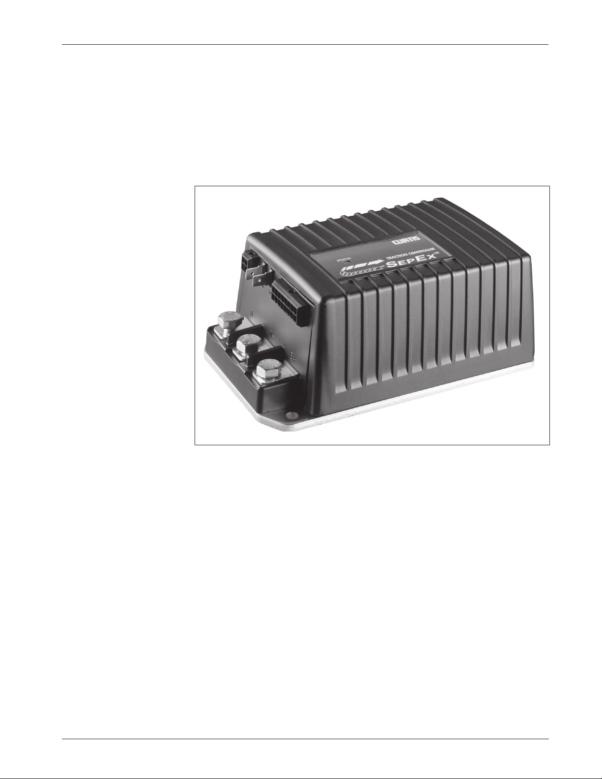
Curtis 1243 Generation 2 MultiMode™ controllers are separately excited
motor speed controllers designed for use in a variety of small industrial vehicles
and in material handling equipment. These programmable controllers are
simple to install, efficient, and cost effective, while offering more features than
the original 1243.
1
Fig. 1 Curtis 1243GEN2
MultiMode™ electronic
motor controller.
The 1243GEN2 MultiMode™ controller provides smooth precise control
of motor speed and torque. A full-bridge field control stage is combined with a
half-bridge armature power stage to provide solid state motor reversing and full
regenerative braking without additional relays or contactors.
The controller’s rugged IP53 housing and packaging are built to with-
stand shock and vibration. State-of-the-art surface mount logic board fabrication makes the 1243
GEN2 controller even more reliable than the original 1243.
The 1243GEN2 is fully programmable through the Curtis 13XX handheld
programmer. In addition to configuration flexibility, the programmer provides
diagnostic and test capability.
Page 9

Curtis 1243GEN2 Manual
2
1 — OVERVIEW
Like all Curtis motor controllers, the 1243GEN2 offers superior operator control
of the vehicle’s motor drive speed. Features include:
✓ Interlock braking with load sensor to meet required braking distance
without unnecessary harsh braking at light loads
✓ Maintenance monitor responds to preset vehicle operating hours and
drive hours as programmed by the OEM
✓ Two hourmeters—total KSI-on hours and traction hours—and the
associated maintenance timers are built into the controller
✓ BDI calculations performed within controller
✓ Estimates motor temperature based on field resistance and cuts back
maximum speed if the motor is overheated
✓ Diagnostic checks for field open and field shorted faults
✓ Supports PWM electromagnetic brake with maximum continuous
current of 2 amps
✓ Supports Type 4 throttle
✓ Active precharge of controller capacitor bank extends life of main
contactor
✓ Compatibility with Curtis 1307/1311 handheld programmers for quick
and easy testing, diagnostics, and parameter adjustment
✓ MultiMode™ allows four user-selectable vehicle operating modes
✓ Continuous armature current control, reducing arcing and brush wear
✓ Complete diagnostics through the handheld programmer, the built-in
Status LED, and the optional 840 Spyglass display
✓ Two fault outputs provide diagnostics to remotely mounted displays
✓ Regenerative braking allows shorter stopping distances, increases battery
charge, and reduces motor heating
✓ Automatic braking when throttle is reduced provides a compression
braking feel and enhances safety
✓ Brake/Drive Interlock meets ISO stopping distance requirements
✓ Ramp restraint feature provides automatic electronic braking
that restricts vehicle movement while in neutral
✓ Meets EEC fault detect requirements
✓ Linear cutback of motor drive current during overtemperature or
undervoltage
Page 10

Curtis 1243GEN2 Manual
3
✓ Linear cutback of regenerative braking current during overvoltage
✓ High pedal disable (HPD) and static return to off (SRO) interlocks
prevent vehicle runaway at startup
✓ Internal and external watchdog circuits ensure proper software operation
✓ Fully protected inputs and short-circuit protected output drivers.
Curtis Model 840 Spyglass Display [optional]
✓ 3-wire serial interface
✓ Sequences between hourmeter, BDI, and error displays
✓ Single alphanumeric, non-backlit, 8 character, 5 mm LCD display for
hourmeter, BDI, and fault messages
✓ Display updated by dedicated unidirectional serial port
✓ Available in 52 mm round case, DIN case, and as a bare board, each
with an 8-pin Molex connector; cases feature front seal to IP65 and rear
seal to IP40; shock and vibration protection to SAE J1378
✓ Operating temperature range -10°C to 70°C; models with lower
temperature ratings available for freezer applications
Familiarity with your Curtis controller will help you install and operate it
properly. We encourage you to read this manual carefully. If you have questions,
please contact the Curtis office nearest you.
1 — OVERVIEW
Page 11
Curtis 1243GEN2 Manual
4
INSTALLATION AND WIRING
MOUNTING THE CONTROLLER
The controller can be oriented in any position, but the location should be
carefully chosen to keep the controller as clean and dry as possible. If a
clean, dry mounting location cannot be found, a cover must be used to
shield the controller from water and contaminants. When selecting the
mounting position, be sure to also take into consideration (1) that access is
needed at the front of the controller to plug the programmer into its connector,
and (2) that the built-in Status LED is visible only through the view port in the
label on top of the controller.
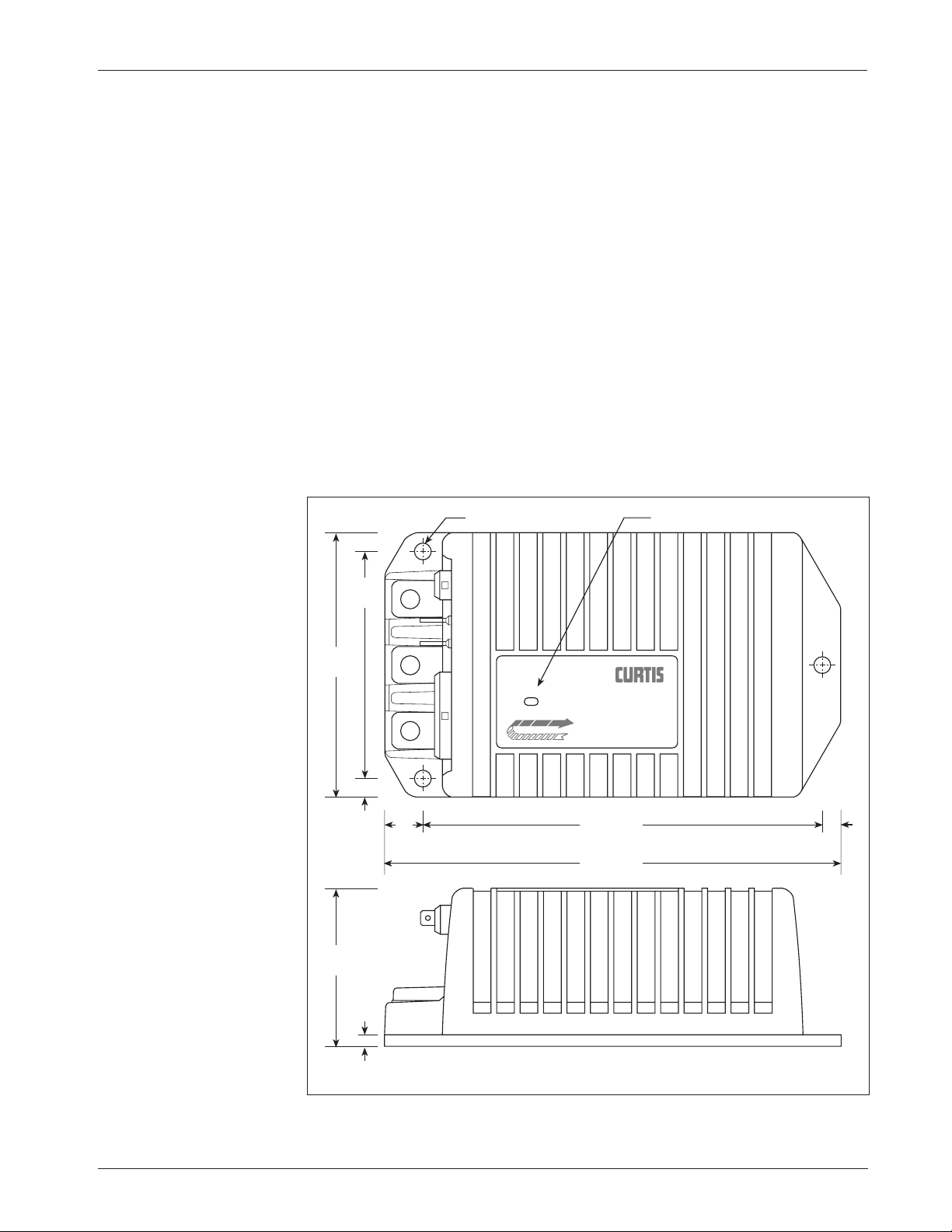
The outline and mounting hole dimensions for the 1243GEN2 controller
are shown in Figure 2. To ensure full rated power, the controller should be
fastened to a clean, flat metal surface with three 6 mm (1/4") diameter screws,
using the holes provided.
2
2 — INSTALLATION & WIRING:
Controller
Fig. 2 Mounting
dimensions, Curtis
1243
GEN2 controller.
Dimensions in millimeters (and inches)
C
L
SEPE
X
198 (7.78)
6.4 (0.25) dia., 3 plcs
68
(2.68)
114
(4.50)
173 (6.81)
17
(0.66)
7.9
(0.31)
99
(3.88)
4.8
(0.19)
7.9
(0.31)
STAT US
Status LED
TRACTION CONTROLLER
TM
Page 12

Curtis 1243GEN2 Manual
5
2 — INSTALLATION & WIRING:
Controller
The mounting surface must be at least a 300×300×3 mm (12"×12"×1/8")
aluminum plate, or its equivalent, and subjected to a minimum 3 mph airflow
to meet the specified time/current ratings. Although not usually necessary, a
thermal joint compound can be used to improve heat conduction from the
controller heatsink to the mounting surface.
You will need to take steps during the design and development of your
end product to ensure that its EMC performance complies with applicable
regulations; suggestions are presented in Appendix A.
The 1243GEN2 controller contains ESD-sensitive components. Use
appropriate precautions in connecting, disconnecting, and handling the controller. See installation suggestions in Appendix A for protecting the controller
from ESD damage.
Working on electric vehicles is potentially dangerous. You should
protect yourself against runaways, high current arcs, and outgassing from
lead acid batteries:
RUNAWAYS — Some conditions could cause the vehicle to run out of
control. Disconnect the motor or jack up the vehicle and get the drive
wheels off the ground before attempting any work on the motor control
circuitry.
HIGH CURRENT ARCS — Electric vehicle batteries can supply very high
power, and arcs can occur if they are short circuited. Always open the
battery circuit before working on the motor control circuitry. Wear safety
glasses, and use properly insulated tools to prevent shorts.
LEAD ACID BATTERIES — Charging or discharging generates hydrogen gas,
which can build up in and around the batteries. Follow the battery
manufacturer’s safety recommendations.
Wear safety glasses.
☞
C A U T I O N
Page 13
Curtis 1243GEN2 Manual
6
CONNECTIONS
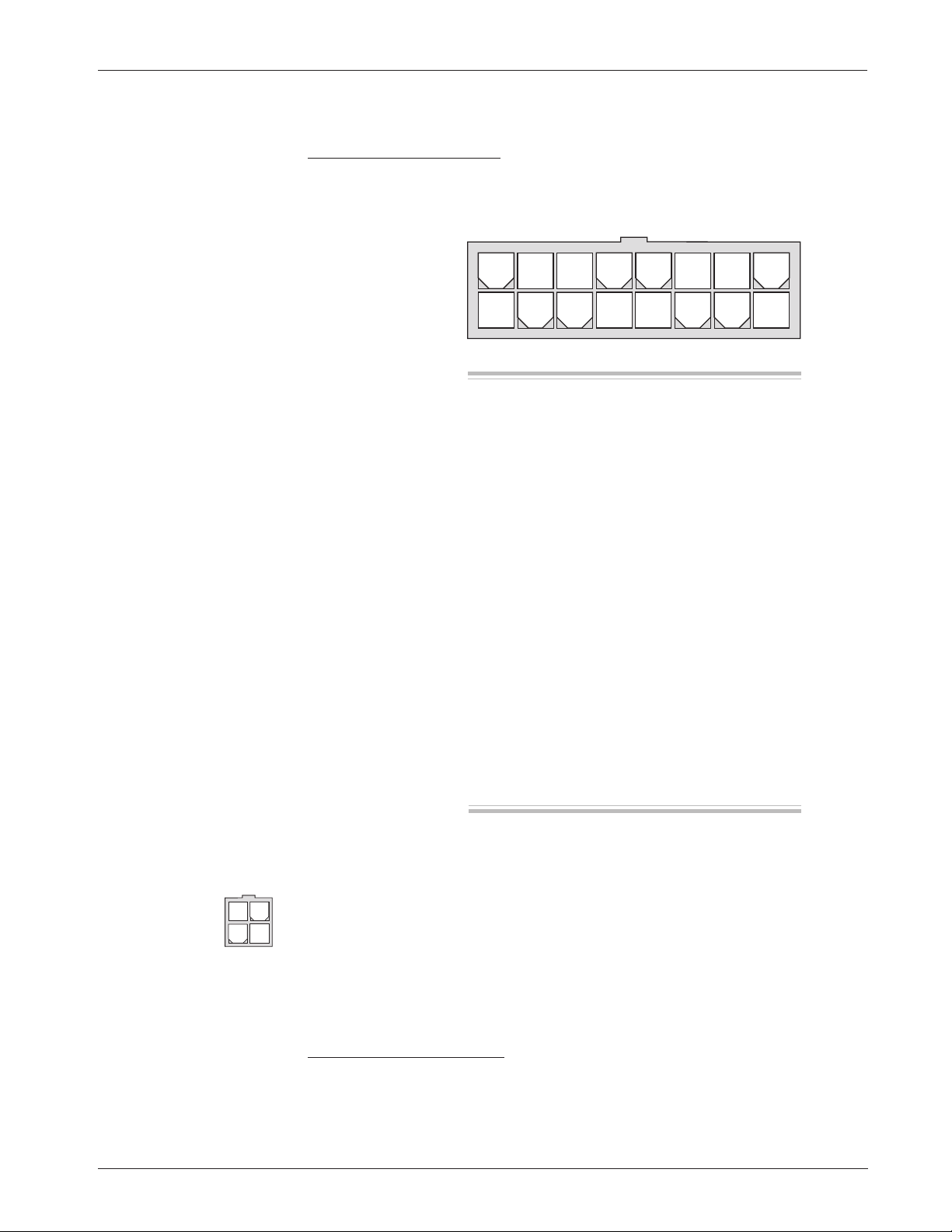
Low Current Connections
A 16-pin Molex low current connector in the controller provides the low current
logic control connections:
2 — INSTALLATION & WIRING:
Controller
The mating connector is a 16-pin Molex Mini-Fit Jr. connector p/n 39-01-2165
using type 5556 terminals.
A 4-pin low power connector is provided for the handheld programmer. A
complete 1311 programmer kit, including the appropriate connecting cable,
can be ordered from Curtis.
The 4-pin connector can also be used for the Spyglass display. The display
is unplugged when the programmer is used.
High Current Connections
Three tin-plated solid copper bus bars are provided for high current connections
to the battery (B+ and B-) and the motor armature (M-). Cables are fastened to
the bus bars by M8 bolts. The 1243GEN2 case provides the capture nuts required
Pin 1 load sensor input [optional]
Pin 2 Fault 1 output / pump input
Pin 3 Fault 2 output
Pin 4 main contactor driver output
Pin 5 throttle: 3-wire pot high
Pin 6 throttle: 0–5V; pot wiper
Pin 7 throttle: pot low
Pin 8 auxiliary driver output (typically
used for an electromagnetic brake)
Pin 9 Mode Select 2 input
Pin 10 emerg. reverse check output [optional]
Pin 11 reverse input
Pin 12 forward input
Pin 13 emergency reverse input
Pin 14 Mode Select 1 input
Pin 15 interlock input
Pin 16 keyswitch input (KSI)
8 7 6 5 4 3 2 1
16 15 14 13 12 11 10 9
Pin 1 receive data (+5V)
Pin 2 ground (B-)
Pin 3 transmit data (+5V)
Pin 4 +15V supply (100mA)
34
12
Page 14
Curtis 1243GEN2 Manual
7
2 — INSTALLATION & WIRING:
Controller
for the M8 bolts. The maximum bolt insertion depth below the surface of the
bus bar is 1.3 cm (1/2"). Bolt shafts exceeding this length may damage the controller.
The torque applied to the bolts should not exceed 16.3 N·m (12 ft-lbs).
Two 1/4" quick connect terminals (S1 and S2) are provided for the
connections to the motor field winding.
WIRING: Standard Configuration
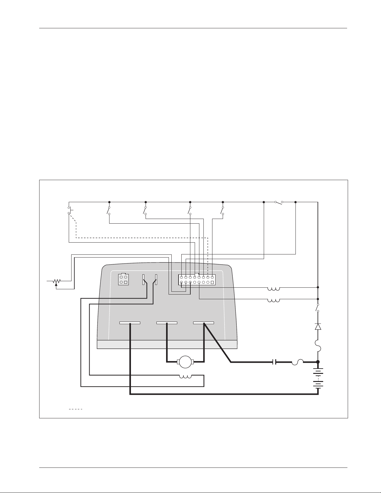
Figure 3 shows the typical wiring configuration for most applications. For
walkie applications the interlock switch is typically activated by the tiller, and
an emergency reverse switch on the tiller handle provides the emergency reverse
signal.
For rider applications the interlock switch is typically a seat switch or a
foot switch, and there is no emergency reverse.
Fig. 3 Standard wiring configuration, Curtis 1243GEN2 controller.
S1 S2
B- M- B+
INTERLOCK
5 kΩ POT
THROTTLE
(TYPICAL)
EMERGENCY
REVERSE
emergency reverse wiring check (optional)
FORWARD
MAIN
CONTACTOR
COIL
POLARITY
PROTECTION
DIODE
REVERSE
MODE
SELECT
1
MODE
SELECT
2
ELECTRO-
MAGNETIC
BRAKE
KEY
SWITCH
POWER
FUSE
A
MAIN
CONTACTOR
B+
B-
A2 A1
S2 S1
CONTROL
FUSE
1
9
8
16
Page 15

Curtis 1243GEN2 Manual
8
2 — INSTALLATION & WIRING:
Controller
Standard Power Wiring
Motor armature wiring is straightforward, with the armature’s A1 connection
going to the controller’s B+ bus bar and the armature’s A2 connection going to
the controller’s M- bus bar.
The motor’s field connections (S1 and S2) are less obvious. The direction
of vehicle travel with the forward direction selected will depend on how the
motor’s S1 and S2 connections are made to the controller’s two field terminals
(S1 and S2) and how the motor shaft is connected to the drive wheels through
the vehicle’s drive train.
CAUTION:
The polarity of the S1 and S2 connections
will affect the operation of the emergency reverse feature. The forward and
reverse switches and the S1 and S2 connections must be configured so that the
vehicle drives away from the operator when the emergency reverse button is
pressed.
Standard Control Wiring
Wiring for the input switches and contactors is shown in Figure 3; the pins are
identified on page 6. In the standard wiring configuration, the auxiliary driver
at Pin 8 is used to drive an electromagnetic brake.
The main contactor coil must be wired directly to the controller as shown
in Figure 3. The controller checks for welded or missing contactor faults and
uses the main contactor coil driver output to disconnect the battery from the
controller and motor when specific faults are present. If the main contactor coil
is not wired to Pin 4, the controller will not be able to open the main contactor
in serious fault conditions and the system will therefore not meet EEC safety
requirements.
☞
C A U T I O N
Page 16

Curtis 1243GEN2 Manual
9
2 — INSTALLATION & WIRING:
Throttle
WIRING: Throttle
Wiring for various throttles is described below. They are categorized as Type 1,
2, 3, and 4 throttles in the program menu of the handheld programmer. Note:
In the text, throttles are identified by their nominal range and not by their actual
active range.
Appropriate throttles for use with the 1243GEN2 controller include twowire 5kΩ–0 throttles (“Type 1”); 0–5V throttles, current source throttles,
three-wire potentiometer throttles, and electronic throttles wired for singleended operation (all “Type 2”); two-wire 0–5kΩ throttles (“Type 3”), and
0–5V and three-wire potentiometer throttles wired for wigwag operation
(“Type 4”). The operating specifications for these throttle types are summarized
in Table 1. Refer to Section 3: Programmable Parameters, for information on
the effects of the Throttle Deadband and Throttle Max parameters on the
minimum and maximum throttle thresholds.
If the throttle you are planning to use is not covered, contact the Curtis
office nearest you.
Table 1 THROTTLE WIPER INPUT THRESHOLD VALUES
MAXIMUM THROTTLE HPD THROTTLE MINIMUM
THROTTLE THROTTLE DEADBAND (25% throttle MAX THROTTLE
TYPE PARAMETER FAULT (0% speed request) active range) (100% modulation) FAULT
1 (5kΩ–0) Wiper Voltage 5.00 V 3.80 V 2.70 V 0.20 V 0.06 V
Wiper Resistance 7.50 kΩ 5.50 kΩ 3.85 kΩ 0 kΩ —
2 (0–5V) Wiper Voltage 0.06 V 0.20 V 1.50 V 5.00 V 5.80 V
Wiper Resistance — — — — —
3 (0–5kΩ) Wiper Voltage 0.06 V 0.20 V 1.30 V 3.80 V 5.00 V
Wiper Resistance — 0 kΩ 1.65 kΩ 5.50 kΩ 7.50 kΩ
4 (0–5V) Wiper Voltage 0.50 V 2.50 V (fwd) * 3.10 V (fwd) 4.40 V (fwd) 4.50 V
2.50 V (rev) * 1.90 V (rev) 0.60 V (rev)
Wiper Resistance — — — — —
Notes: The Throttle Deadband and Throttle Max thresholds are valid for nominal 5kΩ
potentiometers or 5V sources with the default Throttle Deadband and Throttle
Max parameter settings of 0% and 100% respectively. These threshold values
will change with variations in the Throttle Deadband and Throttle Max parameter settings
.
The HPD thresholds are 25% of the active throttle range and therefore
dependent on the programmed Throttle Deadband and Throttle Max settings
(which define the active range).
The wiper voltage is measured with respect to B-.
The wiper resistance is measured from pot low to pot wiper. The potentiometer
must be disconnected from the controller when making this measurement.
* With a 0% Throttle Deadband setting, there is no neutral point on
a Type 4 throttle. A Throttle Deadband setting of at least 8% is
recommended for Type 4 throttles.
Page 17
Curtis 1243GEN2 Manual
10
2 — INSTALLATION & WIRING:
Throttle
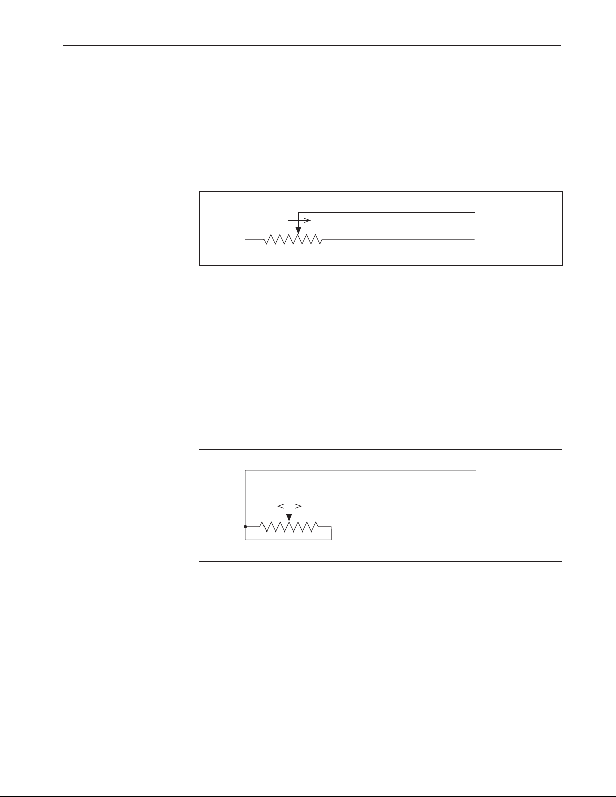
5kΩ–0 Throttle (“Type 1”)
The 5kΩ–0 throttle (called a “Type 1” throttle in the programming menu of the
13XX programmer) is a 2-wire resistive throttle that connects between the Pot
Wiper and Pot Low pins (Pins 6 and 7), as shown in Figure 4. It doesn’t matter
which wire goes on which pin. For Type 1 throttles, zero speed corresponds to
5 kΩ measured between the two pins and full speed corresponds to 0 Ω. (Note:
This wiring is also shown in the standard wiring diagram, Figure 3.)
Fig. 4 Wiring for 5k
Ω
–0
throttle (“Type 1”).
In addition to accommodating the basic 5kΩ–0 throttle, the Type 1
throttle is the easiest with which to implement a wigwag-style throttle.
Using a 20kΩ potentiometer wired as shown in Figure 5, the pot wiper can
be set such that the controller has 5 kΩ between Pins 6 and 7 when the
throttle is in the neutral position. The throttle mechanism can then be
designed such that rotating it either forward or back decreases the resistance
between Pins 6 and 7, which increases the controller output. The throttle
mechanism must provide signals to the controller’s forward and reverse
inputs independent of the throttle pot resistance. The controller will not
sense direction from the pot resistance.
Fig. 5 Wiring for 20k
Ω
potentiometer used as a
wigwag-style throttle
(“Type 1”).
20 kΩ
FASTERFASTER
Pot Wiper input (Pin 6)
Pot Low input (Pin 7)
Broken wire protection is provided by the controller sensing the current
flow from the wiper input through the potentiometer and into the Pot Low pin.
If the Pot Low input current falls below 0.65 mA or its voltage below 0.06 V, a
throttle fault is generated and the controller is disabled. Note: The Pot Low pin
(Pin 7) must not be tied to ground (B-).
5kΩ–0
Pot Low input (Pin 7)
Pot Wiper input (Pin 6)
FASTER
Page 18
Curtis 1243GEN2 Manual
11
2 — INSTALLATION & WIRING:
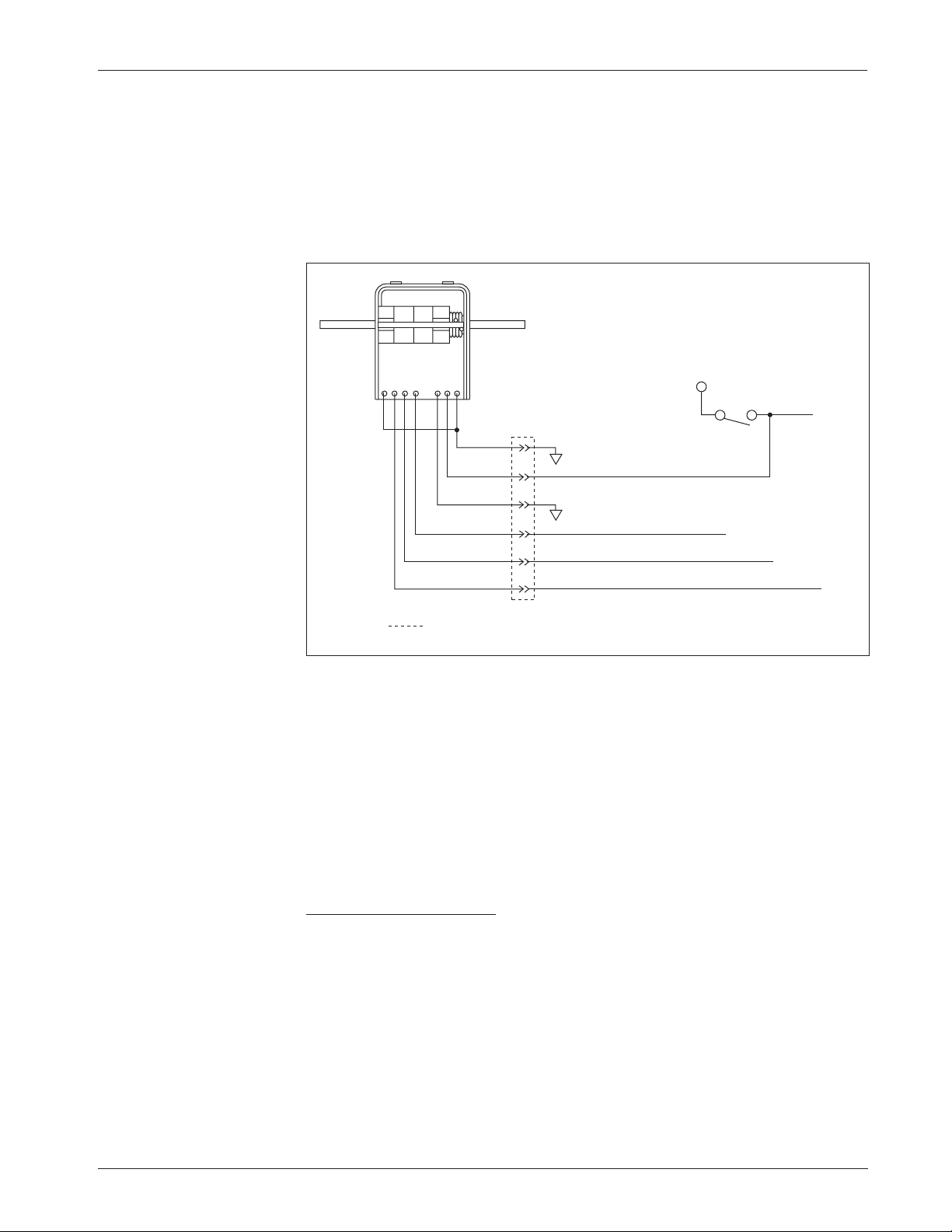
Throttle
0–5V, Current Source, 3-Wire Potentiometer,
and Electronic Throttles (“Type 2”)
With these throttles (“Type 2” in the programming menu) the controller looks
for a voltage signal at the wiper input (Pin 6). Zero speed will correspond to 0 V
and full speed to 5 V (measurements made relative to B-). A voltage source,
current source, 3-wire potentiometer, or electronic throttle can be used with this
throttle type. The wiring for each is slightly different and each has varying levels
of throttle fault detection associated with it.
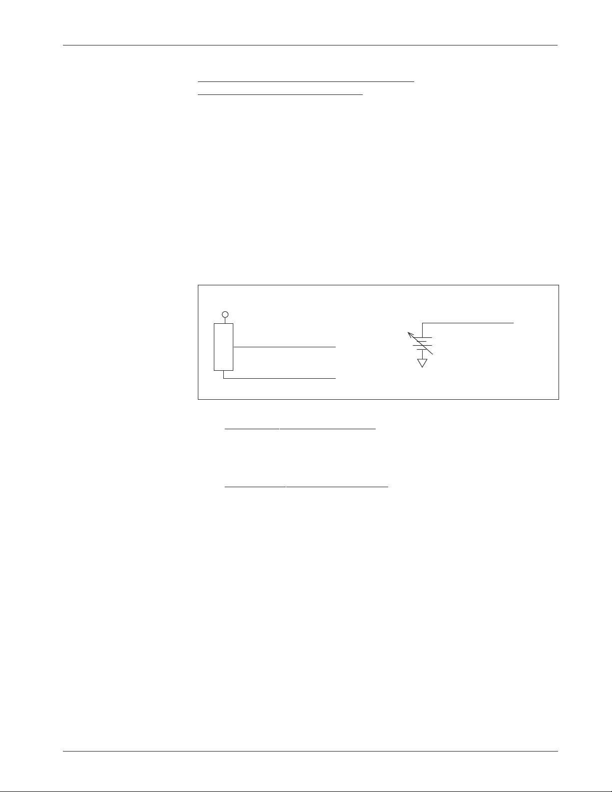
0–5V Throttle
Two ways of wiring the 0–5V throttle are shown in Figure 6. The active range
for this throttle is from 0.2 V (at 0% Throttle Deadband) to 5.0 V (at 100%
Throttle Max), measured relative to B-.
Fig. 6 Wiring for
0–5V throttles (“Type 2”).
Sensor-referenced 0–5V throttles must provide a Pot Low current greater
than 0.65 mA to prevent shutdown due to pot faults. It is recommended that
the maximum Pot Low current be limited to 55 mA to prevent damage to the
Pot Low circuitry.
Ground-referenced 0–5V throttles require setting the Pot Low Fault
parameter (see Section 3, page 38) to Off; otherwise the controller will register
a throttle fault and will shut down. For ground-referenced 0–5V throttles, the
controller will detect open breaks in the wiper input but cannot provide full
throttle fault protection. Also, the controller recognizes the voltage between the
wiper input and B- as the applied throttle voltage and not the voltage from the
voltage source relative to the Pot Low input.
For either throttle input, if the 0–5V throttle input (Pin 6) exceeds 5.5 V
relative to B-, the controller will register a fault and shut down.
+
-
B-
+
SENSOR GROUND
SENSOR OUTPUT (0–5V)
S E N S O R
Pot Low input (Pin 7)
0–5V input (Pin 6)
0–5V input (Pin 6)
Pot Low Fault setting = OFF
☞
Sensor-referenced 0–5V source Ground-referenced 0–5V source
Page 19
Curtis 1243GEN2 Manual
12
2 — INSTALLATION & WIRING:
Throttle
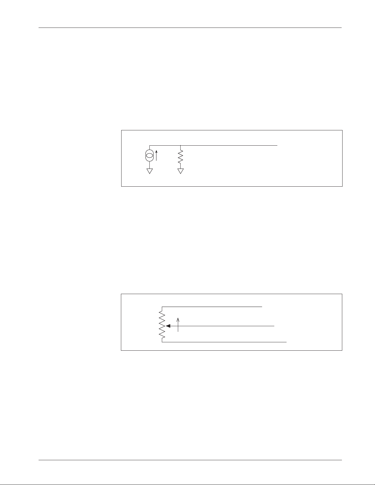
Current Sources As Throttles
A current source can also be used as a throttle input, wired as shown in Figure 7.
A resistor, R
throttle
, must be used to convert the current source value to a voltage.
The resistor should be sized to provide a 0–5V signal variation over the full
current range.
The Pot Low Fault parameter (see Section 3, page 38) must be set to Off;
otherwise the controller will register a throttle fault and will shut down. It is the
responsibility of the vehicle manufacturer to provide appropriate throttle fault
detection in applications using a current source as a throttle.
Fig. 8 Wiring for 3-wire
potentiometer throttle
(“Type 2”).
1kΩ–10kΩ
Pot Wiper input (Pin 6)
Pot Low input (Pin 7)
Pot High output (Pin 5)
FASTER
Fig. 7 Wiring for current
source throttle (“Type 2”).
3-Wire Potentiometer (1kΩ–10kΩ) Throttle
A 3-wire pot with a total resistance value anywhere between 1 kΩ and 10 kΩ can
be used, wired as shown in Figure 8. The pot is used in its voltage divider mode,
with the voltage source and return being provided by the 1243GEN2 controller.
Pot High (Pin 5) provides a current limited 5V source to the pot, and Pot Low
(Pin 7) provides the return path. If a 3-wire pot is used and the Pot Low Fault
parameter (see Section 3, page 38) is set to On, the controller will provide full
throttle fault protection in accordance with EEC requirements. Note: the Pot
Low pin (Pin 7) must not be tied to ground (B-).
R
throttle
I
source
B-B-
0–5V input (Pin 6)
Pot Low Fault setting = OFF
☞
Page 20
Curtis 1243GEN2 Manual
13
2 — INSTALLATION & WIRING:
Throttle
Curtis ET-XXX Electronic Throttle
The Curtis ET-XXX provides a 0–5V throttle and forward/reverse inputs for the
1243GEN2 controller. Wiring for the ET-XXX is shown in Figure 9. When an
electronic throttle is used, the Pot Low Fault parameter (see Section 3, page 38)
must be set to Off; otherwise the controller will register a throttle fault and will
shut down.
There is no fault detection built into the ET-XXX, and the controller will
detect only open wiper faults. It is the responsibility of the vehicle manufacturer
to provide any additional throttle fault detection necessary.
The ET-XXX can be integrated into a control head to provide wigwagstyle throttle control. Alternatively, a complete control head assembly is available from Curtis. This control head assembly—the CH series—combines the
ET-XXX throttle with a variety of standard control head switch functions for
use in walkie and lift truck applications.
0–5kΩ Throttle (“Type 3”)
The 0–5kΩ throttle (“Type 3” in the programming menu) is a 2-wire resistive
throttle that connects between the Pot Wiper and Pot Low pins (Pins 6 and 7)
as shown in Figure 10. Zero speed corresponds to 0 Ω measured between the two
pins and full speed corresponds to 5 kΩ. This throttle type is not appropriate
for use in wigwag-style applications.
Broken wire protection is provided by the controller sensing the current
flow from the wiper input through the potentiometer and into the Pot Low pin.
If the Pot Low input current falls below 0.65 mA or its voltage below 0.06 V,
Fig. 9 Wiring for Curtis
ET-XXX electronic throttle
(“Type 2”).
GREEN
ORANGE
BLACK
BLACK/WHITE
WHITE
WHT/BRN
B+
KEYSWITCH
connector
WHT/GRN
Reverse input (Pin 11)
KSI (Pin 16)
0–5V input (Pin 6)
Forward input (Pin 12)
Pot Low Fault setting = OFF
☞
B-
B-
Page 21

Curtis 1243GEN2 Manual
14
2 — INSTALLATION & WIRING:
Throttle
Fig. 10 Wiring for
0–5k
Ω
throttle
(“Type 3”).
a throttle fault is generated and the controller is disabled. Note: The Pot Low
pin (Pin 7) must not be tied to ground (B-).
Wigwag-Style 0–5V Voltage Source and 3-Wire Pot Throttle (“Type 4”)
These throttles (“Type 4” in the programming menu) operate in true wigwag
style. No signals to the controller’s forward and reverse inputs are required; the
action is determined by the wiper input value. The interface to the controller for
Type 4 devices is similar to that for Type 2 devices. The neutral point will be with
the wiper at 2.5 V, measured between Pin 6 and B-.
The controller will provide increasing forward speed as its wiper input
value (Pin 6) is increased, with maximum forward speed reached at 4.5 V. The
controller will provide increasing reverse speed as the wiper input value is
decreased, with maximum reverse speed reached at 0.5 V. The minimum and
maximum wiper voltage must not exceed the 0.5V and 4.5V fault limits.
When a 3-wire pot is used and the Pot Low Fault parameter (see Section 3,
page 36) is set to On, the controller provides full fault protection for Type 4
traction throttles. Any potentiometer value between 1 kΩ and 10 kΩ is supported. When a voltage throttle is used, it is the responsibility of the OEM to
provide appropriate throttle fault detection.
Note: If your Type 4 throttle has an internal neutral switch, this internal
neutral switch should be wired to the forward switch input (Pin 12). The
controller will behave as though no throttle is requested when the neutral
switch is high, and will use the throttle value when the neutral switch is low.
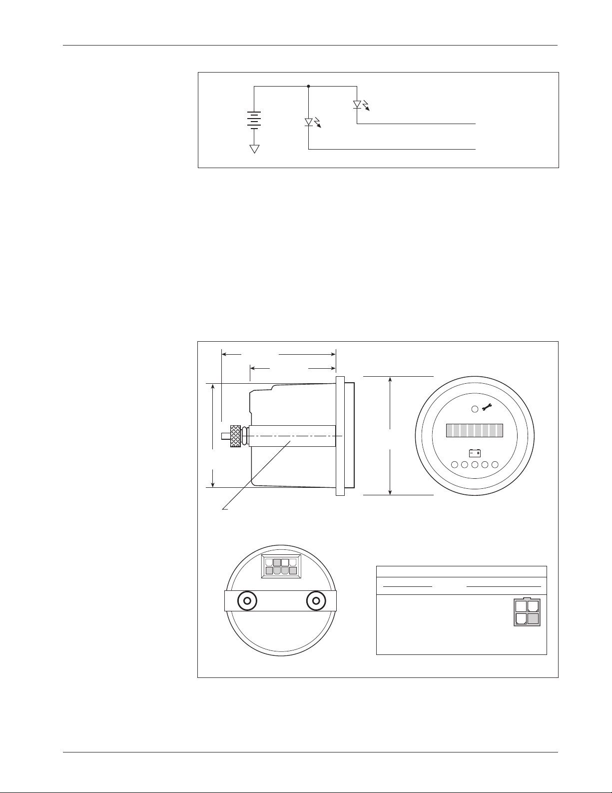
WIRING: Fault Outputs
The 1243GEN2 has two fault signal outputs (Pins 2 and 3), which can be used
to provide diagnostic information to a display panel. These current-sinking
outputs can drive LEDs or other loads requiring less than 10 mA. Since these
outputs are intended to drive LEDs, each contains a dropping resistor; as a
result, these outputs will not pull down to B-. Wiring is shown in Figure 11.
The Fault 1 and Fault 2 outputs can be programmed to display fault
information in either of two formats: Fault Code format or Fault Category
format (see Section 3, page 51).
Alternatively, Pin 2 can be used to provide a pump input signal (see pump
meter parameter, Section 3, page 48); Pin 3 can be used to interface an external
auxiliary enable circuit (see BDI lockout parameter, Section 3, page 51).
0–5kΩ
Pot Low input (Pin 7)
Pot Wiper input (Pin 6)
FASTER
Page 22
Curtis 1243GEN2 Manual
15
2 — INSTALLATION & WIRING:
Spyglass Display
Fig. 11 Wiring for fault
outputs, when used to drive
LEDs. Alternatively, Pin 2
can be used for a pump
meter input, and Pin 3 can
be used to interface an
external enable circuit.
B-
+
-
Fault 1 output (Pin 2)
Fault 2 output (Pin 3)
WIRING: Spyglass Display
The Curtis 840 Spyglass features an 8-character LCD display that sequences
between hourmeter, BDI %, and fault messages. Depending on the model,
either three or six indicator LEDs are also located on the face of the gauge. See
Section 7 (Diagnostics and Troubleshooting) for more information on the
Spyglass displays.
The mating 8-pin connector is Molex 39-01-2085, with 39-00-0039
(18–24 AWG) pins.
Fig. 12 Wiring guide and
mounting dimensions for
Curtis Spyglass (6-LED
model shown; dimensions
and wiring are identical for
the 3-LED model).
SPYGLASS 1243·GEN·2 CONTROLLER
PIN # FUNCTION PIN #
1–4 N.C. –
5 +12V, +15V 4
6 receive data 3
7 N.C. –
8 ground (B+) 2
58
(2.25)
44 (1.75)
8
58 (2.25)
52
(2.0)
“U” clamp for
up to 6 (0.25)
panel thickness
5
4 1
WIRING GUIDE
34
12
0 1
Dimensions in millimeters (and inches)
Page 23

Curtis 1243GEN2 Manual
16
2 — INSTALLATION & WIRING:
Emerg. Reverse and Aux Driver
☞
C A U T I O N
WIRING: Emergency Reverse
To implement the emergency reverse feature, Pin 13 (the emergency reverse
input) must be connected to battery voltage as shown in the standard wiring
diagram, Figure 3.
The controller provides maximum braking torque as soon as the emergency reverse switch is closed. The vehicle will then be automatically driven in
the reverse direction at the programmed emergency reverse current limit until
the emergency reverse switch is released.
CAUTION:
The polarity of the S1 and S2 connections will affect the
operation of the emergency reverse feature. The forward and reverse switches
and the S1 and S2 connections must be configured so that the vehicle drives
away from the operator when the emergency reverse button is pressed.
WIRING: Emergency Reverse Check
An optional wire connected directly to the emergency reverse switch provides for
broken wire detection when that feature is programmed On (see Section 3,
page 43). The emergency reverse check output wire periodically pulses the
emergency reverse circuit to check for continuity in the wiring. If there is no
continuity, the controller output is inhibited until the wiring fault is corrected.
The emergency reverse check wire is connected to Pin 10 as shown by the
dotted line in the standard wiring diagram, Figure 3. If the option is selected
and the check wire is not connected, the vehicle will not operate. If the option
is not selected and the check wire is connected, no harm will occur—but
continuity will not be checked.
WIRING: Auxiliary Driver
The 1243GEN2 provides an auxiliary driver at Pin 8. This low side driver is
designed to energize an electromagnetic brake coil, as shown in the standard
wiring diagram (Figure 3). The output is rated at 2 amps and is overcurrent
protected. A coil suppression diode is provided internally to protect the driver
from inductive spikes generated at turn-off. The recommended wiring is shown
in the standard wiring diagram, Figure 3. The contactor coil or driver load
should not be connected directly to B+, which would cause the controller to be
always biased On via a path through the coil suppression diode to the KSI input.
Although it is typically used to drive an EM brake, the auxiliary driver can
be used to drive a pump contactor or hydraulic steering assist in applications
not requiring an EM brake.
Note: Because the auxiliary driver is typically used for an EM brake, the
programmable parameters related to this driver are described in the electromagnetic brake parameter group; see page 28.
Page 24

Curtis 1243GEN2 Manual
17
CONTACTOR, SWITCHES, and OTHER HARDWARE
Main Contactor
A main contactor should be used with any 1243GEN2 controller; otherwise the
controller’s fault detects will not be able to fully protect the controller and motor
drive system from damage in a fault condition. The main contactor allows the
controller and motor to be disconnected from the battery. This provides a
significant safety feature in that the battery power can be removed from the drive
system if a controller or wiring fault results in full battery power being applied
to the motor. If the Contactor Diagnostics parameter (see Section 3, page 40)
is On, the controller will conduct a missing contactor check and a welded
contactor check each time the main contactor is requested to close and will not
proceed with the request if a fault is found.
A single-pole, single-throw (SPST) contactor with silver-alloy contacts,
such as an Albright SW80 or SW180—available from Curtis—is recommended for use as the main contactor. The contactor coils should be specified
with a continuous rating at the nominal battery pack voltage.
The main contactor coil driver output (Pin 4) is rated at 2 amps, is overcurrent protected, and is checked for open coil faults. A built-in coil suppression diode is connected between the main contactor coil driver output and the
keyswitch input. This protects the main contactor coil driver from failure due
to inductive voltage kickback spikes when the contactor is turned off.
Keyswitch and Interlock Switch
The vehicle should have a master on/off switch to turn the system off when not
in use. The keyswitch input provides logic power for the controller.
The interlock switch—which is typically implemented as a tiller switch,
deadman footswitch, or seatswitch—provides a safety interlock for the system.
The keyswitch and interlock switch provide current to drive the main
contactor coil and all other output driver loads as well as the controller’s internal
logic circuitry and must be rated to carry these currents.
Forward, Reverse, Mode Select, and Emergency Reverse Switches
These input switches can be any type of single-pole, single-throw (SPST) switch
capable of switching the battery voltage at 10 mA. Typically the emergency
reverse switch is a momentary switch, active only while it is being pressed.
Reverse Polarity Protection Diode
For reverse polarity protection, a diode should be added in series between the
battery and KSI. This diode will prohibit main contactor operation and current
flow if the battery pack is accidentally wired with the B+ and B- terminals
exchanged. It should be sized appropriately for the maximum contactor coil and
fault diode currents required from the control circuit. The reverse polarity
protection diode should be wired as shown in the standard wiring diagram,
Figure 3 (page 7).
2 — INSTALLATION & WIRING:
Main Contactor & Switches, etc.
Page 25

Curtis 1243GEN2 Manual
18
Circuitry Protection Devices
To protect the control circuitry from accidental shorts, a low current fuse
(appropriate for the maximum current draw) should be connected in series
between the battery and KSI. Additionally, a high current fuse should be wired
in series with the main contactor to protect the motor, controller, and batteries
from accidental shorts in the power system. The appropriate fuse for each
application should be selected with the help of a reputable fuse manufacturer or
dealer. The standard wiring diagram, Figure 3, shows the recommended location
for each fuse.
Mode Select Switch Operation
The two mode select switches (Mode Select 1 and Mode Select 2) together define
the four operating modes. The switch combinations are shown in Table 2.
Table 2 MODE SELECTION
MODE MODE
OPERATING MODE SELECT SELECT
SWITCH 1 SWITCH 2
MultiMode™ 1 OPEN OPEN
MultiMode™ 2 CLOSED OPEN
MultiMode™ 3 OPEN CLOSED
MultiMode™ 4 CLOSED CLOSED
Load Sensor [optional]
The 1243GEN2 provides a load sensor input at Pin 1. The controller can be
programmed to vary the strength of regen braking depending on the load sensor
input. The load sensor, if one is used, should be sized to handle your application’s
maximum expected load without exceeding 5 V.
2 — INSTALLATION & WIRING:
Switches, etc.
Page 26

Curtis 1243GEN2 Manual
19
3 — PROGRAMMABLE PARAMETERS
PROGRAMMABLE PARAMETERS
The 1243GEN2 controller has a number of parameters that can be programmed
using a Curtis handheld programmer. These programmable parameters allow
the vehicle’s performance characteristics to be customized to fit the needs of
individual vehicles or vehicle applications.
The OEM can specify the default value for each parameter and can also
designate whether a parameter will have User or OEM access rights. Accordingly, programmers are available in User and OEM versions. The User programmer can adjust only those parameters with User access rights, whereas the
OEM programmer can adjust all the parameters. For information about 1311
programmer operation, see Appendix B.
The MultiMode™ feature of the 1243GEN2 controller allows operation in
four distinct modes. These modes can be programmed to provide four different
sets of operating characteristics, which can be useful for operating in different
conditions, such as slow precise indoor maneuvering in Mode 1; faster, long
distance, outdoor travel in Mode 4; and application-specific special conditions
in Modes 2 and 3. Eight parameters can be configured independently in each
of the four modes:
— acceleration rate (M1–M4)
— braking current limit (M1–M4)
— braking rate (M1–M4)
— deceleration rate (M1–M4)
— drive current limit (M1–M4)
— maximum forward speed (M1–M4)
— maximum reverse speed (M1–M4)
— restraint (M1–M4).
To better describe their interrelationships, the individual parameters are
grouped into categories as follows:
Battery Parameters
Acceleration Parameters
Braking Parameters
Interlock Braking Parameters
Electromagnetic Brake Parameters
Speed Parameters
Throttle Parameters
Field Parameters
Contactor Parameters
Sequencing Fault Parameters
Emergency Reverse Parameters
Motor Protection Parameters
Hourmeter Parameters
BDI Parameters
Fault Code Parameters
3
Page 27

Curtis 1243GEN2 Manual
20
3 — PROGRAMMABLE PARAMETERS
Battery Parameter ...................... p.21
Battery Voltage
Acceleration Parameters ............ p. 21
Drive Current Limit, M1–M4
Acceleration Rate, M1–M4
Quick Start
Current Ratio
Braking Parameters ................... p.23
Braking Current Limit, M1–M4
Deceleration Rate, M1–M4
Throttle Deceleration Rate
Restraint, M1–M4
Braking Rate, M1–M4
Taper Rate
Variable Braking
Interlock Braking
Parameters ................................... p.26
Interlock Braking Rate
Max. Forward Regen
Max. Reverse Regen
Min. Forward Regen
Min. Reverse Regen
Max. Load Volts
Min. Load Volts
Electromagnetic Brake
Parameters ................................... p.28
Auxiliary Driver Type
Electromagnetic Brake PWM
Auxiliary Driver Delay
Interlock Brake Delay
Speed Parameters ....................... p.31
Max. Forward Speed, M1–M4
Max. Reverse Speed, M1–M4
Creep Speed
Load Compensation
Throttle Parameters ................... p.32
Throttle Type
Throttle Deadband
Throttle Max
Throttle Map
Pot Low Fault
Field Parameters ......................... p.38
Min. Field Current Limit
Max. Field Current Limit
Field Map Start
Field Map
Field Check
Main Contactor Parameters ..... p.40
Main Contactor Interlock
Main Contactor Open Delay
Main Contactor Diagnostics
Sequencing Fault Parameters ... p.41
Anti-Tiedown
High Pedal Disable (HPD)
Static Return to Off (SRO)
Sequencing Delay
Emergency Reverse
Parameters ................................... p.43
Emerg. Reverse Current Limit
Emerg. Reverse Check
Emerg. Reverse Direction Interlock
Motor Protection Parameters ... p. 44
Warm Speed
Motor Warm Resistance
Motor Hot Resistance
Motor Resistance Compensation
Hourmeter
Parameters
.................... p.45
Adjust Hours High
Adjust Hours Middle
Adjust Hours Low
Set Total Hours
Set Traction Hours
Total Service Hours
Traction Service Hours
Total Disable Hours
Traction Disable Hours
Traction Fault Speed
Service Total
Service Traction
Hourmeter Type
Pump Meter
BDI Parameters ........... p. 49
Full Voltage
Empty Voltage
Reset Voltage
Battery Adjust
BDI Disable
BDI Limit Speed
Fault Code
Parameters .................... p. 51
Fault Code
BDI Lockout
Individual parameters are described in the following text in
the order they are listed on this page. They are listed by the
abbreviated names that are displayed in the programmer’s
Program Menu. Not all of these parameters are displayed
on all controllers; the list for any given controller depends
on its specifications.
The programmer displays the parameters in a different
order. For a list of the individual parameters in the order in
which they appear in the Program Menu, see Section 6:
Programmer Menus.
☞
Page 28

Curtis 1243GEN2 Manual
21
3 — PROGRAMMABLE PARAMETERS:
Battery & Acceleration Parameters
VOLTAGE
The battery voltage parameter sets the overvoltage and undervoltage protection
thresholds for the controller and battery. Overvoltage protection cuts back
regenerative braking to prevent damage to batteries and other electrical system
components due to overvoltage; undervoltage protection prevents systems from
operating at voltages below their design thresholds. The battery voltage parameter can be set at 2 or 3, and should always be set to the system’s nominal battery
pack voltage:
NOMINAL
SETTING BATTERY PACK VOLTAGE
2 24V
3 36V
M1–M4, DRIVE C/L
The drive current limit parameter allows adjustment of the maximum current
the controller will supply to the motor during drive operation. This parameter
can be limited to reduce the maximum torque applied to the drive system by the
motor in any reduced performance mode. The drive current limit is adjustable
from 50 amps up to the controller’s full rated armature current. (The full rated
current depends on the controller model; see specifications in Table D-1.)
The drive current limit is tuned as part of the vehicle performance adjustment process (Section 5).
M1–M4, ACCEL RATE
The acceleration rate defines the time it takes the controller to accelerate from
0% drive output to 100% drive output. A larger value represents a longer
acceleration time and a gentler start. Fast starts can be achieved by reducing the
acceleration time, i.e., by adjusting the accel rate to a smaller value. The
acceleration rate is adjustable from 0.1 to 3.0 seconds.
The acceleration rate is tuned as part of the vehicle performance adjustment process (Section 5).
QUICK START
Upon receiving a sudden high throttle demand from neutral, the quick start
function causes the controller to momentarily exceed its normal acceleration
rate, in order to overcome vehicle inertia. The quick start algorithm is applied
each time the throttle passes through neutral and the controller is not in braking
Battery Parameter
Acceleration Parameters
Page 29

Curtis 1243GEN2 Manual
22
3 — PROGRAMMABLE PARAMETERS:
Braking Parameters
mode. If the controller is in braking mode, the quick start function is disabled,
allowing normal braking to occur. Quick start is adjustable from 0 to 10.
Increasing the value will “liven” the vehicle’s acceleration response to fast throttle
movements.
The quick start parameter is tuned as part of the vehicle performance
adjustment process (Section 5).
NOTE: Quick start is not a MultiMode™ parameter, and its value will
therefore affect all four operating modes.
CURRENT RATIO
The current ratio parameter defines how much of the programmed drive
current will be available to the motor at reduced throttle requests. The current
ratio parameter can be set to 1, 2, 3, or 4. These settings correspond to the
following ratios:
SETTING RATIO
1 1 : 1
2 2 : 1
3 4 : 1
4 8 : 1
For example, with the current ratio set at 1 with 20% throttle requested, 20%
of the battery voltage and 20% of the drive current will be allowed to flow in the
motor (assuming a 50% throttle map setting). If the current ratio is set at 2
under these same conditions, 40% of the current will be available; if it is set at
3, 80%. The controller will not allow more than the programmed drive current
to flow in the motor. If the current ratio is set at 4 with 20% throttle requested,
the controller will allow only 100% of the drive current and not 160%.
High current ratio values will allow quicker startup response and improved ramp climbing with partial throttle, but may cause too much jumpiness.
The current ratio parameter is tuned as part of the vehicle performance
adjustment process (Section 5).
Note: Current ratio is only effective in drive; it does not affect regen.
Page 30

Curtis 1243GEN2 Manual
23
3 — PROGRAMMABLE PARAMETERS:
Braking Parameters
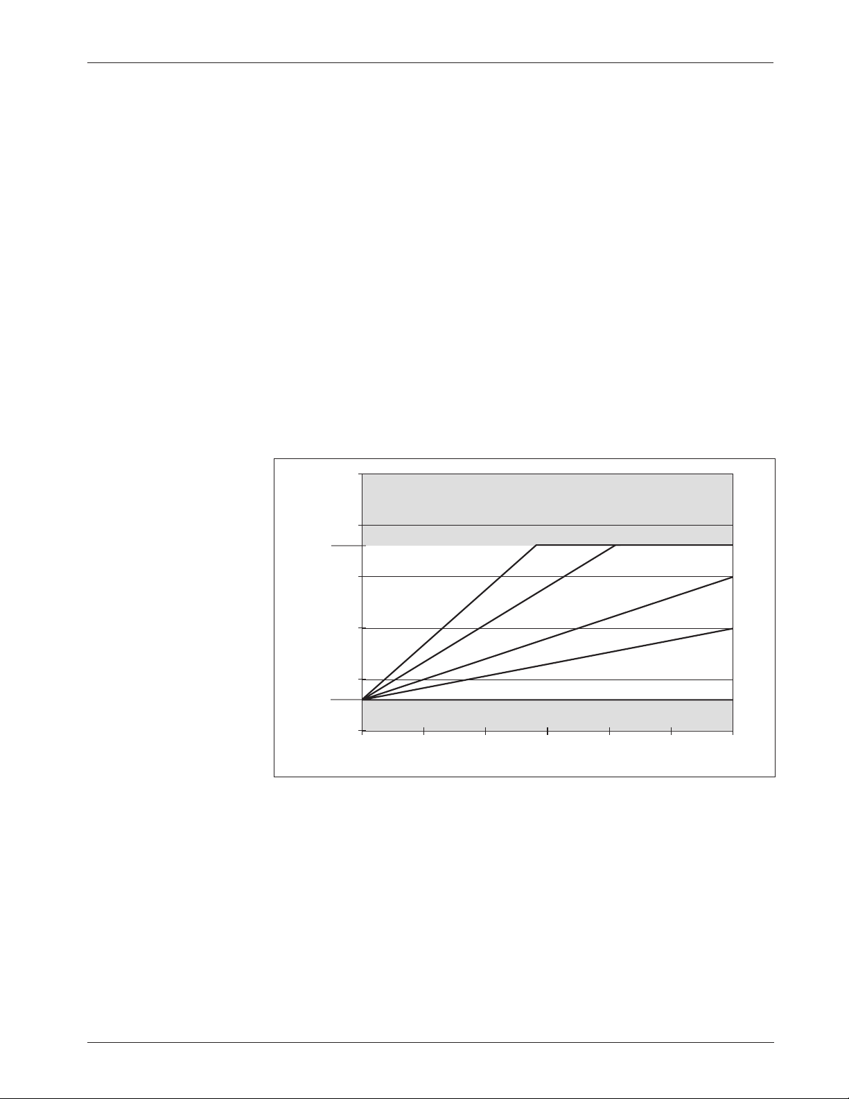
The seven Braking parameters affect the regenerative braking that is initiated when
the throttle is reduced or when the direction is reversed while the vehicle is being
driven. During regen braking, armature current flows toward the battery.
M1–M4, BRAKE C/L
The braking current limit parameter adjusts the maximum current the
controller will supply to the motor during regen braking. The braking current
limit is adjustable from 50 amps up to the controller’s full rated braking current.
(The full rated current depends on the controller model; see specifications in
Table D-1.) The braking current limit is tuned as part of the vehicle performance
adjustment process (Section 5).
M1–M4, DECEL RATE
The deceleration rate defines the time it takes the controller to reduce its
output to the new throttle request when the throttle is reduced or released. A
lower value represents a faster deceleration and thus a shorter stopping distance.
The decel rate defines the vehicle’s braking characteristic for any reduction in
throttle, including to neutral, that does not include a request for the opposite
direction. The decel rate is adjustable from 0.1 to 10.0 seconds. The decel rate
is tuned as part of the vehicle performance adjustment process (Section 5).
THROTTLE DECEL
The throttle deceleration rate parameter adjusts the rate at which the vehicle
transitions to braking when throttle is first reduced. If the throttle decel rate is
set low, deceleration is initiated abruptly. The transition is smoother if the
throttle decel rate is higher; however, setting the throttle decel parameter too
high can cause the vehicle to feel uncontrollable when the throttle is released,
as it will continue to drive for a short period. The throttle decel rate is adjustable
from 0.1 to 1.0 second, with a value of 0.3 or 0.4 working well for most vehicles.
When the armature current goes negative (i.e., at the point when positive
torque transitions to negative torque), the normal decel rate goes into effect.
M1–M4, RESTRAINT
Because the 1243
GEN2 controller is configured to provide regenerative braking,
overspeed causes the controller to create a braking current and thus limit or
“restrain” the overspeed condition. The restraint parameter determines how
strongly the controller tries to limit the vehicle speed to the existing throttle
setting. It is applicable when throttle is reduced or when the vehicle begins to
travel downhill.
Braking Parameters
Page 31
Curtis 1243GEN2 Manual
24
Fig. 13 Ramp restraint
maps for controller with
Field Min set at 3 amps,
Field Max at 18 amps, and
braking current limit at
300 amps.
BRAKING CURRENT (amperes)
FIELD CURRENT (amperes)
300250200150100500
25
20
15
10
5
0
Field Max
= 18 A
Field Min
= 3 A
Brake C/L
= 300 A
Restraint = 25 A
Restraint = 15 A
Restraint = 10 A
Restraint = 3 A
Restraint = 35 A
At zero throttle, the restraint function tries to keep the motor at zero
speed, which helps hold the vehicle from running away down ramps. The
higher the restraint parameter value, the stronger the braking force applied to
the motor and the slower the vehicle will creep down ramps. This creeping
speed depends on the restraint setting, the steepness of the ramp, and the
vehicle load weight. The restraint feature can never hold a vehicle perfectly
stationary on a ramp and is not intended to replace a mechanical or electromagnetic brake for this purpose.
The restraint parameter establishes a linear mapping of field current to
braking current, and is adjustable from the programmed minimum field (Field
Min) up to the controller’s full rated field current. As shown in Figure 13, it is
limited by the programmed maximum field (Field Max). Setting the restraint
parameter to a high value will cause strong braking, in an effort to bring the
vehicle speed down to the requested speed. Extremely high values may cause the
vehicle speed to oscillate (“hunt”) while in ramp restraint.
The restraint parameter is tuned as part of the vehicle performance
adjustment process (Section 5).
M1–M4, BRAKE RATE
The braking rate defines the time it takes the controller to increase from 0%
braking output to 100% braking output (as defined by the corresponding modespecific brake current limit) when a new direction is selected. A larger value
represents a longer time and consequently gentler braking. Faster braking is
achieved by adjusting the braking rate to a smaller value. The braking rate is
adjustable from 0.1 second to 3.0 seconds.
Note: The variable braking parameter must be programmed Off for the
braking rate parameter to apply; if variable braking is On, the braking rate will
be determined by throttle position rather than the programmed braking rate.
3 — PROGRAMMABLE PARAMETERS:
Braking Parameters
Page 32

Curtis 1243GEN2 Manual
25
TAPER RATE
The taper rate affects direction-reversal at the very end of braking, just before
the vehicle stops moving in the original direction. Low taper rate values result
in faster, more abrupt direction transitions. Higher taper rate values result in
slower and smoother direction transitions. The taper rate is adjustable from 1
to 20. The taper rate is tuned as part of the vehicle performance adjustment
process (Section 5).
VARIABLE BRAKE
The variable braking parameter defines how the controller will apply braking
force when direction-reversal braking is requested. If the variable braking
parameter is programmed On, the amount of braking current applied by the
controller will be a function of the throttle’s position when braking is requested.
With variable braking, the operator can use the throttle to control the amount
of braking force applied to a moving vehicle. Increasing throttle in the direction
opposite to the vehicle’s motion will apply increasing amounts of regen braking
current to the motor, slowing the vehicle more quickly.
If a fixed amount of braking force is preferred, the variable braking
parameter should be programmed Off. With variable braking Off, the controller applies the full braking current specified as soon as braking is requested.
3 — PROGRAMMABLE PARAMETERS:
Braking Parameters
Page 33

Curtis 1243GEN2 Manual
26
If the interlock switch opens while the vehicle is being driven, the controller uses the
motor to apply regenerative braking as soon as the programmed Sequencing Delay (see
page 42) expires. This braking—which is called interlock braking—greatly reduces
wear on the electromagnetic brake and also enables the vehicle to meet more stringent
stopping distance requirements.
As soon as interlock braking brings the motor speed to approximately zero, the
electromagnetic brake is applied. Note that for safety, the EM brake will engage after
the programmed Interlock Brake Delay (see page 28) even if interlock braking does
not bring the motor speed close to zero.
The seven Interlock Braking parameters affect the regen braking that results
when the interlock switch is opened while the vehicle is being driven.
INT BRAKE RATE
The interlock braking rate defines the time it takes the controller to increase
from 0% to 100% braking output (as determined by the max regen current
setpoints) when interlock braking is initiated. The interlock braking rate is
adjustable from 0.1 to 3.0 seconds.
MAX FWD REGEN
The maximum forward regen parameter defines the maximum regenerative
current at
maximum load while traveling in the forward direction. The max
forward regen current is adjustable from 100 amps up to the controller’s full
rated current.
If a load sensor is not used, this will be the single maximum regen current
in the forward direction.
MAX REV REGEN
The maximum reverse regen parameter defines the maximum regenerative
current at maximum load while traveling in the reverse direction. The max
reverse regen current is adjustable from 100 amps up to the controller’s full rated
current.
If a load sensor is not used, this will be the single maximum regen current
in the reverse direction.
3 — PROGRAMMABLE PARAMETERS:
Interlock Braking Parameters
Interlock Braking Parameters
Page 34

Curtis 1243GEN2 Manual
27
If your application will have widely varying loads, we recommend that you include
a load sensor (at Pin 1). The use of a load sensor can prevent unnecessarily harsh
braking at light loads, which may lock up the wheels.
MIN FWD REGEN
[applicable only with optional load sensor]
The minimum forward regen parameter defines the maximum regenerative
current at minimum load while traveling in the forward direction. The Min Fwd
Regen current is adjustable from 25 amps up to the controller’s full rated
current. The forward regen current increases linearly from Min Fwd Regen to
Max Fwd Regen as the load sensor input varies from Min Load Volts to Max
Load Volts.
Note: If the load sensor’s voltage is out of range (less than 0.2 V or greater
than 4.8 V) during interlock braking while the vehicle is driving forward, the
regen current will default to the programmed Max Fwd Regen value.
MIN REV REGEN
[applicable only with optional load sensor]
The minimum reverse regen parameter defines the maximum regenerative
current at minimum load while traveling in the reverse direction. The Min Rev
Regen current is adjustable from 25 amps up to the controller’s full rated
current. The reverse regen current increases linearly from Min Rev Regen to Max
Rev Regen as the load sensor input varies from Min Load Volts to Max Load
Volts.
Note: If the load sensor’s voltage is out of range (less than 0.2 V or greater
than 4.8 V) during interlock braking while the vehicle is driving in reverse, the
regen current will default to the programmed Max Rev Regen value.
MAX LOAD VOLTS
[applicable only with optional load sensor]
The maximum load volts parameter defines the load sensor input voltage at the
maximum load. It is adjustable from 0.2 V to 4.8 V.
MIN LOAD VOLTS
[applicable only with optional load sensor]
The minimum load volts parameter defines the load sensor input voltage at the
minimum load. It is adjustable from 0.2 V up to the programmed Max Load
Volts.
3 — PROGRAMMABLE PARAMETERS:
Interlock Braking Parameters
Page 35

Curtis 1243GEN2 Manual
28
The four Electromagnetic Brake parameters—along with the sequencing delay—
affect the behavior of the auxiliary driver at Pin 8. This driver is typically used for
an electromagnetic brake, as shown in the basic wiring diagram (Figure 3, page 7).
See Figure 14 for an illustration of the relationship between interlock braking, the
EM brake, and the sequencing, auxiliary, and interlock braking delays.
AUX TYPE
The auxiliary driver type parameter configures the low side driver at Pin 8. The
auxiliary driver can be programmed to operate in any of the configurations (i.e.,
Types 1 through 5) described in Table 3. Types 1 through 4 are various ways of
configuring the driver for an electromagnetic brake; Type 5 is a non-EM-brake
option. If no auxiliary device will be connected to Pin 8, the auxiliary driver
should be programmed to Type 0.
EM BRAKE PWM
The auxiliary driver output (at Pin 8) can be modulated if you are using an EM
brake (or other auxiliary device) whose coil voltage rating is lower than the
battery voltage. If the electromagnetic brake PWM parameter is programmed
On, the brake will pull in at 100% PWM (full current up to 3 amps) for 500
ms and then pull back to 62.5% PWM (≈2 amps max) at a frequency of about
250 Hz and continue at this level until released. If programmed Off, the
auxiliary driver output will remain steadily at 100% PWM.
AUX DELAY
The auxiliary driver delay parameter allows a delay before the electromagnetic
brake is engaged (Pin 8 driver opened) after the vehicle reaches the neutral state
(throttle in neutral, both direction switches open, motor speed approximately
zero). The Aux Delay is adjustable from 0 to 30 seconds. When set to zero, there
is no delay and the brake is engaged as soon as the vehicle reaches the neutral
state. This parameter does not apply to Aux Type 1 (see Table 3).
For Aux Type 5, the device connected to Pin 8 will be off when the Pin
8 driver is open, and on when the driver is closed. The aux delay could be used
to allow the auxiliary device to keep running for a short while after the vehicle
reaches the neutral state.
INT BRAKE DLY
The interlock brake delay parameter allows a delay before the electromagnetic
brake is engaged after the interlock switch opens; during this time, interlock
braking is in effect. The electromagnetic brake is engaged when the delay has
Electromagnetic Brake Parameters
3 — PROGRAMMABLE PARAMETERS:
Electromagnetic Brake Parameters
Page 36
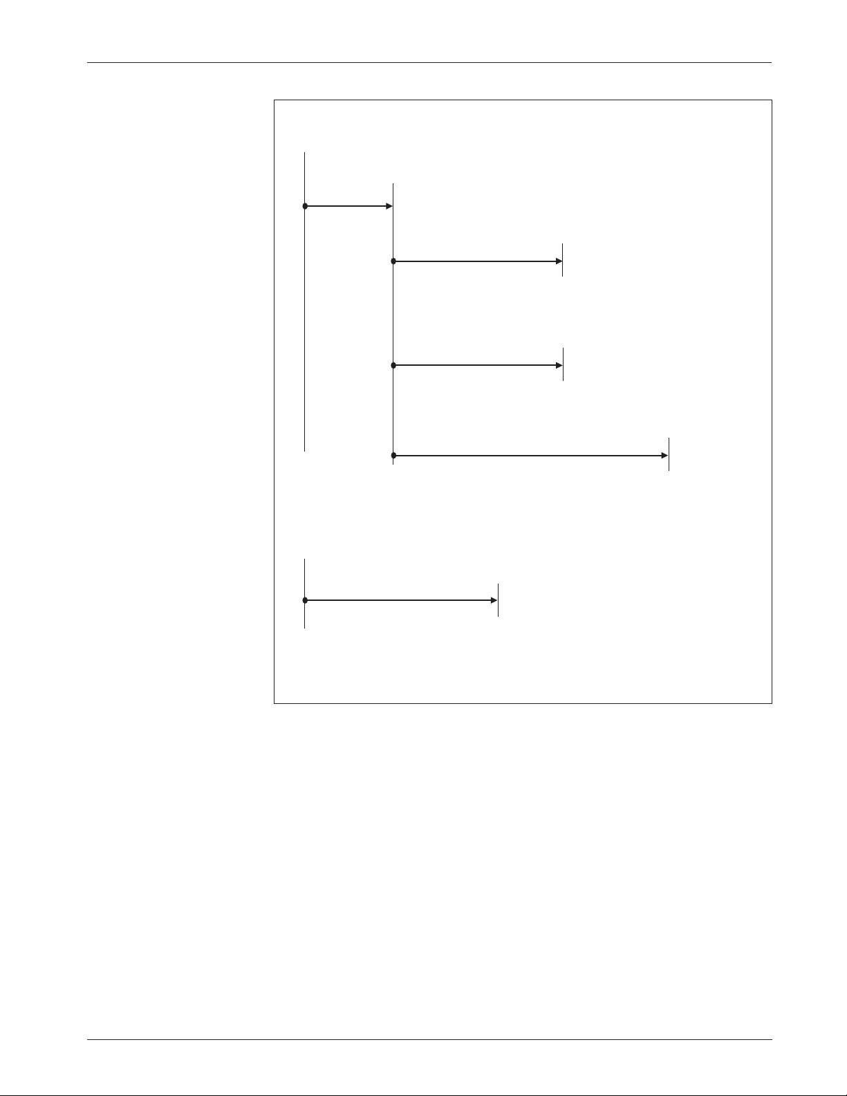
Curtis 1243GEN2 Manual
29
Fig. 14 The electromagnetic
brake parameters, in the
context of the 1243
GEN2
controller’s four delay
parameters (sequencing,
interlock brake, main
contactor open, and aux
delays). This figure assumes
the standard wiring
configuration, which
includes an EM brake.
For descriptions of the
sequencing delay and main
contactor open delay, see
pages 42 and 40.
Interlock Brake Delay
(0.0 – 8.0 s)
The EM brake engages unless it already engaged
at the completion of interlock braking.
Interlock braking from motor
(applied until motor speed approx. zero)
The EM brake engages unless it already engaged
at the expiration of Intk Brake Delay.
*
The neutral state is reached when, during normal operation,
the throttle is in neutral, both direction switches are open,
and the motor speed is approximately zero.
Aux Delay
(0.0 – 30.0 s)
EM brake engages,
for Aux Types 2, 3, and 4.
INTERLOCK
SWITCH
OPENS
VEHICLE
REACHES
NEUTRAL
STATE
*
Sequencing Delay
(0.0 – 3.0 s)
HPD fault (HPD Type 1)
SRO fault
Main Open Delay
(0.0 – 40.0 s)
Main
contactor
opens
3 — PROGRAMMABLE PARAMETERS:
Electromagnetic Brake Parameters
expired or when the motor speed approaches zero, whichever occurs first. The
Interlock Brake Delay is adjustable from 0.0 to 8.0 seconds. When set to zero,
there is no delay and the brake is engaged as soon as the interlock switch opens.
Interlock braking will still occur until the motor speed hits zero.
For Aux Type 5, the interlock braking delay does not apply.
Page 37

Curtis 1243GEN2 Manual
30
3 — PROGRAMMABLE PARAMETERS:
Electromagnetic Brake Parameters
Table 3 CONFIGURATION OPTIONS:
AUXILIARY DRIVER (Pin 8)
TYPE DESCRIPTION OF OPERATION
0 Aux driver disabled.
1 Electromagnetic brake used like a parking brake.
• The brake is released when the interlock switch closes.
• The brake is engaged as follows:
Interlock
The aux driver engages the brake when the interlock switch opens
and (a) the programmed Sequencing Delay and Interlock Brake Delay expire
or (b) the motor speed nears zero, whichever happens first.
Neutral State
* The aux driver does not respond to neutral state; there is no
therefore no Aux Delay.
Emerg. Rev.
The aux driver does not respond to emergency reverse.
2 Electromagnetic brake used to prevent rolling when stopping on a hill.
• The brake is released when the interlock switch closes
and either a direction switch or the emergency reverse switch closes.
• The brake is engaged as follows:
Interlock
Same as Type 1.
Neutral State
* When the vehicle reaches the neutral state, the aux driver
engages the brake as soon as the programmed Aux Delay expires.
Emerg. Rev.
After the emergency reverse switch has been applied and
released, the aux driver engages the brake as soon as the programmed Aux
Delay has expired. The Aux Delay timer starts when motor speed nears zero.
3 Electromagnetic brake functions as in
Type 2 except during Emerg. Rev.
Emerg. Rev. (a)
If both direction switches are open when the emergency
reverse switch is released, same as Type 2.
(b)
If a direction switch is closed
when the emergency reverse switch is released, the Aux Delay timer starts
when the emergency reverse switch is released.
4 Electromagnetic brake functions as in Type 1 except during Emerg. Rev.
Emerg. Rev.
Same as Type 3, except in situation
(a)
, where the aux driver
does not respond, and the brake therefore remains released.
5 Auxiliary device other than an electromagnetic brake.
This option is appropriate if the aux driver will be used for a brush or pump
motor contactor, for example, or for hydraulic steering assist. The aux driver
will be energized when the interlock switch and either a direction switch or
the emergency reverse switch are closed. The aux driver will turn off when
the programmed Aux Delay has expired after the interlock switch opens, or
both direction switches are opened while the vehicle is driving, or the
emergency reverse switch is released. The Aux Delay timer starts when
motor speed nears zero.
*
The neutral state is reached when, during normal operation, the throttle is in neutral, no
direction is selected (both direction switches open), and motor speed is approximately zero.
Page 38

Curtis 1243GEN2 Manual
31
M1–M4, MAX FWD SPD
The maximum forward speed parameter defines the maximum controller
voltage output at full throttle, in the forward direction. The maximum forward
speed parameter is adjustable from the programmed creep speed up to 100%.
It is tuned as part of the vehicle performance adjustment process (Section 5).
M1–M4, MAX REV SPD
The maximum reverse speed parameter defines the maximum controller
voltage output at full throttle, in the reverse direction. The maximum reverse
speed parameter is adjustable from 0% to 100%. It is tuned as part of the vehicle
performance adjustment process (Section 5).
CREEP SPEED
The creep speed parameter defines the initial controller output generated when
a direction is first selected. No applied throttle is necessary for the vehicle to
enter the creep mode, only a direction signal. The controller maintains creep
speed until the throttle is rotated out of the throttle deadband (typically 10%
of throttle).
Creep speed is adjustable from 0% to 25% of the controller output; it
cannot be set higher than the lowest programmed M1–M4 maximum forward
speed. The specified creep speed is not displayed as the throttle percent in the
programmer’s Test Menu when a direction is selected and zero throttle is
applied; only the 0% throttle command is displayed.
LOAD COMP
The load compensation parameter actively adjusts the applied motor voltage
as a function of motor load current. This results in more constant vehicle speeds
over variations in driving surface (ramps, rough terrain, etc.) without the vehicle
operator constantly adjusting the throttle position; it also helps equalize loaded
and unloaded vehicle speeds. The load compensation parameter is adjustable
from 0% to 25% of the controller’s PWM output. High values will cause the
controller to be more aggressive in attempting to maintain vehicle speed.
However, too much load compensation can result in jerky vehicle starts and
speed oscillation (“hunting”) when the vehicle is unloaded.
The load compensation parameter is tuned as part of the vehicle performance adjustment process (Section 5).
Speed Parameters
3 — PROGRAMMABLE PARAMETERS:
Speed Parameters
Page 39

Curtis 1243GEN2 Manual
32
3 — PROGRAMMABLE PARAMETERS:
Throttle Parameters
Throttle Parameters
THROTTLE TYPE
The 1243GEN2 controller accepts a variety of throttle inputs. Instructions are
provided in Section 2 for wiring the most commonly used throttles: 5kΩ–0 and
0–5kΩ 2-wire potentiometers, 3-wire potentiometers, 0–5V throttles, current
sources, and the Curtis ET-XXX electronic throttle.
The throttle type parameter can be programmed to 1, 2, 3, or 4. The
standard throttle input signal type options are listed in Table 4.
Table 4 PROGRAMMABLE THROTTLE TYPES
THROTTLE
TYPE DESCRIPTION
1 2-wire 5kΩ–0 potentiometer
2
single-ended
3-wire potentiometer with 1kΩ to 10kΩ range;
0–5V voltage source;
current source driving external resistor;
or Curtis ET-XXX electronic throttle
3 2-wire 0–5kΩ potentiometer
4
wigwag
3-wire potentiometer with 1kΩ to 10kΩ range;
0–5V voltage source;
or current source driving external resistor
THROTTLE DB
The throttle deadband parameter defines the throttle pot wiper voltage range
that the controller interprets as neutral. Increasing the throttle deadband setting
increases the neutral range. This parameter is especially useful with throttle
assemblies that do not reliably return to a well-defined neutral point, because it
allows the deadband to be defined wide enough to ensure that the controller goes
into neutral when the throttle mechanism is released.
Examples of deadband settings (0%, 10%, 40%) are shown in Figure 15
for the four throttle types (see Table 4). In all the examples in Figure 15, the
throttle max parameter is set at 100%.
The throttle deadband parameter is adjustable from 0% to 40% of the
nominal throttle wiper range; the default setting is 10%. The nominal throttle
wiper voltage range depends on the throttle type selected. See Table 1 (page 9)
for the characteristics of your selected throttle type.
The throttle deadband is tuned as part of the vehicle performance adjustment process (Section 5).
Page 40
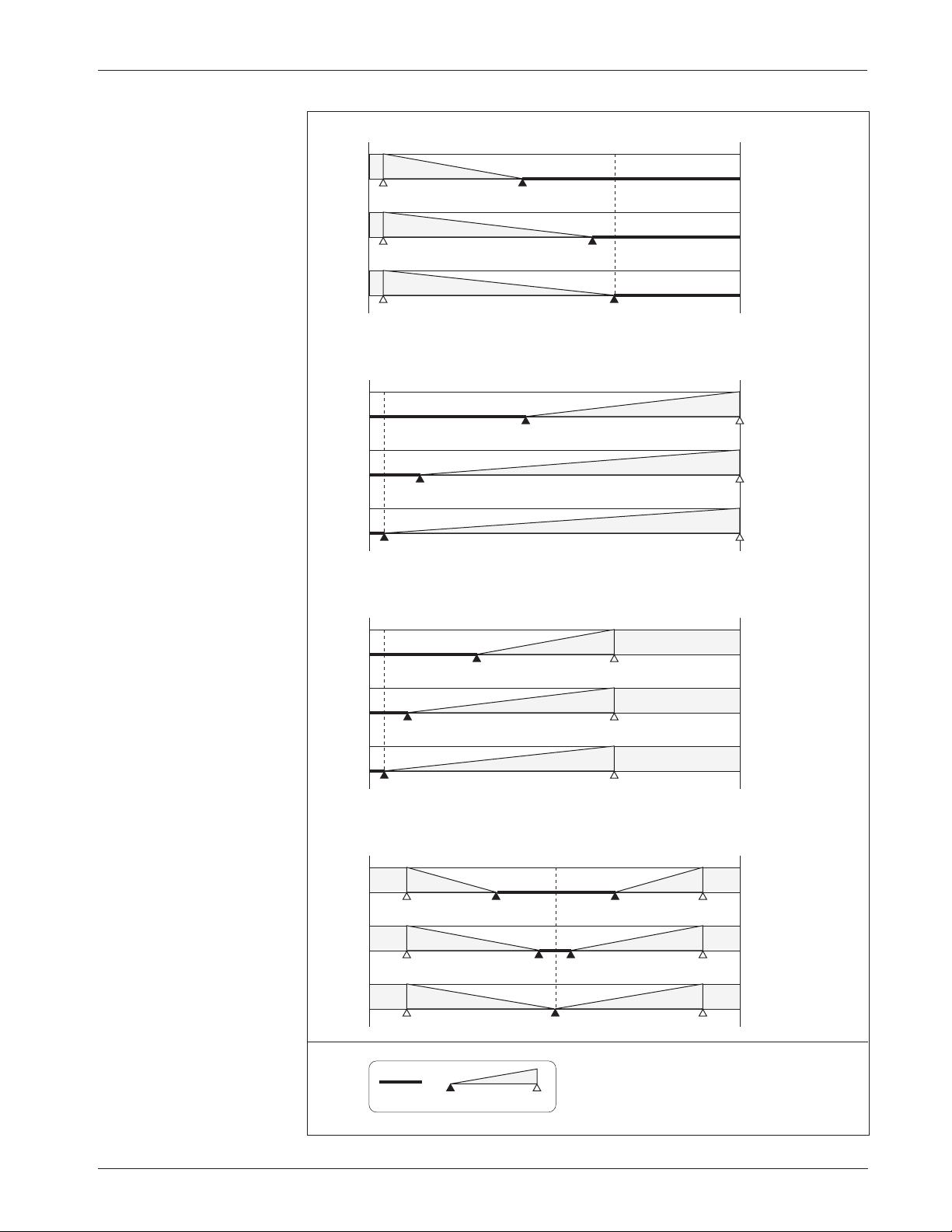
Curtis 1243GEN2 Manual
33
3 — PROGRAMMABLE PARAMETERS:
Throttle Parameters
Fig. 15 Effect of adjusting
the Throttle Deadband
parameter.
Throttle Type 3 (0–5kΩ)
Throttle Type 2 (0–5V, single-ended)
Throttle Type 1 (5kΩ–0)
Throttle Type 4 (0–5V, wigwag)
5V
0
0.2V
(0
Ω)
40% Deadband
10% Deadband
0% Deadband
0.5V
(450
Ω)
1.4V
(2.0k
Ω)
Notes: Voltages shown are at the pot wiper relative to B-.
For throttle types 1 and 3, the deadband points are
defined in terms of the nominal 5k
Ω pot resistance.
Using a pot of greater or lesser resistance will give
different values for the deadband points.
Throttle Max parameter set at 100%.
3.3V
(5.0k
Ω)
5V
0
0.2V
40% Deadband
10% Deadband
0% Deadband
0.7V
2.1V
5V
0
3.3V
(5.0k
Ω)
40% Deadband
10% Deadband
0% Deadband
3.0V
(4.5k
Ω)
2.1V
(3.0k
Ω)
0.2V
(0
Ω)
3.3V
(5.0kΩ)
3.3V
(5.0k
Ω)
0.2V
(0Ω)
0.2V
(0
Ω)
KEY
100%
Neutral
Deadband
Controller
Output
0%
5V
0
0.5V
40% Deadband
10% Deadband
0% Deadband
2.7V
3.3V
4.5V
4.5V
4.5V
2.5V
0.5V
0.5V
2.3V
1.7V
Page 41
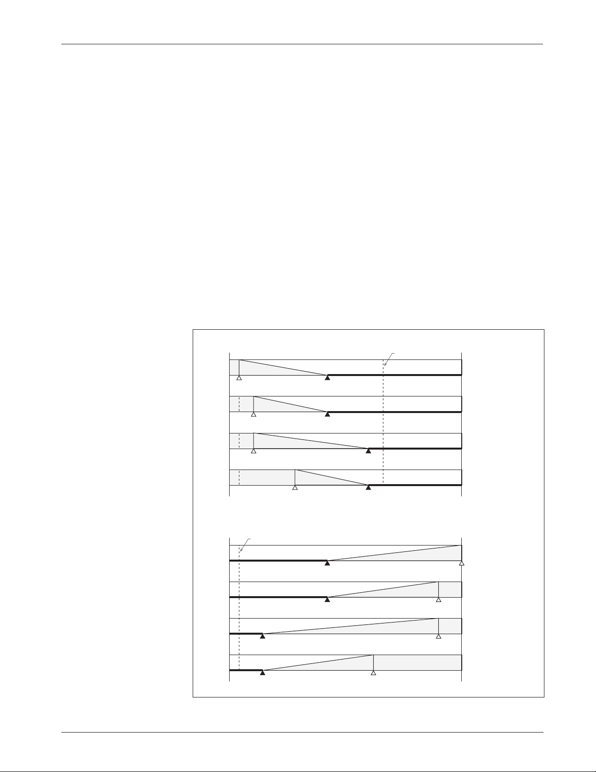
Curtis 1243GEN2 Manual
34
3 — PROGRAMMABLE PARAMETERS:
Throttle Parameters
THROTTLE MAX
The throttle max parameter sets the wiper voltage or resistance required to
produce 100% controller output. Decreasing the throttle max setting reduces
the wiper voltage or resistance and therefore the full stroke necessary to produce
full controller output. This feature allows reduced-range throttle assemblies to
be accommodated.
The examples in Figure 16 illustrate the effect of three different throttle
max settings (100%, 90%, 60%) on the full-stroke wiper voltage or resistance
required to attain 100% controller output for the four throttle types.
The programmer displays the throttle max parameter as a percentage of
the active throttle range. The active throttle range is not affected by the throttle
deadband setting. The throttle max parameter can be adjusted from 100% to
60%; the default setting is 90%. The nominal throttle wiper range depends of
the throttle type selected. See Table 1 (page 9) for the characteristics of your
selected throttle type.
The throttle max parameter is tuned as part of the vehicle performance
adjustment process (Section 5).
Fig. 16 Effect of adjusting
the Throttle Max parameter
(throttle types 1 and 2).
Throttle Type 2 (0–5V, single-ended)
Throttle Type 1 (5kΩ–0)
0
5V
2.1V
100% Throttle Max
40% Deadband
0.7V
4.5V
0.7V
3.1V
2.1V
4.5V
90% Throttle Max
40% Deadband
90% Throttle Max
10% Deadband
60% Throttle Max
10% Deadband
0
5V
2.1V
(3.0kΩ)
0.2V
(0Ω)
100% Throttle Max
40% Deadband
3.0V
(4.5kΩ)
1.4V
(2.0kΩ)
0.5V
(450Ω)
90% Throttle Max
40% Deadband
90% Throttle Max
10% Deadband
60% Throttle Max
10% Deadband
0.5V
(450Ω)
2.1V
(3.0kΩ)
3.0V
(4.5kΩ)
3.3V (5kΩ)
0.2V
Page 42
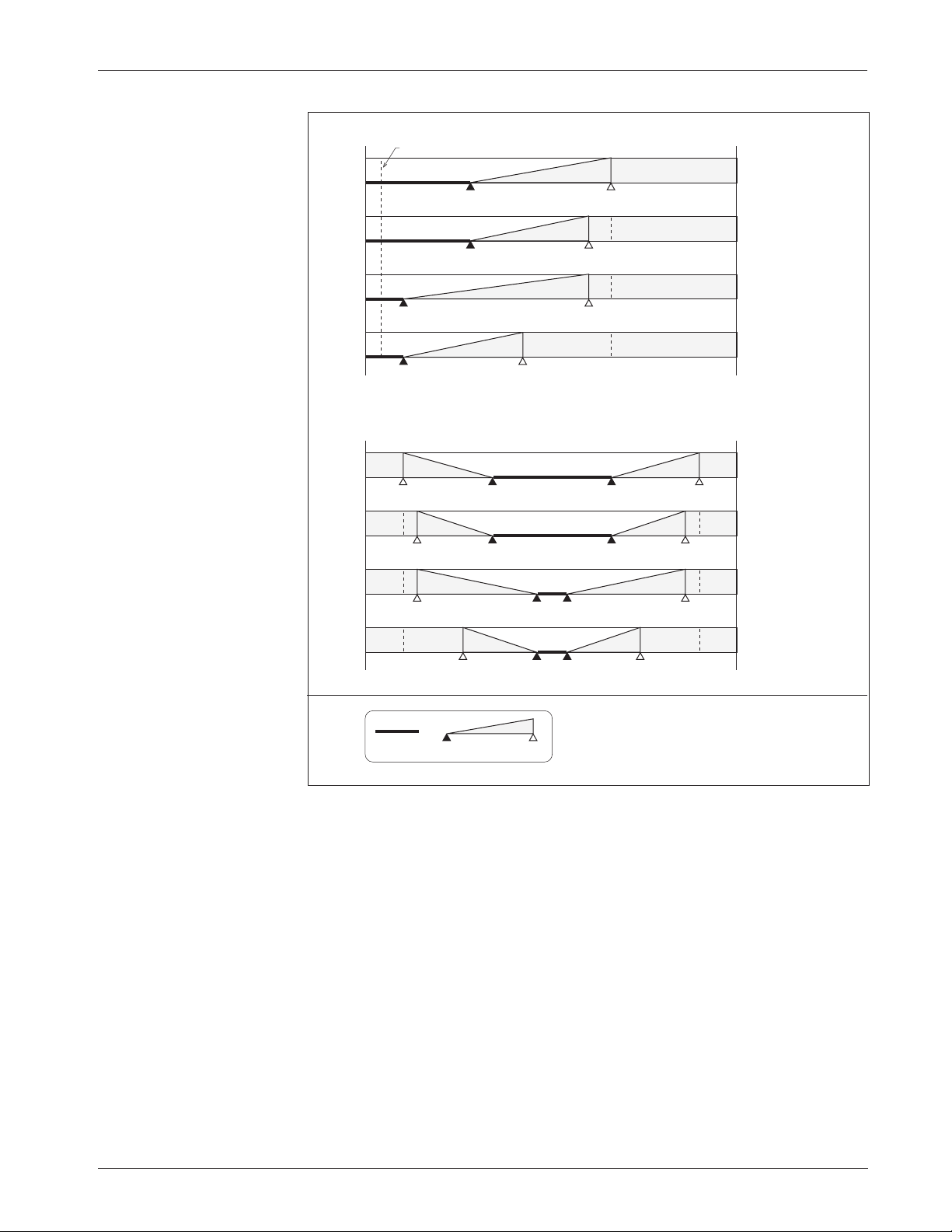
Curtis 1243GEN2 Manual
35
3 — PROGRAMMABLE PARAMETERS:
Throttle Parameters
Fig. 16, cont.
Effect of adjusting the
Throttle Max parameter
(throttle types 3 and 4).
Throttle Type 3 (0–5kΩ)
Throttle Type 4 (0–5V, wigwag)
0
5V
1.4V
(2.0k
Ω)
3.3V
(5.0kΩ)
100% Throttle Max
40% Deadband
0.5V
(400
Ω)
2.1V
(3.0 k
Ω)
3.0V
(4.5k
Ω)
90% Throttle Max
40% Deadband
90% Throttle Max
10% Deadband
60% Throttle Max
10% Deadband
Notes: Voltages shown are at the pot wiper relative to B-.
For throttle types 1 and 3, the deadband points are
defined in terms of the nominal 5k
Ω pot resistance.
Using a pot of greater or lesser resistance will give
different values for the deadband points.
KEY
100%
Neutral
Deadband
Controller
Output
0%
1.4V
(2.0k
Ω)
0.5V
(400
Ω)
3.0V
(4.5k
Ω)
0
5V
100% Throttle Max
40% Deadband
90% Throttle Max
40% Deadband
90% Throttle Max
10% Deadband
60% Throttle Max
10% Deadband
3.3V
4.5V
0.5V
1.7V
3.3V
4.3V
0.7V
1.7V
2.7V
4.3V
0.7V
2.3V
2.7V
3.7V
1.3V
2.3V
0.2V (0
Ω)
Page 43
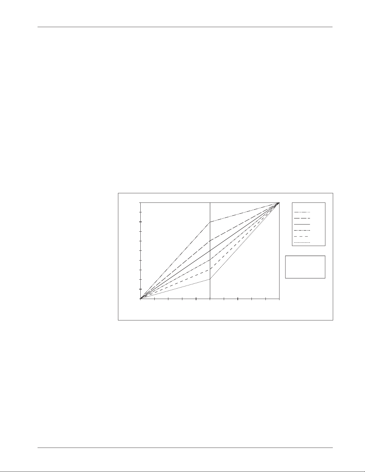
Curtis 1243GEN2 Manual
36
Fig. 17 Throttle maps for
controller with maximum
speed set at 100% and
creep speed set at 0.
THROTTLE INPUT (percent of active range)
CONTROLLER OUTPUT (percent PWM)
80%
60%
50%
40%
30%
20%
THROTTLE MAP
100
90
80
70
60
50
40
30
20
10
0
100908070605040302010 0
SPEED PARAMETERS
0% Creep Speed
100% Max Speed
3 — PROGRAMMABLE PARAMETERS:
Throttle Parameters
THROTTLE MAP
The throttle map parameter modifies the vehicle’s response to the throttle
input. The throttle map parameter’s default setting of 50% provides a linear
output response to throttle position. Values below 50% reduce the controller
output at low throttle, providing enhanced slow speed maneuverability. Values
above 50% give the vehicle a faster, more responsive feel at low throttle.
The throttle map setting can be programmed between 20% and 80%.
The setting refers to the PWM output at half throttle, as a percentage of the
throttle’s full active range. The throttle’s active range is the voltage or resistance
between the 0% modulation point (the throttle deadband threshold) and the
100% modulation point (the throttle max threshold).
With creep speed set at 0 and maximum speed set 100%, a 50% throttle
map setting will give 50% output at half throttle. A throttle map setting of 80%
will give 80% output at half throttle. Six throttle map profiles (20, 30, 40, 50,
60, and 80%) are shown in Figure 17; in all these examples the creep speed is
set at 0 and the maximum speed at 100%.
Changing either of the speed parameters changes the characteristics of the
controller output relative to the throttle input and hence the throttle response.
Controller output is always a percentage of the range defined by the speed
parameters (the range between the creep speed and maximum speed settings).
This means that controller output will begin to increase above the set creep
speed as soon as the throttle exceeds the neutral deadband threshold. Controller
output will continue to increase as the throttle input increases and will reach
maximum output when the throttle input reaches the throttle max threshold.
The maximum controller output at this point is defined by the value of the
maximum speed parameter.
Page 44
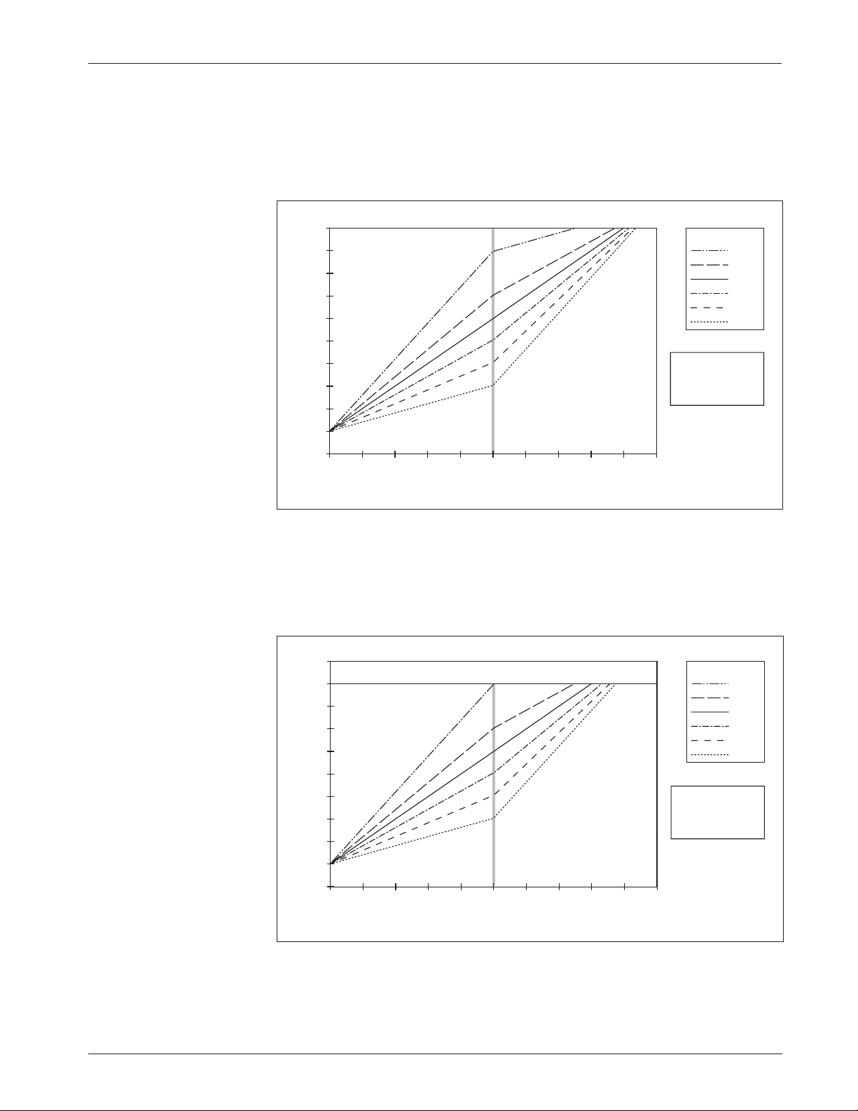
Curtis 1243GEN2 Manual
37
THROTTLE INPUT (percent of active range)
CONTROLLER OUTPUT (percent PWM)
80%
60%
50%
40%
30%
20%
THROTTLE MAP
100
90
80
70
60
50
40
30
20
10
0
100908070605040302010 0
SPEED PARAMETERS
10% Creep Speed
90% Max Speed
Fig. 19 Throttle maps for
controller with maximum
speed set at 90% and
creep speed set at 10%.
THROTTLE INPUT (percent of active range)
CONTROLLER OUTPUT (percent PWM)
80%
60%
50%
40%
30%
20%
THROTTLE MAP
100
90
80
70
60
50
40
30
20
10
0
100908070605040302010 0
SPEED PARAMETERS
10% Creep Speed
100% Max Speed
3 — PROGRAMMABLE PARAMETERS:
Throttle Parameters
Fig. 18 Throttle maps for
controller with maximum
speed set at 100% and
creep speed set at 10%.
Reducing the max speed setting clips off the top of the throttle map.
Figure 19 shows throttle map curves with the same 10% creep speed setting and
the maximum speed setting dropped to 90%. The curves in this example are
exactly as in Figure 18, except the PWM output hits a ceiling at 90%.
The throttle map is tuned as part of the vehicle performance adjustment
process (Section 5).
Increasing the creep speed value adds to the applied throttle and simply
shifts the curves up. As shown in Figure 18, a creep speed setting of 10% with
the Throttle Map set at 50% gives 60% PWM output (50% + 10%) at half
throttle.
Page 45

Curtis 1243GEN2 Manual
38
3 — PROGRAMMABLE PARAMETERS:
Field Parameters
POT LOW FAULT
The pot low fault parameter allows the controller’s pot low fault detection to
be disabled. This is useful when single-wire, ground (B-) referenced voltage
throttle inputs are used. Setting the pot low fault parameter to Off disables the
fault detection at the pot low input (Pin 7). It is recommended that the pot low
fault parameter be set to On in any application where a resistive throttle is used.
This will provide the most comprehensive throttle fault detection and provide
the safest possible vehicle operation.
Note: The programmer’s display name for the pot low fault is “Throttle
Wiper Lo.”
FIELD MIN
The minimum field current limit parameter defines the minimum allowed
field current, thus determining the vehicle’s maximum speed. Field Min can be
adjusted from 1.6 amps up to the lowest programmed M1–M4 Restraint value.
The Field Min parameter is tuned as part of the vehicle performance
adjustment process (Section 5).
FIELD MAX
The maximum field current limit parameter defines the maximum allowed
field current. The maximum field current limit setting determines the vehicle’s
maximum torque and the maximum power that the field winding will have to
dissipate. Field Max can be adjusted from the programmed Field Min value up
to the controller’s full rated field current. (The full rated field current depends
on the controller model; see specifications in Table D-1).
The Field Max parameter is tuned as part of the vehicle performance
adjustment process (Section 5).
FLD MAP START
The field map start parameter defines the armature current at which the field
map starts to increase from the programmed Field Min value. This parameter
is adjustable from 25 amps up to the full rated armature current value. (The full
rated armature current depends on the controller model; see specifications in
Table D-1).
The field map start parameter is used to equalize the vehicle’s maximum
speed when loaded and unloaded. Increasing the field map start parameter
value will increase the maximum load weight that the vehicle can carry while
maintaining maximum speed on a level surface.
The field map start parameter is tuned as part of the vehicle performance
adjustment process (Section 5).
Field Parameters
Page 46
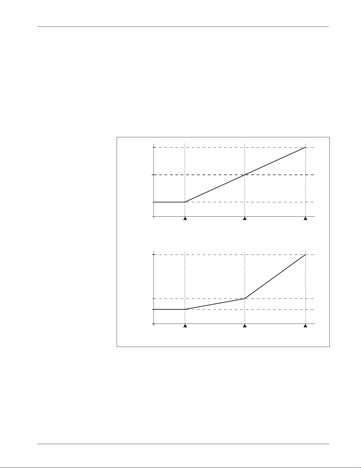
Curtis 1243GEN2 Manual
39
3 — PROGRAMMABLE PARAMETERS:
Field Parameters
FIELD MAP
The field map defines the relationship between armature current and field
current under steady-state drive conditions. The shape of the field map is
determined by the programmed Field Min, Field Max, Field Map, Field Map
Start, and M1-M4 Drive C/L settings.
As shown in Figure 20, the field map parameter adjusts the field current
at the Field Map Midpoint, which is located halfway between the programmed
Field Map Start and the programmed M1-M4 Drive C/L. With the field map
parameter set at 50%, the motor’s field current increases linearly with increasing
armature current—thus emulating a series wound motor.
Fig. 20 Field current
relative to armature
current, with field map
parameter set at 50%
and 20%.
ARMATURE CURRENT
FIELD CURRENT
Field Map Start Field Map Midpoint 100%
Drive C/L
0
0
Field Min
Field Max
Field Map
(50%)
ARMATURE CURRENT
FIELD CURRENT
Field Map Start Field Map Midpoint 100%
Drive C/L
0
0
Field Min
Field Max
Field Map
(20%)
Decreasing the field map parameter reduces the field current at a given
armature current. As the field current is reduced, the motor will be able to
maintain speeds closer to the maximum speed value as its load increases;
however, the motor’s capability to produce torque at these higher speeds will
decrease. With the Field Map reduced to 20%, the field current at the Field
Map Midpoint will exceed Field Min by 20% of the range between Field Min
and Field Max.
The field map parameter is tuned as part of the vehicle performance
adjustment process (Section 5).
Page 47

Curtis 1243GEN2 Manual
40
FIELD CHECK
The field check parameter determines whether the field diagnostics will be active.
When programmed On, the controller checks for field open and field shorted faults.
This parameter is typically programmed On except in series motor applications,
or where the motor resistance is too high to provide valid fault data.
MAIN CONT INTR
The main contactor interlock parameter allows the OEM to define a dual
switch requirement to operate the vehicle. When this parameter is programmed
On, the controller requires that both KSI (Pin 16) and the interlock input
(Pin 15) be pulled high (to B+) before the controller will engage the main
contactor. The main contactor will open after the interlock switch is opened and
the sequencing delay expires. If this parameter is programmed Off, only the KSI
input is required for the main contactor to be engaged.
After changing the main contactor interlock setting, KSI must be cycled
for the new setting to take effect.
MAIN OPEN DLY
The main contactor open delay parameter is applicable only if the main
contactor driver interlock has been programmed On. The delay can then be set
to allow the contactor to remain engaged for a period of time after the interlock
switch is opened. The delay is useful for preventing unnecessary cycling of the
contactor and for maintaining power to auxiliary functions, such as a steering
pump motor, that may be used for a short time after the interlock switch has
opened. The main contactor open delay is programmable from 0 to 40 seconds.
After the interlock switch is opened, the programmed sequencing delay
must expire before the main contactor open delay timer starts counting.
Therefore, the time between the interlock switch opening and the main
contactor disengaging is the sum of the sequencing delay and the main contactor
open delay (see Figure 14, page 29.)
CONT DIAG
The main contactor diagnostics parameter, when programmed On, enables
two checks to verify that the main contactor is present and that it has not welded
closed. Each time the main contactor is commanded to engage, the controller
first performs a main contactor welded test to verify that it is not already closed.
The controller then engages the contactor and performs a missing contactor test
to confirm that the contactor successfully engaged.
These checks are not performed if the main contactor diagnostics parameter is programmed Off. The main contactor
driver, however, is always pro-
tected from overcurrents, short circuits, and overheating.
3 — PROGRAMMABLE PARAMETERS:
Main Contactor Parameters
Main Contactor Parameters
Page 48

Curtis 1243GEN2 Manual
41
3 — PROGRAMMABLE PARAMETERS:
Sequencing Fault Parameters
ANTI-TIEDOWN
The anti-tiedown feature prevents operators from taping or “tying down” the
mode select switches in order to operate permanently in Mode 2 or Mode 4
(which are typically the higher speed modes). Each time the interlock switch
closes, the anti-tiedown feature checks which mode is selected. If the mode select
switches are requesting Mode 2 or Mode 4 (Mode Select 1 switch closed), the
controller will default to Mode 1 or Mode 3, depending on the position of the
Mode Select 2 switch, and an anti-tiedown fault will be declared. The controller
will then remain in Mode 1 or Mode 3 until the Mode Select 1 switch is released
and reactivated. The anti-tiedown feature can be programmed On or Off.
HPD
The high pedal disable (HPD) feature prevents the vehicle from driving if
greater than 25% throttle is already applied upon startup. In addition to
providing routine smooth starts, HPD also prevents accidental sudden starts if
problems in the throttle linkage (e.g., bent parts, broken return spring) give a
throttle input signal to the controller even with the throttle released.
HPD requires the controller to receive a KSI input and an interlock input
(HPD Type 1)—or simply a KSI input (HPD Type 2)—before receiving a
throttle input greater than 25%; if the inputs are not received in the proper
sequence, the controller will inhibit output to the motor. An HPD fault can be
cleared by reducing the throttle demand to less than 25%.
HPD fault detection can be turned off by setting the HPD Type to 0. To
meet EEC requirements, HPD must be programmed to Type 1 or Type 2.
Note: The conditions for HPD faults are not affected by whether the
main contactor interlock parameter is On or Off.
HPD Type 0
:
No HPD fault detection
HPD Type 1
:
KSI+interlock
To drive the vehicle, the controller must receive both a KSI input and an interlock
input before receiving a >25% throttle input. Any other sequence will result in
an HPD fault that will prevent the vehicle from being driven.
With HPD Type 1, the sequencing delay parameter can be used to prevent
HPD faults that would otherwise occur from momentary opening of the
interlock switch while driving (see Figure 14, page 29). If the interlock switch
is opened and then quickly closed before the programmed sequencing delay
elapses, no HPD fault will be declared and operation will not be interrupted.
HPD Type 2
:
KSI only
To drive the vehicle, the controller must receive a KSI input before receiving a
throttle input greater than 25%. Violation of this sequence will result in an HPD
fault that will prevent the vehicle from being driven. With HPD Type 2, if
Sequencing Fault Parameters
Page 49

Curtis 1243GEN2 Manual
42
throttle is applied after the KSI input has been received but before the interlock
switch is closed, the vehicle will accelerate to the requested speed as soon as the
interlock switch is closed.
SRO
The static return to off (SRO) feature prevents the vehicle from being started
when “in gear,” i.e., with a direction already selected. SRO checks the sequencing of the KSI and interlock inputs relative to a direction input. SRO faults can
result from using an incorrect sequence, or from using a correct sequence with
less than 50 msec between steps. If an SRO fault is declared, the controller will
inhibit output to the motor until the fault is cleared by using an acceptable
sequence.
The sequencing delay can be used to prevent SRO faults that would
otherwise occur from momentary opening of the interlock switch while driving
(see Figure 14, page 29). If the interlock switch is opened and then quickly
closed before the programmed delay time elapses, no SRO fault will be declared
and operation will not be interrupted.
Note: The conditions for SRO faults are not affected by whether the main
contactor interlock parameter is On or Off.
Three types of SRO are available, along with a “no SRO” option.
SRO Type 0
:
No SRO fault detection
SRO Type 1
:
KSI and Interlock before direction input
To drive the vehicle, the controller must receive both a KSI input and an
interlock input before receiving an input from either direction switch. The order
in which the KSI and interlock inputs are received does not matter, only that
they are both received before a direction input.
SRO Type 2
:
KSI before Interlock before direction input
To drive the vehicle, the controller must receive a KSI input and then an
interlock input before receiving an input from either direction switch.
SRO Type 3
:
KSI before Interlock before forward input
Type 3 SRO is useful for walkie vehicles that frequently operate on ramps. To drive
the vehicle in the forward direction, the controller must receive the KSI, interlock,
and forward inputs in that order, as in SRO Type 2. However, this sequence is
not required for operation in reverse. With SRO Type 3, a reverse input is
allowed at any place in the sequence: i.e., before interlock, or even before KSI.
SEQUENCING DLY
The sequencing delay feature allows the interlock switch to be cycled within a
set time—the sequencing delay—without activating HPD or SRO. This
feature is useful in applications where the interlock switch may bounce or be
3 — PROGRAMMABLE PARAMETERS:
Sequencing Fault Parameters
Page 50

Curtis 1243GEN2 Manual
43
momentarily cycled during operation. However, it is important to bear in mind
that the same sequencing delay also delays the initiation of interlock braking (see
Figure 14, page 29).
The sequencing delay can be programmed from 0.0 to 3.0 seconds, with
0.0 corresponding to no delay.
The polarity of the
S1
and S2 connections will affect the operation of the emergency
reverse feature. The forward and reverse switches and the S1 and S2 connections must
be configured so that the vehicle drives away from the operator when the emergency
reverse button is pressed.
EMR REV C/L
When emergency reverse is activated, the emergency reverse current limit
parameter defines the maximum braking current during deceleration and the
maximum drive current after the vehicle switches direction. The emergency
reverse current limit is adjustable from 50 amps up to the controller’s full rated
braking current. (The full rated braking current depends on the controller
model; see specifications in Table D-1).
EMR REV CHECK
The emergency reverse check parameter is applicable only when the emergency
reverse feature is being used in the application. If emergency reverse is not being
used, this parameter should be set to Off.
When enabled (programmed On), the emergency reverse check tests for
continuity from the emergency reverse check output (Pin 10) to the emergency
reverse input (Pin 13). Therefore, the emergency reverse wiring should be
connected as closely as possible to the controller side of the emergency reverse
switch. The recommended wiring is shown in the standard wiring diagram,
Figure 3 (page 7).
EMR DIR INTR
In applications that use the emergency reverse feature, the emergency reverse
direction interlock parameter defines the requirements for resuming normal
operation after using emergency reverse. After emergency reverse has been used,
the controller sets the output drive to zero regardless of whether a direction or
throttle is being requested. With the emergency reverse direction interlock
parameter set to On, the operator can either open both direction switches or
cycle the interlock switch to enable normal operation. With the emergency
reverse direction interlock parameter set to Off, the only way for the operator
to resume normal operation is by cycling the interlock switch.
3 — PROGRAMMABLE PARAMETERS:
Emergency Reverse Parameters
Emergency Reverse Parameters
☞
C A U T I O N
Page 51

Curtis 1243GEN2 Manual
44
The 1243
GEN2 controller can protect the motor from damage due to overtemperature
by cutting back the motor speed. An estimate of the motor temperature is derived from
the resistance of the field winding. The controller measures field current, field PWM,
and battery voltage, and uses these measurements to calculate the instantaneous field
resistance. This value is filtered and compared to two setpoints: Motor Warm
Resistance and Motor Hot Resistance. If the field resistance reaches the Motor Warm
Resistance setpoint, the motor maximum speed will be limited to the programmed
Warm Speed. If the field resistance reaches the Motor Hot Resistance setpoint, the
controller will no longer drive but all braking functions will remain active. If this
motor protection feature is not desired, it can be disabled by programming the motor
resistance compensation parameter Off.
WARM SPEED
The warm speed parameter defines the maximum drive speed output when the
motor field resistance is at or above the Motor Warm Resistance setpoint. The
warm speed is adjustable from 0 to 100% of drive output.
MOT WRM x10 mΩ
The motor warm resistance parameter defines the field resistance setpoint at
which a motor warm fault will occur and the maximum speed will be controlled
by the Warm Speed setting.
Note: The parameter value is in ten-milliohm units. If you want to program
the Motor Warm Resistance setpoint to 900 mΩ (0.9 Ω), you would enter 90
for the MOT WRM x10 mΩ value. The Motor Warm Resistance setpoint is adjust-
able from 100 mΩ (MOT WRM x10 mΩ =10) up to the Motor Hot Resistance
setpoint.
MOT HOT x10 mΩ
The motor hot resistance parameter defines the field resistance setpoint at
which a motor hot fault will occur and no drive output will be allowed. It is
adjustable from the Motor Warm Resistance setpoint up to 2500 mΩ (2.5 Ω).
The value entered is in ten-milliohm units, which means the maximum Motor
Hot Resistance value is one-tenth of 2500 (i.e., MOT HOT x10 m
Ω =250).
MOT Ω COMP
The motor resistance compensation parameter is used (programmed On) to
enable the motor overtemperature protection feature.
Motor Protection Parameters
3 — PROGRAMMABLE PARAMETERS:
Motor Protection Parameters
Page 52

Curtis 1243GEN2 Manual
45
3 — PROGRAMMABLE PARAMETERS:
Hourmeters
Two individual hourmeters are built into the 1243GEN2 controller, each with nonvolatile memory:
• a total hourmeter, that measures the total operating time (KSI on-time), and
• a traction hourmeter, that measures the time that a direction is selected.
Each hourmeter has a corresponding service timer and disable timer. Hourmeter
information is viewable via the programmer or the Spyglass display.
For each hourmeter, the service timer is used to set the time before scheduled
maintenance is due. When the set service time expires, the service warning fault
occurs and the disable timer starts. If the programmed disable time expires before the
scheduled maintenance is performed, the controller defaults to the programmed
traction fault speed.
The 1243GEN2 controller is shipped from the factory with each of its two hourmeters
preset to 0. If the controller is being installed in a new vehicle, these presets do not
need to be adjusted. If the controller is being installed in a “used” vehicle, however,
it may be desirable to transfer the existing hourmeter values to the new controller. To
do this, the existing hourmeter values must be entered as follows.
Each meter records time to 999999.9 hours (114 years), and will roll over to
000000.0 if this is exceeded. The adjust high, adjust middle, and adjust low
parameters each set two of the digits on the meter: HHMMLL.
ADJ HOURS HIGH
The adjust hours high parameter is used to set the highest two digits, from 00
to 99.
ADJ HOURS MID
The adjust hours middle parameter is used to adjust the middle two digits,
from 00 to 99.
ADJ HOURS LOW
The adjust hours low parameter is used to adjust the lowest two digits, from
00 to 99. It is not possible to set tenths.
SET TOTL HRS
The set total hours parameter is used to apply the preset high, middle, and low
values to the total (i.e., KSI on-time) hourmeter. First, adjust the preset values
as desired for the total hourmeter. Then, program the Set Total Hours parameter
On, which automatically loads the preset values.
Hourmeter Parameters
Hourmeter “Preset” Settings
Page 53

Curtis 1243GEN2 Manual
46
3 — PROGRAMMABLE PARAMETERS:
Hourmeters
Once the preset values have been loaded, the Set Total Hours parameter
should be programmed Off.
SET TRAC HRS
The set traction hours parameter is used to apply preset high, middle, and low
values to the traction hourmeter. First, adjust the preset values as desired for the
traction hourmeter. Then, program the Set Traction Hours parameter On,
which automatically loads the preset values. Once they have been loaded, the Set
Traction Hours parameter should be programmed Off.
SRVC TOTL HRS
The total service hours parameter is used to set the timer for the next scheduled
overall maintenance. The service interval can be up to 5,000 hours. The total
service timer is adjustable between 0.0 and 50.0, in 0.5 increments, with 25.0
being equivalent to 2,500 hours (25.0 × 100).
Setting the parameter to 0 means that the timer will never expire—i.e.,
there will be no overall maintenance reminder.
SRVC TRAC HRS
The traction service hours parameter is used to set the timer for the next
scheduled traction motor maintenance. The service interval can be up to 5,000
hours. The traction service timer is adjustable between 0.0 and 50.0, in 0.5
increments, with 25.0 being equivalent to 2,500 hours (25.0 × 100).
Setting the parameter to 0 means that the timer will never expire—i.e.,
there will be no motor maintenance reminder.
DIS TOTL HRS
The total disable hours parameter is used to set the total disable timer; it can
be adjusted between 0 and 250 hours, in 1 hour increments. If the total disable
timer expires, the traction fault speed goes into effect.
Setting the parameter to 0 means that the total disable timer will never
expire and therefore never invoke the traction fault speed.
DIS TRAC HRS
The traction disable hours parameter is used to set the traction disable timer;
it can be adjusted between 0 and 250 hours, in 1 hour increments. If the traction
disable timer expires, the traction fault speed goes into effect.
Hourmeter Service Timer Setting
Hourmeter Disable Timer Setting
Page 54

Curtis 1243GEN2 Manual
47
3 — PROGRAMMABLE PARAMETERS:
Hourmeters
Setting the parameter to 0 means that the traction disable timer will never
expire and therefore never invoke the traction fault speed.
TRAC FAULT SPD
The traction fault speed parameter sets the maximum drive speed in the event
the traction disable timer expires or the total disable timer expires; it can be
adjusted between 0–100% of drive output, and applies to all modes.
The hourmeter service timers must be reset (programmed Off ) after service is
performed, using the Service Total and Service Traction parameters.
Occasionally, the vehicle may be brought in for servicing before its scheduled
maintenance is due—for example, because of some specific problem. You might want
to check the service timers at this time to see how many hours they have accumulated.
If routine maintenances is due shortly, you could perform it now instead, and reset
the appropriate service timer—thus avoiding an extra trip to the shop.
SERVICE TOTL
When the total service timer expires, the controller automatically sets the
service total parameter On. The Service Total parameter must then be programmed Off to indicate the appropriate service has been performed.
If a vehicle is brought in for service before a service warning is issued, you
can check the accumulated total service hours. Plug in the 1311 programmer
and go to the Monitor menu. Multiply the “Tot Srvc X25” value by 25 and add
the “+Tot Srvc” value; this is how many total hours have elapsed since the total
service timer was last reset.
When service is performed before the total service timer expires, the
Service Total parameter must be programmed On and then Off to reset it.
SERVICE TRAC
When the traction service timer expires, the controller automatically sets the
service traction parameter On. The Service Traction parameter must then be
programmed Off to indicate the appropriate service has been performed.
If a vehicle is brought in for service before a service warning is issued, you
can check the accumulated traction service hours. Plug in the 1311 programmer and go to the Monitor menu. Multiply the “Trac Srvc X25” value by 25
and add the “+Trac Srvc” value; this is how many traction hours have elapsed
since the traction service timer was last reset.
When service is performed before the traction service timer expires, the
Service Traction parameter must be programmed On and then Off to reset it.
Hourmeter Service Timer Resetting
Page 55

Curtis 1243GEN2 Manual
48
3 — PROGRAMMABLE PARAMETERS:
Hourmeters
HOURMETER TYPE
The Spyglass gauge displays hourmeter data for 5 seconds each time the
keyswitch is turned on. The hourmeter type parameter defines whether the
total hourmeter or traction hourmeter data will be displayed. When this
parameter is programmed On, the total hourmeter is displayed; when programmed Off, the traction hourmeter is displayed.
PUMP METER
The pump meter parameter, when programmed On, configures the Fault
Output 1 line (at Pin 2) to function as an input to measure the hours a pump
is running. The pump is considered to be running when Pin 2 is at the battery
voltage. When the pump meter parameter is programmed On, the traction
hourmeter serves as a combination traction/pump hourmeter, and all the above
“TRAC” hourmeter parameters apply to both traction hours and pump hours.
The traction/pump hourmeter counts the hours when a direction is selected and
the hours when the pump is running.
Other Hourmeter Parameters
Page 56

Curtis 1243GEN2 Manual
49
3 — PROGRAMMABLE PARAMETERS:
BDI
The battery discharge indicator constantly calculates the battery state-of-charge
whenever KSI is on. When KSI is turned off, the present battery state-of-charge is
stored in non-volatile memory. BDI information is viewable via the Spyglass display
and via the 1311 programmer’s Monitor Menu as BDI%. Three parameters are used
to adjust the display.
The standard values for flooded lead acid and sealed maintenance-free batteries
are listed below.
BATTERY TYPE
FLOODED SEALED
Full volts (VPC) 2.04 2.04
Empty volts (VPC) 1.74 1.91
Reset volts (VPC) 2.10 2.10
Custom values can be entered based on specific batteries in consultation with a Curtis
applications engineer.
Note: BDI values are set without the decimal point; 2.04 volts per cell, for
example, will appear as 204 (i.e., VPC × 100) on the programmer. The Full,
Empty, and Reset voltages are set in VPC units. For whole-battery voltages (rather
than VPC values), see Table 5.
FULL VOLTS
The full voltage parameter sets the battery voltage that will be considered 100%
state-of-charge. When a loaded battery drops below this voltage, it begins to lose
charge. The full voltage value can be set from the programmed Empty Volts
value up to the programmed Reset Volts value, in 0.01 VPC increments.
After adjusting Full Volts, KSI must be cycled for the new setting to take
effect.
EMPTY VOLTS
The empty voltage parameter sets the battery voltage that will be considered 0%
state-of-charge. When the battery remains under this voltage consistently, the
BDI will read 0% state of charge. The empty voltage value can be set from 1.50
up to the programmed Full Volts value, in 0.01 VPC increments.
After adjusting Empty Volts, KSI must be cycled for the new setting to
take effect.
RESET VOLTS
The reset voltage parameter sets the battery voltage used to detect the 100%
state-of-charge point on a battery with no load. Whenever the programmed
Reset Voltage is present for 2 seconds (except during regenerative braking), the
Battery Discharge Indicator (BDI) Parameters
Page 57

Curtis 1243GEN2 Manual
50
3 — PROGRAMMABLE PARAMETERS:
BDI
BDI% will automatically reset to 100%. The reset voltage value can be set from
the programmed Full Volts value up to 3.00 VPC, in 0.01 VPC increments.
BATTERY ADJUST
The battery adjustment parameter is used to adjust the BDI algorithm to
compensate for battery capacity. Higher capacity batteries can spend more time
below the Full Volts setting before beginning to lose charge. The battery
adjustment parameter sets the number of seconds of droop required before the
battery state of charge is decremented by 1%. It is adjustable from 0.1 to 20.0
seconds.
BDI DISABLE
The BDI disable parameter, when programmed On, limits the vehicle’s maxi-
mum speed to the BDI Limit Speed when the battery state-of-charge is 0%.
BDI LIMIT SPEED
The BDI limit speed parameter sets the vehicle’s maximum allowed speed when
the BDI disable parameter is programmed On and the battery state of charge is
0%. The BDI limit speed is adjustable from 0 to 100% of drive output.
If the BDI disable parameter is programmed Off, the BDI limit speed will
not be in effect.
Table 5 STANDARD BATTERY VOLTAGES
FOR FLOODED LEAD ACID AND SEALED MAINTENANCE-FREE BATTERIES
24V BATTERY 36V BATTERY
PARAMETER FLOODED SEALED FLOODED SEALED
Full volts 24.5 V 24.5 V 36.7 V 36.7 V
(2.04 × 12) (2.04 × 12) (2.04 × 18) (2.04 × 18)
Empty volts 20.9 V 22.9 V 31.3 V 34.4 V
(1.74 × 12) (1.74 × 12) (1.91 × 18) (1.91 × 18)
Reset volts 25.2 V 25.2 V 37.8 V 37.8 V
(2.10 × 12) (2.10 × 12) (2.10 × 18) (2.10 × 18)
Note: To convert VPC to the actual Full, Empty, or Reset voltage,
multiply the VPC by 12 for 24V systems or by 18 for 36V systems.
Page 58

Curtis 1243GEN2 Manual
51
FAULT CODE
The 1243GEN2 controller has two fault outputs, at Pins 2 and 3, which can be
used to transmit signals to LEDs located on the display panel or on any remote
panel. The fault outputs can be configured to display faults in two different
formats: Fault Code format or Fault Category format. The fault code parameter
is used to select the preferred format.
In Fault Code format (fault code parameter On), the two fault outputs
operate independently. When a fault is present, the Fault 1 driver (Pin 2)
provides a pulsed signal equivalent to the fault code flashed by the controller’s
built-in Status LED; the fault codes are listed in Table 8, page 74. The Fault 2
driver (Pin 3) will steadily pull low (to B-) when any fault is present, and can be
used to drive a fault/no-fault LED. When no faults are present, the Fault 1 and
Fault 2 outputs will both be high.
In Fault Category format (fault code parameter Off), each combination
of the two fault outputs defines one of four fault categories. Table 6 lists the
possible faults included in each category.
Note: Alternatively, Pin 2 can be used as a pump meter input, and Pin 3
can be used to interface an external auxiliary enable circuit; see fault output
wiring, page 14.
Table 6 FAULT CATEGORIES
FAULT FAULT 1 FAULT 2
CATEGORY OUTPUT OUTPUT POSSIBLE EXISTING FAULTS
0 HIGH HIGH (no faults present)
1 LOW HIGH Current Shunt, HW Failsafe, M- Shorted,
Throttle Wiper High or Low, Emergency Reverse
Wiring Fault, Field Winding Open, Contactor Coil
or Field Shorted, Main Contactor Welded or
Missing
2 HIGH LOW Low Battery Voltage, Overvoltage,
Thermal Cutback
3 LOW LOW Anti-Tiedown, HPD, SRO, Expired Service Timer
or Disable Timer, Motor Too Hot
BDI LOCKOUT
When the BDI lockoutiparameter is programmed On, the Fault 2 output (at
Pin 3) can be used as an interface to an external auxiliary enable circuit. When
BDI%=0, the Fault 2 output will be high; when BDI%≥1, the Fault 2 output
will be low.
When BDI lockout is programmed Off, the Fault 2 output is determined
by the setting of the Fault Code parameter.
3 — PROGRAMMABLE PARAMETERS:
Fault Code Parameters
Fault Code Parameters
Page 59

Curtis 1243GEN2 Manual
52
3 — PROGRAMMABLE PARAMETERS:
Controller Cloning
CONTROLLER CLONING
Once a controller has been programmed to the desired settings,
these settings can be transferred as a group to other controllers,
thus creating a family of “clone” controllers with identical
settings. Note: Cloning only works between controllers with
the same model number and software version.
To perform cloning, plug the 1311 programmer into the
controller that has the desired settings. Scroll down to the
Functions menu; “Settings” is the only function included here.
Select “Get settings from controller” to copy the settings into
the programmer, then select “+” to save the settings or “-” to
abort them.
Plug the programmer into the controller that you want
to have these same settings, and select “Write settings to
controller.”
Page 60

Curtis 1243GEN2 Manual
53
4 — INSTALLATION CHECKOUT
INSTALLATION CHECKOUT
Before operating the vehicle, carefully complete the following checkout procedure. If you find a problem during the checkout, refer to the diagnostics and
troubleshooting section (Section 7) for further information.
The installation checkout can be conducted with or without a programmer. The checkout procedure is easier with a programmer. Otherwise, observe
the Status LED (located in the controller’s label area) for diagnostic codes. The
codes are listed in Section 7.
Put the vehicle up on blocks to get the drive wheels up
off the ground before beginning these tests.
Do not stand, or allow anyone else to stand, directly in
front of or behind the vehicle during the checkout.
Make sure the keyswitch is off, the throttle is in neutral,
and the forward and reverse switches are open.
Wear safety glasses and use well-insulated tools.
1. If a programmer is available, connect it to the programmer connector.
2. Turn the keyswitch on. The programmer should power up with an initial
display, and the controller’s Status LED should begin steadily blinking
a single flash. If neither happens, check for continuity in the keyswitch
circuit and controller ground.
3. Select the System Faults menu. The display should indicate “No Known
Faults.” Close the interlock switch. To do this on a walkie, pull the tiller
down to the operating position. The Status LED should continue
blinking a single flash and the programmer should continue to indicate
no faults.
If there is a problem, the LED will flash a diagnostic code and the
programmer will display a diagnostic message. If you are conducting
the checkout without a programmer, look up the LED diagnostic code
in Section 7: Diagnostics and Troubleshooting.
When the problem has been corrected, it may be necessary to cycle
the keyswitch in order to clear the fault.
4. With the interlock switch closed, select a direction and operate the
throttle. The motor should begin to turn in the selected direction. If it
does not, first verify the wiring to the forward and reverse switches. If the
4
☞
C A U T I O N
Page 61

Curtis 1243GEN2 Manual
54
4 — INSTALLATION CHECKOUT
switch wiring is correct, turn off the controller, disconnect the battery,
and exchange the motor’s field connections (S1 and S2) on the control-
ler. The motor should now turn in the proper direction.
The motor should run proportionally faster with increasing throttle.
If not, refer to Section 7.
CAUTION:
The polarity of the S1 and S2
connections will affect the operation of the emergency reverse feature.
The forward and reverse switches and the S1 and S2 connections must
be configured so that the vehicle drives away from the operator when the
emergency reverse button is pressed.
5. Select the Monitor menu, and scroll down to observe the status of the
forward, reverse, interlock, emergency reverse, and mode switches. Cycle
each switch in turn, observing the programmer. The programmer should
display the correct status for each switch.
6. Verify that all options, such as high pedal disable (HPD), static return
to off (SRO), and anti-tiedown are as desired.
7. On walkies, verify that the emergency reverse feature is working correctly
(i.e., press the emergency reverse button, and confirm that the wheels
turn in the proper direction to drive the vehicle away from the operator).
If you have the optional emergency reverse check wiring, verify the
checking circuit. Apply throttle so that the drive wheel spins. While
continuing to apply throttle, temporarily disconnect one of the emergency reverse wires. The drive wheel should come to a stop and a fault
should be indicated. Be sure to reconnect the emergency reverse wire
after completing this test of the checking circuit.
☞
C A U T I O N
Page 62

Curtis 1243GEN2 Manual
55
5 — VEHICLE PERFORMANCE ADJUSTMENT
VEHICLE PERFORMANCE ADJUSTMENT
The 1243GEN2 controller is a very powerful vehicle control system. Its wide
variety of adjustable parameters allow many aspects of vehicle performance to
be optimized. This section provides explanations of what the major tuning
parameters do and instructions on how to use these parameters to optimize the
performance of your vehicle. Once a vehicle/motor/controller combination has
been tuned, the parameter values can be made standard for that system or vehicle
model. Any changes in the motor, the vehicle drive system, or the controller will
require that the system be tuned again to provide optimum performance.
The tuning procedures should be conducted in the sequence given,
because successive steps build upon the ones before. The tuning procedures
instruct personnel how to adjust various programmable parameters to accomplish specific performance goals. It is important that the effect of these programmable parameters be understood in order to take full advantage of the
controller’s features. Please refer to the descriptions of the applicable parameters
in Section 3 if there is any question about what any of them do.
The 1243GEN2’s MultiMode™ feature allows the vehicle to be configured
to provide four distinct operating modes. Typically Mode 1 is configured for
slow precise indoor maneuvering, Mode 4 for faster, long distance, outdoor
travel, and Modes 2 and 3 for application-specific special conditions. Some of
the tuning procedures may need to be repeated four times, once for each mode.
MAJOR TUNING
Four major performance characteristics are usually tuned on a new vehicle:
1
Tuning the Throttle’s Active Range
2
Tuning the Controller to the Motor
3 Setting the Vehicle’s Unloaded Top Speed
4
Equalization of Loaded/Unloaded Vehicle Speed.
These four characteristics should be tuned in the order listed.
1
Tuning the Throttle’s Active Range
Before attempting to optimize any specific vehicle performance characteristics,
it is important to ensure that the controller output is operating over its full range.
The procedures that follow will establish Throttle Deadband and Throttle Max
parameter values that correspond to the absolute full range of your particular
throttle mechanism. It is advisable to allow some buffer around the absolute full
range of the throttle mechanism to allow for throttle resistance variations over
time and temperature as well as variations in the tolerance of potentiometer
values between individual throttle mechanisms.
5
Page 63

Curtis 1243GEN2 Manual
56
5 — VEHICLE PERFORMANCE ADJUSTMENT
1
-A Tuning the Throttle Deadband
STEP 1. Jack the vehicle wheels up off the ground so that they spin freely.
STEP 2. Plug the programmer into the controller and turn on the key-
switch and interlock switch (if used).
STEP 3. Select the Monitor Menu. The Throttle % field should be visible
at the top of the display. You will need to reference the value
displayed here. For convenience, set a bookmark here so you can
return easily to read the Throttle % value.
STEP 4. Scroll down until the Forward Input field is visible. The display
should indicate that the forward switch is Off.
STEP 5. Slowly rotate the throttle forward until the display indicates that
the forward switch is On. Use care with this step as it is important
to identify the threshold throttle position at which the forward
switch is engaged and the controller recognizes the forward
command.
STEP 6. Without moving the throttle, return to the Throttle % field and
read the value shown. This value should be zero. If the Throttle
% value is zero, proceed to Step 7. If it is greater than zero, the
Throttle Deadband parameter must be increased (go to the
Program menu) and the procedure repeated from Step 5 until the
Throttle % is zero at the forward direction engagement point.
Setting a second bookmark at the Throttle Deadband parameter
will allow you to toggle back and forth easily between the
parameter and the Throttle % field.
STEP 7. While observing the Throttle % value in the programmer’s Test/
Monitor Menu, continue to rotate the throttle past the forward
switch engagement point. Note where the Throttle % value
begins to increase, indicating that the controller has begun to
supply drive power to the motor. If the throttle had to be rotated
further than desired before the Throttle % value began to increase, the Throttle Deadband parameter value must be
decreased
and the procedure repeated from Step 5. If the amount of rotation
between the point at which the forward switch is engaged and the
Throttle % value begins to increase is acceptable, the Throttle
Deadband is properly tuned.
STEP 8. If a bidirectional (wigwag) throttle assembly is being used, the
procedure should be repeated for the reverse direction. The
Throttle Deadband value should be selected such that the throttle
operates correctly in both forward and reverse.
Page 64

Curtis 1243GEN2 Manual
57
5 — VEHICLE PERFORMANCE ADJUSTMENT
1
-B Tuning the Throttle Max
STEP 1. Jack the vehicle wheels up off the ground so that they spin freely.
STEP 2. Plug the programmer into the controller and turn on the key-
switch and interlock switch (if used).
STEP 3. Select the Monitor Menu. The Throttle % field should be visible
at the top of the display. You will need to reference the value
displayed here. For convenience, set a bookmark here so you can
return easily to read the Throttle % value.
STEP 4. Rotate the throttle forward to its maximum speed position and
observe the Throttle % value. This value should be 100%. If it is
less than 100%, the Throttle Max parameter value must be
decreased to attain full controller output at the maximum throttle
position. Use the programmer to decrease the Throttle Max
parameter value, and repeat this step until the value is 100%.
Setting a second bookmark at the Throttle Max parameter will
allow you to toggle back and forth easily between the parameter
and the Throttle % field.
STEP 5. Now that the full throttle position results in a 100% value for
Throttle %, slowly reduce throttle until the Throttle % value
drops below 100% and note the throttle position. This represents
the extra range of motion allowed by the throttle mechanism. If
this range is large, you may wish to decrease it by increasing the
Throttle Max parameter value. This will provide a larger active
throttle range and more vehicle control. Using the programmer,
increase the Throttle Max parameter value and repeat the test
until an appropriate amount of extra range is attained.
STEP 6. If a wigwag throttle is being used, repeat the procedure for the
reverse direction. The Throttle Max value should be selected such
that the throttle operates correctly in both forward and reverse.
Page 65

Curtis 1243GEN2 Manual
58
5 — VEHICLE PERFORMANCE ADJUSTMENT
2
Tuning the Controller to the Motor
The 1243GEN2 controller has the flexibility to be tuned to nearly any separately
excited motor from any manufacturer. The programmable parameters allow full
control of the motor’s maximum armature current during driving and braking
and full control of the motor’s maximum and minimum field current as well as
the field current relationship to the armature current. This flexibility allows
motor performance to be maximized while protecting it from operating outside
its safe commutation region.
In order to properly tune the controller, the following information should
be obtained from the motor manufacturer:
• MAXIMUM ARMATURE CURRENT RATING
• MAXIMUM FIELD CURRENT RATING
• MINIMUM FIELD CURRENT RATING
• FIELD RESISTANCE, HOT AND COLD.
The performance of a separately excited motor changes depending on temperature. This is due to the change in field winding resistance as the motor heats up
through use. When the field winding temperature increases, so does its resistance; therefore, the maximum current that can be forced through the winding
is reduced. Reductions in the field current over the motor’s typical operating
temperature range can be 10% to 50%. Since the maximum available field
current determines the maximum torque that can be produced by the motor, the
vehicle’s performance under load and up inclines will change as the motor heats
up. The change in performance can be limited by tuning the motor when it is
hot rather than cold. Therefore, it is recommended that the following procedure
be performed with a hot motor.
STEP 1. Using the programmer’s Program Menu, set the Drive Current
Limit parameter value in each mode to the smaller of: (a) the
motor’s peak armature current rating, or (b) the maximum
controller drive current limit. This value can later be adjusted to
establish the desired vehicle driving feel in each mode.
STEP 2. Set the Braking Current Limit parameter value in each mode to
the smaller of: (a) the maximum motor armature current rating,
or (b) the maximum controller braking current limit. This value
can later be adjusted to establish the desired vehicle braking feel
in each mode.
STEP 3. To set the Field Max parameter value, first decide whether you
want to maintain consistent vehicle operation throughout the
motor’s temperature range. If you do, proceed to Step 4. If,
however, maintaining operational consistency across motor temperature is not a concern, but achieving maximum torque is,
proceed to Step 5.
STEP 4. For the most consistent operation across temperature, set the
Field Max parameter to the maximum field current available at
Page 66

Curtis 1243GEN2 Manual
59
5 — VEHICLE PERFORMANCE ADJUSTMENT
low battery voltage and with a hot motor. To determine this
value, divide the low battery voltage (typically 70% of nominal)
by the high temperature field winding resistance specification
provided by the manufacturer. Set the Field Max parameter to
this value. This will provide good consistency between motor
performance in both hot and cold states.
STEP 5. For the maximum torque regardless of temperature, set the Field
Max parameter to the motor’s rated absolute maximum field
current. To determine the absolute maximum field current,
divide the nominal battery voltage by the low temperature field
winding resistance specification provided by the manufacturer.
Set the Field Max parameter to this value. This will provide the
maximum possible torque under all conditions.
This has now set the Max Field parameter. The next step is to set the Min Field
parameter. NOTE: The Field Min parameter should never be set below the
rated value specified by the manufacturer. Operating the motor at lower field
currents than specified will result in operation outside the motor’s safe commu-
tation region and will cause arcing between the brushes and commutator,
significantly reducing motor and brush life. The Field Min parameter value can
be increased from the manufacturer’s specified value to limit the vehicle’s top
speed. (Setting the vehicle top speed will be addressed in tuning procedure 3.)
If the controller is tuned such that the system is operating outside the
motor’s safe commutation region, there will be audible and visual indications.
Under normal operation, the motor will emit a whine with a pitch that
increases with increasing rotation speed. If a “scratchy” sound is also heard, this
is usually an indication that pin arcing is occurring in the motor and it is
operating outside its safe commutation region. This operation is normally
accompanied by a strong smell from the motor. If the brushes and commutator
bars are visible, arcing may be visible. The further outside the safe commutation
region the motor is operating, the worse the arcing will be. Operation outside
the safe commutation region is very detrimental to the motor. The Field
Min and possibly also the Field Map parameter should be increased until the
indications of arcing stop. Decreasing the Field Map Start parameter will also
help to move operation back into the safe commutation region.
Page 67

Curtis 1243GEN2 Manual
60
5 — VEHICLE PERFORMANCE ADJUSTMENT
3
Setting the Vehicle’s Unloaded Top Speed
The controller and vehicle should be configured as follows prior to setting the
maximum unloaded vehicle speed:
• Max Speed = 100%, all modes
• Drive Current Limit as established in tuning procedure
2
• Field Map = 50%
• Field Map Start = 50% of the specified drive current limit
• Field Min = manufacturer’s specified minimum (if available);
otherwise, 3 amps
• Load Comp = 0
• The vehicle should be unloaded
• The vehicle battery should be fully charged.
The vehicle should be driven on a flat surface in a clear area during this
procedure. Since the vehicle may initially be traveling at speeds in excess of the
final intended speed, precautions should be taken to ensure safety of test
personnel and anyone in the test area.
STEP 1. Select the programmer’s Program Menu and scroll down until the
Field Min parameter is at the top of the display.
STEP 2. Power up the vehicle and apply full throttle. While driving the
vehicle with full throttle applied, adjust the Field Min parameter
value to set the desired top speed. Increasing the Field Min value
decreases the vehicle’s top speed; decreasing the Field Min value
increases the vehicle’s top speed.
CAUTION:
Do not decrease the
Field Min parameter value below the motor manufacturer’s
recommended minimum field current value, and do not increase
it above 10 amps.
STEP 3. If the Field Min parameter value is increased to 10 amps and the
vehicle’s top speed has still not been sufficiently reduced, the Max
Speed parameter should be used to bring the vehicle top speed
down to the desired level. First, decrease the Field Min parameter
value, setting it to optimize smooth starting. Then adjust the
Max Speed parameter per Step 4 to bring the vehicle top speed
down to the desired level.
NOTE: If the Field Min parameter is set
too high, the high initial torque created by the high field current
may cause overly abrupt starts; this is why we recommend using
the Max Speed parameter in those cases where a moderate Field
Min setting does not sufficiently reduce the vehicle top speed.
STEP 4. Scroll up the Program Menu until the Max Speed parameter is at
the top of the display. While driving the vehicle with the Field
Min set at the value selected in Step 3, decrease the Max Speed
parameter value until the desired vehicle top speed is set.
Page 68

Curtis 1243GEN2 Manual
61
5 — VEHICLE PERFORMANCE ADJUSTMENT
STEP 5. For Walkie/Rider Applications: Typically, different top speeds are
desired for walkie and rider operation. To tune a walkie/rider
vehicle’s top speed, first tune it for rider operation by using the
Field Min parameter. Then, to set the top speed for walkie
operation, leave the Field Min parameter alone and decrease the
Max Speed parameter until the desired walking vehicle speed is
reached.
4
Equalization of Loaded and Unloaded Vehicle Speed
The top speed of a loaded vehicle can be set to approach the unloaded top speed
by tuning the Field Map Start and Load Compensation parameters. It is
recommended that you review the description of the Field Map Start and Load
Compensation parameters in Section 3 before starting this procedure.
STEP 1. The vehicle’s unloaded top speed should already have been set. If
it was not, it should be set before the vehicle’s loaded top speed
is established.
STEP 2. Once the vehicle’s unloaded top speed has been set, load the
vehicle to its desired load capacity. Leave the Field Min and Speed
Max parameters at the settings determined during the unloaded
test.
STEP 3A. If the intent is to minimize the difference between the loaded and
unloaded vehicle speeds, then:
(i) Drive the fully loaded vehicle on flat ground with full throttle
applied. When the vehicle reaches maximum speed, observe the
armature current displayed in the programmer’s Monitor Menu.
(ii) Set the Field Map Start parameter slightly higher than the
observed armature current value.
(iii) Test the loaded/unloaded speed variation. If the observed
variation is unacceptable, proceed to “(iv).”
(iv) Increase the Load Compensation parameter and retest the
speed regulation. The Load Comp parameter can be increased
until the desired regulation is achieved or the vehicle begins to
oscillate (“hunt”) at low throttle. If the loaded/unloaded speed
variation is acceptable but the average speed is not, adjustments
can be made to the Field Min parameter.
STEP 3B. If the intent is to make the loaded speed less than the unloaded
speed (for reasons of safety, efficiency, or reduced motor heating),
then:
(i) Unload the vehicle and drive it on flat ground with full throttle
applied. When the vehicle reaches maximum speed, observe the
armature current displayed in the Monitor Menu.
Page 69

Curtis 1243GEN2 Manual
62
5 — VEHICLE PERFORMANCE ADJUSTMENT
(ii) Set the Field Map Start parameter slightly higher than the
observed armature current value.
(iii) Load the vehicle and drive it on flat ground with full throttle
applied. Further adjustments to the vehicle’s loaded speed can
now be made by varying the Field Map parameter. Increasing the
Field Map value will decrease the vehicle’s loaded speed, and
decreasing the Field Map value will increase the vehicle’s loaded
speed.
CAUTION:
If the Field Map Start parameter is set too high, the motor’s
safe commutation region may be exceeded. If this is the case, reduce the
Field Map Start parameter to a safe value. Then, adjust the Field Map
parameter as needed to reach the desired loaded top speed. Reducing the
Field Map value will help bring the loaded speed closer to the unloaded
speed. However, care must still be taken because it is possible for too low
Field Map values—like too high Field Map Start values—to result in
exceeding the motor’s safe commutation region.
FINE TUNING
Four additional vehicle performance characteristics can be adjusted:
5
Response to Reduced Throttle
6
Response to Increased Throttle
7 Smoothness of Direction Transitions
8 Ramp Climbing.
These characteristics are related to the “feel” of the vehicle and will be different
for various applications. The fine tuning adjustments are especially noticeable
in precision maneuvering, which is typically Mode 1. Careful tuning of the M1
Accel Rate, M1 Decel Rate, M1 Restraint, M1 Braking Rate, and M1 Braking
Current Limit parameters will ensure the most comfortable possible vehicle
response at low speeds.
5
Response to Reduced Throttle
The way the vehicle behaves when the throttle is reduced or completely released
can be adjusted to suit your application, using the Decel Rate and Restraint
parameters. Refer to the description of these parameters in Section 3 before
beginning this procedure.
STEP 1. Set the Decel Rate based on the desired time for the vehicle to
stop upon release of throttle when traveling at full speed with full
load. If the vehicle brakes too abruptly when the throttle is
released, increase the Decel Rate.
Page 70

Curtis 1243GEN2 Manual
63
5 — VEHICLE PERFORMANCE ADJUSTMENT
STEP 2. The default Restraint setting (5 amps) should work well for most
vehicles. If the vehicle exhibits excessive overspeed when driving
down a ramp, increase the Restraint value. If the vehicle “speed
hunts” while driving down a ramp or brakes too abruptly at low
or released throttle, decrease the Restraint value.
STEP 3. If the Restraint value has been adjusted, retest braking behavior
when throttle is reduced to ensure that it still has the desired feel.
If it does not, the Decel Rate should be re-adjusted as in Step 1.
6
Response to Increased Throttle
The way the vehicle reacts to quick or slow increased throttle requests can be
modified using the Accel Rate, Current Ratio, Quick Start, and Throttle Map
parameters. Optimal vehicle response is tuned by adjusting these parameters
and then accelerating the vehicle from a dead stop under various throttle
transition conditions.
STEP 1. Set Quick Start = 0 and Throttle Map = 50%.
STEP 2. Drive the vehicle and adjust the Accel Rate for the best overall
response. If the vehicle starts too slowly under all driving conditions, the Accel Rate should be reduced.
STEP 3. Increasing vehicle acceleration. If acceleration feels good for slow
or moderate throttle transitions but the vehicle initially starts too
slowly, set the Current Ratio parameter to 2 or higher. If the
vehicle does not accelerate as quickly as desired when the throttle
is transitioned quickly from zero to full speed, increase the Quick
Start parameter value to obtain the desired fast throttle response.
STEP 4. Achieving better control at low speeds. If the vehicle responds
well for fast, full range throttle transitions but is too jumpy
during low speed maneuvering, reduce the Throttle Map and/or
set the Current Ratio to 1. If these adjustments are insufficient,
decrease the Quick Start parameter value to obtain the desired
precision maneuvering.
7
Smoothness of Direction Transitions
Additional fine tuning can be performed to enhance the vehicle’s transitions
between braking and driving, after the major performance and responsiveness
tuning—1 through 6 above—has been completed.
STEP 1. Ensure that the Braking Current Limit and Braking Rate param-
eters have been set for the desired response (see Section 3, pages 23
and 24).
Page 71

Curtis 1243GEN2 Manual
64
5 — VEHICLE PERFORMANCE ADJUSTMENT
STEP 2. If the transition is too abrupt: increase the Taper Rate and/or set
the Variable Braking parameter to On. Secondary adjustments
can be made by increasing the Accel Rate.
STEP 3. If the transition is too slow: decrease the Taper Rate and set
Creep Speed to 5% or greater. Secondary adjustments can be
made by decreasing the Accel Rate, increasing the Current Ratio,
or increasing the Quick Start parameter value.
8
Ramp Climbing
The vehicle response to increased gradients such as loading ramps can be tuned
via the Field Map parameter. Decreasing the Field Map parameter allows faster
vehicle speeds while climbing ramps, but it also has the effect of reducing the
ability of the controller to generate torque in the vehicle’s mid range speeds.
STEP 1. If faster vehicle speed is desired when climbing ramps, decrease
the Field Map parameter value until the desired ramp climbing
speed is attained. It should be noted that if the motor’s torque
capability is exceeded under the conditions of load weight and
ramp gradient, vehicle speed will be limited by the motor’s
capability and the desired vehicle speed may not be attainable.
The system will find a compromise point at which sufficient
motor torque is generated to climb the ramp at an acceptable
speed. If the Field Map parameter value is reduced to 0% and the
desired speed is still not attained, the system is being limited by
the motor’s torque capability under these operating conditions.
CAUTION:
be careful when reducing the Field Map parameter
since at low Field Map values it is possible that the motor could
be operated outside its safe commutation region.
STEP 2. If the drive system cannot produce sufficient torque for a fully
loaded vehicle to climb the desired ramp, try increasing the Field
Map, Field Max, and/or Drive Current Limit parameters. The
impact of increasing these parameter values on other driving
characteristics must be evaluated. Increasing the Field Max will
provide more field current, and increasing the Drive Current
Limit will provide more armature current. If the Field Max is set
at the manufacturer’s specified limit and the Drive Current Limit
is set at the rated maximum, then vehicle speed up the ramp is
limited by the motor or the vehicle’s gearing and cannot be
increased by tuning the controller.
NOTE: To determine if the
controller’s armature current is at its set value during ramp
climbing, read the “Arm Current” in the programmer’s Monitor
Menu.
Page 72

Curtis 1243GEN2 Manual
65
6 — PROGRAMMER MENUS:
Program Menu
6
PROGRAMMER MENUS
The universal handheld Curtis programmers allow you to program, test, and
diagnose Curtis programmable controllers. For information about 1311 programmer operation, see Appendix B. If you are using the older 1307 programmer, consult your existing documentation if necessary.
Note that depending on the specific 1243GEN2 model you have, some of
the menu items may not appear.
1243GEN2 PROGRAM MENU
VOLTAGE Nominal battery voltage, in volts
M1 DRIVE C/L Mode 1 drive current limit, in amps
M2 DRIVE C/L Mode 2 drive current limit, in amps
M3 DRIVE C/L Mode 3 drive current limit, in amps
M4 DRIVE C/L Mode 4 drive current limit, in amps
M1 BRAKE C/L Mode 1 braking current limit, in amps
M2 BRAKE C/L Mode 2 braking current limit, in amps
M3 BRAKE C/L Mode 3 braking current limit, in amps
M4 BRAKE C/L Mode 4 braking current limit, in amps
M1 ACCEL RATE Mode 1 acceleration rate, in seconds
M2 ACCEL RATE Mode 2 acceleration rate, in seconds
M3 ACCEL RATE Mode 3 acceleration rate, in seconds
M4 ACCEL RATE Mode 4 acceleration rate, in seconds
M1 DECEL RATE Mode 1 deceleration rate, in seconds
M2 DECEL RATE Mode 2 deceleration rate, in seconds
M3 DECEL RATE Mode 3 deceleration rate, in seconds
M4 DECEL RATE Mode 4 deceleration rate, in seconds
THROTTLE DECEL Time for transition to braking mode, in seconds
M1 BRAKE RATE Mode 1 braking rate, in seconds
M2 BRAKE RATE Mode 2 braking rate, in seconds
M3 BRAKE RATE Mode 3 braking rate, in seconds
M4 BRAKE RATE Mode 4 braking rate, in seconds
INT BRAKE RATE Interlock braking rate, in seconds
QUICK START Quick-start throttle factor
TAPER RATE Threshold affecting end of regen during direction reversal: 1 to 20
M1 MAX FWD SPD Mode 1 maximum forward speed, as % drive output
M2 MAX FWD SPD Mode 2 maximum forward speed, as % drive output
M3 MAX FWD SPD Mode 3 maximum forward speed, as % drive output
M4 MAX FWD SPD Mode 4 maximum forward speed, as % drive output
M1 MAX REV SPD Mode 1 maximum reverse speed, as % drive output
Page 73

Curtis 1243GEN2 Manual
66
6 — PROGRAMMER MENUS:
Program Menu
Program Menu, cont’d
M2 MAX REV SPD Mode 2 maximum reverse speed, as % drive output
M3 MAX REV SPD Mode 3 maximum reverse speed, as % drive output
M4 MAX REV SPD Mode 4 maximum reverse speed, as % drive output
CREEP SPEED Creep speed, as % drive output
THROTTLE TYPE Type of throttle input
1
THRTL DEADBAND Throttle neutral deadband, as %
THROTTLE MAX Throttle input req’d for 100% drive output, as %
THROTTLE MAP Drive output at 50% throttle input, as %
FIELD MIN Minimum field current, in amps
FIELD MAX Maximum field current, in amps
FLD MAP START Armature current at which field map takes effect, in amps
FIELD MAP Field current map setting, as %
CURRENT RATIO Current ratio: factor of 1, 2, 4, or 8
M1 RESTRAINT Mode 1 restraint braking, in amps
M2 RESTRAINT Mode 2 restraint braking, in amps
M3 RESTRAINT Mode 3 restraint braking, in amps
M4 RESTRAINT Mode 4 restraint braking, in amps
LOAD COMP Load compensation: 0 to 25% drive output
HPD High pedal disable (HPD) type
2
SRO Static return to off (SRO) type
3
SEQUENCING DLY Sequencing delay, in seconds
MAIN CONT INTR Main contactor uses interlock input: On or Off
MAIN OPEN DLY Main contactor open delay: On or Off
CONT DIAG Contactor diagnostics: On or Off
AUX TYPE Auxiliary driver type
4
AUX DELAY Auxiliary driver open delay, in seconds
EMR REV C/L Emergency reverse current limit, in amps
EMR REV CHECK Emergency reverse wiring check: On or Off
EMR DIR INTR Emergency reverse direction interlock: On or Off
VARIABLE BRAKE Variable braking: On or Off
ANTI-TIEDOWN Anti-tiedown: On or Off
POT LOW FAULT Pot Low fault: On or Off
FULL VOLTS Voltage considered 100% state of charge, in volts
EMPTY VOLTS Voltage considered 0% state of charge, in volts
RESET VOLTS Voltage at which state of charge resets to 100%, in volts
BATTERY ADJUST BDI algorithm adjustment to compensate for battery capacity, in secs
BDI LOCKOUT Fault 2 output high when BDI%=0: On or Off
BDI DISABLE Battery s-o-c <1% invokes BDI Limit Speed: On or Off
Page 74

Curtis 1243GEN2 Manual
67
ADJ HRS LOW Hourmeter preset low byte: 0–99
ADJ HRS MID Hourmeter preset middle byte: 0–99
ADJ HRS HIGH Hourmeter preset high byte: 0–99
SET TOTL HRS Apply preset values to total hourmeter: On or Off
SET TRAC HRS Apply preset values to traction hourmeter: On or Off
HOURMETER TYPE Total hourmeter is default display: On or Off
SRVC TOTL HRS Total service timer setting, in hundreds of hours
SRVC TRAC HRS Traction service timer setting, in hundreds of hours
SRVC TOTL Reset total service timer: On or Off
SRVC TRAC Reset traction service timer: On or Off
DIS TOTL HRS Total disable timer setting, in hours
DIS TRAC HRS Total traction timer setting, in hours
TRAC FAULT SPD Max. drive speed if disable timer expires, as %
BDI LIMIT SPD Max. drive speed upon BDI disable, as %
WARM SPEED Max. drive speed if Mot Wrm resistance exceeds setpoint, as %
MOT WRM x10 mΩ Field resistance setpoint for Warm Speed, in 10-milliohm units
MOT HOT x10 mΩ Field resistance at which no drive output, in 10-milliohm units
MOTOR Ω COMP Enable cutback/cutoff response to motor overtemp.: On or Off
MAX REV REGEN Max. intk braking regen current fr. rev., max. load, in amps
MAX FWD REGEN Max. intk braking regen current fr. fwd., max. load, in amps
MIN REV REGEN Max. intk braking regen current fr. rev., min. load, in amps
MIN FWD REGEN Max. intk braking regen current fr. fwd., min. load, in amps
MAX LOAD VOLTS Voltage on load sensor for max. regen current, in volts
MIN LOAD VOLTS Voltage on load sensor for min. regen current, in volts
INT BRAKE DLY Delay before E-M brake applied after intk switch opens, in secs
FAULT CODE Fault code: On or Off
EM BRAKE PWM Enables modulation of brake driver output: On or Off
FIELD CHECK Fault will register if open detected in field: On or Off
PUMP METER Enables use of Pin 2 as input for a pump hourmeter: On or Off
6 — PROGRAMMER MENUS:
Program Menu
Program Menu, cont’d
Page 75

Curtis 1243GEN2 Manual
68
Program Menu Notes
1
Throttle types (for detail, see Throttle Wiring in Section 2)
Type 1: 5kΩ–0 potentiometers
Type 2:
single-ended 0–5V, 3-wire pot, current source, and electronic throttles
Type 3: 0–5kΩ potentiometers
Type 4:
wigwag 0–5V and 3-wire pot throttles
2
HPD types (for detail, see Section 3: Programmable Parameters, page 41)
Type 0: no HPD
Type 1: HPD fault unless KSI
and interlock inputs are received before a
throttle request >25%
Type 2: HPD fault unless KSI input is received before a throttle request >25%
3
SRO types (for detail, see Section 3: Programmable Parameters, page 42)
Type 0: no SRO
Type 1: SRO fault unless KSI + interlock inputs are received before a direction
is selected
Type 2: SRO fault unless KSI + interlock inputs (in that order) are received
before a direction is selected
Type 3: SRO fault unless KSI + interlock +
forward inputs received in that
order; a reverse input can be received at any point in the sequence.
4
Auxiliary driver types (for detail, see Table 3, page 30)
6 — PROGRAMMER MENUS:
Program Menu
Page 76

Curtis 1243GEN2 Manual
69
1243
GEN2 MONITOR MENU
THROTTLE % Throttle reading, as % of full throttle
FIELD CURRENT Motor field current, in amps
ARM CURRENT Motor armature current, in amps
FIELD PWM Motor field applied duty cycle, as %
ARM PWM Motor armature applied duty cycle, as %
BDI % Battery state of charge, as % of full charge
LOAD VOLTAGE Load sensor voltage, in volts
BATT VOLTAGE Battery voltage across the capacitors, in volts
MOT RES x10 mΩ Motor field winding resistance, in 10-milliohm units
HEATSINK TEMP Heatsink temperature, in °C
TOT SRVC X25 Total service hours, multiple of 25
+TOT SRVC Total service hours, in hours
TRAC SRVC X25 Total traction hours, multiple of 25
+TRAC SRVC Total traction hours, in hours
FORWARD INPUT Forward switch: on/off [neutral switch for Type 4 throttle]
REVERSE INPUT Reverse switch: on/off
MODE INPUT A Mode Select 1 switch: on/off
MODE INPUT B Mode Select 2 switch: on/off
INTERLOCK Interlock switch: on/off
EMR REV INPUT Emergency reverse switch: on/off
MAIN CONT Main contactor: on/off
AUX DRIVER Auxiliary driver: on/off
SYS MODE Operating mode: 0–6
[0=neutral, 1=drive, 2=regen, 3=regen taper, 4=field reversal,
5=aux driver Off, 6=disable (major fault)]
6 — PROGRAMMER MENUS:
Test/Monitor Menu
Note: If you are using the older 1307 programmer,
the 1311’s Monitor Menu is called the Test Menu.
Page 77

Curtis 1243GEN2 Manual
70
1243
GEN2 SYSTEM FAULTS MENU
This is a list of the possible fault messages you may see displayed by the
programmer. The messages are listed here in alphabetical order for easy reference.
ANTI-TIEDOWN Mode Select 1 switch closed at startup
FIELD SHORT Contactor coil or motor field winding shorted
CURRENT SHUNT FAULT Current sensor error
EMR REV WIRING Emergency reverse wiring check failed
FIELD OPEN Motor field winding open
HPD High pedal disable (HPD) activated
HW FAILSAFE Hardware failsafe activated
LOW BATTERY VOLTAGE Battery voltage too low
M- SHORTED M- shorted to B-
MAIN CONT WELDED Welded main contactor
MISSING CONTACTOR Missing contactor
MOTOR HOT Field winding resistance at disable setpoint
MOTOR WARM Field winding resistance at cutback setpoint
NO KNOWN FAULTS No known faults
OVERVOLTAGE Battery voltage too high
SRO Static return to off (SRO) activated
SRVC TOTAL Total service timer expired
SRVC TRAC Traction service timer expired
THERMAL CUTBACK Cutback, due to over-/undertemperature
THROTTLE WIPER HI Throttle wiper input too high
THROTTLE WIPER LO Throttle wiper input too low
TOTAL DISABLED Total disable timer expired
TRAC DISABLED Traction disable timer expired
6 — PROGRAMMER MENUS:
Diagnostics/Faults Menu
Note: If you are using the older 1307 programmer,
the 1311’s System Faults Menu is called the Diagnostics Menu.
Page 78

Curtis 1243GEN2 Manual
71
7 — DIAGNOSTICS & TROUBLESHOOTING
7
DIAGNOSTICS AND TROUBLESHOOTING
The 1243GEN2 controller provides diagnostics information to assist technicians
in troubleshooting drive system problems. The diagnostics information can be
obtained by observing the appropriate display on the handheld programmer, the
fault message displayed on the Spyglass gauge, the fault codes issued by the
Status LED, or the fault display driven by the controller’s fault outputs (Fault 1
and Fault 2). Refer to the troubleshooting chart (Table 7) for suggestions
covering a wide range of possible faults.
PROGRAMMER DIAGNOSTICS
The handheld programmer presents complete diagnostic information in plain
language. Faults are displayed in the System Faults Menu, and the status of the
controller inputs/outputs is displayed in the Monitor Menu.
Accessing the programmer’s Fault History Menu provides a list of the
faults that have occurred since the fault history file was last cleared. Checking
(and clearing) the fault history file is recommended each time the vehicle is
brought in for maintenance.
For information on 1311 programmer operation, see Appendix B. If you
are using the older 1307 programmer, refer to existing documentation.
SPYGLASS DIAGNOSTICS
The eight-character LCD on the Spyglass displays a continuous sequence of
hourmeter, battery state-of-charge, and fault messages.
Fault messages are displayed using the same codes that are flashed by the
LED (see Table 8). For example, the LED flashes 3,2 for a welded main
contactor:
¤¤¤ ¤¤ ¤¤¤ ¤¤ ¤¤¤ ¤¤
( 3 , 2 ) ( 3 , 2 ) ( 3 , 2 )
and the corresponding Spyglass message is:
CODE 32
When a fault message is being displayed, the red Fault LED (labeled with
a wrench symbol) flashes to catch the operator’s attention.
The LCD also displays a warning when either service timer expires. The
service warning is not considered a fault and the red Fault LED does not flash.
The word SERVICE is displayed for about 20 seconds on each key-on, after the
hourmeter is displayed.
The Spyglass is available in 3-LED and 6-LED models; see Figure 21.
Page 79

Curtis 1243GEN2 Manual
72
7 — DIAGNOSTICS & TROUBLESHOOTING
Table 7 TROUBLESHOOTING CHART
LED PROGRAMMER FAULT
CODE LCD DISPLAY
CATEGORY
POSSIBLE CAUSE FAULT CLEARANCE
0,1 NO KNOWN FAULTS 0 n/a n/a
1,1 CURRENT SHUNT FAULT 1 1. Abnormal vehicle operation causing Cycle KSI. If problem
high current spikes. persists, replace controller.
2. Current sensor out of range.
3. Controller failure.
1,2 HW FAILSAFE 1 1. Noisy environment. Cycle KSI. If problem
2. Self-test or watchdog fault. persists, replace controller.
3. Controller failure.
1,3 M- SHORTED 1 1. Internal or external short of M- to B-. Check wiring; cycle KSI.
2. Incorrect motor wiring. If problem persists,
3. Controller failure. replace controller.
1,4 SRO 3 1. Improper sequence of KSI, interlock, Follow proper sequence;
and direction inputs. adjust throttle if necessary;
2. Interlock or direction switch circuit open. adjust programmable
3. Sequencing delay too short. parameters if necessary.
4. Wrong SRO or throttle type selected.
5. Misadjusted throttle pot.
2,1 THROTTLE WIPER HI 1 1. Throttle input wire open or shorted to B+. When Throttle Wiper High
2. Defective throttle pot. input returns to valid range.
3. Wrong throttle type selected.
2,2 EMR REV WIRING 1 1. Emergency reverse wire or check wire Re-apply emergency reverse
open. or cycle interlock.
2,3 HPD 3 1. Improper sequence of KSI, interlock, Follow proper sequence;
and throttle inputs. adjust throttle if necessary;
2. Misadjusted throttle pot. adjust programmable
3. Sequencing delay too short. parameters if necessary.
3. Wrong HPD or throttle type selected.
5. Misadjusted throttle pot.
SRVC TOTAL 3 1. Total maintenance timer expired. Reset with programmer.
SRVC TRAC 3 1. Traction maintenance timer expired. Reset with programmer.
TOTAL DISABLED 3 1. Total disable timer expired. Reset with programmer.
TRAC DISABLED 3 1. Traction disable timer expired. Reset with programmer.
2,4 THROTTLE WIPER LO 1 1. Throttle pot wire open or shorted to B+. When Throttle Wiper Low
2. Wrong throttle type selected. input returns to valid range.
3. Defective throttle pot.
3,1 FIELD SHORT 1 1. Main contactor coil shorted. Check contactor coil and
2. Field winding shorted to B+ or B-. field winding; cycle KSI.
3. Field resistance too low.
3,2 MAIN CONT WELDED 1 1. Main contactor stuck closed. Check wiring and contactor;
2. Main contactor driver shorted. cycle KSI.
3,3 FIELD OPEN 1 1. Field winding connection open. Check wiring and cycle KSI.
2. Field winding open.
3,4 MISSING CONTACTOR 1 1. Main contactor coil open. Check wiring and cycle KSI.
2. Main contactor missing.
3. Wire to main contactor open.
Page 80
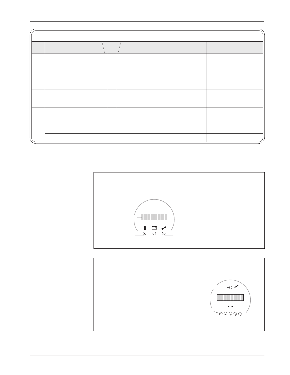
Curtis 1243GEN2 Manual
73
7 — DIAGNOSTICS & TROUBLESHOOTING
Table 7 TROUBLESHOOTING CHART,
cont’d
LED PROGRAMMER FAULT
CODE LCD DISPLAY
CATEGORY
POSSIBLE CAUSE FAULT CLEARANCE
4,1 LOW BATTERY VOLTAGE 2 1. Battery voltage < undervoltage cutback. When voltage rises above
2. Corroded battery terminal. undervoltage cutoff point.
3. Loose battery or controller terminal.
4,2 OVERVOLTAGE 2 1. Battery voltage >overvoltage shutdown. When voltage falls below
limit. overvoltage cutoff point.
2. Vehicle operating with charger attached.
4,3 THERMAL CUTBACK 2 1. Temperature >85°C or < -25°C. Clears when heatsink
2. Excessive load on vehicle. temperature returns to
3. Improper mounting of controller. within acceptable range.
4,4 ANTI-TIEDOWN 3 1. Mode switches shorted to B+. Release Mode Select 1.
2. Mode Select 1 “tied down” to select
Mode 2 or Mode 4 permanently.
MOTOR HOT 3 1. Field resistance > motor hot setpoint. When resistance < setpoint.
MOTOR WARM 3 1. Field resistance > motor warm setpoint. When resistance < setpoint.
Fig. 21 Curtis 840
Spyglass, 3-LED
and 6-LED models.
Fault LED (red)
BDI LED (yellow)
Hourmeter LED (green)
8-character LCD display
Fault LED (red)
BDI 0–100% LEDs
yellow
8-character LCD display
0 1
green
red
3-LED Spyglass
The hourmeter LED lights when the LCD
is displaying hourmeter data.
The BDI LED lights when the LCD is
displaying BDI%. It flashes when BDI%
drops to <10%.
The Fault LED flashes to indicate an
active fault, and the fault code appears on
the LCD.
The word SERVICE is displayed at key-on
if either service timer has expired.
6-LED Spyglass
The three green BDI LEDs function as a
bargraph showing BDI% between 52% and
100%.
Yellow LED = 36% – 51% BDI.
Red LED steady = 20% – 35% BDI.
Red LED flashing = 0 – 19% BDI.
The Fault LED flashes to indicate an
active fault, and the fault code appears on
the LCD.
The word SERVICE is displayed at key-on
if either service timer has expired.
Page 81
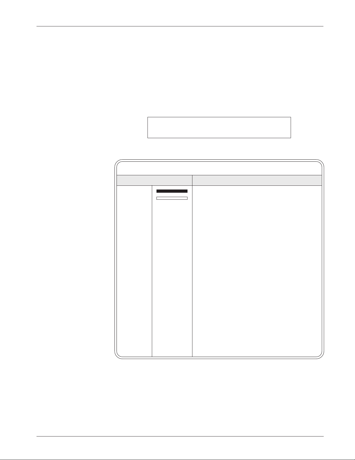
Curtis 1243GEN2 Manual
74
7 — DIAGNOSTICS & TROUBLESHOOTING
STATUS LED DIAGNOSTICS
A Status LED is built into the 1243GEN2 controller. It is visible through a
window in the label on top of the controller. This Status LED displays fault
codes when there is a problem with the controller or with the inputs to the
controller. During normal operation, with no faults present, the Status LED
flashes steadily on and off. If the controller detects a fault, a 2-digit fault
identification code is flashed continuously until the fault is corrected. For
example, code “3,2”—main contactor welded—appears as:
¤¤¤ ¤¤ ¤¤¤ ¤¤ ¤¤¤ ¤¤
( 3 , 2 ) ( 3 , 2 ) ( 3 , 2 )
The codes are listed in Table 8.
Table 8 STATUS LED FAULT CODES
LED CODES EXPLANATION
LED off no power or defective controller
solid on controller or microprocessor fault
0,1
■
¤ controller operational; no faults
1,1 ¤ ¤ current sensor error
1,2 ¤ ¤¤ hardware failsafe fault
1,3 ¤ ¤¤¤ M- fault or motor output short
1,4 ¤ ¤¤¤¤ static return to off (SRO)
2,1 ¤¤ ¤ throttle wiper high
2,2 ¤¤ ¤¤ emergency reverse circuit check fault
2,3 ¤¤ ¤¤¤ high pedal disable (HPD), or expired timer
2,4 ¤¤ ¤¤¤¤ throttle wiper low
3,1 ¤¤¤ ¤ contactor driver overcurrent or field winding short
3,2 ¤¤¤ ¤¤ main contactor welded
3,3 ¤¤¤ ¤¤¤ field winding open
3,4 ¤¤¤ ¤¤¤¤ missing contactor
4,1 ¤¤¤¤ ¤ low battery voltage
4,2 ¤¤¤¤ ¤¤ overvoltage
4,3 ¤¤¤¤ ¤¤¤ thermal cutback, due to over/under temp
4,4 ¤¤¤¤ ¤¤¤¤ anti-tiedown fault, or overheated motor
Note: Only one fault is indicated at a time, and faults are not queued up. Refer
to the troubleshooting chart (Table 7) for suggestions about possible causes of
the various faults. Operational faults—such as a fault in SRO sequencing—are
cleared by cycling the interlock switch or keyswitch.
Page 82

Curtis 1243GEN2 Manual
75
7 — DIAGNOSTICS & TROUBLESHOOTING
FAULT OUTPUT LED DIAGNOSTICS
The 1243GEN2 controller provides two fault outputs designed to transmit fault
information to LEDs located on the display panel or on any remote panel. These
outputs can be programmed to display faults in Fault Code format or in Fault
Category format—see Section 3, page 51.
In Fault Code format, the two fault outputs operate independently. The
Fault 1 line flashes the same codes, at the same time, as the controller’s built-in
Status LED (see Table 8). The Fault 2 line pulls low when a fault is present; it
can be used to drive an LED that simply indicates whether or not there is a fault.
When no faults are present, both of the fault lines are in their normal state
(high).
In Fault Category format, the two fault outputs together define one of
four fault categories, as listed in Table 9. When a fault occurs, the Fault 1 and
Fault 2 lines (Pins 2 and 3) go to the state indicating the category of the
particular fault: LOW/HIGH, HIGH/LOW, or LOW/LOW. When the fault is cleared,
the fault outputs return to their normal state (i.e., HIGH/HIGH).
Table 9 FAULT CATEGORY CODES
FAULT 1 FAULT 2 FAULT
OUTPUT OUTPUT CATEGORY POSSIBLE FAULT
HIGH HIGH 0 (no known faults)
LOW HIGH 1 Current shunt fault
Hardware failsafe fault
M- shorted
Throttle wiper high or low
Emergency reverse wiring fault
Field winding open
Contactor coil or field shorted
Main contactor welded or missing
HIGH LOW 2 Low battery voltage
Overvoltage
Thermal cutback, due to over/under temp
LOW LOW 3 Anti-tiedown fault
High pedal disable (HPD) fault
Static return to off (SRO) fault
Service timer or disable timer expired
Motor too hot
Page 83

Curtis 1243GEN2 Manual
76
8 — MAINTENANCE
8
CONTROLLER MAINTENANCE
There are no user serviceable parts in the Curtis 1243GEN2 controller. No
attempt should be made to open, repair, or otherwise modify the controller.
Doing so may damage the controller and will void the warranty.
It is recommended that the controller be kept clean and dry and that its
fault history file be checked and cleared periodically.
CLEANING
Periodically cleaning the controller exterior will help protect it against corrosion
and possible electrical control problems created by dirt, grime, and chemicals
that are part of the operating environment and that normally exist in battery
powered systems.
When working around any battery powered vehicle, proper safety precautions should be taken. These include, but are not limited to: proper training,
wearing eye protection, and avoiding loose clothing and jewelry.
Use the following cleaning procedure for routine maintenance.
1. Remove power by disconnecting the battery.
2. Discharge the capacitors in the controller by connecting a load
(such as a contactor coil or a horn) across the controller’s B+ and
B- terminals.
3. Remove any dirt or corrosion from the connector areas. The
controller should be wiped clean with a moist rag. Dry it before
reconnecting the battery. The controller should not be subjected
to pressured water flow from either a standard hose or a power
washer.
4. Make sure the connections are tight, but do not overtighten
them. See Section 2, page 7, for maximum tightening torque
specifications for the battery and motor connections.
FAULT HISTORY FILE
The handheld programmer can be used to access the controller’s fault history
file. The programmer will read out all the faults the controller has experienced
since the last time the history file was cleared. Faults such as contactor faults may
be the result of loose wires; contactor wiring should be carefully checked. Faults
such as overtemperature may be caused by operator habits or by overloading.
After a problem has been diagnosed and corrected, it is a good idea to
clear the fault history file. This allows the controller to accumulate a new file of
faults. By checking the new history file at a later date, you can readily determine
whether the problem was indeed fixed.
For instructions on accessing the history file, see Appendix B.
☞
C A U T I O N
Page 84

Curtis 1243GEN2 Manual
A-1
APPENDIX A: EMC & ESD DESIGN CONSIDERATIONS
APPENDIX A
VEHICLE DESIGN CONSIDERATIONS
REGARDING ELECTROMAGNETIC COMPATIBILITY (EMC)
AND ELECTROSTATIC DISCHARGE (ESD)
ELECTROMAGNETIC COMPATIBILITY (EMC)
Electromagnetic compatibility (EMC) encompasses two areas: emissions and
immunity. Emissions are radio frequency (rf ) energy generated by a product.
This energy has the potential to interfere with communications systems such as
radio, television, cellular phones, dispatching, aircraft, etc. Immunity is the
ability of a product to operate normally in the presence of rf energy.
EMC is ultimately a system design issue. Part of the EMC performance
is designed into or inherent in each component; another part is designed into
or inherent in end product characteristics such as shielding, wiring, and layout;
and, finally, a portion is a function of the interactions between all these parts.
The design techniques presented below can enhance EMC performance in
products that use Curtis motor controllers.
Decreasing Emissions
Motor brush arcing can be a significant source of rf emissions. These emissions
may be reduced by installing bypass capacitors across the motor wires and/or
between each motor wire and the motor frame. If the latter approach is used, the
voltage rating and leakage characteristics of the capacitors must be adequate to
meet any safety regulations regarding electrical connections between a battery
operated circuit and the chassis. The bypass capacitor should be installed as close
to the motor as possible, or even inside it, to provide the best performance.
Alternatively a ferrite bead can be installed on the wires, as close as possible to
the motor. In some instances, capacitors and ferrite beads may both be appropriate. Another option is to choose a motor with a brush material that will result
in less arcing to the commutator. Brushes that have been run in for approximately 100 hours will typically generate lower emissions than new brushes
because there is less arcing after they are properly seated.
The motor drive output from Curtis controllers can also make a contribution to rf emissions. This output is a pulse width modulated square wave with
rather fast rise and fall times that are rich in harmonics. The impact of these
switching waveforms can be minimized by making the wires from the controller
to the motor as short as possible. Ferrite beads installed on the drive wires can
further reduce these emissions. For applications requiring very low emissions,
the solution may involve enclosing the controller, interconnect wires, and
motor together in one shielded box. The motor drive harmonics can couple to
battery supply leads and throttle circuit wires, so ferrite beads may also be
required on these other wires in some applications.
Page 85

Curtis 1243GEN2 Manual
A-2
APPENDIX A: EMC & ESD DESIGN CONSIDERATIONS
Increasing Immunity
Immunity to radiated electric fields can be achieved either by reducing the
overall circuit sensitivity or by keeping the undesired signals away from this
circuitry. The controller circuitry itself cannot be made less sensitive, since it
must accurately detect and process low level signals from the throttle potentiometer. Thus immunity is generally achieved by preventing the external rf
energy from coupling into sensitive circuitry. This rf energy can get into the
controller circuitry via conducted paths and via radiated paths.
Conducted paths are created by the wires connected to the controller.
These wires act as antennas and the amount of rf energy coupled into these
wires is generally proportional to their length. The rf voltages and currents
induced in each wire are applied to the controller pin to which the wire is
connected. Curtis motor controllers include bypass capacitors on the printed
circuit board’s throttle wires to reduce the impact of this rf energy on the
internal circuitry. In some applications, ferrite beads may also be required on
the various wires to achieve desired performance levels.
Radiated paths are created when the controller circuitry is immersed in an
external field. This coupling can be reduced by enclosing the controller in a
metal box. Some Curtis motor controllers are enclosed by a heat sink that also
provides shielding around the controller circuitry, while others are unshielded.
In some applications, the vehicle designer will need to mount the controller
within a shielded box on the end product. The box may be constructed of just
about any metal, although steel and aluminum are most commonly used.
Most coated plastics do not provide good shielding because the coatings
are not true metals, but rather a mixture of small metal particles in a nonconductive binder. These relatively isolated particles may appear to be good
based on a dc resistance measurement but do not provide adequate electron
mobility to yield good shielding effectiveness. Electroless plating of plastic will
yield a true metal and can thus be effective as an rf shield, but it is usually more
expensive than the coatings.
A contiguous metal enclosure without any holes or seams, known as a
Faraday cage, provides the best shielding for the given material and frequency.
When a hole or holes are added, rf currents flowing on the outside surface of the
shield must take a longer path to get around the hole than if the surface was
contiguous. As more “bending” is required of these currents, more energy is
coupled to the inside surface, and thus the shielding effectiveness is reduced.
The reduction in shielding is a function of the longest linear dimension of a
hole rather than the area. This concept is often applied where ventilation is
necessary, in which case many small holes are preferable to a few larger ones.
Applying this same concept to seams or joints between adjacent pieces or
segments of a shielded enclosure, it is important to minimize the open length
of these seams. Seam length is the distance between points where good ohmic
contact is made. This contact can be provided by solder, welds, or pressure
contact. If pressure contact is used, attention must be paid to the corrosion
characteristics of the shield material and any corrosion-resistant processes
Page 86

Curtis 1243GEN2 Manual
A-3
APPENDIX A: EMC & ESD DESIGN CONSIDERATIONS
applied to the base material. If the ohmic contact itself is not continuous, the
shielding effectiveness can be maximized by making the joints between adjacent
pieces overlapping rather than abutted.
The shielding effectiveness of an enclosure is further reduced when a wire
passes through a hole in the enclosure. RF energy on the wire from an external
field is re-radiated into the interior of the enclosure. This coupling mechanism
can be reduced by filtering the wire at the point where it passes through the
boundary of the shield. Given the safety considerations involved with connecting electrical components to the chassis or frame in battery powered vehicles,
such filtering will usually consist of a series inductor (or ferrite bead) rather than
a shunt capacitor. If a capacitor is used, it must have a voltage rating and leakage
characteristics that will allow the end product to meet applicable safety regulations.
The B+ (and B-, if applicable) wires that supply power to the throttle
control panel—such as for the keyswitch—should be bundled with the remaining throttle wires so that all these wires are routed together. If the wires to the
control panel are routed separately, a larger loop area is formed. Larger loop
areas produce more efficient antennas which will result in decreased immunity
performance.
ELECTROSTATIC DISCHARGE (ESD)
Curtis motor controllers contain ESD-sensitive components, and it is therefore
necessary to protect them from ESD damage. Electrostatic discharge (ESD)
immunity is achieved either by providing sufficient distance between conductors and the outside world so that a discharge will not occur, or by providing an
intentional path for the discharge current such that the circuit is isolated from
the electric and magnetic fields produced by the discharge. In general the
guidelines presented above for increasing the radiated immunity will also
provide increased ESD immunity.
It is usually easier to prevent the discharge from occurring than to divert
the current path. A fundamental technique for ESD prevention is to provide
adequately thick insulation between all metal conductors and the outside
environment so that the voltage gradient does not exceed the threshold required
for a discharge to occur. If the current diversion approach is used, all exposed
metal components must be grounded. The shielded enclosure, if properly
grounded, can be used to divert the discharge current; it should be noted that
the location of holes and seams can have a significant impact on the ESD
suppression. If the enclosure is not grounded, the path of the discharge current
becomes more complex and less predictable, especially if holes and seams are
involved. Some experimentation may be required to optimize the selection and
placement of holes, wires, and grounding paths. Careful attention must be paid
to the control panel design so that it can tolerate a static discharge.
Page 87
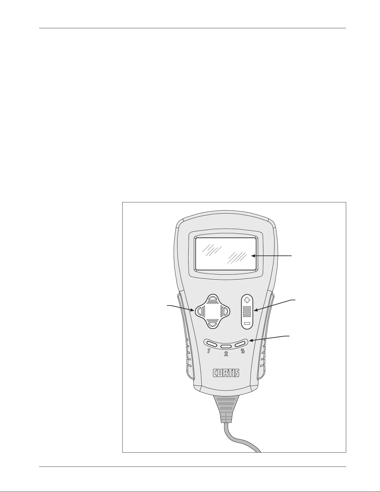
Curtis 1243GEN2 Manual
A-4
APPENDIX A: EMC & ESD DESIGN CONSIDERATIONS
B-1
APPENDIX B
CURTIS 1311 HANDHELD PROGRAMMER
The Curtis 1311 handheld programmer provides programming, diagnostic,
and test capabilities for the 1243GEN2 controller. The power for operating the
programmer is supplied by the host controller via a 4-pin Molex connector.
The programmer includes a 7-line alphanumeric LCD display, rockertype keys for navigating through the display and for modifying parameters (+/
-), and three keys that can be used as bookmarks.
The 1311 programmer is easy to use, with self-explanatory functions.
After plugging in the programmer, wait a few seconds for it to boot up and
gather information from the controller.
For experimenting with settings, the programmer can be left plugged in
while the vehicle is driven.
APPENDIX B: 1311 PROGRAMMER
Parameter
Modification Key
(to increase and
decrease values)
LCD Display
(seven lines,
alphanumeric)
Bookmark Keys
(for jumping easily back
and forth between fields)
Navigation Key
(to move around through
the programmer menus)
Fig. B-1 Curtis 1311
handheld programmer.
Page 88

Curtis 1243GEN2 Manual
A-5
APPENDIX A: EMC & ESD DESIGN CONSIDERATIONS
B-2
APPENDIX B: 1311 PROGRAMMER
The bookmark keys allow you to quickly go back to up to three selected
items without having to navigate back through the menu structure. To set a
bookmark, press one of the bookmark keys for about three seconds, until the
Bookmark Set screen is displayed. To jump to a set bookmark location, quickly
press the appropriate bookmark key (1, 2, or 3). Note that the bookmarks are
not permanently stored in the programmer. They are cleared when the programmer is unplugged.
The bookmark keys can be used to make parameter adjustment easier. For
example, in adjusting the throttle deadband, you might set a bookmark at the
Throttle % readout [Monitor > THROTTLE %] and another at the Throttle
Deadband parameter [Program > THROTTLE DB]; this way you can easily toggle
between the readout and the parameter.
1311 PROGRAMMER MENUS
There are six main menus, which in turn lead to nested submenus:
Program
— provides access to the individual programmable parameters (see
page 65).
Monitor
— presents real-time values during vehicle operation (see page 69).
Faults
— presents diagnostic information on active system faults (see page 70),
and also provides access to the fault history file and a means to clear the fault
history file.
Functions
— provides access to the controller-cloning commands (see page 52)
and to the “reset” command.
Information
— displays data about the host controller: model and serial numbers,
date of manufacture, hardware and software versions, and itemization of other
devices that may be associated with the controller’s operation.
Programmer Setup
— displays data about the programmer: model and serial
numbers, date of manufacture, hardware and software versions, and a list of the
programmable parameters that can be accessed with this particular programmer.
Page 89

Curtis 1243GEN2 Manual
A-6
APPENDIX A: EMC & ESD DESIGN CONSIDERATIONS
C-1
APPENDIX C: PROGRAMMABLE PARAMETERS INDEX
APPENDIX C
PROGRAMMABLE PARAMETERS INDEX
The 1243GEN2 controller’s programmable parameters are listed below in alphabetical order
(by programmer display name), with references provided to the main entry in the manual.
ACCEL RATE, M1-M4
page 21
ADJ HRS HIGH
page 45
ADJ HRS LOW
page 45
ADJ HRS MID
page 45
ANTI-TIEDOWN
page 41
AUX DELAY
page 28
AUX TYPE
page 28
BATTERY ADJUST
page 50
BDI DISABLE
page 50
BDI LIMIT SPD
page 50
BDI LOCKOUT
page 51
BRAKE C/L, M1-M4
page 23
BRAKE RATE, M1-M4
page 24
CONT DIAG
page 40
CREEP SPEED
page 31
CURRENT RATIO
page 22
DECEL RATE, M1-M4
page 23
DIS TOTL HRS
page 46
DIS TRAC HRS
page 46
DRIVE C/L, M1-M4
page 21
EM BRAKE PWM
page 28
EMPTY VOLTS
page 49
EMR DIR INTR
page 43
EMR REV CHECK
page 43
EMR REV C/L
page 43
FAULT CODE
page 51
FIELD CHECK
page 40
FIELD MAP
page 39
FIELD MAX
page 38
FIELD MIN
page 38
FLD MAP START
page 38
FULL VOLTS
page 49
HOURMETER TYPE
page 48
HPD
page 41
INT BRAKE DLY
page 28
INT BRAKE RATE
page 26
LOAD COMP
page 31
MAIN CONT INTR
page 40
MAIN OPEN DLY
page 40
MAX FWD REGEN
page 26
MAX FWD SPD, M1-M4
page 31
MAX LOAD VOLTS
page 27
MAX REV REGEN
page 26
MAX REV SPD, M1-M4
page 31
MIN FWD REGEN
page 27
MIN LOAD VOLTS
page 27
MIN REV REGEN
page 27
MOT WRM x10mΩ
page 44
MOT HOT x10mΩ
page 44
MOTOR Ω COMP
page 44
POT LOW FAULT
page 38
PUMP METER
page 48
QUICK START
page 21
RESET VOLTS
page 49
RESTRAINT, M1-M4
page 23
SEQUENCING DLY
page 42
SET TOTL HRS
page 45
SET TRAC HRS
page 46
SRO
page 42
SRVC TOTL
page 47
SRVC TOTL HRS
page 46
SRVC TRAC
page 47
SRVC TRAC HRS
page 46
TAPER RATE
page 25
THROTTLE DB
page 32
THROTTLE DECEL
page 23
THROTTLE MAP
page 36
THROTTLE MAX
page 34
THROTTLE TYPE
page 32
TRAC FAULT SPD
page 47
VARIABLE BRAKE
page 25
VOLTAGE
page 21
WARM SPEED
page 44
Page 90

Curtis 1243GEN2 Manual
A-1
APPENDIX A: EMC & ESD DESIGN CONSIDERATIONS
APPENDIX D
SPECIFICATIONS
NOMINAL DRIVE
ARMATURE FIELD
BRAKING
BATTERY CURRENT 2 MIN 1 HOUR 2 MIN 1 HOUR CURRENT
MODEL VOLTAGE LIMIT RATING RATING RATING RATING LIMIT
NUMBER
*
(volts) (amps) (amps) (amps) (amps) (amps) (amps)
1243-24XX 24 350 350 120 35 20 350
1243-42XX 24–36 200 200 80 25/35
†
15/20 200
1243-43XX 24–36 300 300 100 25/35
†
15/20 300
*
The last two digits of 1243GEN2 model numbers are 20 or higher:
1243-2401, 1243-4202, and 1243-4301 are 1243 controllers,
1243-24
20, 1243-4221, and 1243-4320 are 1243GEN2 controllers.
† The 1243-42XX and -43XX models are available as 25 amp or 35 amp models.
Table D-1 SPECIFICATIONS: 1243
GEN2 CONTROLLER
Nominal input voltage 24–36 V
PWM operating frequency 16 kHz
Electrical isolation to heatsink 500 V ac (minimum)
KSI input voltage (minimum) 16.8 V
KSI input current (no contactors engaged) 78 mA without programmer;
120 mA with 1311 programmer (110 mA with 1307)
Logic input voltage >7.5 V High; <1 V Low
Logic input current 15 mA
Operating ambient temperature range -40°C to 50°C (-40°F to 122°F)
Heatsink overtemperature cutback 85°C (185°F)
Heatsink undertemperature cutback -25°C (-13°F)
Overvoltage protection 24V models: cutback at approx. 30V, cutback at ≈34V
36V models: cutback at approx. 45V, cutback at ≈49V
Undervoltage protection 24V models: cutback at approx. 17V, cutback at ≈13V
36V models: cutback at approx. 25V, cutback at ≈21V
Package environmental rating IP53
Weight 1.45 kg (3.2 lb)
Dimensions (L × W × H) 198 × 114 × 70 mm (7.8" × 4.5" × 2.8")
Regulatory compliance Safety, applicable portions: EN 1175-1:1998
EMC and EMI: EN 12895:2000
UL Recognized Component, UL File AU1841
APPENDIX D: SPECIFICATIONS
D-1
 Loading...