

Page 1

Manual
Electronic Code Switch
Module (ECS)
» Software Device Profile 1.2.0.0 «
Curtis Instruments, Inc.
200 Kisco Avenue
Mt. Kisco, NY 10549
www.curtisinstruments.com
Read Instructions Carefully!
Specications are subject to change without notice.
© 2021 Curtis Instruments, Inc. ® Curtis is a registered trademark of Curtis Instruments, Inc.
© The design and appearance of the products depicted herein are the copyright of Curtis Instruments, Inc. 53241 RevA March 2021
Page 2

TABLE OF CONTENTS
CHAPTERS
1: OVERVIEW ......................................................................................................................................1
USING THIS MANUAL .................................................................................................................... 2
CONVENTIONS .............................................................................................................................. 2
NUMERAL SYSTEM NOTATION ................................................................................................ 2
MISCELLANEOUS CONVENTIONS ............................................................................................ 2
2: KEYPAD, LEDS, AND BUZZER .......................................................................................................... 3
KEYPAD ........................................................................................................................................ 3
LEDS ............................................................................................................................................ 3
BUZZER ........................................................................................................................................ 4
3: USER OPERATION ........................................................................................................................... 5
OPERATE A VEHICLE .....................................................................................................................5
USER MANAGEMENT MENU .......................................................................................................... 5
SPECIFY THE PIN CODE, TAG, AND/OR USER NAME CODE.............................................................. 6
4: INSTALLATION AND WIRING ............................................................................................................8
INSTALLING THE ECS .................................................................................................................... 8
I/O CONNECTOR ........................................................................................................................... 9
I/O PINS ....................................................................................................................................... 10
WIRING DIAGRAM ........................................................................................................................ 10
BATTERY CONNECTIONS .............................................................................................................. 11
PRECHARGE ................................................................................................................................ 11
RELAY OUTPUT ............................................................................................................................ 12
INTERLOCK .................................................................................................................................. 13
CANBus ....................................................................................................................................... 13
CALIBRATE THE ANTENNA............................................................................................................ 13
pg. ii
Curtis Electronic Code Switch Module (ECS) – March 2021
Page 3

TABLE OF CONTENTS cont’d
5: THE ECS SUPERVISOR AND USERS.................................................................................................14
USER STATUSES .......................................................................................................................... 14
6: PROGRAMMABLE PARAMETERS .................................................................................................... 15
LOGON USER MANAGEMENT MENU ............................................................................................. 17
LOGON USER SETUP MENU ......................................................................................................... 18
SUPERVISOR MANAGEMENT MENU .............................................................................................. 19
USER INFORMATION MENU .......................................................................................................... 20
REGISTERED USER LIST MENU .............................................................................................. 20
APPLICATION SETUP MENU ..........................................................................................................21
CONTROL MENU .................................................................................................................... 21
RELAY MENU ......................................................................................................................... 22
CAN INTERFACE MENU .......................................................................................................... 23
PDO SETUPS MENUS AND PDO MAPPING MENUS ..................................................................24
MISC MENU ........................................................................................................................... 27
PASS THROUGH MODE MENU ...................................................................................................... 28
7: SYSTEM MONITOR MENU ..............................................................................................................29
STATE MENU ...............................................................................................................................30
INPUTS MENU .............................................................................................................................. 31
SWITCH STATUS MENU ..........................................................................................................31
VOLTAGE MENU ..................................................................................................................... 31
FAULT HISTORY MENU ................................................................................................................. 32
8: DIAGNOSTICS AND FAULTS ............................................................................................................ 33
PROGRAMMING DEVICE DIAGNOSTICS ......................................................................................... 33
LEDS AND FAULT CODES ............................................................................................................. 34
FAULT RECORDS .......................................................................................................................... 34
FAULT CODES .............................................................................................................................. 35
Curtis Electronic Code Switch Module (ECS) – March 2021
pg. iii
Page 4

TABLE OF CONTENTS cont’d
9: CANOPEN COMMUNICATIONS ........................................................................................................ 37
BYTE AND BIT SEQUENCE ORDER ................................................................................................ 37
CAN PROGRAMMING CONSIDERATIONS ....................................................................................... 37
MESSAGE CAN-IDS ...................................................................................................................... 38
NMT STATE CONFIGURATION ....................................................................................................... 38
EMERGENCY MESSAGES AND FAULTS ......................................................................................... 38
EXPEDITED SDOS ........................................................................................................................ 39
PDOS ........................................................................................................................................... 40
PDO TIMING .......................................................................................................................... 40
PDO MAPPING OBJECTS ........................................................................................................ 40
PDO DATA BYTES .................................................................................................................. 41
MAP CAN OBJECTS TO A PDO ............................................................................................... 41
PDO1 .................................................................................................................................... 42
PDO2 .................................................................................................................................... 44
STANDARD CANOPEN OBJECTS ................................................................................................... 45
ERROR HISTORY OBJECT (1003H) ......................................................................................... 46
10: SUPERVISOR OPERATION WITH THE KEYPAD ................................................................................ 47
SUPERVISOR MANAGEMENT MENU .............................................................................................. 47
LOG ONTO THE SUPERVISOR MANAGEMENT MENU .....................................................................48
MANAGE THE SUPERVISOR’S PIN CODE, RFID TAG, AND USER NAME CODE ................................. 49
MANAGE USERS .......................................................................................................................... 50
USER STATUSES AND THE LEDS ............................................................................................ 50
ADD/DELETE USERS MENU ................................................................................................... 50
ADD AND DELETE PIN CODES, RFID TAGS, AND USERS .......................................................... 51
pg. iv
Curtis Electronic Code Switch Module (ECS) – March 2021
Page 5

TABLE OF CONTENTS cont’d
PROGRAM PARAMETERS WITH THE KEYPAD ................................................................................ 53
ACCESS THE PROGRAMMING MENU ...................................................................................... 53
CHANGE THE BAUD RATE PARAMETER .................................................................................. 54
CHANGE THE NODE ID PARAMETER ....................................................................................... 54
CHANGE THE INTERLOCK TYPE PARAMETER .......................................................................... 55
CHANGE THE LOGOFF TIME PARAMETER ............................................................................... 55
CHANGE THE MUTE ENABLE PARAMETER .............................................................................. 55
CHANGE THE RELAY WORK MODE PARAMETER .....................................................................56
SHOW THE LAST USER’S ID ......................................................................................................... 56
FIND THE FIRST AVAILABLE USER ID ............................................................................................ 57
CALIBRATE THE ANTENNA............................................................................................................ 57
11: MANAGE USERS WITH CURTIS PROGRAMMING DEVICES .............................................................. 58
USE THE SUPERVISOR MANAGEMENT MENU ...............................................................................58
USE THE LOGON USER SETUP MENU ...........................................................................................59
APPENDIX A: CURTIS PROGRAMMING DEVICES .................................................................................. 60
APPENDIX B: SPECIFICATIONS ........................................................................................................... 62
Curtis Electronic Code Switch Module (ECS) – March 2021
pg. v
Page 6

TABLE OF CONTENTS cont’d
FIGURES
FIGURE 1 MOUNTING DIMENSIONS ..................................................................................................... 8
FIGURE 2 WIRING DIAGRAM ............................................................................................................... 10
FIGURE 3 RELAY CONTACTS — MAXIMUM SWITCHING CURRENT ...................................................... 12
FIGURE 4 FAULT HISTORY DETAILS — CIT ......................................................................................... 32
FIGURE 5 FAULT HISTORY DETAILS — 1313 PROGRAMMER .............................................................. 32
FIGURE 6 ACTIVE FAULTS — CIT ........................................................................................................ 33
FIGURE 7 ACTIVE FAULTS — 1313 PROGRAMMER ............................................................................. 33
TABLES
TABLE 1 MATING CONNECTOR PARTS — IP40 PROTECTION ............................................................... 9
TABLE 2 MATING CONNECTOR PARTS — IP54 PROTECTION ............................................................... 9
TABLE 3 ECS PINS ............................................................................................................................. 10
TABLE 4 USER STATUSES .................................................................................................................. 14
TABLE 5 PDO SETUP MENUS .............................................................................................................24
TABLE 6 PDO MAPPING MENUS ......................................................................................................... 24
TABLE 7 PDO PARAMETERS’ CAN INDEXES AND DEFAULT VALUES ..................................................... 25
TABLE 8 FAULT CODES ......................................................................................................................35
TABLE 9 MAPPED PDO BYTES ...........................................................................................................40
pg. vi
Curtis Electronic Code Switch Module (ECS) – March 2021
Page 7

Return to TOC Curtis Electronic Code Switch Module (ECS) – March 2021
1 — OVERVIEW
e Curtis Electronic Code Switch (ECS) is an operator identication keypad. e ECS ensures
that only authorized users can operate a vehicle. e ECS supervisor denes the authorized users.
Authorized users can log on by entering a user ID and PIN code or by swiping an RFID tag.
e ECS can be integrated into vehicle systems with or without a CANbus. e ECS is designed for
use in applications such as material handling vehicles, MEWP (Mobile Elevating Work Platforms),
golf carts, ICE vehicles, and many others.
e following list summarizes the ECS’s key features:
• A Normally Open (NO) relay that is opened and closed by CAN messages or by users logging
on and o.
• Machine power control through authorized RFID tag and PIN code access or CAN commands.
• Easy to integrate with vehicle systems:
– CAN-based systems: CANopen implementation with an optionally connected CAN
termination resistor. Supports CAN baud rates from 100 Kbps to 1 Mbps.
– Non-CAN systems: e output relay changes state when an authorized user logs onto
the ECS.
• Pass-through mode, which is for applications in which another CAN device can receive
keypad entries and RFID tag swipes.
• Supports ISO 14443A RFID tags.
• Allows up to 100 users.
• Status LEDs and a buzzer conrm keypad entries and provide diagnostic information.
• Automatic log o based on the interlock state and a congurable timer.
• You can use the Curtis Integrated ToolkitTM (CIT) or the Curtis 1313 handheld programmer
to change parameters, monitor real-time data, review and clear the fault history, update
rmware, and perform other diagnostic and application development tasks.
• Operates in demanding conditions, with an operational temperature range of –40° to +70°C
and electronic components sealed to IP65.
• CE compliance, UL recognition, and ROHS 3 compliance ensure compatibility with global
regulatory safety.
Note: For technical support, contact the Curtis distributor or the Curtis sales and support oce in
your region.
1 — OVERVIEW
pg. 1
Page 8

Curtis Electronic Code Switch Module (ECS) – March 2021 Return to TOC
USING THIS MANUAL
• Vehicle operators only need to read the following chapters:
– Keypad, LEDs, and Buzzer
– User Operation
• e ECS supervisor should also read the following chapters:
– e ECS Supervisor and Users
– Supervisor Operation with the Keypad
– Manage Users with Curtis Programming Devices
• Users who install, congure, and troubleshoot the ECS should also read the chapters
applicable to their tasks.
CONVENTIONS
e following topics describes terms and notations used in this manual.
Numeral System Notation
e following table describes how this manual denotes decimal, binary, and hexadecimal numbers.
Note: e letter n in the Format column represents a digit.
Numeral System Format Example
Either of the following:
Decimal
Hexadecimal
Binary nnnb 101b
• nnn
• nnnd
Either of the following:
• nnnh
• 0xnnn
• 127
• 127d
• 62Ah
• 0x62A
In addition, some CANopen examples have hexadecimal values without notation. ose examples
are formatted with a monospace font and with the bytes delimited by spaces, as shown in the
following example:
21 FF 01 11 22 01 00 00
Miscellaneous Conventions
pg. 2
• RO means read-only.
• RW means read-write.
• N/A means not applicable.
• e word tag is used to describe RFID cards, keys, fobs, etc.
1 — OVERVIEW
Page 9
Return to TOC Curtis Electronic Code Switch Module (ECS) – March 2021
2 — KEYPAD, LEDs, AND BUZZER
e following topics describe the ECS’s keypad, LEDs, and buzzer.
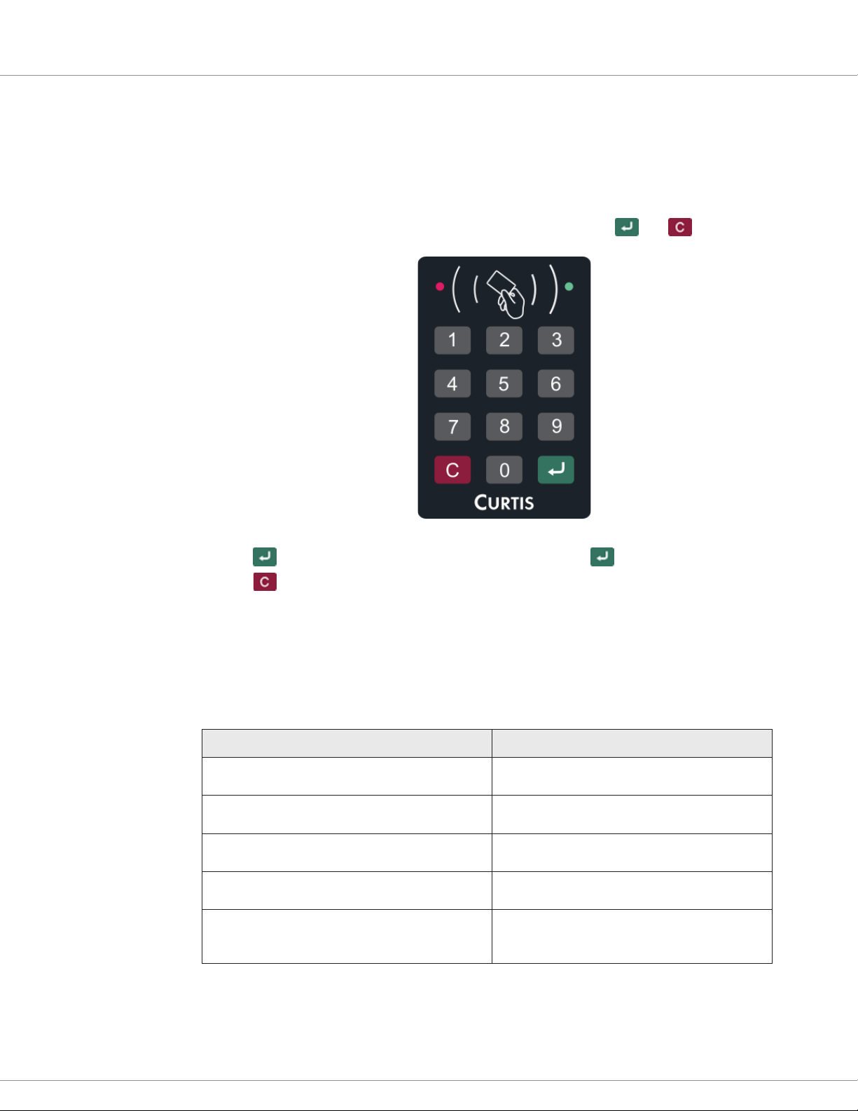
KEYPAD
e ECS keypad consists of buttons for the numbers 0–9, as well as and buttons:
• e button is used to submit entries. For example, press aer you enter a menu number.
• e button is used to perform various tasks such as logging on and o, clearing data, and
returning to the previous menu.
LEDs
e ECS has green and red LEDs that indicate information such as the current menu, status, and
fault codes. e following table summarizes the typical usages of the LEDs:
ECS Operation LEDs
The ECS is idle.
A user is logged on to operate the vehicle.
A fault occurs.
The supervisor is on the Supervisor Management
menu or a user is on the User Management menu.
The supervisor or a user is working with a submenu
of the Supervisor Management menu or User
Management menu.
The green LED ashes once per two seconds and
the red LED is off.
The red LED is off and the green LED remains on
without ashing.
The LEDs ash the fault code. Faults typically are
handled by a technician.
The red LED remains on without ashing and the
green LED is off.
The information indicated by the LEDs depends
upon the menu or submenu.
2 — KEYPAD, LEDs, AND BUZZER
pg. 3
Page 10
Curtis Electronic Code Switch Module (ECS) – March 2021 Return to TOC
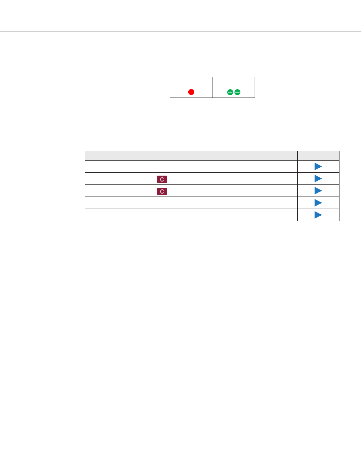
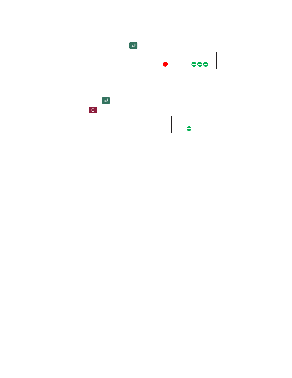
In this manual, LED ash sequences are described with tables that contain red and green circles.
When an LED periodically ashes, the number of ashes are indicated with striped circles. In the
following example, the red LED remains on without ashing and the green LED ashes twice per
two seconds:
Red Green
When an LED is o, the table will not include a circle for the LED.
BUZZER
e ECS has a buzzer that indicates whether user entries and RFID tag swipes are valid. e following
table describes the buzzer sounds.
Sound Description
Pushbutton You pressed a button.
Clear Data
Return
Error You entered invalid data or an invalid menu number.
Success You logged on, entered valid data, or pressed a valid menu number.
You pressed to clear data that you entered while working on a menu.
You pressed to return to the previous menu or to log off.
Play Audio
Note: If you don’t hear the buzzer, it means that the Mute Enable parameter is set to On.
pg. 4
2 — KEYPAD, LEDs, AND BUZZER
Page 11
Return to TOC Curtis Electronic Code Switch Module (ECS) – March 2021
3 — USER OPERATION
e ECS ensures that only authorized users can access a vehicle. If you are authorized, the ECS
supervisor will provide you with a user ID and PIN code, an RFID tag, or both.
e following sections describe how to use the ECS to operate a vehicle and to create or change your
tag, PIN code, and/or user name code.
OPERATE A VEHICLE
To operate a vehicle equipped with the ECS, log on by taking one of the following steps:
• Place your user tag in front of the ECS.
• Enter your user ID and PIN code, then press .
Note: If your user ID is 1–9, enter 0 before the digit. For example, if the user ID is User 3, enter 03.
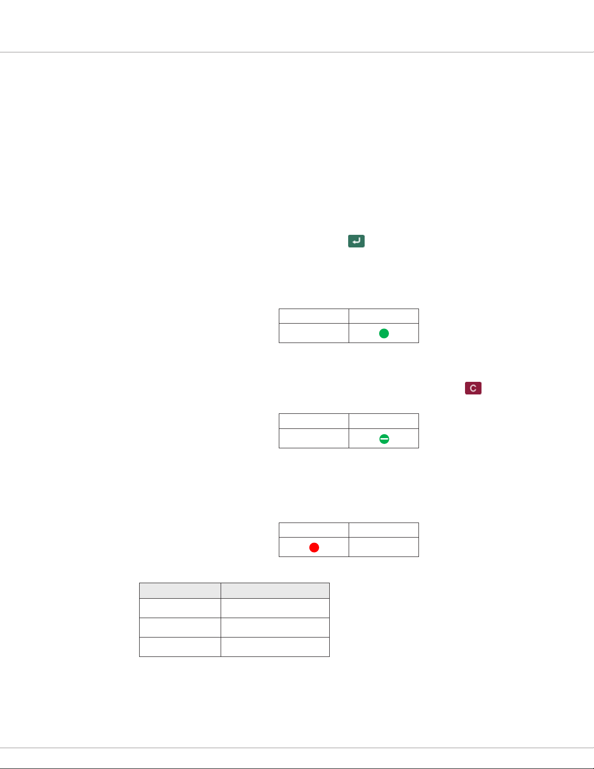
If your tag or your user ID and PIN code are valid, the buzzer sounds the Success sound and the
green LED remains on without ashing. You can now operate the vehicle.
Red Green
You remain logged on until you either log off, the interlock switch is off for longer than the
programmed timeout interval, or another operator swipes a tag.
Once you have nished operating the vehicle, log o by pressing and holding until you hear the
Return sound and the green LED starts ashing.
Red Green
USER MANAGEMENT MENU
e User Management menu allows you to add or change your PIN code, tag, and/or user name
code. When you are on the User Management menu, the red LED remains on without ashing and
the green LED is o.
Red Green
e User Management menu contains the following menus. To access a menu, press its menu number:
Menu Number Description
1 Change PIN code.
2 Change tag.
3 — USER OPERATION
3 Change user name code.
When you select a menu, the red LED remains on without ashing and the green LED ashes the
menu number every two seconds.
pg. 5
Page 12
Curtis Electronic Code Switch Module (ECS) – March 2021 Return to TOC
SPECIFY THE PIN CODE, TAG, AND/OR USER NAME CODE
Take the following steps to access the User Management menu and add or change your PIN code,
tag, and/or user name code.
Note: If the ECS doesn’t detect keypad activity for 60 seconds, the ECS automatically logs o.
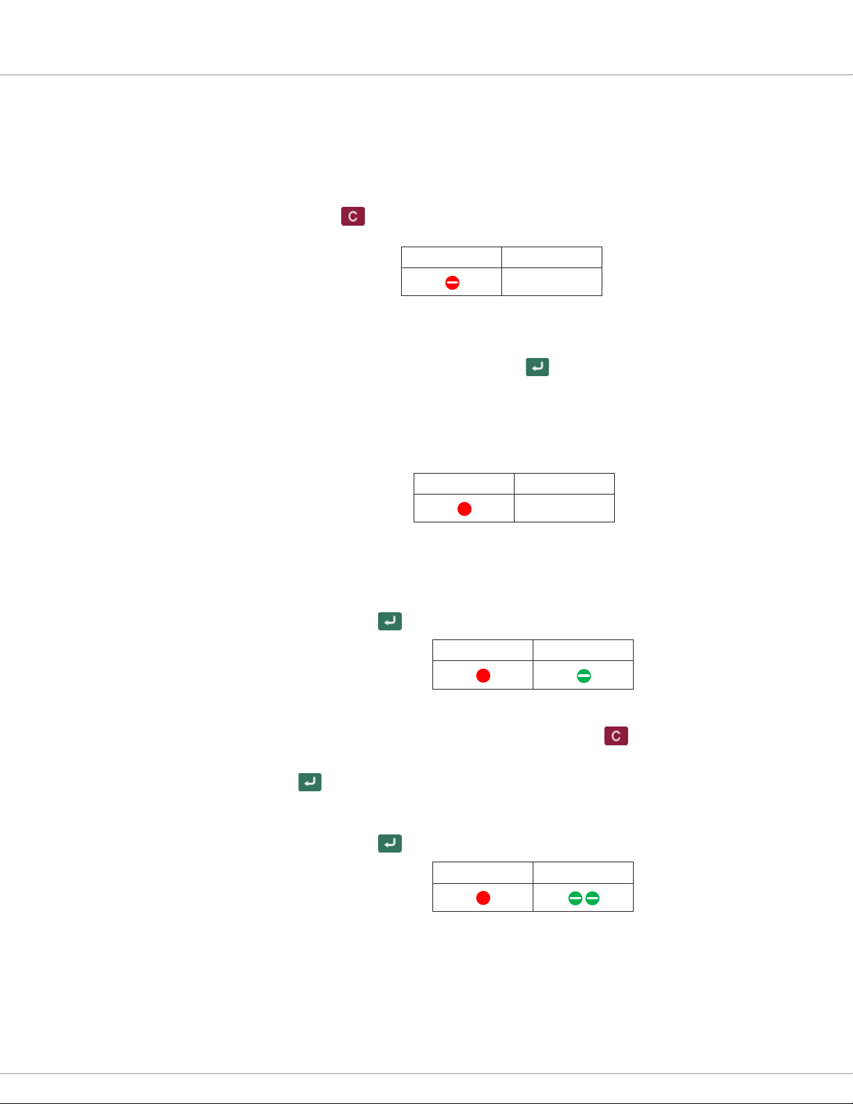
1. Press and hold the button for two seconds, until you hear the Pushbutton sound twice and
the red LED starts ashing.
Red Green
2. Perform one of the following steps:
– Place your user tag in front of the ECS.
– Enter your user ID and PIN code, then press .
Note: If your user ID is 1–9, enter 0 before the digit. For example, if the user ID is User 3,
enter 03.
The buzzer sounds the Success sound, indicating that you have accessed the User
Management menu.
Red Green
You can now perform any or all of the tasks listed in the following headings. e tasks can be
performed in any order:
Add or Change the PIN Code
a. Press 1, then press .
Red Green
b. Enter the PIN code, which must be between 2–6 digits.
Tip: If you need to clear the digits you’ve entered, press . You can then enter the new
PIN code.
c. Press to save the PIN code and return to the User Management menu.
Add or Replace the Tag
a. Press 2, then press .
Red Green
pg. 6
b. Place the tag in front of the ECS until you hear the Success sound. e ECS returns to the
User Management menu.
Note: Replacing a tag invalidates any tags previously created for the user ID.
3 — USER OPERATION
Page 13
Return to TOC Curtis Electronic Code Switch Module (ECS) – March 2021
Add or Change the User Name Code
a. Press 3, then press .
Red Green
b. Enter the user name code, which can be any number between 0–9999.
Note: e user name code is not your user ID, is not required, and is not used to log on to
the ECS. e user name code can be used for information such as an alias or an employee ID.
c. Press to save the user name code and return to the User Management menu.
3. Press to log o.
Red Green
3 — USER OPERATION
pg. 7
Page 14
Curtis Electronic Code Switch Module (ECS) – March 2021 Return to TOC
4 — INSTALLATION AND WIRING
This chapter explains how to install and wire the ECS and how to configure the inputs and
outputs (I/Os).
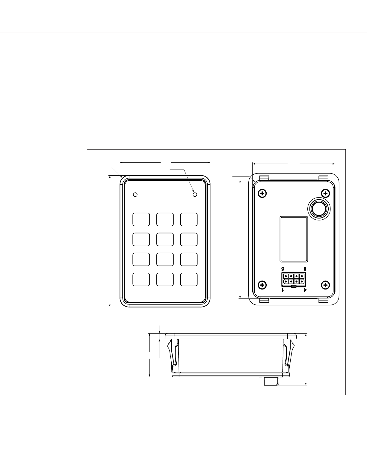
INSTALLING THE ECS
To install the ECS, snap-fit it into the desired location, using 2.0–4.0 mm snap-in fingers.
The location should be carefully chosen to keep the ECS clean and dry. Figure 1 shows the
mounting dimensions:
Figure 1
Mounting
Dimensions
4X R7
70.0
LED
2PLS
64.0
4X R5.5
102.0
34.0
4.3
92.0
40.0
pg. 8
Note: The panel hole size is 92.3 3 64.3 mm, with a tolerance of +0.7 mm for both the length
and width.
4 — INSTALLATION AND WIRING
Page 15
Return to TOC Curtis Electronic Code Switch Module (ECS) – March 2021
I/O CONNECTOR
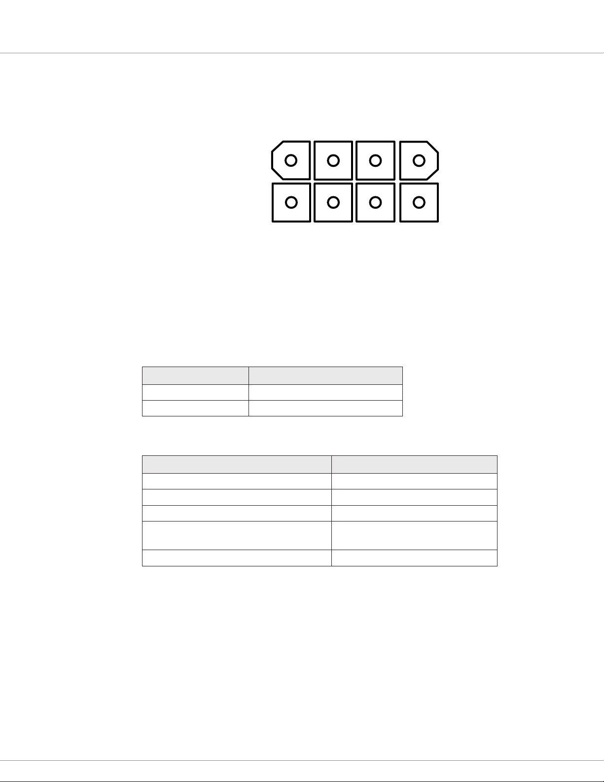
e ECS provides an 8-pin connector for the I/Os.
14
8
5
e mating connector is an 8-pin Mini-Universal MATE-N-LOK housing plug from TE Connectivity.
e front of the ECS is sealed to IP65. e rear of the ECS is sealed to IP65 for electronic components
and to IP40 for the connector. You can increase the connector’s protection to IP54 by using the parts
listed in Table 2.
e following tables list the TE Connectivity parts for IP40 and IP54 protection.
Table 1 Mating Connector Parts — IP40 Protection
Part TE Connectivity Part Number
Connector Housing 770579-1
Terminal (18–22 AWG) 770904-X
Table 2 Mating Connector Parts — IP54 Protection
Part TE Connectivity Part Number
Connector Housing 794821-1
Terminal (18–22 AWG) 770904-X
Interface Seal 794772-8
Single Wire Seal or Gang Seal • Single: 794758-1
• Gang: 1586359-8
Cavity Plug Seal (for unused terminal positions) 794995-1
4 — INSTALLATION AND WIRING
pg. 9
Page 16
Curtis Electronic Code Switch Module (ECS) – March 2021 Return to TOC
120Ω CAN BUS TERMINATION
KEYSWITCH
I/O PINS
e following table describes the I/O pins.
Table 3 ECS Pins
Pin Signal Name Description
Figure 2
Wiring Diagram
J1-1 CAN Term
CAN terminating 120Ω resistor.
Note: To enable the resistor, connect this pin to pin J1-6.
J1-2 Interlock Input Active high; 12–96V
J1-3 Relay COM Power to relay; 12– 96V
J1-4 Relay NO Relay output
J1-5 CAN Low
J1-6 CAN High
J1-7 B+ Battery Positive
J1-8 B– Battery Common
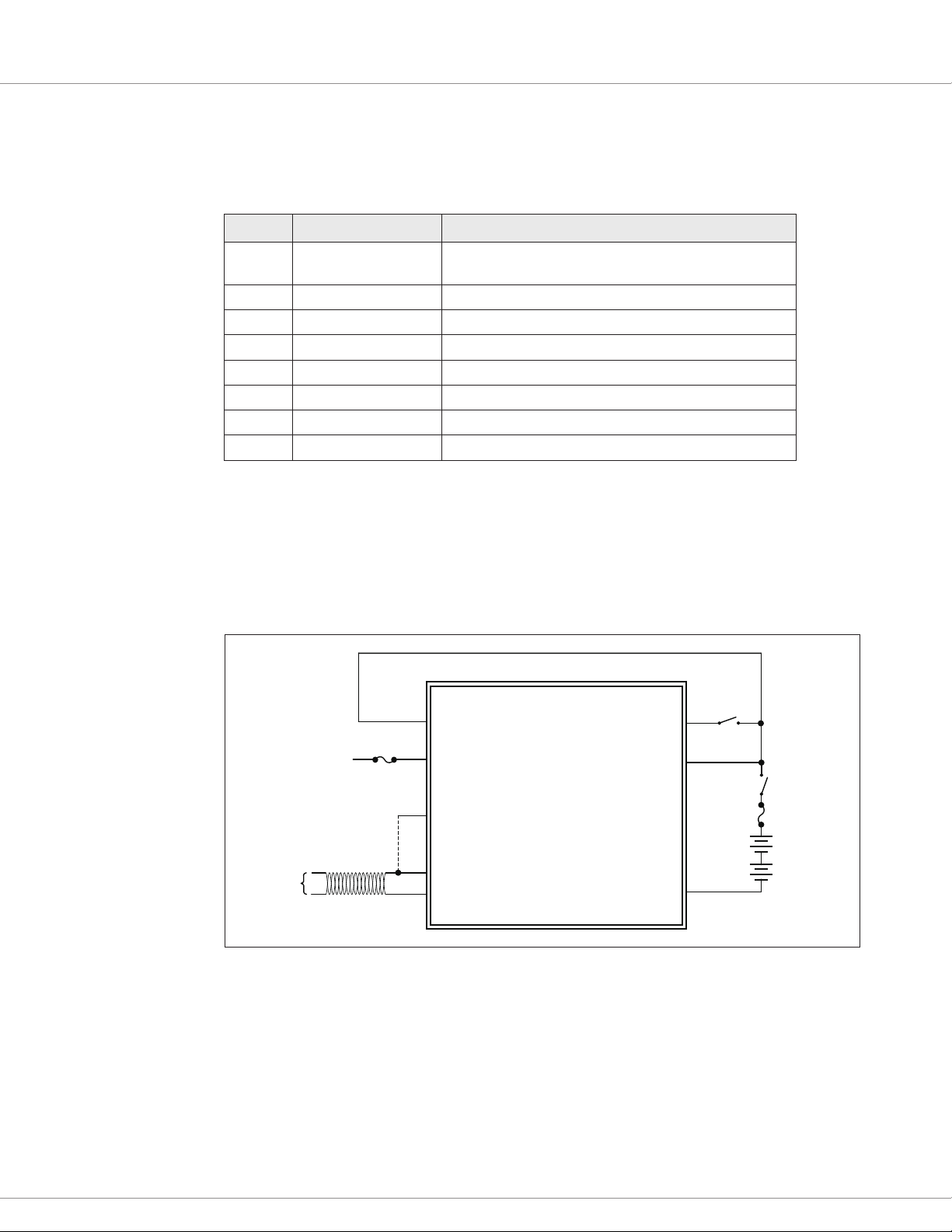
WIRING DIAGRAM
The following diagram illustrates a configuration in which the ECS is connected to an
interlock switch.
J1-3
RELAY COM INTERLOCK INPUT
FUSE
CONNECTED
TO LOAD
CONNECT J1-1 TO J1-6 FOR
CAN
PORT
J1-4
J1-1
J1-6
J1-5
RELAY N.O.
CAN TERM
CAN HIGH
CAN LOW
Note: Use fuses that are appropriately sized for your application.
B+
J1-2
J1-7
FUSE
BATTERY
(12-96V)
J1-8
B-
pg. 10
4 — INSTALLATION AND WIRING
Page 17
Return to TOC Curtis Electronic Code Switch Module (ECS) – March 2021
Current Limit (A)
Relay COM Voltage
BATTERY CONNECTIONS
Connect the battery to the B+ and B– pins (pins 7–8, respectively). e following table describes the
B+ pin’s operating voltage:
Minimum Nominal Maximum
9VDC 12–96VDC 120VDC
Note: All voltages listed in this manual are DC voltages.
e following table describes the B+ pin’s operating current:
B+ Voltage Operating Current
12V 248mA
24V 114mA
36V 70mA
48V 52mA
60V 44mA
72V 37mA
80V 32mA
96V 33mA
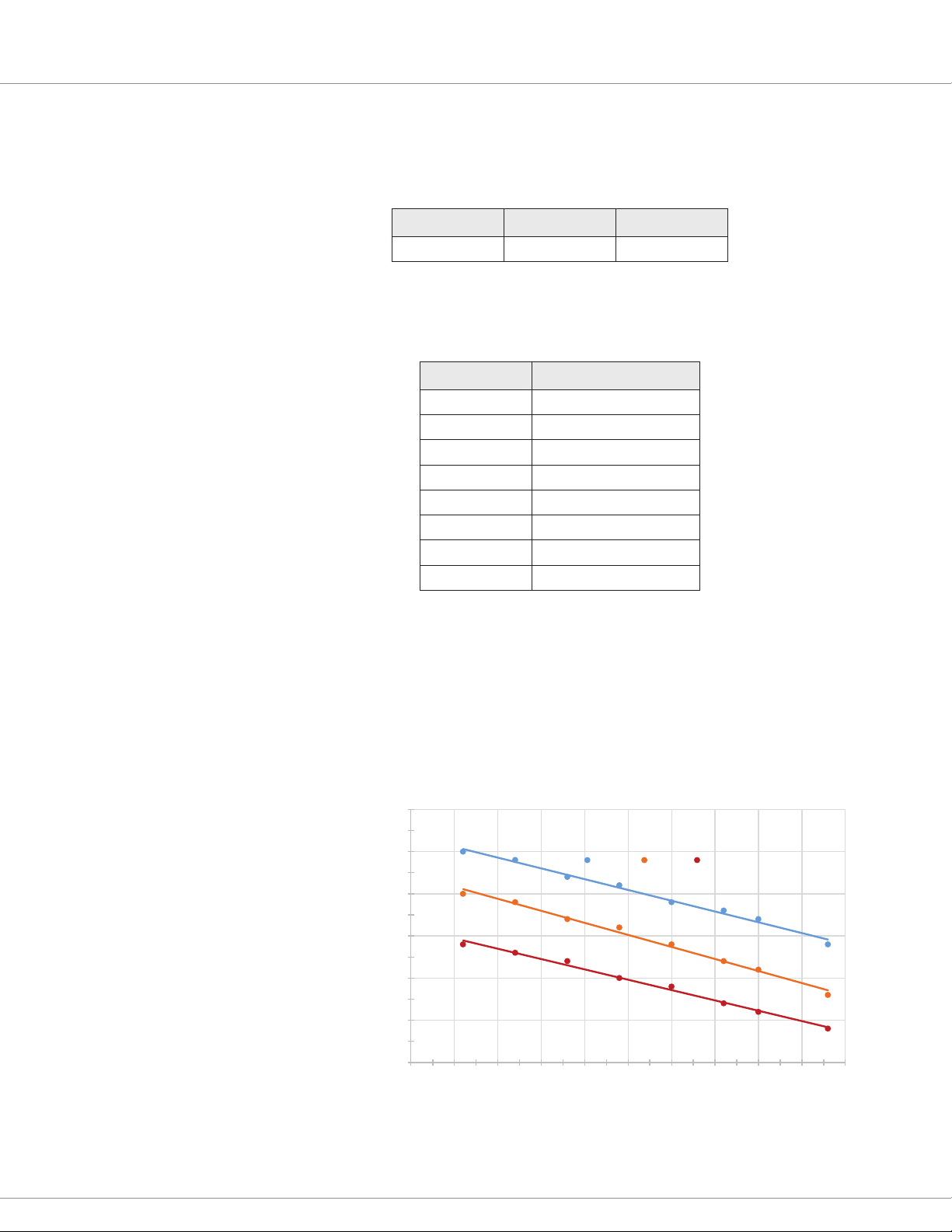
PRECHARGE
To suppress arcing across the relay contacts when the relay closes, the ECS uses a current-limited
precharge circuit to power the devices connected to Relay NO. e relay closes when the Relay NO
voltage reaches 90% of the Relay COM voltage; if the relay doesn’t close, a Precharge Fault occurs.
The following chart shows the precharge current limits for Relay COM voltages at various
ambient temperatures:
3 .0
2 .5
2 .0
Precharge
1 .5
1 .0
0 .5
0 .0
0 10 20 30 40 50 60 70 80 90 100
-4 0°C 2 5 °C 7 0°C
4 — INSTALLATION AND WIRING
pg. 11
Page 18

Curtis Electronic Code Switch Module (ECS) – March 2021 Return to TOC
Contact Current (A)
200
Contact Voltage (V)
RELAY OUTPUT
e ECS uses a normally open (NO) relay as an output driver. When the relay engages, Relay NO
(pin 4) outputs the power provided by the power source. Connect Relay COM (pin 3) in series with
the power source, and connect Relay NO to the load.
e following table describes the Relay COM operating voltage:
Nominal Minimum Maximum
12–96V 9V 120V
e following table and Figure 3 describe the maximum switching current for various voltages when
a resistive load is connected:
Contact Voltage Maximum Switching Current
12V 16.0A
24V 16.0A
36V 1.5A
48V 0.9A
60V 0.7A
72V 0.6A
80V 0.5A
96V 0.3A
120V 0.3A
pg. 12
Figure 3
Relay Contacts — Maximum
Switching Current
1005040302010
4 — INSTALLATION AND WIRING
Page 19

Return to TOC Curtis Electronic Code Switch Module (ECS) – March 2021
When the ECS commands the relay to close or open, the Relay State parameter indicates the
relay’s state:
• When the relay closes, the Relay State value changes in this order: 0, 1, 2, 3, 4, 5.
• When the relay opens, the Relay State value changes in this order: 5, 6, 8, 0.
e Relay Work Mode parameter species whether logging on or CAN commands engage the relay.
ere also are parameters for conguring the relay’s pull-in and holding voltages; see Relay Menu.
INTERLOCK
When the interlock state is o and the logo interval has expired, the ECS automatically logs the
user o. e logo interval is specied with the Logo Time parameter.
Note: e automatic logo can be disabled by setting Logo Time to 0.
e interlock signal can be controlled with either a switch, such as a seat switch, or RPDO1. e
Interlock Type parameter species the interlock signal’s source.
If the vehicle uses an interlock switch, connect the switch to pin 2. When a switch is used, the
interlock’s input voltage ranges from 0V to the B+ voltage. e interlock input is active high; the
interlock state is o when the interlock input’s voltage is below the voltage specied with the Interlock
High reshold parameter.
Note: For information on the interlock parameters, see Control Menu.
CANbus
To connect the ECS to the CANbus, connect CAN Low and CAN High to pins 5 and 6, respectively.
Use twisted-pair wiring to minimize the likelihood of picking up a voltage bias on only one signal.
Pin 1 provides access to an internal 120Ω terminating resistor. To enable the resistor, connect CAN
High (pin 6) to pin 1.
e ECS includes parameters for items such as the baud rate, heartbeat rate, node ID, and PDOs. For
more information, see CAN Interface Menu and CANopen Communications.
CALIBRATE THE ANTENNA
Aer the ECS is installed, calibrate the antenna so that the ECS automatically detects the best channel
for RFID recognition. You can calibrate with either of the following:
• e AM Base Calibration parameter.
• e keypad; see the Calibrate the Antenna section.
4 — INSTALLATION AND WIRING
pg. 13
Page 20

Curtis Electronic Code Switch Module (ECS) – March 2021 Return to TOC
5 — THE ECS SUPERVISOR AND USERS
e ECS supervisor is responsible for authorizing users to log on to the ECS. e supervisor authorizes
users by creating PIN codes and/or tags for user IDs. Aer the supervisor creates a user, the user can
log onto the ECS by swiping the tag or entering the user ID and PIN code.
e supervisor can delete users. When a user is deleted, the user’s PIN code and/or RFID tag are
deactivated and the user can no longer log on to the ECS.
e ECS provides 100 user IDs. e supervisor’s user ID is 00. e remaining user IDs, which range
from 01 through 99, are for users.
The default supervisor PIN code is 123456. For security reasons, change the supervisor’s PIN code
CAUTION
as soon as possible.
e following considerations apply to supervising users:
• e default PIN code for users is 1234. Aer the supervisor creates a PIN code for a user ID,
the user should specify a dierent PIN code.
• Aer the supervisor creates a tag for a user ID, the user can create a PIN code.
• Aer the supervisor creates a PIN code for a user ID, the user can create a tag.
• e supervisor can remove a user’s tag while preserving the user’s PIN code, and vice versa.
• e supervisor logs on with the ECS keypad.
• e supervisor manages users with the keypad or with a Curtis programming device, as
described in the following topics:
– Supervisor Operation with the Keypad
– Manage Users with Curtis Programming Devices
Note: e supervisor can also use the keypad to update some parameters and calibrate the
antenna eld strength level.
USER STATUSES
Each user ID has a user status. e user status indicates whether and how the user can access the
ECS. User statuses are identied by numbers and are described in the following table:
Table 4 User Statuses
User Status Description
1 The user is not authorized to access the ECS.
2 The user only has a PIN code.
3 The user only has a tag.
4 The user has both a PIN code and a user tag.
pg. 14
5 — THE ECS SUPERVISOR AND USERS
Page 21

Return to TOC Curtis Electronic Code Switch Module (ECS) – March 2021
6 — PROGRAMMABLE PARAMETERS
LOGON USER MANAGEMENT MENU..... p.1 7
— Logon User ID
— Logon User Name Code
— Logon RFID 1
— Logon RFID 2
— Logon RFID 3
LOG ON USER SETUP MENU......... p.18
— New PIN Code
— Save New PIN Code
— New RFID Tag
— Delete RFID Tag
— New Name Code
— Save New Name Code
SUPERVISOR MANAGEMENT MENU..... p.19
— First Free User ID
— Target User ID
— Target User State
— Create Target User PIN Code
— Create Target User RFID Tag
— Delete Target User
USER INFORMATION MENU............... p.20
— Last Logon User ID
— Total Registered Users
REGISTERED USER LIST MENU.... p.20
SUPERVISOR MENU................ p.20
— User Status
— User Name Code
USER 01—USER 99 MENUS... p.20
— User Status
— User Name Code
APPLICATION SETUP MENU............... p.21
CONTROL MENU........................... p.21
— Interlock Type
— Interlock High Threshold
— Mute Enable
— Logoff Time
RELAY MENU................................ p.22
— Relay Work Mode
— Pull-in Voltage
— Holding Voltage
— Open Delay
— Relay Driver
— Relay Driver PWM
— Relay Driver Feedback
CAN INTERFACE MENU................. p.23
— Baud Rate
— Node ID
— Heartbeat Rate
— Auto Operation
— CAN NMT State
RPDO1—RPDO4 SETUPS MENUS.... p.24
— RPDOn Event Time
— RPDOn COB ID
RPD O1—RPDO4 SETUPS
MENUS.............................. p.24
— Length
— Map 1 through Map 8
TPDO1—TPDO4 SETUPS MENUS.... p.24
— TPDOn Event Time
— TPDOn COB ID
TPD O1—TPDO4 MAPPING
MENUS.............................. p.24
— Length
— Map 1 through Map 8
MISC MENU.................................. p.27
— Restore Parameters
— AM Base Calibration
— Pass Through Switch
PASS THROUGH MODE MENU........... p.28
— Input PushButton Value
— Clear PushButton Value
— RFID 0
— RFID 1
— RFID 2
6 — PROGRAMMABLE PARAMETERS
pg. 15
Page 22

Curtis Electronic Code Switch Module (ECS) – March 2021 Return to TOC
The programmable parameters allow you to configure the ECS so that it meets your application’s
requirements. Curtis programming devices provide a user-friendly way to read and write to
the parameters.
Note: You can change some parameters with the keypad; see Program Parameters with the Keypad.
Restart the ECS after you change a parameter marked as [PCF]. If the ECS is not restarted, a
Parameter Change fault will occur.
e parameters are grouped into menus and are described in the following topics. e following
columns in the parameter description tables contain multiple types of information:
• Parameter and CAN Index: e parameter name, followed by the CAN index and sub-index.
is column also identies parameters marked as [PCF].
Note: CAN indexes and sub-indexes are delimited by colons. For example, a parameter with
an index of 0x4E46 and a sub-index of 0x00 would be represented as 0x4E46:00.
• Val ue s and Raw Values: e allowed values as displayed in Curtis programming devices,
followed by allowed values in raw units suitable for CAN messages.
• Data Size and Read/Write. e parameter’s data size, followed by whether the parameter is
writable (RW) or read-only (RO).
• Access Level and Default Value. e parameter’s access level for Curtis programming devices,
followed by the default value.
Note: Curtis programming device licenses provide dierent access levels to parameters.
pg. 16
6 — PROGRAMMABLE PARAMETERS
Page 23

Return to TOC Curtis Electronic Code Switch Module (ECS) – March 2021
LOGON USER MANAGEMENT MENU
e Logon User Management parameters indicate information about the logged-on user. e Logon
User Management menu also contains the Logon User Setup menu.
Note: e Logon RFID 1, Logon RFID 2, and Logon RFID 3 parameters cannot be accessed through
the CANbus.
LOGON USER MANAGEMENT MENU
PARAMETER
CAN INDEX
Logon User ID
0x3804:00
Logon User Name Code
0x3805:00
Logon RFID 1 0–4294967295
Logon RFID 2 0–4294967295
Logon RFID 3 0–4294967295
VALUES
RAW VALUES
–1 to +99
–1 to +99
0–99999
0–99999
0–4294967295
0–4294967295
0–4294967295
DATA SIZE
READ/WRITE ACCESS LEVEL DESCRIPTION
8-bit
RO
32-bit
RO
32-bit
RO
32-bit
RO
32-bit
RO
Field Basic Indicates the user ID of the logged-on user.
Note: –1 indicates that no one is logged on. The
supervisor user ID is 0.
Field Basic Indicates the user name code of the logged-on user.
Field Basic Indicates the rst four bytes of the UID of the logged-
on user’s RFID tag.
Field Basic Indicates the second set of bytes of the RFID tag's
UID. The value depends upon the tag’s cascade level:
• Cascade level 2: Three bytes
• Cascade level 3: Four bytes
Field Basic For cascade level 3 tags, indicates the last two bytes
of the RFID tag's UID.
6 — PROGRAMMABLE PARAMETERS
pg. 17
Page 24

Curtis Electronic Code Switch Module (ECS) – March 2021 Return to TOC
LOGON USER SETUP MENU
e following table describes the Logon User Setup menu. e parameters let the logged-on user
create or change the user’s PIN code, RFID tag, and user name code.
e Logon User Setup Menu is visible only when the supervisor is logged on to manage users or the
vehicle operator is logged on to manage the user’s credentials. In addition, the menu’s parameters
can be accessed through the CANbus only if the supervisor or vehicle operator is logged on.
LOGON USER SETUP MENU
PARAMETER
CAN INDEX
New PIN Code
0x3828:00
Save New PIN Code
0x3829:00
New RFID Tag
0x3827:00
Delete RFID Tag
0x382C:00
New Name Code
0x382A:00
Save New Name Code
0x382B:00
VALUES
RAW VALUES
0–999999999
0–999999999
Off/On
0–1
Off/On
0–1
Off/On
0–1
0–99999
0–99999
Off/On
0–1
DATA SIZE
READ/WRITE ACCESS LEVEL DESCRIPTION
32-bit
RW
8-bit
RW
8-bit
RW
8-bit
RW
32-bit
RW
32-bit
RW
Field Basic Indicates a new PIN code for the logged-on user.
Specify 9 as a control word, followed by the PIN code.
For example, if the PIN code is 3579, specify 93579.
The new PIN code is activated by setting the Save
New PIN Code parameter to On.
Field Basic Activates the New PIN Code.
Field Basic Adds or changes an RFID tag for the logged-on user.
To add the tag, set the parameter to On, then place
the tag in front of the ECS until the buzzer sounds
the Success sound.
Field Basic Deletes the RFID tag of the logged-on user. To delete,
set the parameter to On.
Field Basic Indicates a new user name code. Specify 9 as a control
word, followed by the user name code. For example, if
the user name code is 2468, specify 92468.
The new user name code is activated by setting the
Save New Name Code parameter to On
Field Basic Activates the New Name Code.
pg. 18
6 — PROGRAMMABLE PARAMETERS
Page 25

Return to TOC Curtis Electronic Code Switch Module (ECS) – March 2021
SUPERVISOR MANAGEMENT MENU
e Supervisor Management menu allows the supervisor to add and delete authorized users. is
menu is visible when the supervisor has logged on to manage users.
Note: e First Free User ID parameter cannot be accessed through the CANbus. Data for the other
parameters can be downloaded and uploaded only when the supervisor is logged on to manage users.
Adding a user involves creating an RFID tag and/or a PIN code for a user ID. When a PIN code or
an RFID tag is added or a user is deleted, the buzzer sounds the Success sound. For steps on using
this menu, see Use the Supervisor Management Menu.
e following table describes the Supervisor Management parameters.
SUPERVISOR MANAGEMENT MENU
PARAMETER
CAN INDEX
First Free User ID 0–99
Target User ID
0x3830:00
Target User State
0x3831:00
Create Target User
PIN Code
0x3833:00
Create Target User
RFID Tag
0x3832:00
Delete Target User
0x3834:00
VALUES
RAW VALUES
0–99
1–99
1–99
1–5
1–5
Off/On
0–1
Off/On
0–1
Off/On
0–1
DATA SIZE
READ/WRITE ACCESS LEVEL DESCRIPTION
8-bit
RO
8-bit
RW
8-bit
RO
8-bit
RW
8-bit
RW
8-bit
RW
Field Basic Indicates the rst user ID for which neither a PIN Code
nor a user tag has been added.
Field Basic Species the user ID to be managed.
Field Basic Indicates the user status of the Target User ID.
1 = The user is not authorized to access the ECS.
2 = The user only has a PIN Code.
3 = The user only has an RFID tag.
4 = The user has both a PIN Code and an RFID tag.
5 = An error has occurred.
Field Basic Activates the PIN code for the Target User ID. To
activate, set the parameter to On.
The default PIN code is 1234. It’s recommended that
the user change the PIN code.
If the supervisor attempts to create a new PIN code
for a Target User ID that already has a PIN code, the
buzzer will sound the Error sound. To create a new
PIN code, delete the user, then create a PIN code for
the same user ID.
Field Basic Activates the RFID tag for the Target User ID. To
activate, set the parameter to On, then place the
tag in front of the ECS until the buzzer sounds the
Success sound.
If the supervisor attempts to create a new tag for a
Target User ID that already has a tag, the buzzer will
sound the Error sound. To create a new tag, delete
the user, then create a tag for the same user ID.
Field Basic Deletes the Target User ID. To delete, set the
parameter to On.
6 — PROGRAMMABLE PARAMETERS
pg. 19
Page 26

Curtis Electronic Code Switch Module (ECS) – March 2021 Return to TOC
USER INFORMATION MENU
e following table describes the User Information parameters. e menu also contains the Registered
User List menu.
Note: e User Information parameters cannot be accessed through the CANbus.
USER INFORMATION MENU
PARAMETER
CAN INDEX
Last Logon User ID 0–99
Total Registered Users 0–100
VALUES
RAW VALUES
0–99
0–100
Registered User List Menu
e Registered User List menu contains the Supervisor menu and the User 01–99 menus, which are
described in the following topics.
Supervisor Menu
e following table describes the parameters on the Supervisor menu. e supervisor’s user ID is 00.
Note: e Supervisor menu parameters cannot be accessed through the CANbus.
USER INFORMATION MENU — SUPERVISOR MENU
PARAMETER
CAN INDEX
User Status 1–5
User Name Code 0–99999
VALUES
RAW VALUES
1–5
0–99999
DATA SIZE
READ/WRITE ACCESS LEVEL DESCRIPTION
8-bit
RO
8-bit
RO
Field Basic Indicates the user ID of the last user to log onto
the ECS.
OEM Dealer Indicates the number of registered users.
DATA SIZE
READ/WRITE ACCESS LEVEL DESCRIPTION
8-bit
RO
32-bit
RO
Field Basic Indicates the supervisor’s user status. The user
statuses are represented by the same values as the
Target User State parameter’s allowed values.
Field Basic Indicates the supervisor’s user name code.
pg. 20
User 01–99 Menus
Each user ID has a User n menu, where n represents the user ID. The User n menus contain
parameters with the same names, allowed values, data sizes, descriptions, etc. e following table
describes the User n menu parameters.
Note: e User n menu parameters cannot be accessed through the CANbus.
USER INFORMATION MENU — USER 01–99 MENUS
PARAMETER
CAN INDEX
User Status 1–5
User Name Code 0–99999
VALUES
RAW VALUES
1–5
0–99999
DATA SIZE
READ/WRITE ACCESS LEVEL DESCRIPTION
8-bit
RO
32-bit
RO
Field Basic Indicates the user’s status. The user statuses are
represented by the same values as the Target User
State parameter’s allowed values.
Field Basic Indicates the user name code.
6 — PROGRAMMABLE PARAMETERS
Page 27

Return to TOC Curtis Electronic Code Switch Module (ECS) – March 2021
APPLICATION SETUP MENU
e Application Setup menu contains the following menus:
• Control menu
• Relay menu
• CAN Interface menu
• Misc menu
ese menus are used to congure the ECS, and are described in the following topics.
Control Menu
e following table describes the parameters on the Control menu.
APPLICATION SETUP MENU — CONTROL MENU
PARAMETER
CAN INDEX
Interlock Type
0x3705:00
Interlock High Threshold
0x3323:00
Mute Enable
0x3701:00
Logoff Time
0x3702:00
VALUES
RAW VALUES
0–1
0–1
2.00–30.00V
200–3000
Off/On
0–1
0–255
0–255 min
DATA SIZE
READ/WRITE
8-bit
RW
16-bit
RW
8-bit
RW
8-bit
RW
ACCESS LEVEL
DEFAULT VALUE DESCRIPTION
OEM Dealer0Indicates whether the interlock signal is controlled by
the interlock input or RPDO1:
0 = Interlock input (pin 2)
1 = RPDO1
OEM Dealer
8.00V
Field Basic
Off
Field Basic
30 min
Indicates the high level threshold for the
interlock input.
Indicates whether the buzzer is muted:
Off = Audible
On = Muted
Indicates the automatic logoff time. If the interlock
signal has been off for the specied time, the ECS
automatically logs the user off.
To disable the automatic logoff, specify 0.
6 — PROGRAMMABLE PARAMETERS
pg. 21
Page 28

Curtis Electronic Code Switch Module (ECS) – March 2021 Return to TOC
Relay Menu
e following table describes the parameters on the Relay menu.
APPLICATION SETUP MENU — RELAY MENU
PARAMETER
CAN INDEX
Relay Work Mode [PCF]
0x3706:00
Pull-in Voltage
0x34C8:00
Holding Voltage
0x34C6:00
Open Delay
0x34CA:00
Relay Driver
0x34CC:00
Relay Driver PWM
0x34CD:00
Relay Driver Feedback
0x34CE:00
VALUES
RAW VALUES
0–2
0–2
60.0–100.0%
2457–4095
60.0–100.0%
2457–4095
0–4000ms
0–1000
Off/On
0–1
0–100.0%
0–16384
Off/On
0–1
DATA SIZE
READ/WRITE
8-bit
RW
16-bit
RW
16-bit
RW
16-bit
RW
8-bit
RO
16-bit
RO
8-bit
RO
ACCESS LEVEL
DEFAULT VALUE DESCRIPTION
OEM Dealer1Indicates how the relay is engaged and disengaged:
0 = Disable relay output. The relay remains open
even if an authorized user logs in.
1 = Engage and disengage the relay when an
authorized user logs on or off.
2 = Engage and disengage the relay with the
Control CAN State object. For more information,
see RPDO1.
OEM Dealer
100.0%
OEM Dealer
75.0%
OEM Dealer
40ms
Field Basic
N/A
OEM Dealer
N/A
OEM Dealer
N/A
Indicates the initial voltage when the relay driver is
rst turned on.
The ECS allows a high initial voltage to ensure the
relay closes. After 1 second, the voltage decreases to
the Holding Voltage.
Indicates the reduced voltage that the ECS applies to
the relay after it has closed.
Specify a voltage that is high enough to ensure the
relay remains closed under all shock and vibration
conditions the vehicle is expected to encounter.
Indicates how long the relay remains closed after a
user logs off or a CAN command opens the relay.
Indicates whether the relay driver is on.
Indicates the relay coil’s PWM duty cycle.
Indicates whether the relay coil is energized:
Off = Not energized
On = Energized
pg. 22
6 — PROGRAMMABLE PARAMETERS
Page 29

Return to TOC Curtis Electronic Code Switch Module (ECS) – March 2021
CAN Interface Menu
e following table describes the parameters on the CAN Interface menu.
APPLICATION SETUP MENU — CAN INTERFACE MENU
PARAMETER
CAN INDEX
Baud Rate [PCF]
0x2001:01
Node ID [PCF]
0x2000:01
Heartbeat Rate
0x1017:00
Auto Operation
0x32BC:00
CAN NMT State
0x32A4:00
VALUES
RAW VALUES
–1 to +4
–1 to +4
1–7Fh
1–7Fh
16–200ms
4–50
Off/On
0–1
0–127
0–127
DATA SIZE
READ/WRITE
8-bit
RW
8-bit
RW
16-bit
RW
8-bit
RW
8-bit
RO
ACCESS LEVEL
DEFAULT VALUE DESCRIPTION
OEM Dealer0Species the CAN baud rate:
–1 = 100 Kbps
0 = 125 Kbps
1 = 250 Kbps
2 = 500 Kbps
3 = 800 Kbps
4 = 1 Mbps
OEM Dealer
46h
OEM Factory
100ms
OEM Dealer
Off
Field Basic
N/A
Species the ECS’s node ID.
Note: Node ID 127 is reserved for Curtis
programming devices.
Specifies the cyclic rate of the ECS's
heartbeat messages.
Species the ECS’s NMT state after it has
powered up:
On = Operational
Off = Pre-operational
Indicates the ECS’s NMT state:
0 = Initialization
4 = Stopped
5 = Operational
127 = Pre-operational
e CAN Interface menu contains the RPDO Setups and TPDO Setups menus. e PDO Setups
menus contain the RPDO Mapping and TPDO Mapping menus, which specify the objects for which
the PDOs transmit and receive data.
6 — PROGRAMMABLE PARAMETERS
pg. 23
Page 30

Curtis Electronic Code Switch Module (ECS) – March 2021 Return to TOC
PDO Setups Menus and PDO Mapping Menus
e ECS provides four RPDOs and four TPDOs. e PDO Setups menus contain the PDOs’ Event
Time and COB-ID parameters.
Note: PDO1 and PDO2 are precongured to communicate with devices on the CANbus; see PDO1
and PDO2. PDO3 and PDO4 are not precongured.
e parameters on the PDO Setups menus contain similar names; the names’ rst words correspond
to the parameters’ PDOs. For example, the parameter for RPDO1’s event time is named RPDO1
Event Time. e PDO Mapping menus each contain a Length parameter and the Map 1 through
Map 8 parameters.
The parameters on these menus contain the same allowed values, descriptions, etc.; the only
dierences are the parameters’ CAN indexes and default values. e following tables describe the
menus’ parameters, followed by a table that lists the parameters’ CAN indexes and default values.
Table 5 PDO Setup Menus
VALUES
PARAMETER
RDPOn Event Time 0–65535ms
TDPOn Event Time 0–65535ms
RPDOn COB ID and
TPDOn COB ID
RAW VALUES
0–65535
0–65535
0–FFFFFFFFh
0–FFFFFFFFh
Table 6 PDO Mapping Menus
VALUES
PARAMETER
Length 0–8
Map 1 0–FFFFFFFFh
Map 2 0–FFFFFFFFh
Map 3 0–FFFFFFFFh
Map 4 0–FFFFFFFFh
Map 5 0–FFFFFFFFh
Map 6 0–FFFFFFFFh
Map 7 0–FFFFFFFFh
Map 8 0–FFFFFFFFh
RAW VALUES
0–8
0–FFFFFFFFh
0–FFFFFFFFh
0–FFFFFFFFh
0–FFFFFFFFh
0–FFFFFFFFh
0–FFFFFFFFh
0–FFFFFFFFh
0–FFFFFFFFh
DATA SIZE
READ/WRITE ACCESS LEVEL DESCRIPTION
16-bit
RW
16-bit
RW
32-bit
RW
OEM Dealer Species the RPDO’s timeout. If the RPDO does
not receive data before the timeout elapses, a PDO
Timeout fault will occur.
To disable the timeout, specify 0.
OEM Dealer Species the cyclic rate of the TPDO’s messages.
OEM Factory Species the PDO’s COB-ID.
DATA SIZE
READ/WRITE ACCESS LEVEL DESCRIPTION
8-bit
RW
32-bit
RW
32-bit
RW
32-bit
RW
32-bit
RW
32-bit
RW
32-bit
RW
32-bit
RW
32-bit
RW
OEM Factory Species the number of objects mapped to the PDO.
OEM Factory Species the rst mapped object.
OEM Factory Species the second mapped object.
OEM Factory Species the third mapped object.
OEM Factory Species the fourth mapped object.
OEM Factory Species the fth mapped object.
OEM Factory Species the sixth mapped object.
OEM Factory Species the seventh mapped object.
OEM Factory Species the eighth mapped object.
pg. 24
Note: For information on mapping objects, see Map CAN Objects to a PDO.
6 — PROGRAMMABLE PARAMETERS
Page 31

Return to TOC Curtis Electronic Code Switch Module (ECS) – March 2021
Table 7 PDO Parameters' CAN Indexes and Default Values
MENU PARAMETER CAN INDEX DEFAULT VALUE
RPDO1 Setups RPDO1 Event Time
RPDO1 Setups RPDO1 COB ID
RPDO1 Mapping Length
RPDO1 Mapping Map 1
RPDO1 Mapping Map 2
RPDO1 Mapping Map 3
RPDO1 Mapping Map 4
RPDO1 Mapping Map 5
RPDO1 Mapping Map 6
RPDO1 Mapping Map 7
RPDO1 Mapping Map 8
TPDO1 Setups TPDO1 Event Time
TPDO1 Setups TPDO1 COB ID
TPDO1 Mapping Length
TPDO1 Mapping Map 1
TPDO1 Mapping Map 2
TPDO1 Mapping Map 3
TPDO1 Mapping Map 4
TPDO1 Mapping Map 5
TPDO1 Mapping Map 6
TPDO1 Mapping Map 7
TPDO1 Mapping Map 8
RPDO2 Setups RPDO2 Event Time
RPDO2 Setups RPDO2 COB ID
RPDO2 Mapping Length
RPDO2 Mapping Map 1
RPDO2 Mapping Map 2
RPDO2 Mapping Map 3
RPDO2 Mapping Map 4
RPDO2 Mapping Map 5
RPDO2 Mapping Map 6
RPDO2 Mapping Map 7
RPDO2 Mapping Map 8
TPDO2 Setups TPDO2 Event Time
TPDO2 Setups TPDO2 COB ID
TPDO2 Mapping Length
TPDO2 Mapping Map 1
TPDO2 Mapping Map 2
TPDO2 Mapping Map 3
TPDO2 Mapping Map 4
TPDO2 Mapping Map 5
TPDO2 Mapping Map 6
TPDO2 Mapping Map 7
TPDO2 Mapping Map 8
RPDO3 Setups RPDO3 Event Time
0x1400:05
0x1400:01
0x1600:00
0x1600:01
0x1600:02
0x1600:03
0x1600:04
0x1600:05
0x1600:06
0x1600:07
0x1600:08
0x1800:05
0x1800:01
0x1A00:00
0x1A00:01
0x1A00:02
0x1A00:03
0x1A00:04
0x1A00:05
0x1A00:06
0x1A00:07
0x1A00:08
0x1401:05
0x1401:01
0x1601:00
0x1601:01
0x1601:02
0x1601:03
0x1601:04
0x1601:05
0x1601:06
0x1601:07
0x1601:08
0x1801:05
0x1801:01
0x1A01:00
0x1A01:01
0x1A01:02
0x1A01:03
0x1A01:04
0x1A01:05
0x1A01:06
0x1A01:07
0x1A01:08
0x1402:05
200ms
246h
1
37800010h
0
0
0
0
0
0
0
40ms
400001C6h
4
38000008h
4E020008h
37070010h
38040008h
0
0
0
0
0ms
346h
1
38100008h
0
0
0
0
0
0
0
40ms
400002C6h
6
38140008h
38040008h
38130008h
38110008h
38120010h
38030008h
0
0
40ms
6 — PROGRAMMABLE PARAMETERS
pg. 25
Page 32

Curtis Electronic Code Switch Module (ECS) – March 2021 Return to TOC
Table 7 PDO Parameters' CAN Indexes and Default Values, cont’d
MENU PARAMETER CAN INDEX DEFAULT VALUE
RPDO3 Setups RPDO3 COB ID
RPDO3 Mapping Length
RPDO3 Mapping Map 1
RPDO3 Mapping Map 2
RPDO3 Mapping Map 3
RPDO3 Mapping Map 4
RPDO3 Mapping Map 5
RPDO3 Mapping Map 6
RPDO3 Mapping Map 7
RPDO3 Mapping Map 8
TPDO3 Setups TPDO3 Event Time
TPDO3 Setups TPDO3 COB ID
TPDO3 Mapping Length
TPDO3 Mapping Map 1
TPDO3 Mapping Map 2
TPDO3 Mapping Map 3
TPDO3 Mapping Map 4
TPDO3 Mapping Map 5
TPDO3 Mapping Map 6
TPDO3 Mapping Map 7
TPDO3 Mapping Map 8
RPDO4 Setups RPDO4 Event Time
RPDO4 Setups RPDO4 COB ID
RPDO4 Mapping Length
RPDO4 Mapping Map 1
RPDO4 Mapping Map 2
RPDO4 Mapping Map 3
RPDO4 Mapping Map 4
RPDO4 Mapping Map 5
RPDO4 Mapping Map 6
RPDO4 Mapping Map 7
RPDO4 Mapping Map 8
TPDO4 Setups TPDO4 Event Time
TPDO4 Setups TPDO4 COB ID
TPDO4 Mapping Length
TPDO4 Mapping Map 1
TPDO4 Mapping Map 2
TPDO4 Mapping Map 3
TPDO4 Mapping Map 4
TPDO4 Mapping Map 5
TPDO4 Mapping Map 6
TPDO4 Mapping Map 7
TPDO4 Mapping Map 8
0x1402:01
0x1602:00
0x1602:01
0x1602:02
0x1602:03
0x1602:04
0x1602:05
0x1602:06
0x1602:07
0x1602:08
0x1802:05
0x1802:01
0x1A02:00
0x1A02:01
0x1A02:02
0x1A02:03
0x1A02:04
0x1A02:05
0x1A02:06
0x1A02:07
0x1A02:08
0x1403:05
0x1403:01
0x1603:00
0x1603:01
0x1603:02
0x1603:03
0x1603:04
0x1603:05
0x1603:06
0x1603:07
0x1603:08
0x1803:05
0x1803:01
0x1A03:00
0x1A03:01
0x1A03:02
0x1A03:03
0x1A03:04
0x1A03:05
0x1A03:06
0x1A03:07
0x1A03:08
0x80000446
0
0
0
0
0
0
0
0
0
40ms
0xC0003C6
0
0
0
0
0
0
0
0
0
40ms
0x80000546
0
0
0
0
0
0
0
0
0
40ms
0xC00004C6
0
0
0
0
0
0
0
0
0
pg. 26
6 — PROGRAMMABLE PARAMETERS
Page 33

Return to TOC Curtis Electronic Code Switch Module (ECS) – March 2021
Misc Menu
e following table describes the parameters on the Misc menu.
APPLICATION SETUP MENU — MISC MENU
PARAMETER
CAN INDEX
Restore
Parameters [PCF]
0x4E46:00
AM Base
Calibration [PCF]
0x3612:00
Pass Through Switch
0x3712:00
VALUES
RAW VALUES
Off/On
0–1
Off/On
0–1
0–1
0–1
DATA SIZE
READ/WRITE
8-bit
RW
8-bit
RW
8-bit
0
ACCESS LEVEL
DEFAULT VALUE DESCRIPTION
OEM Dealer
Off
OEM Dealer
Off
OEM Dealer0Indicates whether the ECS is running in pass-through
Resets all parameters to their default values. To
reset, specify On.
After the parameters have been reset, the value
reverts to Off.
Calibrates the antenna eld strength level so that the
ECS automatically detects the best channel for RFID
recognition. To calibrate, specify On.
After calibration has nished, the value reverts to Off.
mode. 0 indicates that pass-through mode is off.
Note: If the value is 1, the Pass Through Mode menu
is visible.
6 — PROGRAMMABLE PARAMETERS
pg. 27
Page 34

Curtis Electronic Code Switch Module (ECS) – March 2021 Return to TOC
PASS THROUGH MODE MENU
e Pass rough Mode menu is visible if the ECS is operating in pass-through mode. Pass-through
mode is designed for applications in which another CAN device can receive keypad entries and RFID
tag swipes. Pass-through mode has the following characteristics:
• Users cannot log on.
• e ECS remains in the idle state.
• e Input PushButton Value parameter stores the keys that were entered before the button
was pressed. e parameter is reset to 0 if the Clear PushButton Value parameter is set to On
or an RFID tag is swiped.
• e RFID parameters store the UIDs of swiped tags. ese parameters are reset to 0 if the user
presses numeric keys and then presses the button.
To enable pass-through mode, set the Pass rough Switch parameter to 1.
e following table describes the Pass rough Mode parameters.
PASS THROUGH MODE MENU
PARAMETER
CAN INDEX
Input PushButton Value
0x5902:00
Clear PushButton Value
0x5902:01
RFID 0
0x5901:00
RFID 1
0x5901:01
RFID 2
0x5901:02
VALUES
RAW VALUES
0–999999999
0–999999999
Off/On
0–1
0–4294967295
0–4294967295
0–4294967295
0–4294967295
0–4294967295
0–4294967295
DATA SIZE
READ/WRITE
32-bit
RO
8-bit
RW
32-bit
RO
32-bit
RO
32-bit
RO
ACCESS LEVEL
DEFAULT VALUE DESCRIPTION
OEM Dealer
N/A
OEM Dealer0Sets the Input PushButton Value parameter to 0
OEM Dealer
N/A
OEM Dealer
N/A
OEM Dealer
N/A
Indicates the keys that were pressed before the
button was pressed.
9 is prepended to the key numbers. For example, if the
3579 keys were pressed, the value would be 93579.
Note: If more than eight keys have been pressed, the
buzzer sounds the Error sound to indicate that the
maximum value was exceeded.
when On is specied.
Indicates the rst four bytes of the RFID tag’s UID.
Indicates the second set of bytes of the RFID tag's
UID. The value depends upon the tag’s cascade level:
• Cascade level 2: Three bytes
• Cascade level 3: Four bytes
For cascade level 3 tags, indicates the last two bytes
of the tag's UID.
pg. 28
6 — PROGRAMMABLE PARAMETERS
Page 35

Return to TOC Curtis Electronic Code Switch Module (ECS) – March 2021
7 — SYSTEM MONITOR MENU
SYSTEM MONITOR MENU................. p.29
ECS STATE
STATE MENU................................ p.30
— Interlock State
— Relay State
— Buzzer State
INPUTS MENU.............................. p.31
SWITCH STATUS MENU........... p.31
— Interlock Switch
VOLTAGE MENU....................... p.31
— Battery Voltage
— Relay COM Voltage
— Interlock Voltage
FAULT HISTORY MENU................. p.32
— Clear History
PARAMETER
CAN INDEX
ECS State
0x3801:00
e System Monitor menu contains read-only parameters that display real-time data. You can use
these parameters to congure and troubleshoot the ECS. e System Monitor menu includes menus
that contain parameters, as well as the ECS State parameter.
e System Monitor menu also contains the Fault History menu, which lists the fault history and
provides a parameter to clear the history.
e following table describes the ECS State parameter.
SYSTEM MONITOR MENU
VALUES
RAW VALUES DATA SIZE ACCESS LEVEL DESCRIPTION
0–4
0–4
8-bit Field Basic Indicates the ECS’s operational state:
0 = Idle
1 = PIN code or RFID tag validation. For example,
the ECS is in this state when a user presses and
holds for two seconds before entering a
user ID and PIN code or swiping an RFID tag.
2 = Supervisor management. The supervisor is
logged on to manage users.
3 = User management. A user is logged on to
manage the PIN code and/or user name.
4 = Logged on. A user is logged on to drive the vehicle.
e following topics describe the System Monitor menus.
7 — SYSTEM MONITOR MENU
pg. 29
Page 36

Curtis Electronic Code Switch Module (ECS) – March 2021 Return to TOC
STATE MENU
e following table describes the parameters on the State menu.
STATE MENU
PARAMETER
CAN INDEX
Interlock State
0x3322:00
Relay State
0x34C9:00
Buzzer State
0x4E20:00
VALUES
RAW VALUES DATA SIZE ACCESS LEVEL DESCRIPTION
Off/On
0–1
0–9
0–9
Off/On
0–1
8-bit Field Basic Indicates whether the interlock signal is active:
Off = Inactive
On = Active
8-bit Field Basic Indicates the relay operation state:
0 = Relay is open
1 = Precharge
2 = Relay Welded fault check
3 = Closing delay. The relay has closed but its status
is being conrmed.
4 = Missing check. The ECS is verifying whether the
relay has closed.
5 = Relay is closed
6 = Delay. The relay has received the open command
but remains closed until the Open Delay expires.
7 = Reserved
8 = Open delay. The relay is open but is within a
96ms delay before the relay can be closed again.
9 = Fault
8-bit Field Basic Indicates whether the buzzer is sounding a notication:
Off = Buzzer is silent
On = Buzzer is sounding
pg. 30
7 — SYSTEM MONITOR MENU
Page 37

Return to TOC Curtis Electronic Code Switch Module (ECS) – March 2021
INPUTS MENU
The Inputs menu contains the Switch Status and Voltage menus, which are described in the
following topics.
Switch Status Menu
e Switch Status menu contains the Interlock Switch parameter:
INPUTS MENU — SWITCH STATUS MENU
PARAMETER
CAN INDEX
Interlock Switch
0x3320:00
PARAMETER
CAN INDEX
Battery Voltage
0x3393:00
Relay COM Voltage
0x34C5:00
Interlock Voltage
0x34AF:00
VALUES
RAW VALUES DATA SIZE ACCESS LEVEL DESCRIPTION
Off/On
0–1
8-bit Field Basic Indicates whether the interlock input is on.
Voltage Menu
e following table describes the parameters on the Voltage menu.
INPUTS MENU — VOLTAGE MENU
VALUES
RAW VALUES DATA SIZE ACCESS LEVEL DESCRIPTION
0–150.00V
0–15000
0–150.00V
0–15000
0–35.00V
0–3500
16-bit Field Basic Indicates the B+ input’s voltage.
16-bit Field Basic Indicates the Relay COM input’s voltage.
16-bit OEM Dealer Indicates the interlock input’s voltage.
Note: If the input’s voltage exceeds 35V, the parameter
value will be clamped to 35V.
7 — SYSTEM MONITOR MENU
pg. 31
Page 38

Curtis Electronic Code Switch Module (ECS) – March 2021 Return to TOC
FAULT HISTORY MENU
e Fault History menu lists the history of the ECS’s faults. Each fault’s history includes the Count,
Time, First Time, and Type parameters, as shown in the following screenshots from the Curtis
Integrated ToolkitTM (CIT) and the Curtis 1313 handheld programmer:
Figure 4
Fault History Details — CIT
Figure 5
Fault History Details —
1313 Programmer
e menu also provides the Clear History parameter:
PARAMETER
CAN INDEX
Clear History
0x20F0:01
VALUES
RAW VALUES
Off/On
0–1
FAULT HISTORY MENU
DATA SIZE
READ/WRITE
16-bit
RW
ACCESS LEVEL
DEFAULT VALUE DESCRIPTION
OEM Dealer
Off
Clears the fault history. To clear the history,
specify On.
After the fault history has been cleared, the value
reverts to Off.
pg. 32
7 — SYSTEM MONITOR MENU
Page 39

Return to TOC Curtis Electronic Code Switch Module (ECS) – March 2021
8 — DIAGNOSTICS AND FAULTS
The ECS provides diagnostic information to help technicians troubleshoot. You can view the
diagnostic information with Curtis programming devices and the status LEDs.
PROGRAMMING DEVICE DIAGNOSTICS
e following list describes how Curtis programming devices display diagnostic information:
• Real-time data such as the statuses of inputs and outputs are displayed in the System
Monitor menu.
• A history of faults is displayed in the Fault History menu.
• Active faults are displayed above the parameter menus. e following examples from CIT and
the Curtis 1313 handheld programmer show that a Parameter Change fault is active:
Figure 6
Active Faults — CIT
Figure 7
Active Faults — 1313
Programmer
Tip: To see a fault’s fault type in CIT, expand the fault. To see a fault’s fault type in the 1313
programmer, select the fault.
8 — DIAGNOSTICS AND FAULTS
pg. 33
Page 40

Curtis Electronic Code Switch Module (ECS) – March 2021 Return to TOC
LEDs AND FAULT CODES
When one or more faults are active, the red and green LEDs indicate the faults in the following ash
sequence:
1. e red LED indicates the fault code’s rst digit by ashing n times, where n is the digit.
2. e green LED indicates the fault code's second digit by ashing n times, where n is the digit.
For example, if the fault code is 34, the red LED ashes three times, then the green LED ashes
four times.
Red Green
3. A delay occurs.
4. If more than one fault is active, the previous steps occur for each fault.
5. e sequence repeats as long as there are active faults.
When a fault occurs, the ECS transmits a CANopen emergency message that includes the fault code.
See Emergency Messages and Faults.
FAULT RECORDS
Each ECS fault is represented by a Fault Record. Fault Records are identied by the CAN indexes
listed in Table 8. e following table describes the sub-indexes of Fault Records:
FAULT HISTORY
SUB-INDEX
01h N/A The status of the fault:
02h N/A Reserved. N/A N/A
03h Count The number of times the fault has occurred
04h Time The time, in seconds, of the fault’s most recent
05h First Time The time, in seconds, of the fault’s rst
06h Type The fault’s fault type.
PARAMETER DESCRIPTION READ / WRITE
RO 0–255
• 00h = The fault has never occurred.
• 01h = The fault is not active.
• 03h = The fault is active.
RO 0–4294967295
since the fault history was cleared.
RO 0–4294967295
occurrence since the fault history was cleared.
To calculate the number of seconds, divide the
value by 10.
RO 0–4294967295
occurrence since the fault history was cleared.
To calculate the number of seconds, divide the
value by 10.
RO 0–4294967295
If multiple instances of the fault have occurred
and the instances have different fault types,
sub-index 06h contains the most recent
instance’s fault type.
VALUES
DATA SIZE
8-bit
32-bit
32-bit
32-bit
32-bit
pg. 34
Note: Sub-indexes 03h through 06h correspond to the parameters contained by the faults in the Fault
History menu. e Fault History Parameter column lists the parameters’ names.
8 — DIAGNOSTICS AND FAULTS
Page 41

Return to TOC Curtis Electronic Code Switch Module (ECS) – March 2021
FAULT CODES
When the ECS detects a fault, it operates in a manner that is safe in the presence of that fault.
Depending on a fault’s severity, a fault’s eect can range from no action to shutting down operation.
Some faults have multiple causes. e ECS uses fault types to distinguish these causes. All faults have
a fault type of 1; faults with multiple causes have additional fault types.
e following table describes the fault codes.
Table 8 Fault Codes
FAULT CODE
CAN INDEX
13
0x2223
21
0x2222
22
0x2221
23
0x2220
32
0x2591
NAME
FAULT ACTIONS
Precharge Failed
Disengage relay
Shut down
Relay Driver Fault
Disengage relay
Shut down
Relay Did Not Close
Disengage relay
Shut down
Relay Welded
Disengage relay
Shut down
Hardware Fault
Disengage relay
Shut down
POSSIBLE CAUSES
• Incorrect Relay COM voltage
• Defective precharge circuit
Defective relay driver 1 Relay driver feedback is low
• Open relay coil
• Defective relay driver
Incorrect Pull-in Voltage
parameter value.
Defective relay 2 With the relay on, the
Defective relay 1 Before the ECS turns on the
Defective keypad button 1 A button on the keypad was
FAULT
TYPE
1 • After 500ms of
2 The Relay COM voltage
2 Relay driver feedback is
1 96ms after the relay driver
SET CONDITION CLEAR CONDITION
precharging, the Relay NO
voltage is less than 90%
of the Relay COM voltage.
• After 40ms of
precharging, the Relay
NO voltage is less
than the larger of the
following voltages:
• 2V
• 90% of the Relay
COM voltage.
is less than 4V for 40ms
and the Relay Work Mode
parameter value is not 0.
with the relay driver signal
off for 100ms.
high with the relay driver
signal on for 100ms.
was turned on, the voltage
difference between Relay
NO and Relay COM is
greater than 4V.
voltage difference between
Relay NO and Relay COM is
greater than 2V for 96ms.
relay driver, the Relay COM
voltage is greater than 4V
and the voltage difference
between Relay NO and
Relay COM is less than 0.7V
for 96ms.
pressed while the ECS was
powering on.
Address the possible causes,
then cycle the power.
Address the possible causes,
then cycle the power.
Address the possible causes,
then cycle the power.
Address the possible causes,
then cycle the power.
Address the possible causes,
then cycle the power.
8 — DIAGNOSTICS AND FAULTS
pg. 35
Page 42

Curtis Electronic Code Switch Module (ECS) – March 2021 Return to TOC
Table 8 Fault Codes, cont’d
FAULT CODE
CAN INDEX
33
0x2813
34
0x2811
41
0x2541
42
0x2542
43
0x2540
45
0x2830
NAME
FAULT ACTIONS
Parameter Change
Shut down
Parameter Out
Of Range
Shut down
PDO Timeout
No action
PDO Mapping Error
Disengage relay
Shut down
CAN bus Error
No action
NV Failure
Shut down
POSSIBLE CAUSES
The value of a parameter was
changed and the parameter
requires the ECS to be restarted.
Incorrect parameter value CAN
• CANbus is too heavy
• The RPDO’s Event Time is less
than the corresponding TPDO’s
Event Time.
The data for a mapped object in
an RPDO is incorrect.
The data for a mapped object in
a TPDO is incorrect.
• CANbus is too heavy
• CANbus is defective
Defective non-volatile memory Block
FAULT
TYPE
1 The value of a parameter
2 The AM Base Calibration
3 The Restore Parameters
index of
parameter
1 RPDO1 did not receive
2 RPDO2 did not receive
3 RPDO3 did not receive
4 RPDO4 did not receive
1 A mapped object has one of
2
1 More than 10 messages
number
SET CONDITION CLEAR CONDITION
Cycle the power.
marked as [PCF] in the
Programmable Parameters
chapter was changed.
parameter was set to On.
parameter was set to On.
A parameter value is
outside the range of
valid values.
data before the Event Time
timeout expired.
data before the Event Time
timeout expired.
data before the Event Time
timeout expired.
data before the Event Time
timeout expired.
the following errors:
• Invalid CAN index
• Incorrect data length
• Incorrect
access mode
were sent within 100ms.
Three attempts to read
from or write to non-volatile
memory failed.
Change the parameter to
a valid value, then cycle
the power.
Cycle the power.
Fix the data, then cycle
the power.
The CANbus is free
for 100ms.
Cycle the power
pg. 36
8 — DIAGNOSTICS AND FAULTS
Page 43

Return to TOC Curtis Electronic Code Switch Module (ECS) – March 2021
9 — CANopen COMMUNICATIONS
e ECS complies with the CAN in Automation (CiA) CANopen DS 301 specication. is chapter
describes the ECS's CANopen features.
Some familiarity with CANopen is a prerequisite. For CANopen information, see the following pages
on the CiA web site:
• https://www.can-cia.org/canopen/
• https://www.can-cia.org/groups/specications/
BYTE AND BIT SEQUENCE ORDER
CANopen message byte sequences are transmitted with the least significant byte first (littleendian format).
Note: is manual uses the LSB 0 Numbering convention when referring to byte and bit numbers.
For example, the following table shows an SDO that sets the object with index and subindex 334C01h
to the value 04E2h.
0 1 2 3 4 5 6 7
Control Byte Index Sub-index Data
2Bh 4Ch 33h 01h E2h 04h 00h 00h
Strings are read from le to right, with the least signicant bit transmitted rst. For example, the
following table shows an SDO that writes the string “save”:
0 1 2 3 4 5 6 7
Control Byte Index Sub-index Data
23h 10h 10h 01h 73h = “s” 61h = “a” 76h = “v” 65h = “e”
Bit sequences are transmitted from most signicant to least signicant bit (big-endian format). e
following example shows the bits for the value 2Bh:
7 6 5 4 3 2 1 0
0 0 1 0 1 0 1 1
CAN PROGRAMMING CONSIDERATIONS
To program the ECS, use a Curtis programming device. e following considerations apply when
programming the ECS:
• When a Curtis programming device is connected, the programmer uses 127 as the Node ID.
• When you change parameter values with a Curtis programming device, you do not need to
use the CANopen Store Parameters object (1010h). Instead, the programming device saves
parameter changes to NVM.
9 — CANopen COMMUNICATIONS
pg. 37
Page 44

Curtis Electronic Code Switch Module (ECS) – March 2021 Return to TOC
MESSAGE CAN-IDs
e ECS’s CAN messages are identied by 11-bit CAN IDs. e ECS does not use 29-bit CAN IDs.
NMT STATE CONFIGURATION
e Auto Operation parameter indicates whether the controller automatically enters the operational
or pre-operational state aer initialization.
NMT, emergency, SDO, and heartbeat messages are available in both states. PDO messages are
available only in the operational state.
EMERGENCY MESSAGES AND FAULTS
e ECS transmits an emergency message when a fault is generated or cleared. An emergency
message is sent once per fault, and is not present while the fault remains active.
e emergency message COB-ID is the sum of 80h plus the device’s node ID. Emergency messages
consist of 8 bytes, which are described in the following table:
Byte(s) Name Description
0–1 Error Code Indicates the fault code and the error category:
Byte 0 indicates the fault code, which is in the following format:
• The four most signicant bits contain the fault code’s rst digit.
• The four least signicant bits contain the fault code’s second digit.
For example, if the fault code is 3,2, the byte's value would be 32h.
Note: Fault codes are listed in Table 8.
Byte 1 indicates one of the following error categories:
• 00h = All faults are cleared
• FFh = Fault dened by the ECS
2 Error Register Indicates whether any faults are active on the transmitting device:
• 00h = No active faults
• 01h = At least one active fault
Note: The value equals the least signicant bit in the Error Register object.
3–4 Fault Index Indicates the CAN index of the Fault Record.
pg. 38
5 Fault Type Indicates the fault type.
6–7 N/A Reserved.
e following emergency message indicates that a fault with fault code 33 has occurred. e fault’s
CAN index is 2813h and the fault type is 2.
33 FF 01 13 28 02 00 00
9 — CANopen COMMUNICATIONS
Page 45

Return to TOC Curtis Electronic Code Switch Module (ECS) – March 2021
EXPEDITED SDOs
e least signicant byte of an expedited SDO is known as the control byte. e following table shows
the control byte elds:
7 6 5 4 3 2 1 0
Command Specier 0b n e s
e following list describes the control byte:
• e Command Specier eld indicates the SDO’s transfer type, which is described in the
following table:
Transfer Type Value
Write data to a device 001b
Conrm a write 011b
Request data from a device 010b
Device responds with requested data 010b
Abort message 100b
• Bit 4 is always 0b.
• e values of bits 0–3 depend upon whether the SDO transfers data. If the SDO does not
contain data, these bits are always 0b. If the SDO contains data, the bit values are as follows:
– n indicates the number of unused data bytes.
– e = 1b, which indicates the message contains data.
– s = 1b, which indicates that the n eld species the number of unused data bytes.
e following table lists the command byte values for the various transfer types:
Transfer Type Command Byte
Write data to a device Depends upon the data size:
• 1 byte = 2Fh
• 2 bytes = 2Bh
• 3 bytes = 27h
• 4 bytes = 23h
Conrm a write 60h
Request data from a device 40h
Device responds with requested data Depends upon the data size:
• 1 byte = 4Fh
• 2 bytes = 4Bh
• 3 bytes = 47h
• 4 bytes = 43h
Abort message 80h
9 — CANopen COMMUNICATIONS
pg. 39
Page 46

Curtis Electronic Code Switch Module (ECS) – March 2021 Return to TOC
PDOs
e ECS provides two precongured RPDOs and two precongured TPDOs; for details, see PDO1
and PDO2. You can map other CAN objects to the precongured PDOs. e ECS also provides
PDO3 and PDO4, which by default are not precongured.
e following topics describe the PDOs.
PDO Timing
e ECS’s PDOs are asynchronous and are periodically transmitted and received. e ECS does not
support synchronous PDOs.
A PDO's Event Time parameter indicates when the PDO transmits or is required to receive data:
• A TPDO transmits periodically using the specied time interval.
• A PDO Timeout fault occurs if an RPDO does not receive data before the Event Time expires.
Note: A TPDO also transmits data when the value of a mapped object changes.
PDO Mapping Objects
e objects for which a PDO transfers data are specied with the sub-indexes of the PDO’s mapping
object. Each sub-index species a CAN object’s index, sub-index, and data length. ese sub-indexes
correspond to the parameters on the PDO Mapping menus.
e following table describes the mapping objects’ sub-indexes:
Sub-Index Description PDO Mapping Menu Parameter
00h Indicates the number of objects that the
PDO maps.
01h–08h Each sub-index species a mapped CAN
object. The bytes specify the CAN object's
index, sub-index, and length.
e mapped objects consist of four bytes, which are described in the following table:
Table 9 Mapped PDO Bytes
Byte(s) Description
0–1 The object’s index.
2 The object’s sub-index.
3 The size of the object's data, in bits. The allowed values are:
• 08h (8 bits)
• 10h (16 bits)
• 18h (24 bits)
• 20h (32 bits)
Note: The ECS does not support mapping of individual bits.
Length
Map 1 through Map 8
pg. 40
9 — CANopen COMMUNICATIONS
Page 47

Return to TOC Curtis Electronic Code Switch Module (ECS) – March 2021
PDO Data Bytes
A PDO transfers a maximum of eight data bytes. e order of the bytes corresponds to the order of
the PDO’s mapped objects.
For example, consider the following PDO map:
Suppose the PDO transmits the following data:
00 08 65 00 00 00 00 00
Bytes 1–2 contain the data for the rst mapped object (33000010h), byte 3 contains the second
mapped object’s data, and so on.
Map CAN Objects to a PDO
Take the following steps to map objects for a PDO. You can perform these steps with either SDOs
or a Curtis programming device.
Note: e screen shots are from CIT.
1. Send an NMT message that changes the device to the Pre-operational state.
2. Disable the PDO by changing the COB-ID's most signicant bit to 1.
3. Change the Length parameter to 0.
e following example shows the disabled PDO:
9 — CANopen COMMUNICATIONS
pg. 41
Page 48

Curtis Electronic Code Switch Module (ECS) – March 2021 Return to TOC
4. For each object to be mapped, specify the object’s data in a Map n parameter. The data is
described in Table 9.
5. Set the Length parameter to the number of mapped objects.
6. Enable the PDO by changing its COB-ID's most signicant bit to 0.
e following example shows the enabled PDO, which now contains three mapped objects:
7. Send an NMT message that changes the device to the Operational state.
PDO1
RPDO1 and TPDO1 are precongured to communicate with a device, such as a traction controller,
that commands the ECS’s relay state and interlock state. RPDO1 receives the data transmitted by the
device, and TPDO1 transmits ECS data such as the user ID of the logged-on user.
To allow a CAN device to command the relay and interlock states, set the Relay Work Mode
parameter to 2 and the Interlock Type parameter to 1.
RPDO1
RPDO1 is precongured with the Control CAN State object, which is mapped to bytes 0 and 1 and
is described in the following table:
Name Index Sub-Index Description Read / Write Data Size
Control CAN State 3780h 00h Indicates the relay and
interlock states:
• Bit 0 indicates the
interlock state.
• Bit 1 indicates the relay
state.
1b indicates on.
RW 16-bit
pg. 42
9 — CANopen COMMUNICATIONS
Page 49

Return to TOC Curtis Electronic Code Switch Module (ECS) – March 2021
TPDO1
e following table describes the objects mapped to TPDO1.
Note: All the objects are read-only.
Byte(s) Name Index Sub-Index Description Data Size
0 Logon State 3800h 00h Indicates whether someone is logged
on to the ECS. 1 indicates logged on.
1 Present Fault Code 4E02h 00h Indicates the current fault code. The
four most signicant bits indicate the
fault code's rst digit, the remaining bits
indicate the fault code's second digit.
For example, if the fault code is 32, the
byte's value would be 32h.
Note: If multiple faults are active, the
fault codes will be transmitted
in sequence.
2–3 Data Input 3707h 00h Indicates data entered after a user has
logged on to operate the vehicle.
After logon, the keypad buttons can still
be used as numerical input. The data
submission ends when the button
is pressed.
The maximum input value is 9999; if
the value exceeds 9999, the ECS clears
the data.
4 Logon User ID 3804h 00h Indicates the user ID of the
logged-on user.
8-bit
8-bit
16-bit
8-bit
9 — CANopen COMMUNICATIONS
pg. 43
Page 50

Curtis Electronic Code Switch Module (ECS) – March 2021 Return to TOC
PDO2
RPDO2 and TPDO2 are precongured to communicate with a Curtis Instruments gauge.
RPDO2
RPDO2 receives the data transmitted by the gauge. Byte 0 is mapped to the Gauge State object, which
is described in the following table. e other bytes are unmapped.
Name Index Sub-Index Description Read / Write Data Size
Gauge State 3810h 00h Receives data transmitted by a
Curtis Instruments gauge on the
CANbus. Valid values range from
–128 to +127.
RW 8-bit
TPDO2
e following table describes the objects mapped to TPDO2.
Note: All the objects are read-only. Byte 7 is not mapped.
Byte(s) Name Index Sub-Index Description Data Size
0 Control Byte 3814h 00h Bit 0 indicates whether the buzzer is
muted. 1b indicates muted.
Note: The other bits are unused.
1 Logon User ID 3804h 00h Indicates the user ID of the
logged-on user.
2 Pushbutton Count 3813h 00h Indicates how many keys have been
pressed for the current operation.
3 Menu State 3811h 00h Indicates the menu state. The
following values are supported:
• 0h = No one is logged on.
• 1Eh = A user is logged on to drive
the vehicle.
Other values are reserved.
4–5 Menu Data 3812h 00h Reserved. 16-bit
8-bit
8-bit
8-bit
8-bit
pg. 44
6 Operation State 3803h 00h Indicates the result of the
current operation:
–5 = Cleared data. The user entered
data, then cleared it by
pressing the button.
–4 = Invalid RFID tag.
–3 = Invalid PIN code.
–2 = Operation timed out.
–1 = Invalid data, such as a user
name code greater than 9999,
was entered.
0 = Operation is in progress.
1 = Operation succeeded.
9 — CANopen COMMUNICATIONS
8-bit
Page 51

Return to TOC Curtis Electronic Code Switch Module (ECS) – March 2021
STANDARD CANopen OBJECTS
e following table describes communication objects that are dened by the CANopen standard.
Values
Name Index Sub-Index Description Read / Write
Device Type 1000h 00h Indicates whether a device follows a
standard CiA device prole.
The ECS does not follow a standard CiA
prole, so the value is 0.
Error Register 1001h 00h Indicates if a fault is active:
0 = No active fault
1 = One or more active faults
Error History 1003h Contains data for the 4 most recent faults.
RO 0
RO 0–1
Data Size
32-bit
8-bit
00h Indicates the index of the oldest fault. Writing
0 to sub-index 00h clears the fault log.
For details, see Error History Object (1003h).
01h–04h Provide data on the most recent faults. RO 0–4294967295
Manufacturer Device Name 1008h 00h Initiates a segmented SDO upload that
indicates the ECS's model name and
number as an ASCII string.
Store Parameters 1010h 01h Saves the current parameter values to
NVM. The data bytes must represent the
string “save”.
Restore Default Parameters 1011h 01h Restores parameters to their default
values. The data bytes must represent the
string “load”.
Emergency COB ID 1014h 00h Indicates the Emergency Message
COB-ID.
Emergency Message
Inhibit Time
Heartbeat Rate 1017h 00h Species the cyclic rate of the ECS's
Identity Object 1018h Provides information on the ECS.
1015h 00h Indicates the inhibit time, which is the
minimum time that must elapse between
emergency messages.
The resolution is 100µs and the minimum
step size is 1ms. For example, 120ms is
specied as 1Eh.
heartbeat messages.
Note: This object is the Heartbeat Rate
parameter on the CAN Interface menu.
RW 0–4
8-bit
32-bit
RO String
RW 0–2147483647
32-bit
RW 0–2147483647
32-bit
RO 0–16777215
32-bit
RW 14–400ms
16-bit
RW 16–200ms
16-bit
9 — CANopen COMMUNICATIONS
01h Indicates the CiA-assigned identier of
Curtis Instruments, which is 4349h.
02h Indicates a code that uniquely identies
the device.
03h Indicates the ECS's Curtis CAN protocol
version. The upper two bytes contain the
major version and the lower two bytes
contain the minor version.
04h Reserved. N/A N/A
05h Initiates a segmented SDO upload that
indicates the manufacturing location as
an ASCII string.
RO 4349h
32-bit
RO 0–4294967295
32-bit
RO 0–4294967295
32-bit
RO String
pg. 45
Page 52

Curtis Electronic Code Switch Module (ECS) – March 2021 Return to TOC
Values
Name Index Sub-Index Description Read / Write
EDS 1021h 00h Initiates a block upload of the EDS. RO –2147483648
EDS Storage Format 1022h 00h Indicates the EDS le's storage format:
• 00h = Standard EDS,
not compressed
• 80h = Standard EDS,
compressed zip
Note: Other values are reserved for
future use.
RO –2147483648
Data Size
to
+2147483647
32-bit
to
+2147483647
32-bit
Error History Object (1003h)
e CANopen Error History object at index 1003h provides data on the four most recently detected
faults. e sub-indexes correspond to the order in which the faults occurred. Sub-index 01h records
the most recent fault, sub-index 02h records the second most recent fault, etc.
e fault data consists of four bytes, which are described in the following table:
Byte(s) Description
0–1 Contains an error category and the fault code:
Byte 0 indicates the fault code, which is in the following format:
• The 4 most signicant bits indicate the fault code's rst digit.
• The 4 least signicant bits indicate the fault code's second digit.
For example, if the fault code is 32, the byte's value would be 32h.
Byte 1 indicates the error category, which is one of the following:
• 00h = All faults are cleared
• FFh = ECS fault
2–3 Indicates how many hours the fault occurred after the ECS’s internal
hourmeter was set to 0.
The hourmeter is set to 0 when the ECS is rst powered up. After
65,335 hours of running time have elapsed, the hourmeter is reset to 0.
e data bytes in the following SDO indicate that the most recent fault has a fault code of 33 and that
the fault occurred 86 hours aer the hourmeter was set to 0.
43 03 10 01 33 FF 56 00
pg. 46
9 — CANopen COMMUNICATIONS
Page 53

Return to TOC Curtis Electronic Code Switch Module (ECS) – March 2021
10 — SUPERVISOR OPERATION WITH
THE KEYPAD
is chapter describes the tasks that the supervisor can perform with the keypad. ese tasks include
adding users, deleting users, and changing some parameter values.
Note: You can also add and delete users with Curtis programming devices. See Manage Users with
Curtis Programming Devices.
SUPERVISOR MANAGEMENT MENU
e Supervisor Management menu contains submenus for changing the supervisor’s PIN code, tag,
and user name code, adding and managing users, and conguring the ECS. Only the supervisor can
access the Supervisor Management menu.
e following table describes the Supervisor Management menu’s submenus.
Menu Number Description
1 Change the supervisor’s PIN code.
CAUTION: The default supervisor PIN code is 123456. For security
reasons, change the default PIN code as soon as possible.
2 Change the supervisor’s RFID tag.
3 Change the supervisor’s user name code.
4 Manage users with the Add and Delete Users menu.
5 Delete the supervisor’s RFID tag.
6 Program parameters.
7 Show the user ID of the last user to log on.
8 Show the rst available user ID.
9 Calibrate the antenna.
e following list describes how the and buttons and the LEDs work when the ECS is on
the Supervisor Management submenus:
• To access a menu, press the menu number, then press .
• When you access most of the menus, the red LED remains on without ashing and the green
LED ashes the menu number every two seconds.
Note: Menus 7 and 8 ash user IDs.
• When you are working on a menu, the button has two uses:
– If you have entered data, pressing clears the data. If data has been cleared, the buzzer
sounds the Clear Data sound and the ECS remains on the submenu.
– If there is no data to clear, pressing returns to the previous menu. To indicate this, the
buzzer sounds the Return sound.
10 — SUPERVISOR OPERATION WITH THE KEYPAD
pg. 47
Page 54

Curtis Electronic Code Switch Module (ECS) – March 2021 Return to TOC
LOG ONTO THE SUPERVISOR MANAGEMENT MENU
Take the following steps to log onto the Supervisor Management menu.
1. Press and hold the button for two seconds, until you hear the Pushbutton sound and the
red LED starts ashing.
Red Green
2. Perform one of the following steps:
– Place your user tag in front of the ECS until the buzzer sounds the Success sound.
– Enter 00 and the supervisor’s PIN code, then press . ECS accesses the Supervisor
Management menu and the buzzer sounds the Success sound.
Note: 00 is the ECS supervisor’s user ID.
Red Green
3. Use the Supervisor Management menu to perform any of the following tasks, in any order:
– Manage the Supervisor’s PIN Code, RFID Tag, and User Name Code
– Manage Users
– Program Parameters with the Keypad
– Show the Last User’s ID
– Find the First Available User ID
– Calibrate the Antenna
Note: If the ECS doesn’t detect keypad activity for 60 seconds, it automatically logs o and
returns to the idle state.
4. Once you have nished working with the Supervisor Management menu, press to log o.
Aer you log o, the LEDs typically will indicate that the ECS is operating normally:
Red Green
However, if you have changed a parameter that requires the ECS to be restarted, the ECS
generates a Parameter Change fault and the LEDs ash the fault code, which is 33:
Red Green
pg. 48
To clear the fault, restart ECS.
10 — SUPERVISOR OPERATION WITH THE KEYPAD
Page 55

Return to TOC Curtis Electronic Code Switch Module (ECS) – March 2021
MANAGE THE SUPERVISOR’S PIN CODE, RFID TAG,
AND USER NAME CODE
Take the following steps to manage the supervisor’s PIN code, RFID tag, and user name code.
The default supervisor PIN code is 123456. For security reasons, change the default PIN code as
CAUTION
soon as possible.
1. Access the Supervisor Management menu.
2. You can now perform any or all of the tasks listed in the following headings. e tasks can be
performed in any order:
Change the Supervisor’s PIN Code
a. Press 1, then press .
Red Green
b. Enter the new PIN code.
Note: e supervisor PIN code must have 4–8 digits.
c. Press to save the PIN code and return to the Supervisor Management menu.
Change the Supervisor’s RFID Tag
a. Press 2, then press .
Red Green
b. Place the tag front of the ECS until the buzzer sounds the Success sound. e ECS returns
the Supervisor Management menu.
Change the Supervisor’s User Name Code
a. Press 3, then press .
Red Green
b. Enter the user name code, which can be any number between 1–9999.
c. Press to save the user name code and return to the Supervisor Management menu.
Delete the Supervisor’s RFID Tag
Press 5, then press . e ECS returns to the Supervisor Management menu.
10 — SUPERVISOR OPERATION WITH THE KEYPAD
pg. 49
Page 56

Curtis Electronic Code Switch Module (ECS) – March 2021 Return to TOC
MANAGE USERS
e supervisor authorizes access for a user by adding an RFID tag, PIN code, or both, to a user ID.
e supervisor can also delete a user’s tag and/or PIN code. e following topics describe how to
add and remove RFID tags and PIN codes.
User Statuses and the LEDs
When you add or delete a user’s PIN code or RFID tag, the LEDs ash the user’s status: the green
LED remains on without ashing, and the red LED ashes the user status number every two seconds.
e following table describes the ash sequences:
User Status Description Red Green
1 The user has neither a PIN code nor an RFID tag.
2 The user only has a PIN code.
3 The user only has an RFID tag.
4 The user has both a PIN code and an RFID tag.
Add/Delete Users Menu
e supervisor uses the Add/Delete Users menu to add and delete users’ RFID tags and PIN codes.
e rst step aer accessing the Add/Delete Users menu is to enter the user ID to be managed. e
LEDs indicate whether a user ID has been entered:
• If a user ID has not been entered, the red LED remains on without ashing and the green LED
ashes the menu number.
• If a user ID has been entered, the red LED ashes the user status and the green LED remains
on without ashing.
e following table describes the submenus of the Add/Delete Users menu.
Menu
Number Description
1 Create PIN code.
2 Create RFID tag.
3 Delete PIN code.
4 Delete RFID tag.
5 Delete user.
pg. 50
Note: e Add/Delete Users menu cannot be used to create a tag for a user that already has a tag, a
PIN code for a user that already has a PIN code, or a user name code. A user’s credentials can only
be changed by the user.
10 — SUPERVISOR OPERATION WITH THE KEYPAD
Page 57

Return to TOC Curtis Electronic Code Switch Module (ECS) – March 2021
Add and Delete PIN Codes, RFID Tags, and Users
Take the following steps to add and delete PIN codes, tags, and users.
1. If you are not on the Supervisor Management menu, access it. See Log Onto the Supervisor
Management Menu.
2. To nd the lowest available user ID, take the following steps:
a. Press 8, then press . e red LED ashes the user ID’s rst digit and the green LED
ashes the second digit.
Note: If a digit is 0, the corresponding LED is o.
b. Press to return to the Supervisor Management menu.
Red Green
3. Press 4, then press to access the Add/Delete Users menu.
Red Green
4. For each user that you’ll be working on, take the following steps:
CAUTION
a. Enter the user ID, then press . e LEDs ash the user status.
Note: If the user ID is 1–9, enter 0 before the digit. For example, if the user ID is 3,
enter 03.
b. You can now perform any or all of the tasks listed in the following headings. e tasks can
be performed in any order:
Create the PIN Code
Press 1, then press . e LEDs ash the updated user status and the ECS returns to the
Add/Delete Users menu.
The default PIN code is 1234. The user should change the PIN code.
Create the RFID Tag
i. Press 2, then press . e LEDs ash the user status.
ii. Place the tag in front of the ECS until the buzzer sounds the Success sound. e LEDs
ash the updated user status and the ECS returns to the Add/Delete Users menu.
Delete the PIN Code
Press 3, then press . e LEDs ash the updated user status and the ECS returns to the
Add/Delete Users menu.
Delete the RFID Tag
Press 4, then press . e LEDs ash the updated user status and the ECS returns to the
Add/Delete Users menu.
10 — SUPERVISOR OPERATION WITH THE KEYPAD
pg. 51
Page 58

Curtis Electronic Code Switch Module (ECS) – March 2021 Return to TOC
Delete the User
Press 5, then press . e LEDs ash the updated user status and the ECS returns to the
Add/Delete Users menu.
c. Once you have nished working with the user, press to clear the user ID. e ECS
remains on the Add/Delete users menu.
Red Green
d. To work with another user, repeat these steps, starting with step 4.a.
5. Once you have nished working with users, press to return to the Supervisor Management menu.
Red Green
pg. 52
10 — SUPERVISOR OPERATION WITH THE KEYPAD
Page 59

Return to TOC Curtis Electronic Code Switch Module (ECS) – March 2021
PROGRAM PARAMETERS WITH THE KEYPAD
You can use the keypad’s Programming menu to change the values of several parameters. The
Programming menu is menu 6 on the Supervisor Management menu. e following table describes
the menus on the Programming menu:
Menu
Number Parameter
1 Baud Rate
2 Node ID
3 Interlock Type
4 Logoff Time
5 Mute Enable
6 Relay Work Mode
When you access one of these menus, the red LED ashes the menu number and the green LED
remains on without ashing.
Access the Programming Menu
Take the following steps to access the Programming menu:
1. If you are not on the Supervisor Management menu, access it. See Log Onto the Supervisor
Management Menu.
2. Press 6, then press to access the Programming menu.
Red Green
3. e following procedures describe how to program the parameters. If you need to program
multiple parameters, the procedures can be performed in any order:
– Change the Baud Rate Parameter
– Change the Node ID Parameter
– Change the Interlock Type Parameter
– Change the Logo Time Parameter
– Change the Mute Enable Parameter
– Change the Relay Work Mode Parameter
Note: Aer you change a parameter, the ECS returns to the Programming menu.
4. Once you have finished changing parameters, press to return to the Supervisor
Management menu.
Note: If you have changed a parameter that requires the ECS to be restarted, the ECS will
generate a Parameter Change fault and ash its fault code (33) aer you log o from the
Supervisor Management menu.
10 — SUPERVISOR OPERATION WITH THE KEYPAD
Red Green
pg. 53
Page 60

Curtis Electronic Code Switch Module (ECS) – March 2021 Return to TOC
Change the Baud Rate Parameter
Take the following steps to change the Baud Rate parameter:
1. If you are not on the Programming menu, perform the steps in Access the Programming Menu.
2. Press 1, then press .
Red Green
3. Specify one of the following values:
– 0 = 125 Kbps
– 1 = 250 Kbps
– 2 = 500 Kbps
– 3 = 800 Kbps
– 4 = 1 Mbps
Note: e ECS also supports the 100 Kbps baud rate. However, you cannot specify 100 Kbps with
the keypad. To specify 100 Kbps, use an SDO or a Curtis programming device.
4. Press to apply the parameter value. e ECS returns to the Programming menu.
Red Green
Note: When you log off from the Supervisor Management menu, the ECS will generate a
Parameter Change fault (type 1).
Change the Node ID Parameter
Take the following steps to change the Node ID parameter:
1. If you are not on the Programming menu, perform the steps in Access the Programming Menu.
2. Press 2, then press .
Red Green
3. Enter the new node ID, which must be between 1–126.
Note: Node ID 0 is reserved by CANopen, and Node ID 127 is reserved for Curtis programming
devices.
pg. 54
4. Press to apply the parameter value. e ECS returns to the Programming menu.
Red Green
Note: When you log off from the Supervisor Management menu, the ECS will generate a
Parameter Change fault (type 1).
10 — SUPERVISOR OPERATION WITH THE KEYPAD
Page 61

Return to TOC Curtis Electronic Code Switch Module (ECS) – March 2021
Change the Interlock Type Parameter
Take the following steps to change the Interlock Type parameter:
1. If you are not on the Programming menu, perform the steps in Access the Programming Menu.
2. Press 3, then press .
Red Green
3. Specify the parameter value:
– 0 = Interlock input (pin 2)
– 1 = RPDO1
4. Press to apply the parameter value. e ECS returns to the Programming menu.
Red Green
Change the Logoff Time Parameter
Take the following steps to change the Logo Time parameter:
1. If you are not on the Programming menu, perform the steps in Access the Programming Menu.
2. Press 4, then press .
Red Green
3. Enter the logo time, in minutes. e maximum value is 255 minutes. To disable the automatic
log o, press 0.
4. Press to apply the parameter value. e ECS returns to the Programming menu.
Red Green
Change the Mute Enable Parameter
Take the following steps to change the Mute Enable parameter:
1. If you are not on the Programming menu, perform the steps in Access the Programming Menu.
2. Press 5, then press .
3. Specify one of the following values:
– 0 = Audible
– 1 = Muted
10 — SUPERVISOR OPERATION WITH THE KEYPAD
Red Green
pg. 55
Page 62

Curtis Electronic Code Switch Module (ECS) – March 2021 Return to TOC
4. Press to apply the parameter value. e ECS returns to the Programming menu.
Red Green
Change the Relay Work Mode Parameter
Take the following steps to change the Relay Work Mode parameter:
1. If you are not on the Programming menu, perform the steps in Access the Programming Menu.
2. Press 6, then press .
Red Green
3. Specify one of the following values:
– 0 = Disable relay output.
– 1 = Engage and disengage the relay when an authorized user logs on or o.
– 2 = Engage and disengage the relay with the Control CAN State object.
4. Press to apply the parameter value. e ECS returns to the Programming menu.
Red Green
Note: When you log o from the Supervisor Management menu, the ECS will generate a Parameter
Change fault (type 1).
SHOW THE LAST USER’S ID
Take the following steps to have the LEDs ash the user ID of the last user to log onto the ECS:
1. Access the Supervisor Management menu.
2. Press 7, then press . e red LED ashes the user ID’s rst digit and the green LED ashes
the second digit. If a digit is 0, the corresponding LED is o. e ash sequence is repeated until
you exit the menu.
Note: If the supervisor was the last user, both LEDs are on without ashing.
3. Press to return to the Supervisor Management menu.
Red Green
pg. 56
10 — SUPERVISOR OPERATION WITH THE KEYPAD
Page 63

Return to TOC Curtis Electronic Code Switch Module (ECS) – March 2021
FIND THE FIRST AVAILABLE USER ID
Menu 8 on the Supervisor Management menu ashes the lowest user ID that has neither an RFID
tag nor a PIN code. To indicate the user ID, the red LED ashes the user ID’s rst digit and the green
LED ashes the second digit. e ash sequence is repeated until you exit the menu.
If a digit is 0, the corresponding LED is o. For example, if the red LED is o and the green LED
ashes four times, the lowest available user ID is 04:
Red Green
Take the following steps to nd the lowest available user ID.
1. Access the Supervisor Management menu.
2. Press 8, then press . e red LED ashes the user ID’s rst digit and the green LED ashes
the second digit.
3. Press to return to the Supervisor Management menu.
Red Green
CALIBRATE THE ANTENNA
Take the following steps to calibrate the antenna’s eld strength level so that the ECS automatically
detects the best channel for RFID recognition.
1. Access the Supervisor Management menu.
2. Press 9, then press . When the ECS nishes calibrating, the buzzer sounds the Success sound
and the ECS generates a Parameter Change fault (type 2). e LEDs ash the fault code, which
is 33:
Red Green
3. To clear the fault, restart ECS.
10 — SUPERVISOR OPERATION WITH THE KEYPAD
pg. 57
Page 64

Curtis Electronic Code Switch Module (ECS) – March 2021 Return to TOC
11 — MANAGE USERS WITH CURTIS
PROGRAMMING DEVICES
You can use a Curtis programming device to work with PIN codes, RFID tags, and user name codes.
e following menus provide parameters for working with user credentials:
• Supervisor Management menu
• Logon User Setup menu
e following topics describe how to use these menus.
USE THE SUPERVISOR MANAGEMENT MENU
e Supervisor Management menu provides parameters for adding PIN codes, adding RFID tags,
and deleting users; for information on the parameters, see Supervisor Management Menu.
Note: e keypad also contains a menu named Supervisor Management.
Take the following steps to use this menu:
1. Log onto the keypad’s Supervisor Management menu. See Log Onto the Supervisor
Management Menu.
CAUTION
2. In the Curtis programming device, select the Supervisor Management menu.
3. Set the Target User ID parameter to the user ID to be managed. e Target User State parameter
indicates the user’s status.
Note: e First Free User ID parameter indicates the lowest available user ID.
4. For the specied Target User ID, you can perform any or all of the tasks listed in the following
headings. e tasks can be performed in any order:
Create a PIN Code
Set the Create Target User PIN Code parameter to On. e buzzer sounds the Success sound
and the Target User State parameter indicates the updated user status.
The default PIN code is 1234. For security reasons, the user should change the PIN code as
soon as possible.
Create an RFID Tag
a. Set the Create Target User RFID Tag parameter to On.
b. Place the tag in front of the ECS until the buzzer sounds the Success sound. e Target User
State parameter indicates the updated user status.
Delete a User
pg. 58
Set the Delete Target User parameter to On. e buzzer sounds the Success sound and the Target
User State parameter indicates the updated user status.
Note: e Delete Target User parameter deletes the user’s PIN code and/or RFID tag.
5. To work with another user ID, repeat steps 3 and 4.
6. Press to log o.
11 — MANAGE USERS WITH CURTIS PROGRAMMING DEVICES
Page 65

Return to TOC Curtis Electronic Code Switch Module (ECS) – March 2021
USE THE LOGON USER SETUP MENU
e Logon User Setup menu provides parameters for changing a user’s PIN code, RFID tag, and/or
user name code; see Logon User Setup Menu. e parameters apply to the logged-on user. Take the
following steps to use this menu:
1. Log onto the keypad’s User Management menu. See User Management Menu.
Note: e Logon User Setup menu is also available when the ECS supervisor is logged on.
2. In the Curtis programming device, select the Logon User Management menu, then select the
Logon User Setup menu.
3. You can now perform any or all of the tasks listed in the following headings. e tasks can be
performed in any order:
Add or Change the PIN Code
a. In the New PIN Code parameter, specify 9 followed by the PIN code. For example, if the
PIN code is 2468, specify 92468.
e supervisor PIN code must be 4–8 digits, and PIN codes for other user IDs must be
2–6 digits.
Note: If you did not specify 9 before the PIN code, the buzzer sounds the Error sound to
indicate that the PIN code was not changed.
b. Set the Save New PIN Code parameter to On. e buzzer sounds the Success sound.
Add or Change the RFID Tag
a. Set the New RFID Tag parameter to On.
b. Place the tag in front of the ECS until the buzzer sounds the Success sound.
Delete the RFID Tag
Set the Delete RFID Tag parameter to On. e buzzer sounds the Success sound.
Add or Change the User Name Code
a. In the New Name Code parameter, specify 9 followed by the user name code. e user name
code can be any number between 1–9999.
For example, if the user name code is 1357, specify 91357.
b. Set the Save New Name Code parameter to On. e buzzer sounds the Success sound.
Note: If you did not specify 9 before the user name code, the user name code is not changed
and the buzzer sounds the Error sound.
4. Press to log o.
11 — MANAGE USERS WITH CURTIS PROGRAMMING DEVICES
pg. 59
Page 66

Curtis Electronic Code Switch Module (ECS) – March 2021 Return to TOC
APPENDIX A — CURTIS
PROGRAMMING DEVICES
Curtis programming devices provide programming, diagnostic, and test capabilities for Curtis CAN
devices. Two programming devices are available for the ECS:
• 1313 handheld programmer
• Curtis Integrated ToolkitTM (CIT)
CIT has the advantage of a large, easy-to-read screen. On the other hand, the 1313 handheld
programmer is more portable, making it convenient for working in the eld.
e programming devices include the following features:
• Parameter adjustment. Save and restore the values of programmable parameters.
• Monitoring: Display real-time values during vehicle operation. ese values include data for
inputs and outputs.
• Diagnostics and troubleshooting: Display active faults and the fault history, and clear the
fault history.
• Flashing: Update rmware of Curtis devices.
e programmers are available for the following access levels. e bullets are sorted from the highest
to lowest access level:
• OEM Factory
• OEM Dealer
• Field Advanced
• Field Intermediate
• Field Basic
A Curtis programmer can perform the actions available at or below its access level. For example, a
Field Basic programmer can only perform actions available for the Field Basic access level, while an
OEM Factory programmer can perform all actions available for any of these access levels.
e following example shows the Control menu in the CIT Programmer application. You can view
or edit a parameter by selecting it on the le-hand side. You can also view and edit all of a menu’s
parameters in one window by selecting the menu as shown below:
pg. 60
APPENDIX A — CURTIS PROGRAMMING DEVICES
Page 67

Return to TOC Curtis Electronic Code Switch Module (ECS) – March 2021
e following example shows the Control menu in the Curtis 1313 handheld programmer:
To edit a parameter, select the parameter:
For more information on the 1313 programmer and CIT, see https://www.curtisinstruments.com/products/
programming/.
APPENDIX A — CURTIS PROGRAMMING DEVICES
pg. 61
Page 68

Curtis Electronic Code Switch Module (ECS) – March 2021 Return to TOC
APPENDIX B — SPECIFICATIONS
Nominal Voltage 12–96VDC
Minimum Voltage 9VDC
Maximum Voltage 120VDC
Operating Current 32–248mA
Tag Reader Supports ISO 14443A RFID tags.
Dimensions (W × L × H) 70 x 102 x 34 mm
Operating Temperature –40°C to +70°C
Note: The operating temperature for RFID tags is –20°C to +50°C.
Storage Temperature –40°C to +85°C
Note: The storage temperature for RFID tags is –40°C to +70°C.
Humidity Designed to the following requirements:
• Soak: EN 60068-2-78
• Cyclic: EN 60068-2-30
Ingress Protection Designed to the requirements of EN 60529:
• Face is sealed to IP65.
• Rear is sealed to IP65 for electronic components and to IP40 for the connector.
Optional parts can increase the connector’s protection to IP54.
Salt Spray Designed to the requirements of ASTM B117.
Shock Designed to the requirements of EN 60068-2-27.
Vibration Designed to the following requirements:
• General: EN 60068-2-6
• Random: EN 60068-2-64
• Resonance: EN 60068-2-6
EMC Designed to the following requirements:
• Emissions:
• Radiated Emissions: EN 12895: 2015
• Conducted Emissions: EN 301 489-1 V2.2.1
• Immunity: EN12895: 2015
• Radio Frequency: EN 300 330 V2.1.1
*CE Designed to the following requirements:
• EMC: EN 12895: 2015, EN 301 489-1 V2.2.1
• RoHS: RoHS directive 2015/863/EU (RoHS 3)
*UL UL recognized component per UL583.
Encodement The following list describes part and model number encodement:
• Part Number: 17731700-XYYY
• Model Number: ECS-XYYY
17731700 is the family number and ECS is the family code. X indicates the logo type
with one of the following values:
• C = Curtis logo
• U = Customer logo
• N = No logo
YYY is a sequential numeric code.
pg. 62
* Pending
Note: Regulatory compliance of the complete system with the ECS installed is the responsibility of the OEM.
APPENDIX B — SPECIFICATIONS
 Loading...