

Page 1
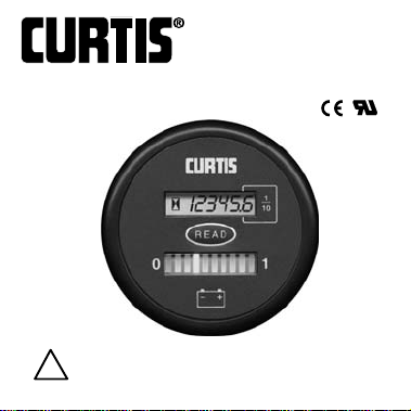
MODEL 833
“FUEL” GAGE/HOUR METER
W/“PUSH-
Read Instructions Carefully !
!
®
Page 2

Safety Instructions
This instrument was manufactured and tested
according to the applicable technical standards.It complies with
all the safety regulations as shipped from the factory.
Installation and startup must be performed by skilled personnel.
Failure to install and operate the unit in accordance with these
instructions may result in damage or injury.
If safe operation of the instrument can no longer be ensured,
stop and secure it against accidental operation.
If instrument failure or malfunction may cause personal injury or
material damage, use additional safety measures such as limit
switches, guards, etc.
Read the Operating Instructions carefully before startup.
Note the safety instructions marked with this
warning symbol in this manual.
!
!
Page 3

TABLE OF CONTENTS Page
1. Model Encodement 2
2.Technical Specifications
2.1 Electrical 4
2.2 Mechanical 5
2.3 Environmental 6
3. Installation 7
4. Operation 14
5.Troubleshooting 16
6. Maintenance 17
!
Page 4

2
1. MODEL ENCODEMENT
833RB vvvv w
Voltage
0024
Reset level
B = 2.09 VPC
Page 5

3
xy zzzz
Discharge profile
C = Adjustable
(See T ab le 3.)
Output
J = N.C. holding relay
Contact rating =
3 Amps
when continuously
closed, 1 Amp
when opening
316O
O = Curtis
logo
!
Page 6

4
2. TECHNICAL SPECIFICATIONS
2.1 Electrical
Operating Range
± 25% of nominal voltage
Operating Current
Voltage (volts) Nominal Current (mA) Maximum Current (mA)
24 18 28
Relay Contact Ratings
Voltage:200 VDC (max)
Current: 1 ADC (max)
(3 ADC max when continuously closed)
Power: 50 W (max)
!
Page 7

2.2 Mechanical
Display
Battery state-of-charge: 10-bar, tri-color LED
Hour Meter: 6-digit LCD, 5mm high
Resolution
Hour Meter
99,999.9 Hours
Hardware Kit
Mounting bracket, thumbnuts or M4 Hex nuts (2),
lock washers (2), mating connector Molex
No.39-01-2085, w/pins No.39-00-0039, no
connectors in bulk shipments.
Panel Cutout
52mm, 21/16” diameter
5
!
Page 8

6
2.3 Environmental
Temperature
Operating: -4 0 °C to +65° C (Standard Mode)
-10° C to +65° C (Push-to-read Mode)
Storage: -50°C to + 90° C
Humidity 95% RH (Non Condensing) at 38°C
Shock &
Vibration 2.2 G, 20-200 Hz; 20 minute period;
X,Y,Z, 13 cycles each
Enclosure IP65 (face)
!
Page 9

7
3. INSTALLATION
The Model 833 Installation Kit includes a
pre-assembled mating connector with
5” terminated wires.
Ask for Curtis Part Number 15369002.
The Model 833 fits into a dash-panel cutout measuring
21/16” (52 mm).
Terminal Assignment (see diagram on page 13)
Pin 8 = Battery +
Pin 8 to battery +
!
Page 10

8
Pin 5 = Battery –
Connect to battery ground as close to battery
as possible.
Pin 2 = Keyswitch
The keyswitch turns on and off the LED display of the
battery discharge indicator.Monitoring of the battery
continues when Pin 2 is turned off and the display
is not lit.
The hour meter display is unaffected by Pin 2, although
it cannot accumulate more time as long as the
keyswitch pin is not energized.The control input HRM
(+) is enabled by the keyswitch.Pin 2 is connected to
the vehicle’s keyswitch.
Pins 1, 2, 6 & 7 = Hour Meter Control (+)
In normal operation, Pin 1, 6 or 7 are connected when
using normal hour meter function. It is possible to
OR the hour meter between the three inputs so that it
accumulates the total time either system is on.Hour
meter control logic is detailed in Table 2.
!
Page 11

9
Pin 3 = Relay (+)
Pin 3 connects in series with the lift coil circuit (or
the circuit to be switched at empty).For holding relay
(J), Pin 3 must be electrically closer to battery +
than Pin 4
Pin 4 = Relay (–)
Pin 4 also connects in series with the circuit to be
switched at empty.
Page 12

Table 1. Hour Meter Control Lines & Impedance
Specifications
Model Low Voltage High Voltage Min. Impedance
Maximum Minimum HRM+ HRM-
24VDC 5.0 VDC 15.0 VDC 90 kΩ 30 kΩ
Table 2. Hour Meter Control Logic
Key HRM HRM HRM Hour Icon
switch (+) (+) (+) meter
Off x x x Display only Steady
On V
H
xx On Flashing
On x V
H
xOnFlashing
On x
x
V
H
On Flashing
On V
L
V
L
V
L
Display Flashing
or open or open or open only
!
10!11
Page 13

NOTE: Fuses and Wires
Regulations may require that the Model 833 be
fused. If installing a fuse, use a 10A fuse wired with
1.5mm or equivalent wire.The voltage drop across the fuse,
its holder, and connectors must be less than 1% of the
nominal system voltage.
Discharge Adjustments
Table 3 lists the voltages per cell under load that correspond
to an empty indication on the gauge (lockout point).
Table 3. Discharge Adjustment Settings
Setting Volt/Cell at Empty
K 1.57
L 1.63
M 1.68
N 1.73 (factory setting)
O 1.78
P 1.82
Q 1.84
R 1.86
S 1.89
T 1.91
U 1.93
Page 14

12
CURTIS Model 833 Rear View
!
Page 15

13
Connections for Typical Model 833 Application
Vehicle system voltage is the higher of the two operating
voltages of a dual voltage unit. Hour meter measures
“keyswitch on”time.
!
Page 16

14
4. OPERATION
Display
The Curtis Model 833 combines in one instrument a
completely solid state LED battery state-of-charge
indicator, an LCD hour meter, and lift lockout.
Only when battery is properly charged is right
most LED (1) lit. As battery’s state-of-charge decreases,
successive LEDs
light up, one at
a time.
2nd from left LED
flashes indicating
“energy reserve”
(70% discharged).
The left most 2 LEDs
flash indicating “empty”
(80% depth of discharge). At this point,
lift lockout occurs.
LCD Hour Meter
Page 17

15
Push-to-read
When the front button is depressed, the LCD will display
the hour meter reading for 6 seconds min.The hour
meter will not accumulate time during this operation.
Reset type/level (after or during recharge)
CTR = Charge Tracking Reset
If the gage is connected to the battery during recharge,
the gage will track the battery charge level.
OCR = Open Circuit Reset
If the gage is disconnected from the battery during
recharge, the gage will retain the last indication.It will
advance to full when reconnected only if the battery voltage
is above the OCR level.For standard (“B”) reset, OCR =
2.09 VPC*.
*VPC = volts per cell.
!
Page 18

16
5.Troubleshooting
The following checklist should help you to
troubleshoot any problems with the instrument.
Problem Possible Causes
No display Terminals not connected or
improper voltage
Stays at FULL Instrument voltage does not
match battery voltage,
B+ connected to the wrong
terminal
Will not reset Instrument voltage does not
match battery voltage, or battery
not fully charged
Resets w/o charging battery Not connected directly to
battery terminals
EMPTY too soon B+ connected to wrong terminal,
or instrument voltage does not
match battery voltage, or
terminals not directly connected
to battery
Page 19

17
6. Maintenance
Model 833 Series is not serviceable in the field. Units returned
to the factory within the warranty period (see inside backcover)
will be replaced without charge.
Page 20

Guarantee - Curtis Instruments’products and/or components
are guaranteed against defects in workmanship and material
for a period of two years, or as defined in the individual
product literature, from date of shipment from our factory,
when applied in a proper application within specified ratings.
This guarantee is limited to repair or replacement F.O.B. our
factory.There is no further warranty or implied representation,
guarantee, promise or agreement as to any Curtis Instruments
product and/or component. Curtis Instruments, Inc., cannot
assume responsibility or accept invoices for unauthorized
repairs to its products and/or components, even though
defective.In no case will Curtis Instruments’ responsibility
extend to products, components or equipment not of its
manufacture.Under no circumstances shall Curtis Instruments,
Inc., be liable for any special or consequential damages or
loss of profits or other damages. Returned goods will not be
accepted unless identified by a Curtis Return Material
Authorization (RMA).
All specifications are subject to change
without notice.
Page 21

CURTIS INSTRUMENTS, INC.
200 Kisco Avenue, Mt. Kisco, NY 10549
Tel. (914) 666-2971 • FAX (914) 666-2188
53024 REV A 7/01
 Loading...