

Page 1
FIND OUT MORE
ON
THE WEB.
WILBURCURTIS.COM
Installation Instructions,
Service & Warranty Information
Revised: May 2002
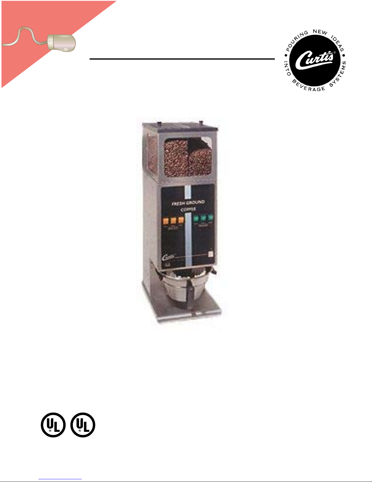
MODELS INCLUDEDMODELS INCLUDED
MODELS INCLUDED
MODELS INCLUDEDMODELS INCLUDED
••
• ILG
••
••
• ILGS
••
INTERLOCK COFFEE GRINDERS
WILBUR CURTIS COMPANY Montebello, CA 90640
C
ISO 9001 REGISTERED
FOR THE LATEST SPEC INFORMATION GO TO WWW.WILBURCURTIS.COM
ILG InterLock Grinder
DRAFT COPY
Not Released. This Version Exists as File No.
I:\DIAGRAMS\FRANK\FX-134.p65
•
Page 2

IND OUT MORE
F
FIND OUT MORE
ON
THE WEB.
ON
THE WEB.
WILBURCURTIS.COM
WILBURCURTIS.COM
WW
W
WW
ILBURILBUR
ILBUR
ILBURILBUR
C C
C
C C
URTISURTIS
URTIS
URTISURTIS
C C
C
C C
OMPOMP
OMP
OMPOMP
ANYANY
ANY
ANYANY
InterLock Coffee Grinders - Instructions
, I, I
, I
, I, I
NCNC
NC
NCNC
..
.
..
Models Included
ILG
ILGS
CAUTION: CAUTION:
CAUTION: Please use
CAUTION: CAUTION:
this setup procedure
this grinder. Failure to follow the
instructions can result in injury or
the voiding of the warranty.
before attempting to use
WARNING TO AVOID
SCALDING, Do not
remove brewcone whil
brew light is flashing.
Important Safeguards/Conventions
This appliance is designed for commercial use. Any servicing other than cleaning and maintenance should be performed by an
authorized Wilbur Curtis service center.
• Do NOT immerse the unit in water or any other liquid
• To reduce the risk of fire or electric shock, do NOT open top panel. No user serviceable parts inside. Repair should be done
only by authorized service personnel.
• Keep hands and other items away from hot parts of unit during operation.
• Never clean with scouring powders or harsh implements.
ConventionsConventions
Conventions
ConventionsConventions
WW
ARNINGS – ARNINGS –
W
ARNINGS –
WW
ARNINGS – ARNINGS –
QUICK STQUICK ST
QUICK ST
QUICK STQUICK ST
SETUPSETUP
SETUP
SETUPSETUP
1. Install the grinder on a firm, level base in a location where it can be connected to a grounded electrical outlet of 120VAC,
rated at 15 amps minimum.
2. Test the unit by running some whole bean coffee through the grinder. If any problems are encountered, refer to the complete
troubleshooting section at www.wilburcurtis.com or call Technical Service at 800-995-0417.
CONNECTING THE INTERLOCK GRINDERCONNECTING THE INTERLOCK GRINDER
CONNECTING THE INTERLOCK GRINDER
CONNECTING THE INTERLOCK GRINDERCONNECTING THE INTERLOCK GRINDER
1. Place grinder near brewer.
2. Remove top cover of brewer.
3. Remove empty strain relief from hole labeled INTERLOCK in back of brewer. Pass end of grinder interlock cable through this
hole. On single head brewers plug the cable directly into timer WC-642. On dual head brewers plug interlock cable into the
timer interlock cable.
4. Place strain relief onto cable outside of brewer. Connection to Gem-312IL timer cable should be inside brewer. Use a plier to
squeeze the strain relief to slip it into the hole. Plug linecord into power outlet.
INTERLOCK OPERAINTERLOCK OPERA
INTERLOCK OPERA
INTERLOCK OPERAINTERLOCK OPERA
1. Open the door on top of the grinder and fill with fresh whole bean coffee. Close the top door.
2. Place an empty Satellite on the warmer deck of the brewer and preheat it by switching on warmer.
ARAR
AR
ARAR
TT
o help ao help a
void personal injurvoid personal injur
T
o help a
void personal injur
TT
o help ao help a
void personal injurvoid personal injur
T & SETUPT & SETUP
T & SETUP
T & SETUPT & SETUP
TING INSTRTING INSTR
TING INSTR
TING INSTRTING INSTR
3. Place a new paper filter into the brewcone.
4. Insert the brewcone into the basket holder arms on the grinder.
5. Press the appropriate grind switch (SMALL, MEDIUM or LARGE).
6. Allow the grind motor to completely stop before removing the brewcone. The
brew selection is now “Locked” in at the brewer and is indicated by the flashing
light on the InterLock brewer.
7.Transfer the filled brewcone to the brewer and press the flashing brew button.
Brew cycle is complete when the brew light stops flashing.
UCTIONSUCTIONS
UCTIONS
UCTIONSUCTIONS
yy
y
yy
Important Notes/Cautions – from the factorImportant Notes/Cautions – from the factor
Important Notes/Cautions – from the factor
Important Notes/Cautions – from the factorImportant Notes/Cautions – from the factor
yy
y
yy
C
ISO 9001 REGISTERED
WILBUR CURTIS COMPANY
Montebello, CA 90640
ADJUSTMENT FOR COARSE THROUGH FINE GRIND*ADJUSTMENT FOR COARSE THROUGH FINE GRIND*
ADJUSTMENT FOR COARSE THROUGH FINE GRIND*
ADJUSTMENT FOR COARSE THROUGH FINE GRIND*ADJUSTMENT FOR COARSE THROUGH FINE GRIND*
1. Empty hopper of coffee beans. Run grinder to clear grinding burrs of coffee.
2. Open housing cover to locate adjustment screw (8) and lock nut (7). Loosen lock nut.
3. Run motor during adjustment. Turning adjustment screw clockwise will result in a finer grind (if, while turning, you hear the
grinding burrs starting to touch, immediately, back off 1/8th turn). Turning counter
clockwise will produce a coarser grind.
4. With a screwdriver holding the adjustment screw in place, tighten the locknut.
5. Run some coffee beans through the machine to check the grind adjustment.
6. Replace front cover on machine.
*This adjustment may change the amount of ground coffee dispensed.
CHANGING A BROKEN SHEAR DISKCHANGING A BROKEN SHEAR DISK
CHANGING A BROKEN SHEAR DISK
CHANGING A BROKEN SHEAR DISKCHANGING A BROKEN SHEAR DISK
1. Unplug the power cord.
2. Empty the hopper of beans.
3. Take out the thumb screws (10) to remove the grind cap (6).
4. Pull out the grinding burr/feed worm assembly (2). The inner half of the grinding burr set
will remain in the housing.
5. Separate the shear cap (5) and shear drive (3). The snapped shear disk (4) should fall
out of it’s slot on the shear drive.
6. Inspect and clean housing (1) of any coffee or debris. Especially look for anything that may have broken the shear disk.
7. Re-insert the feed worm and grinding burr on to the motor shaft.
8. Push shear drive through burr/feed worm assembly and align large slot with tongue on the motor shaft.
9. Rotate burr/feed worm assembly to align slot with narrow slot on shear drive.
10. Insert a new shear disk into slot. Cover with the shear cap.
11. Replace grind cap and thumb screws.
FOR THE LATEST SPECIFICATIONS AND INFORMATION GO TO
WWW.WILBURCURTIS.COM
10
1
2
4
8
7
5
6
3
1
Page 3

PROGRAMMING THE
GRINDER
NOTE: Time settings in
this table are only
approximate. Amounts
will vary with grind texture and
specific coffee bean. Weigh your
output, then make adjustments as
necessary
PROGRAMMING THE ILG GRINDER
1. Turn ON/OFF switch to the OFF position.
2. Open the lower front panel by removing the holding screws.
WARNING: The next step will activate the 110 VAC circuit and some wires will be energized. Proceed with
CAUTION and avoid contact with "live" wires.
3. Turn ON/OFF switch to the ON position. This turns on the components in the grinder and
timer board.
4. Locate the timer and move the RUN-PROGRAM switch to the PROGRAM position (see
illustration, right).
5. Locate the grinding switch indicating the amount of coffee to be ground (12, 24, or 36
cup - decaf or regular) on the front panel.
6. Press and hold the desired grinding switch for a precise amount of seconds to be equal
to the required grinding time. At the time the grinding switch is depressed, the following
will happen:
! The original stored time will reset to zero and the timer will start a new count.
! The auger and grinder motor will activate.
At the time of release of the grinding switch, the following will happen:
! The timer is ready for adding or storing a preset time.
! The auger will stop but the grinder motor will continue until the housing is cleared of ground coffee.
7. You can still add time to the same grinding switch. This "adding" function is active only for the grinding switch you are
programming at this time and until the RUN/PROGRAM switch is moved to the RUN position or until you program a
Seconds OuncesSeconds Ounces
4
5
6
7
8
10
12
1.3
1.5
1.8
2.0
2.5
3.0
3.7
15
20
25
30
35
40
45
10.6
11.8
13.5
different grinding switch. To add time, press and hold the same grinding
switch for the seconds you wish to add to this grinding switch.
8. Wait until the grinder motor stops, then switch the
4.5
switch switch
switch to the RUN position. This will store the previously set times.
switch switch
6.2
7.6
9.1
ON/OFF switchON/OFF switch
9. Turn
ON/OFF switch to the OFF position.
ON/OFF switchON/OFF switch
10. Replace (remount) the Lower Front Panel.
RUN/PROGRAMRUN/PROGRAM
RUN/PROGRAM
RUN/PROGRAMRUN/PROGRAM
ILLUSTRATED PARTS
LIST
Grinder MotorGrinder Motor
Grinder Motor
Grinder MotorGrinder Motor
B
7
8
15
13
14
DESCRIPTION
MOTOR CRUSHING GRINDER ASSY 120VAC
MOTOR, GRINDER 120VAC
CAPACITOR, COFFEE GRINDER ASSY
SHEAR DRIVE COFFEE GRINDER
SHEAR DISK
CAP , SHEAR DISK GRINDERS
COVER, GRINDER HOUSING W/LABEL
SCREW & THRUST PIN ADJUSTING ASSY
SPRINGBAFFLE LONG, NITRIC ACID COLORING
SPRING BAFFLE SHORT, NITRIC ACID COLORING
BAFFLE, SPOUT
SPOUT, GRINDER HOUSING
BURRS, SET CRUSH HIGH FLOW
SPRING, TENSION COFFEE GRINDER
WORM FEEDING ASSY CCG
2
ITEM PART N°
1
WC-9135
2
WC-91022
3
WC-91026
4
WC-91024
5
WC-91025
6
WC-91016
7
WC-91017
8
WC-91015
9
WC-91029
10
WC-91027
11
WC-91028
12
WC-91023
13
WC-91045
14
WC-91021
15
WC-91020
6
B
PARTS DIAGRAM
Hopper & Top CoverHopper & Top Cover
Hopper & Top Cover
Hopper & Top CoverHopper & Top Cover
ILGS OnlyILGS Only
ILGS Only
ILGS OnlyILGS Only
1
3
5
4
A
2
1
2
16
9
12
10
3
11
Page 4

PARTS DIAGRAMS
Center Cover & GearCenter Cover & Gear
Center Cover & Gear
Center Cover & GearCenter Cover & Gear
Motor ILG & ILGSMotor ILG & ILGS
Motor ILG & ILGS
Motor ILG & ILGSMotor ILG & ILGS
Hopper & Top CoverHopper & Top Cover
Hopper & Top Cover
Hopper & Top CoverHopper & Top Cover
ILG OnlyILG Only
ILG Only
ILG OnlyILG Only
15
16
4
5
17
22
6
14
7
8
9
10
11
21
23
24
25
18
20
19
13
12
Item Part No. Description
1
2
3
4
5
6
7
8
9
9A
10
11
12
13
14
15
16
17
18
19
20
21
21A
22
23
24
25
26
27
28
29
30
31
32
33
33A
WC-9129
WC-9117
WC-9187
WC-9118
WC-9131
WC-9143
WC-9160
WC-9144
WC-9132
WC-9188
WC-9142
WC-9116
WC-9158
WC-9183
WC-91013
WC-9130
WC-9134
WC-9151
WC-1504
WC-9164
WC-9145
WC-6326
WC-6334
WC- 124
WC- 122
WC- 121
WC-38001
WC-75135
WC-3502
WC-4813
WC-9141
WC-9135
WC-9155
WC-9123
WC- 644
WC- 652
COVER ASSEMBLY TOP ILGS
HOPPER, COFFEE BEAN S.H. GRINDER
WINDOW, ACRYLIC ILGS
COVER, HOPPER DUAL GRINDER ASSY
WINDOW, ACRYLIC DUAL GRINDER
SPACER, 5/8" AGITATION WHEEL (OPTIONAL)
WHEEL, GRINDER AGITATION CCG (OPTIONAL)
SPACER, 9/32" AGITATION WHEEL (OPTIONAL)
DIVIDER, DUAL HOPPER, SS
DIVIDER, W/HOLE ILG-11/DHG-11 (AS SHOWN, OPTIONAL)
SHAFT AGITATION WHEEL (OPTIONAL)
DUAL HOPPER GRINDER ASSY
AUGER ASSY DHG/ILG/ILGD
BEARING, AUGER BR
WRAP, DUAL HOPPER ILGD
FUNNEL, DHG/ILGD
SHEILD, HOUSING, ILGD/ILG/SHG/DHG
MOTOR, GEAR 115V DUAL GRINDER
BREAKER, CIRCUIT 10A 120/250VAC
COVER ASSEMBLY , SPOUT
COVER, TIMER BOTTOM
LABEL, SWITCH PANEL, ILG
LABEL, SWITCH PANEL, ILGS
SWITCH, DECAF 115V
SWITCH, REGULAR 115V
SWITCH, ON/OFF 115V
LABEL, IL TIMER PROGRAM
BASE, GRINDER
LEG, SCREW BUMPER 8/32 STUD
SCREW, SHOULDER, 5/16 x 5/8
BASKET HOLDER ASSY
MOTOR, CRUSHING GRINDER ASSY 120VAC SHG/DHG/ILGD
SPRING, BASKET HOLDER
NUT, HEX ADAPTER GRINDER
TIMER
TIMER GRINDER 120V 50 SEC ILGS
Motor & Base ILG & ILGSMotor & Base ILG & ILGS
Motor & Base ILG & ILGS
Motor & Base ILG & ILGSMotor & Base ILG & ILGS
30
32
31
29
28
33
26
27
3
Page 5

ELECTRICAL SCHEMAELECTRICAL SCHEMA
ELECTRICAL SCHEMA
ELECTRICAL SCHEMAELECTRICAL SCHEMA
TICTIC
TIC
TICTIC
WARRANTY We hereby certify that the products manufactured by the Wilbur Curtis Company, Inc., are, to thebest of our knowledge, free from all defects and faulty workmanship.
The following warranties and conditions are applicable:
• 90 Days for Labor and 1 Year Parts from Date of Purchase from Factory: This warranty covers all electrical parts, fittings and tubing.
• 40 Months or 40, 000 Pounds of Coffee on a set of Grinding Burrs. (ADS Grinders)
• 2 Years from Date of Purchase: This warranty covers electronic control boards and leaking or pitting of a stainless steel body of a Brewer or Urn.
• 90 Days from Date of Purchase: On replacement parts that have been installed on out of warranty equipment
All in-warranty service calls must have prior authorization from the manufacturer. For an RMA (Return Merchandise Authorization) number, call the Technical Service Department at 1-800-995-0417. The Wilbur Curtis
Company will allow up to 100 miles, round trip, per in-warranty service call.
CONDITIONS & EXCEPTIONS
The warranty covers original equipment at time of purchase only. The Wilbur Curtis Company, Inc., assumes no responsibility for substitute replacement parts installed on Curtis equipment that have not been purchased
from the Wilbur Curtis Company. Inc The Wilbur Curtis Company will not accept any responsibility if the following conditions are not met. The warranty does not cover and is void under these circumstances:
1) Improper operation of equipment. The equipment must be used for its designed and intended purpose and function.
2) Improper installation of equipment. This equipment must be installed by a professional, certified technician and must comply with all local electrical, mechanical and plumbing codes.
3) Wilbur Curtis Company will not be responsible for the operation of equipment at other than the stated voltages on the serial plate.
4) Abuse or neglect (including failure to periodically clean or remove lime accumulations). Manufacturer is not responsible for variation in equipment operation due to excessive lime or local water
conditions.
5) Replacement of items subject to normal use and wear. This shall include, but is not limited to, light bulbs, shear disks, “0” rings, gaskets, canister assemblies. whipper chambers and plates, mixing
bowls, agitation assemblies and whipper propellers.
6) Any faults resulting from inadequate water supply. This includes, but is not limited to, excessive or low water pressure, and inadequate or fluctuating water flow rate.
7) All repairs and/or replacements are subject to our decision that the workmanship or parts were faulty and the defects showed up under normal use.
8) All labor shall be performed during regular working hours. Overtime charges are the responsibility of the owner.
9) Charges incurred by delays, waiting time, or operating restrictions that hinder the service technician’s ability to perform service is the responsibility of the owner of the equipment.
This includes institutional and correctional facilities.
10) All claims under this warranty must be submitted to the Wilbur Curtis Company Technical Service Department before return of the unit to the factory.
11) All equipment returned to us must be repackaged properly in the original carton. No units will be accepted if they are damaged in transit due to improper packaging.
12) Damaged in transit.
13) The resetting of safety thermostats and circuit breakers, programming and temperature adjustments are the responsibility of the equipment owner.
NO UNITS OR PARTS WILL BE ACCEPTED WITHOUT A RETURN MERCHANDISE AUTHORIZATION (RMA). RMA NUMBER MUST BE MARKED ON THE CARTON OR SHIPPING LABEL.
All in-warranty service calls must be performed by an authorized service center, where service is available. Call the factory for location near you.
WILBUR CURTIS CO., INC.
6913 Acco St., Montebello, CA 90640-5403 USA
Phone: 800/421-6150 Fax: 323-837-2410
Technical Service Phone: 800/995-0417 (M-F 5:30A - 4:00P PST) E-Mail: techservice@wilburcurtis.com
Web Site: www.wilburcurtis.com
FOR THE LATEST SPECIFICATION INFORMATION GO TO WWW.WILBURCURTIS.COM
4
Printed in U.S.A. 10/01 F-1995-S Rev NC
10/18/01.10.8 . edr 3173 Rev NC
Made TimerTable Chg 1/7/02
 Loading...