

Page 1

MMAANNUUAALL
DIGITAL INSTRUMENTATION
Page 2
1.0 Technical Specifications
1.1 Electrical
Power Requirements
Auto-ranging - 12V to 80V DC ± 25% (9V to 100V DC).
Operating Current
Total system current entering the V+ pin is a function of system voltage, LED alert/warning icons, backlight, LCD heater and sender loads.
The table below illustrates the typical and maximum operating current
for a panel with a V+ voltage of 12V with the sender inputs left as
open circuit. The LCD heater circuit typically consumes 310mA when
active. The backlight circuit typically consumes 30mA. For higher
V+ voltages the operating current is reduced accordingly.
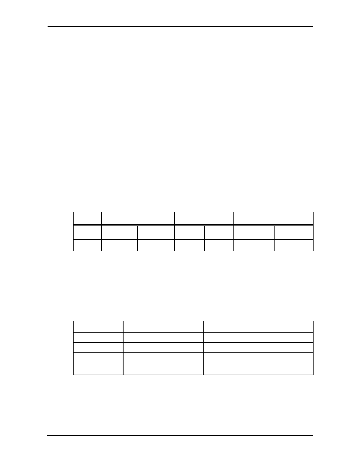
enGage™IV Operating Current (mA)
Without Backlight With Backlight With LCD Heater on
V+ Typ. Max Typ. Max Typ. Max
12.0 30 40 60 70 370 380
Operating currents for V+ of 24, 36, 48, 60, 72 and 80 VDC are lower than this listing.
1.2 Mechanical
Size and Weight
Item Enclosed Unit (T) PCB & LCD Module Only (P)
Bezel H x W 120 x 180 mm N / A
Case H x W 91.8 mm x 137.8 mm 82.6 mm x 128.5 mm
Depth 53.5 mm 38.8 mm
Weight 400 g max 200 g max
Display
Dot Matrix LCD (128 X 240 pixels), Backlit
Curtis enGage™ IV Manual
page 1
Page 3

Hour Meter Range & Resolution
Hour Meter: 99,999.9 Total Hours, 0.1 hours resolution.
Maintenance Monitor: 999 Total Hours (countdown), 1 hour resolution
Panel Cutout
92 (+ 0.8/-0.0) mm x 138 (+1.0/-0.0) mm
1.3 Environmental
Operating Temperature Range: -40°C to +70°C
Storage Temperature Range: -50°C to +90°C as per SAE J1455,
section 4.1.1.5.
Thermal Cycling As per SAE J1455 section 4.1.3.1.
(Applicable To Enclosed Units Only): to +80°C
Thermal Shock As per SAE J1455 section 4.1.3.2.
(Applicable To Enclosed Units Only): to +80°C
Humidity 95% RH (non-condensing) at +38°C
(Applicable To Enclosed Units Only): as per SAE J1455, section 4.2.3.
Shock SAE J 1378 March 83. Amplitude
(Applicable To Enclosed Units Only): 44 - 55g, half sine, 9-13 ms duration.
Vibration SAE J 1378 March 83. Double
(Applicable To Enclosed Units Only): amplitude of 1.53 mm with
frequency sweep from 10-80-10 Hz
(20 g max.) at intervals of 1 minute.
IP Ratings Face sealed to IP65.
(Applicable To Enclosed Units Only): Rear seal Sealed to IP40.
Curtis enGage™ IV Manual
page 2
Page 4

2.0 Installation
2.1 Terminal Assignments – Main connector (J1)
Curtis enGage™ IV Manual
page 3
Pin# Function
1 Battery V +
2 Common
3 Sender1 input (R, V, I)
4 Sender2 input (R, V, I)
5 Sender3 input (R, V, I, Frequency*)
6 Sender4 input (R, V, I, Frequency**)
7 Switched Input 1
8 Switched Input 2
9 Switched Input 3
10 Switched Input 4
11 Switched Input 5
12 Switched Input 6
13 Keyswitch Input
14 MOSFET output 1
15 MOSFET output 2
16 MOSFET output 3
17 Range Select V + (BDI
see table in Section 3.0)
18 n/c
19 LCD Heater V +
20 Dimming Control
*Speedometer, Odometer
**Tachometer
Note: Sender 1, 2, 3 and 4 inputs are limited to 60V max. Voltages beyond
that, will damage the instrument.
Page 5

2.1 Terminal Assignments – Communications Connector (J2)
Curtis enGage™ IV Manual
page 4
Pin# Function
1 CAN H
2 CAN L
3 GND
4n/c
5 CAN Terminator 1
6 CAN Terminator 2
7n/c
8n/c
9 SCI Rx
10 GND
11 SCI Tx
12 +7V Out (<10mA – unregulated)
2.2 Mounting
Enclosed unit snaps into panel cutout using molded-in fingers. An
optional mounting bracket (Curtis P/N 17644307) can be used for
additionsal support. Module units are attached via screw holes in the
four corners of the PCB.
2.3 Main Connector
20-pin AMP Mini Universal Mate-N-Lok. (Mating connector: AMP
part number 770585-1).
2.4 Communications Connector
12-pin AMP Mini Universal Mate-N-Lok. (Mating connector: AMP
part number 770581-1).
Page 6

2.5 User Interface
Curtis enGage™ IV series instruments include 3 front panel buttons
for navigating through a menu system and programming the following
specific functions:
• Time Of Day Clock
• Battery Discharge Indicator
• Maintenance Intervals
• Settable Hour Meters
• Units - Metric / English Conversion
2.6 Configuring Your Panel
In order to configure an enGage™ IV panel, main power must be
applied (12 – 80VDC) to V+ and V- and the keyswitch must be active.
Following a power up sequence, the OEM logo (if applicable) will be
displayed. Once the start-up process is complete, the specified default
(normal) monitoring screen will appear.
2.6.1 enGage™ IV Menu System
The menu system is activated by pressing and holding the select
button for 3 seconds and then releasing when main menu appears.
2.6.2 Choosing Items Within Menu System
Items are selected within each menu utilizing the up / down
arrows on right side of panel. Once the desired item is chosen /
outlined, press the select button once and release. You will then see a
new set of choices for the previously selected item.
Curtis enGage™ IV Manual
page 5
Page 7

Curtis enGage™ IV Manual
page 6
mode = NORM mode = MENU
Main Menu 1
10 CHANGE SETTINGS
20 MAINT. MONITORS
30 METRIC/ENGLISH
40 SET CLOCK
50 EXIT MENU
Sub-menu 10
11 ADVANCED SETTINGS
12 CHANGE PASSWORD
1x EXIT
Sub-menu 40
41 SELECT 12/24 12H
42 SET CLOCK HH:MM
4x EXIT
No Sub-menus
Sub-menu 30
31 METRIC/ENGLISH X
3x EXIT
No Sub-menus
Password Level 2
Sub-menu 11
11.1 SET MM INTERVALS
11.2 SET HOURMETERS
11.3 SET BDI PROFILE
11.4 RUN DIAGNOSTICS
11.x EXIT
Sub-menu 20
21 RESET ALL
22 RESET MAINT. MON. 1
23 RESET MAINT. MON. 2
24 RESET MAINT. MON. 3
2x EXIT
Sub-menu 12
12.1 ENTER NEW USER P/W:
12.2 ENTER NEW OEM P/W:
12.x EXIT
Password Level 1
NOTES: 1. ALL MENUS EXIT TO THEIR PARENT MENU
2. SOME ENTRIES NOT AVAILABLE IF FUNCTION
IS NOT AVAILABLE
3. KEYSWITCH OFF/ON EXITS THE MENU
FUNCTIONALITY:
Press ENTER for 3 Sec
to enter MENU mode
Press UP/DN to navigate
ENTER to select
UP/DN to change
ENTER to accept
Sub-menu 111
11.11 SET MM 1 INTERVAL
11.12 SET MM 2 INTERVAL
11.13 SET MM 3 INTERVAL
11.1x EXIT
Sub-menu 112
11.21 RESET ALL
11.22 SET HRM 1
11.23 SET HRM 2
11.24 SET HRM 3
11.2x EXIT
Sub-menu 113
11.31 SET BDI CTR FULL
11.32 SET BDI CTR EMPTY
11.33 SET BDI OCR
11.34 SET BDI ...
11.3x EXIT
Sub-menu 114
11.41 ANALOG INPUTS
11.42 DIGITAL INPUTS
11.43 MOSFETS
11.44 LCD HEATER
11.4x EXIT
Sub-menu 1121
11.211 HRM 1 HHHHH.h
11.212 HRM 2 HHHHH.h
11.213 HRM 3 HHHHH.h
11.214 RESET
11.21x EXIT
Sub-menu 1122
11.221 HRM 1 HHHHH.h
11.22x EXIT
Sub-menu 1123
11.231 HRM 2 HHHHH.h
11.23x EXIT
Sub-menu 1124
11.241 HRM 3 HHHHH.h
11.24x EXIT
Sub-menu 21
21.1 MM 1 HHH
21.2 MM 2 HHH
21.3 MM 3 HHH
21.4 RESET
21.x EXIT
Sub-menu 22
22.1 MM 1 HHH
22.x EXIT
Sub-menu 23
23.1 MM 2 HHH
23.x EXIT
Sub-menu 24
24.1 MM 3 HHH
24.x EXIT
2.6.3 enGage™ IV Menu System Navigation
The diagram below illustrates the navigation through the menu system.
enGage IV Menu System
Page 8

2.6.4 Changing Parameters Within Menu System
2.6.4.1 Maintenance Monitor
Starting from the main menu, choose "Maint Monitors" then "Reset
All".
Return to the main menu by utilizing the up / down arrows on panel
and select "Exit".
2.6.4.2 Metric / English
Starting from the main menu, choose "Metric / English" then
"Metric / English" again. Once the left button is pressed to select
this choice, a box will appear around the E / M portion of the item.
Utilizing the up / down arrows on the right side of panel, enter E or M.
Once the desired choice is made, press the select button on the left side
of the panel to accept the selection.
Return to the main menu by utilizing the up / down arrows on panel
and select "Exit".
2.6.4.3 Set Clock
Starting from the main menu, choose "Set Clock" then "Set Clock"
again. Once the left button is pressed to select this choice, a set of "up
arrows" will appear under the hour digits on left portion of the item.
Utilizing the up / down arrows on the right side of panel, enter the
desired time in hours. Then press left button on front panel to accept
the data. The "up arrows" will then move to the minutes portion of the
time. Utilizing the up / down arrows on the right side of panel, enter
the desired time in minutes. Once the desired choice is made, press
the select button on the left side of the panel to accept the data.
Return to the main menu by utilizing the up / down arrows on panel
and selecting "Exit".
Curtis enGage™ IV Manual
page 7
Page 9

Curtis enGage™ IV Manual
page 8
2.6.4.4 Advanced Settings / Set Hour Meter
Starting from the main menu, choose "Advanced Settings" then,
choose "Set Hour Meters". From the next menu listing choose
"Reset All".
Return to the main menu by utilizing the up / down arrows on panel
and select "Exit".
2.6.4.5 Exiting Menu Mode
This can be accomplished by selecting the "Exit" menu choice.
3.0 Operation
Buttons are utilized for menu navigation as described earlier.
3.1 A uto-range (BDI)
Curtis enGage™ IV has an operating voltage range for V+ from 12 to
80 VDC +/- 25%. The source to which pin J1-17 is connected will
configure the instrument for the correct Battery Discharge Indicator
system voltage. Refer to table below for J1-17 connection depending
on voltage range desired.
Pin J1-17 Connection Guide
When configured to display other instruments (not BDI), terminal J117 is unused. Note that for all analog sender inputs (J1-3, J1-4, J1-5,
J1-6), the sender range is factory configured.
System Voltage J1-17Connection
12 No Connection
24 V+
36 V48 No Connection
60 V+
72 V80 No Connection
Page 10

4.0 Trouble-shooting
General
Problem Possible Cause
No Display V+ (keyswitch) voltage not present at J1-13.
Battery voltage too low. Battery terminals
not connected.
BDI Function
Problem Possible Cause
No Display Terminals Not Connected.
Improper Voltage – Check Pin J1-17
Stays At FULL Instrument voltage range selected does not
match battery voltage.
Range Select V+ connected to wrong
terminal.
Will Not Reset Instrument voltage does not match battery
voltage.
Battery not fully charged.
Battery may be defective.
Resets Without Not connected directly to battery terminals.
Charging Battery
Empty Too Soon Range Select V+ connected to wrong
terminal.
Instrument voltage does not match battery
voltage.
Terminals not connected directly to battery.
Curtis enGage™ IV Manual
page 9
Page 11

Curtis enGage™ IV Manual
page 10
Sender Function
Problem Possible Cause
No Display Terminals not connected.
Improper voltage.
Stays At Sender or Sender Connection Problems.
Maximum/Minimum Sender connected to wrong terminal.
Incorrect sender used.
Maintenance Function
Problem Possible Cause
Will Not Reset Procedure as described in Section 2.6 not being
followed.
5.0 Maintenance
The enGage™ IV 3210 series is not serviceable.
Page 12

Specifications subject to change without notice
© 2004 CURTIS INSTRUMENTS, INC. 53040 REV A 2/04
CURTIS INSTRUMENTS, INC.
200 Kisco Avenue
Mt. Kisco, New York 10549 USA
Tel. 914.666.2971
Fax 914.666.2188
www.curtisinstruments.com
 Loading...