

Page 1
CURTIS DECANTER BREWER
TROUBLESHOOTING GUIDE
Service & Sales
1-800-421-6150
www.wilburcurtis.com
Page 2

Page 3
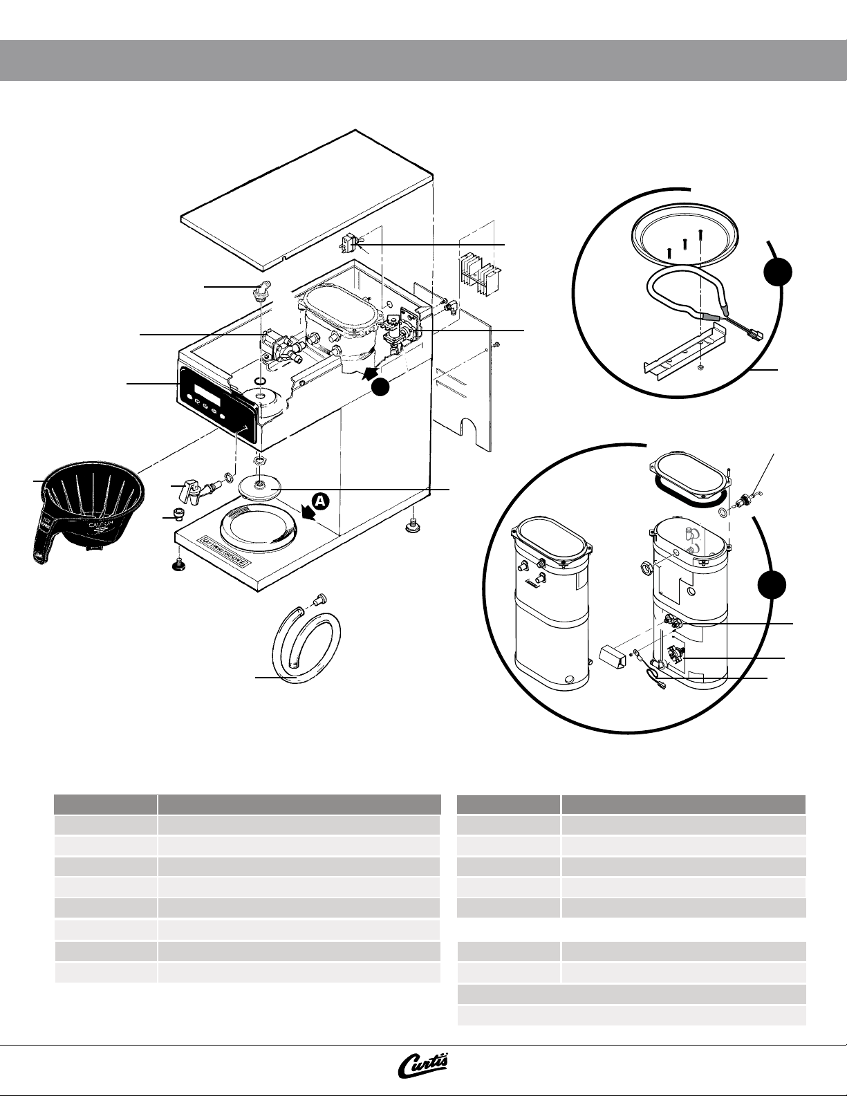
BREWER PARTS IDENTIFICATION
15
9
3
1
12
14
B
2
7
5
4
6
B
10
11
A
8
9
WATER RELATED HEAT RELATED
PART #
1. WC- 826L VALVE, INLET 1.0 GPM 120V
2. WC-5527K KIT, PROBE WATER LVL FITTING, ORING, NUT
3. WC- 889 VALVE, DUMP LEFT 120V 12W
4. WC-29025 SPRAYHEAD, PURPLE ADVANCE FLOW
5. WC-37252 KIT, HOT WATER FAUCET REPLACEMENT
6. WC-1806 SEAT CUP, SILICONE
7. WC-3621-101
8. WC-5310 TUBING, SILICONE
Service & Sales
Service & Sales
1-800-421-6150
1-800-421-6150
DESCRIPTION
BREW CONE, COFEE
PART #
9. WC-1438-101 SENSOR, TEMPERATURE TANK
10. WC- 917-04 HEATING ELEMENT
11. WC- 523 THERMOSTAT, HI LIMIT HEATER
12. WC- 972-102 BREW WARMER
13. WC-6193-0 TRIAC, 40A 600V (NOT ILLUSTRATED)
MASTER CONTROL
14A. WC-37061
14B. WC-37062
14C. WC-37063
15. WC- 102 SWITCH, TOGGLE DPST 25A 125/25OVAC
DESCRIPTION
KIT, LABEL & UCM ALPHA 1GT
KIT, LABEL & UCM ALPHA 2GT
KIT, LABEL & UCM ALPHA 3GT
www.wilburcurtis.com
www.wilburcurtis.com
Page 4

PARTS IMAGES
1
WC-826L
VALVE, INLET 1.0 GPM 120V
2 3
WC-5527K
KIT, PROBE WATER LVL
FITTING, ORING, NUT
5 6 7
WC-37252
KIT, HOT WATER FAUCET
REPLACEMENT
WC-1806
SEAT CUP, SILICONE
VALVE, DUMP LEFT 120V 12W
WC-889
WC-3621-101
BREW CONE, COFEE
4
WC-29025
SPRAYHEAD, PURPLE
ADVANCE FLOW
8
WC-5310
TUBING, SILICONE
9
WC-1438-101
SENSOR, TEMPERATURE TANK
13
WC-6193-0
TRIAC, 40A 600V
10
WC-917-04
HEATING ELEMENT
14
WC-37061, WC-37062
WC-37063
KIT, LABEL & UCM
11
WC-523
THERMOSTAT, HI LIMIT HEATER
15
WC-103
SWITCH, TOGGLE DPST
25A 125/25OVAC
12
WC- 972-102
BREW WARMER
Service & Sales
1-800-421-6150
www.wilburcurtis.com
Page 5

TROUBLESHOOTING INSTRUCTIONS
POWER ISSUES
The unit will not turn on:
Check if the panel breaker is turned on. If it
1
is, proceed to STEP 2.
Check the voltage at the receptacle it should
2
read: L1-N = 120v, N-G = 0v. Proceed to
STEP 3 if accurate.
Check if the power cord is properly con-
3
nected to the receptacle. If it is, proceed to
STEP 4.
Check the toggle switch if it is in the ON
4
position. If it is ON, proceed to STEP 5.
Not heating:
LCD reads “Heating”
Yes:
Verify 120 volts between #2 & #4 on both
sides of the Manual Reset Thermostat.
If no, reset or replace the Manual Reset
Thermostat.
Verify 120 volts across the Toggle Switch.
Yes:
If no, replace the toggle switch.
Check the voltage at the power block, it
5
should read: L1-N = 120v, N-G = 0v.
Check the voltage at the reset thermostat, it
6
should read 120v.
Check the voltage at the toggle switch, it
7
should read 120v.
Verify 120v between pins #8 and #16 on
8
molex connector at UCM.
If all steps were taken and the unit still does
9
not turn on, replace the UCM.
HEATING ISSUES
Overheating/Steaming:
LCD reads “Heating”
Verify that the resistance on the Temperature
Sensor is less than 10k ohms with a hot tank
(200+ degrees) If no, verify correct mounting
and that the walls of the tank are free of mineral deposits. If yes, bypass the sensor using a
jumper with a 5k ohm resistor. If the LCD reads
“ready” and the unit stops heating, replace the
temperature sensor, if not, replace the UCM.
Verify 120 volts across the Heating Ele-
Yes:
ment. If yes, replace the Heating Element.
If no, verify 120 volts between the Triac
gate, Neutral, and L1. If yes, replace the
Triac, if no, replace the UCM.
Verify that the panel breaker is turned on
No:
and the receptacle has 120 volts. If not,
consult an electrician.
WARMER ISSUES
No power to any warmer:
Verify correct programming: (Model number).
Not heating:
Verify 120v at heating element.
Yes: Replace heating element.
No: Verify that the connections and wirings
are good. If OK, replace UCM.
Service & Sales
1-800-421-6150
LCD reads “Ready to Brew”
Check the triac for continuity across A1 & A2,
if continuity is present, replace the triac, if no
continuity, replace UCM.
Ensure that the temperature is adjusted to compensate
i
for high elevation. The factory setting is 200 degrees.
The temperature setting will need to be reduced Two
degrees for every One Thousand feet of elevation.
Constantly hot, even when turned off:
Ensure proper resistence value on the heating
element between 140-170 ohm.
Ensure wiring is not shorted to ground.
Replace UCM.
www.wilburcurtis.com
Page 6

TROUBLESHOOTING INSTRUCTIONS
TANK FILLING ISSUES
Not lling:
Yes:
Does the LCD read “Water Level
Error”?
Yes:
Verify the ow rate to be a minimum of 1
gpm from outlet of the water lter. If not,
ensure that the inlet side of the water
lter is receiving a minimum of 1 gpm. If
yes, replace the water lter. If not, con-
sult a plumber.
No:
Remove the orange wire from the probe.
Does the tank start lling?
Yes:
Replace water level probe
No:
Replace the UCM
BREWING ISSUES
LCD does not read “Brewing”:
If the LCD reads “Ready to Brew” and no
response when Brew Button is pressed, replace
the UCM.
LCD reads “Brewing”:
No water ow from the sprayhead:
Does water ow from the hot water faucet? If
yes, verify 120 volts at the dump valve coil. If
voltage is present at the dump valve coil, replace
the dump valve. If 120 volts is not present at
the dump valve coil, conrm continuety of wiring
between molex connector and Dump Valve. If
okay, replace the UCM. (Verify the resistance on
the dump valve coil to be open in one direction,
and under 2k ohm in the other direction BEFORE
REPLACING THE UCM) If water does not ow
from the hot water faucet, replace the Water Level Probe.
Brewing Short Pots:
Verify that the Hot Water Tank is lling correctly.
(See Tank Filling issues)
Overlling:
Turn OFF toggle switch.
Does the tank continue to ll?
Yes: Replace water inlet valve
No: Ground the probe wire to chassis.
Does the tank continue to still ll?
Yes: Replace the UCM
No: Replace Water Level Probe
Before replacing any parts, verify the
i
following:
Verify that the Dump Valve outlet tting on the tank,
the tubing between the tank outlet and the Sprayhead
tting, the Sprayhead, and Dump Valve are clear of
obstructions.
Ensure correct alignment of the sprayhead tting and
that the tubing is routed properly to allow for maximum
water ow. (No Kinks)
Overowing the Pot:
• Ensure that the Sprayhead has not been removed. Replace as needed.
• Ensure that the Hot Water Tank is not over-
owing (See Tank Filling Issues)
• Ensure that hot water is not owing from the
Dump Valve when the toggle switch is turned
off. If it is, replace the dump valve.
• Ensure Cold Brew Lock is set to 5 degrees
Service & Sales
1-800-421-6150
www.wilburcurtis.com
www.wilburcurtis.com
Page 7

NOTES
__________________________________________________________________________________________
__________________________________________________________________________________________
__________________________________________________________________________________________
__________________________________________________________________________________________
__________________________________________________________________________________________
__________________________________________________________________________________________
__________________________________________________________________________________________
__________________________________________________________________________________________
__________________________________________________________________________________________
__________________________________________________________________________________________
__________________________________________________________________________________________
__________________________________________________________________________________________
__________________________________________________________________________________________
__________________________________________________________________________________________
__________________________________________________________________________________________
__________________________________________________________________________________________
__________________________________________________________________________________________
__________________________________________________________________________________________
__________________________________________________________________________________________
__________________________________________________________________________________________
__________________________________________________________________________________________
__________________________________________________________________________________________
__________________________________________________________________________________________
__________________________________________________________________________________________
__________________________________________________________________________________________
__________________________________________________________________________________________
__________________________________________________________________________________________
__________________________________________________________________________________________
__________________________________________________________________________________________
__________________________________________________________________________________________
__________________________________________________________________________________________
__________________________________________________________________________________________
__________________________________________________________________________________________
Service & Sales
1-800-421-6150
www.wilburcurtis.com
Page 8

Wilbur Curs Co., Inc.
6913 Acco Street, Montebello CA 90640
Customer Service: 800.421.6150 | 323.837.2300
csrassistance@wilburcurs.com
Tech Support: 800.995.0417
www.wilburcurs.com
APR/2015 M111_TS_WC_Alpha_revNC
 Loading...