

Page 1
Model CFB2 shown
Models covered
• CFB1
• CFB2
• CFB3
Wilbur Curtis Co., inC.
Service Manual – Frozen Beverage Dispenser
Important Safeguards/Symbols
Symbols:
WARNING/CAUTION – To advise about conditions that may result in property damage,
personal injury or death
IMPORTANT - Notes about proper operation
WARNING:
• This equipment is designed for commercial use only.
• To reduce the risk of re or electric shock, DO NOT open service panels. There are no user
serviceable parts inside. Any servicing other than cleaning and routine maintenance should
be performed by an authorized Wilbur Curtis Co., Inc. service technician. Refrigeration
equipment must be serviced by a licensed, certied, refrigerant technician.
• Do not install a damaged unit or a unit with a damaged power cord.
• Clean this appliance according to the CLEANING section of this manual before using it for
the rst time. Clean this appliance daily according to the CLEANING section.
• Keep hands and other items away from moving parts during operation.
• Dispose of refrigeration equipment and refrigerants in accordance with current local
environmental protection regulations and laws. This applies to an appliance that is being
replaced and to this unit, when it has reached the end of its service life. DO NOT dispose of
refrigeration equipment in a landll or urban waste. Contact your local governing authorities
for information on disposal requirements.
WARNING:
Read and follow the
setup instructions
before attempting to use this
appliance. Failure to follow these
instructions can result in injury
and/or void the warranty.
EXCESSIVE WEIGHT
WARNING: Due
to weight, this unit
requires a minimum of two
people to lift or reposition.
IMPORTANT: Installer:
Observe all codes and
ordinances.
WILBUR CURTIS CO., INC.
Montebello, CA 90640
For the latest information go to
www.wilburcurtis.com
Phone: 800-421-6150
SETUP INSTRUCTIONS
System Requirements
• Electrical: See the WIRING DIAGRAMS in this
manual or visit www.wilburcurtis.com for your
model. The electrical outlet must be in a location
that allows the unit to be easily disconnected for
service or cleaning.
• Operating Temperature: 68 to 90°F (20 to 32°C).
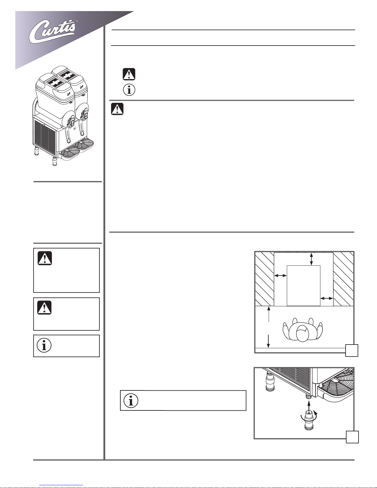
1. Select the location. The unit must be installed
indoors away from sources of moisture and heat.
The clearances shown are the minimum distances
from obstructions, between CFB units and other
equipment, required for proper operation. Do not
obstruct the ventilation grills on the back and sides.
Locate the unit on a secure, level surface. Install the
unit for easy removal if service is needed.
2. Unpack the unit. Keep the original packaging
materials in the event the unit needs to be returned
to the manufacturer.
IMPORTANT: RMAs will not be accepted unless the unit
is packaged in the original packaging material.
3. Locate the legs, packaged inside the bowls. Thread
them into the mounts on the bottom of the unit.
Hand tighten into place.
continued...
4" min.*
(10 cm)
CFB
frozen
beverage
dispenser
(10 cm)
4" min.*
60" min.
(150 cm)
*9" (23 cm) recommended
4" min.*
(10 cm)
1
3
READ AND SAVE THESE INSTRUCTIONS
Page 1
Page 2
Wilbur Curtis Co., Inc.
SETUP INSTRUCTIONS (CONT.)
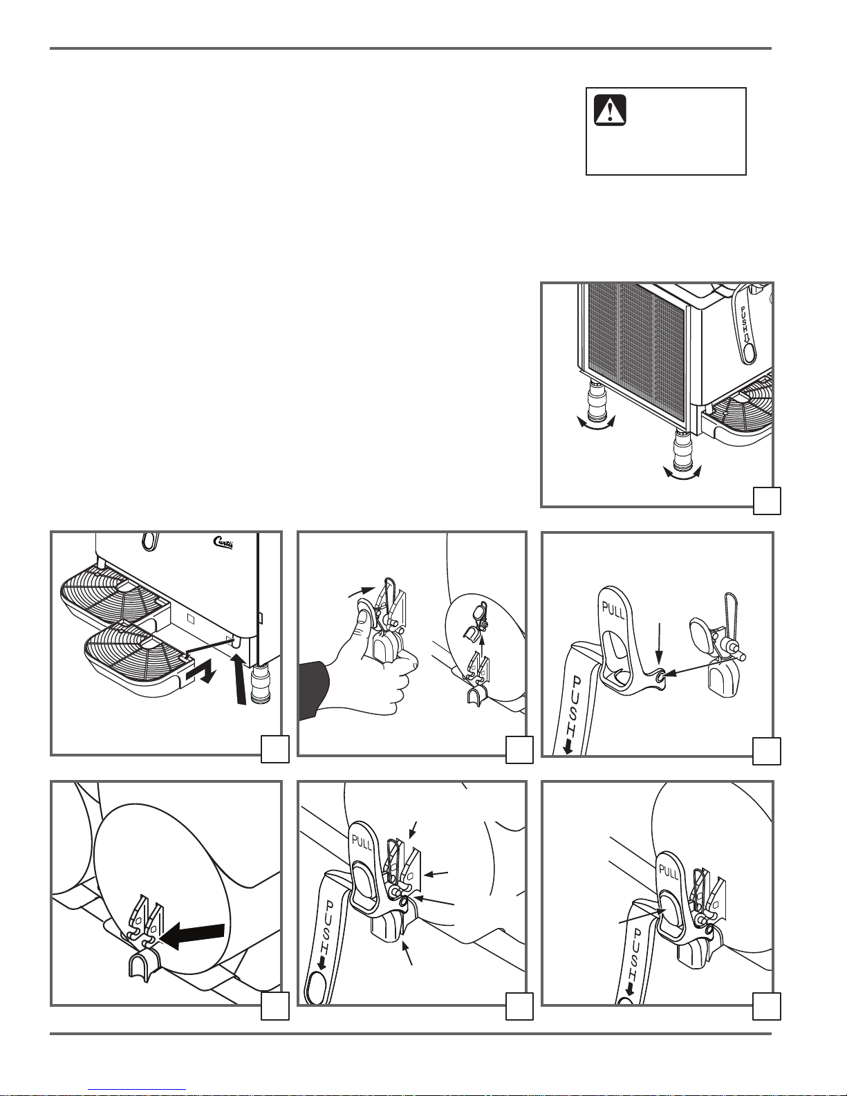
4. Level the unit left to right and front to back by rotating the feet on the bottom of
the legs.
5. Locate the drip trays, packaged inside the bowls. Position the drain hose in the
opening in the top of each tray. Then, insert the tabs on the back of the drip tray
into the holes on the front of the chassis. Push down gently to secure in place.
6. Prepare to install the dispensing levers by removing the handles from the taps.
Push in on the top of the handle with your thumb while pulling up on the bottom
with your index nger.
7. Locate the dispensing levers, packaged inside the bowls. Install them on the tap
handles. While pulling outward on both sides of the base of the dispensing lever,
insert the pins on the bottom of the handle into the base holes on the lever.
8. Lubricate the tap mounting slots using food grade lubricant.
9. Prepare the tap handle assembly for attachment. Lubricate the red rubber gasket
on the back of the tap handle assembly with food grade lubricant and insert it into
the tap hole on the bottom of the bowl. Line up the middle pins on the handle with
the mounting slots.
10. Attach the tap handle assembly. Push in with your thumb on the center of the
handle until the tap handle assembly pops into place.
WARNING: Use the
leveling legs to level
the dispenser only. Do
not use them to adjust unit height.
Do not extend them higher than
necessary.
Drain hose
4
Base
Lever
5
Spring must be
between mounts
Mount
6
Handle
7
8
Page 2
Red plug
(lubricate)
Line up as
shown
9
Push here
10
Page 3
Service Manual - Frozen Beverage Dispenser
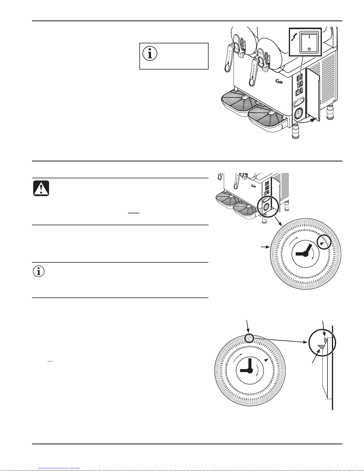
11. Open the control panel door (on the right side) and make sure the
main power switch is in the OFF (O) position.
12. Set the timer clock according to the
instructions below.
13. Connect the unit to a grounded,
3-prong, electrical outlet with the
IMPORTANT: The unit
may not operate as
desired if the timer is not
set properly.
appropriate amperage rating. The circuit
must be protected by a suitably rated circuit breaker. Do not use an
extension cord or any type of adapter.
14. Turn ON (|) the main power switch.
15. Clean and sanitize the unit before using it for the rst time as
instructed in the CLEANING section. Verify that the unit is operating
properly according to the operating instructions.
SETTING THE TIMER CLOCK*
CAUTION:
• Set the timer only with the main power switch in the
OFF (O) position.
• Turn the timer wheel only in the clockwise direction.
• Do not set the timer using any kind of tool.
1. With the main power switch off, turn the outer wheel on the timer
clockwise until the correct time (AM or PM) lines up with the arrow on
the clock face.
2. Turn on the main power switch to start the clock.
IMPORTANT: The clock/timer is equipped with a backup circuit
and continues to keep time for 10 to 15 minutes after power is
interrupted. If the power cord is disconnected or the main power
switch is turned off for a longer period of time, the clock will need
to be reset when power is restored.
Main Power Switch Location
Turn outer wheel
clockwise to set
1
12
2
3
4
5
AM
7
9
8
9
10
11
11
12
12
10
9
8
3
5
6
1
4
3
2
Clock Set to 9:05 PM
7
PM
TIMER OPERATION*
Use the timer to start the unit automatically. This feature allows you to pour
the mix in ahead of time and have the frozen beverage ready to serve at
the programmed time (unattended operation). The timer determines when
the unit is in standby (night) mode or freeze mode. In standby mode the
mixture is kept cool, but does not freeze.
The unit comes from the factory set for manual (non-timer) operation.
When all of the timer tabs are ipped outward (see diagram, right),
the timer is disabled and the unit will freeze the mixture any time the
refrigeration switch is set to ON (|).
Setting Up the Timer
1. With the main power switch off, ip the timer tabs next to the time
marks on the timer to either the standby or freeze position. The unit
will operate in the mode selected during the corresponding time
period.
2. Check to make sure the clock is set to the current time, then turn ON
(|) the main power switch.
*Models CFB2 and CFB3 only.
Timer tabs
2
3
4
5
AM
7
9
8
9
10
11
Timer tab in
freeze position
1
12
11
12
12
10
9
8
7
PM
Timer tab
in standby
(night)
position
3
5
6
1
4
3
2
Timer Side View
Page 3
Page 4

OPERATING INSTRUCTIONS
WARNING:
• Keep body parts and other items clear of the inside of the mixing bowl when the main power switch is
ON (|). Keep the mixing switch in the OFF (O) position whenever the mixing bowl lid is removed.
• Do not use the machine to freeze water alone.
• Use only slush mixtures with the required sugar content (see below).
• Do not use this unit with milk/dairy based mixes unless it is equipped
with a temperature display. Do not leave milk/dairy based mixtures in
the unit without the main power switch on and the refrigeration switch
set to standby (|) or freeze (||).
• Never pour hot liquids (above 77°F/25°C) into the mixing bowl.
• Do not ll the mixing bowl higher than the MAX LEVEL indicator.
Wilbur Curtis Co., Inc.
Temperature
display
Concentrate
Water
MAX
LEVEL
1. If using the unit to dispense a slush type frozen beverage, dilute and mix the
slush concentrate with water in a clean container. Follow the concentrate
manufacturer’s directions. THE MIXTURE OBTAINED MUST HAVE A
MINIMUM SUGAR CONTENT OF 13°Bx and less than 22°Bx (11 to 20% sugar
by weight). The capacity of each mixing bowl is 3 gallons (12 liters). If using the
unit to dispense a milk/dairy based frozen beverage, use the mix according to
the instructions on the package.
2. With the mixing switch in the OFF (O) position, remove the
mixing bowl lid from the desired bowl and hang it on the side.
Pour in the mix up to, or below the MAX LEVEL indicator. The
minimum level is just above the plastic mixing auger.
3. Replace the mixing bowl lid.
1
4. Make sure that the main power switch is ON (|). Push (|) on
the mixing switch for the desired mixing bowl to turn on the
mixer.
5. Push (|) on the refrigeration switch for the desired mixing
bowl to begin freezing. NOTE: On units equipped with a
timer, when the refrigeration switch is in position (|), the unit
will freeze the mixture provided the timer is set to freeze
for the current time (see Setting the Timer). Standby mode,
position (||) on the refrigeration switch, may be used to put
the unit in standby mode manually. This mode saves energy,
keeping the mixture cool without freezing.
Mixing
Refrigeration
2
3
Page 4
4
5
Page 5
Service Manual - Frozen Beverage Dispenser
MAX
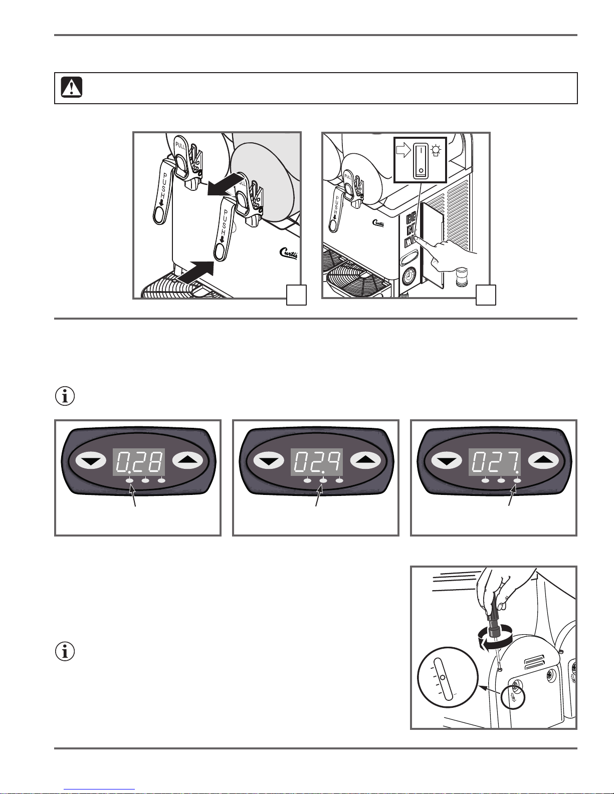
6. Once the mixture is frozen (40 to 90 minutes), pull out on the top of the dispenser lever or push the bottom of the lever to
dispense.
CAUTION: If the tank is lled with a milk or dairy based mix, dispense a small amount of the product from the tap into a separate
container before dispensing the serving for the customer.
7. Push (|) on the light switch to turn on the integral lid lights.
or
6
7
How to Read the Digital Temperature Display (Some Versions)
The temperature display indicates the temperature in the mixing bowls. The display changes every three seconds to show
the temperature in a different bowl. The dot at the bottom of the display indicates the bowl temperature that is currently being
displayed. See the diagrams below for more information. The bowls are numbered 1, 2 and 3*, left to right, facing the front.
NOTE: If the display shuts off, it can be reset by pushing the down arrow button (▼).
1 2 3 1 2 31 2 3
Bowl 1 display
indicator
Bowl 2 display
indicator
Bowl 3 display
indicator*
*CFB3 only
Adjusting Beverage Thickness
Use the adjustment screws at the back of each mixing bowl to adjust beverage
thickness. The recommended (factory default) setting is 2. Insert a at blade
screwdriver into the adjustment hole as shown and turn to adjust. The indicator on the
back will move to indicate the thickness level. The higher the number the thicker the
frozen beverage will be.
IMPORTANT: When the thickness level is set to higher levels, (around 4) the lid
should be fastened to prevent it from coming off during operation.
1
2
Periodic maintenance
Have the unit checked periodically (at least once a year) by a qualied technician to
ensure proper operation.
3
MAX
4
1
2
3
MAX
4
Back
1
2
3
4
Page 5
Page 6
Wilbur Curtis Co., Inc.
CLEANING
WARNING:
• To avoid personal injury, disconnect the power cord before cleaning. Wear protective glasses and
gloves.
• Never spray water on the unit to clean it.
• Do not use cleaning liquids, compounds or powders containing chlorine (bleach), solvents, scouring
powder,
ammable materials or corrosives. These products promote corrosion and will damage the
surfaces. USE OF THESE PRODUCTS WILL VOID THE WARRANTY.
• DO NOT immerse the unit or parts in water or any other liquid, unless specically instructed to do so.
Do not wash any of the components in a dishwasher. Hand or air dry the parts only.
Daily Cleaning
Clean and sanitize all of the bowl assemblies at least once a day according to the following steps. These operations may need to
be performed more frequently based on the mix used. Contact the concentrate/mix supplier for more details. If the machine is not
used continuously throughout the day, wipe the tap areas with a clean cloth and sanitizing uid. If the dispenser has not been used
for a long period of time, clean the unit before returning it to use.
1. For cleaning, prepare a mild solution of detergent and warm water.
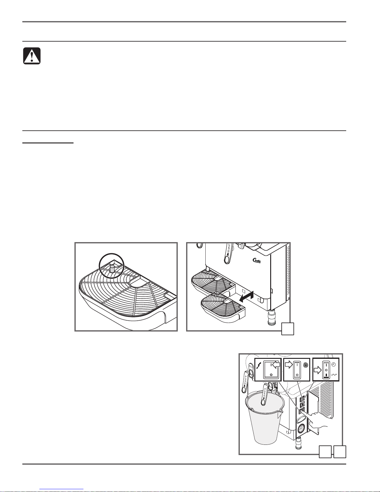
Empty the Drip Trays
The drip trays should be emptied and cleaned every day and drained every time the red full indicator pops up. They must also be
removed before emptying the bowl.
2. Lift each drip tray up and out.
3. Wash the trays and grills with the detergent solution. Hand dry all of the components, then reinstall the grills. Set the trays aside
and reinstall at the end of the daily cleaning process.
Full indicator
2
Empty the Bowl
Empty each bowl before cleaning (if already empty, skip to step 7).
4. Place a large empty container under each dispenser tap.
5. Turn the main power switch to the ON (|) position. Turn the mixing switches to
the ON (|) and the refrigeration switches to the OFF (O) position. Pull out on each
dispenser lever to drain the contents out of each bowl. NOTE: If the beverage
mixture is not frozen, hold the container up to the bottom of the tap to reduce
splashing.
6. Once the bowls are empty, switch the main power switch OFF (O). Unplug the
power cord from the electrical outlet.
Page 6
54
Page 7
Service Manual - Frozen Beverage Dispenser
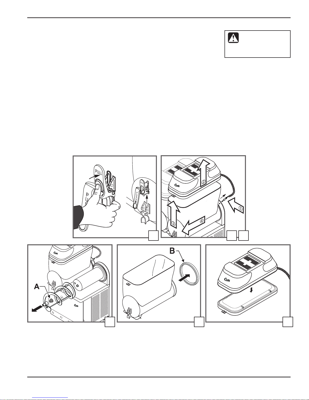
Remove the Mixing Bowls and Lids
7. Remove the handle assembly from the bowl tap by pushing in on the top of the handle with
your thumb while pulling up on the bottom with your index nger.
8. Disconnect the lid light plugs from the sockets behind the mixing bowl. Make sure that the
plugs do not come into contact with liquids while removed. Lift off the lids.
9. Raise the front part of each bowl to release. Remove each bowl from its seat by pushing and
tapping lightly on the rear.
NOT immerse the top portion of
the lid in uids of any kind.
CAUTION:
To prevent damage, DO
Clean the Mixing Bowl Parts
10. Pull forward on each auger to remove it from the evaporator. Remove the auger seal (A).
11. Pull the bowl seal (B) off of the back of the bowl.
12. Pull the bottom part of the lids free from the top parts.
13. Soak the bottom part of the lids, removed in step 12, and the tap parts and auger in detergent solution and scrub with a soft
cloth. Rinse in fresh water.
14. To clean the top portions (lighted part) of the lids, use a clean, damp cloth soaked with detergent solution. Using a clean, damp
cloth, wipe clean the outside portion of the lid top. Wipe with a clean, damp cloth soaked in fresh water.
15. Clean the mixing bowls and evaporators with a clean damp cloth soaked with detergent solution. Wipe with a clean, damp cloth
soaked in fresh water.
continued...
987
10 11 12
Page 7
Page 8
Wilbur Curtis Co., Inc.
Daily Cleaning (Cont.)
Sanitizing
16. Fill a container with a sanitizer solution mixed in water (2% of sodium hypoclorite mixed in water).
17. Using a sponge dipped in sanitizing solution, sanitize the underside of the bottom portion of the lids. Allow 30 minutes for the
solution to act.
18. Rinse the underside of the lid bottoms with a clean sponge soaked in fresh water. Place the lids on a clean surface and hand
dry, rst the underside, then the outside, using a clean cloth.
19. Thoroughly wash the bowl and evaporator with a sponge soaked in the sanitizer solution. Rinse thoroughly with clean water.
20. Fill another container with sanitizer solution and submerge the tap parts, augers and seals in the sanitizer solution. Leave them
to soak in the solution for 30 minutes. Rinse thoroughly with clean water, then air dry.
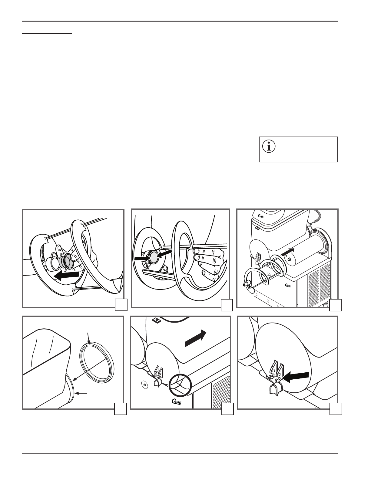
Reassemble the Unit
21. Check the seals before reinstalling. Replace worn seals with new ones before reinstalling. Replace all seals and gaskets at
least once a year.
22. Install each auger seal on each auger.
23. Using food grade lubricant, lubricate the inside of the auger seal.
24. Reinstall the augers. Rotate each auger until it engages completely.
25. Install an evaporator seal on the back of each bowl. The circular lip on the back of the bowl ts into the groove on the seal.
26. Set the mixing bowls back in place. Make sure that the lip on the bottom of each bowl rests inside the front trim on the top of
the chassis.
27. Lubricate the tap mounting slots on the front of each mixing bowl with food grade lubricant.
gaskets may result in leaks.
IMPORTANT: Failure to
properly lubricate seals/
22
Seal
groove
Lip
25 26 27
Page 8
23 24
Page 9

Service Manual - Frozen Beverage Dispenser
28. Prepare the tap handle assembly for attachment. Check the red rubber gasket on the back of each tap assembly for wear.
Replace if necessary. Lubricate each tap gasket with food grade lubricant. Insert the gasket into the tap hole on the bottom of
the bowl. Line up the middle pins on the handle with the mounting slots.
29. Attach the tap handle assembly. Push in with your thumb on the center of the handle until the handle assembly pops into place.
30. Reassemble and reinstall each lid and insert the light plug into the socket behind each mixing bowl.
Rinse the Unit
Before starting up the unit again after cleaning, rinse it out as follows:
31. Connect the power cord to the electrical outlet.
32. Fill the mixing bowls with clean water;
33. Turn the main power switch to the ON (|) position. Push (|) on the mixing switches for all of the mixing bowls. Make sure the
refrigeration switches are OFF (O).
34. Leave the unit on for ve minutes.
35. Drain the water from each of the mixing bowls by placing a container under the tap and pulling the lever.
Reinstall the Drip Trays and Wipe Up
36. Position the drain hose in the opening
in the top of each tray. Then, insert the
tabs on the back of the drip tray into
the holes on the front of the chassis.
Push down gently to secure in place.
37. Wipe any dust or debris from the
exterior surfaces of the unit with a
damp cloth. Wipe up any spills/liquids
in the surrounding area.
Spring must be
between mounts
Mount
Line up as
shown
Push here
Red gasket
(lubricate)
Weekly Cleaning
1. Make sure the main power switch is in the OFF (O) position.
2. Lift the lter* up and out of the slot on the left side of the unit.
3. Clean the lter and the ventilation louvers on the outside of the unit with a
vacuum or soft bristled brush.
4. Replace the lter.
*Model CFB1 is not equipped with a lter.
28
3533
29
Drain hose
3630
Page 9
Page 10

TROUBLESHOOTING
Wilbur Curtis Co., Inc.
Unit Does Not Turn ON
1. Make sure that the circuit breaker for the electrical
outlet is not tripped and is turned on.
2. Make sure that the power cord is properly
connected to the electrical outlet.
3. Make sure that the main power switch is on.
Mixture Does Not Freeze
1. Make sure that the refrigeration switch is in the (|)
position.
2. If using a slush mixture, make sure that it is properly
diluted. Proper sugar content is 11 - 20%.
3. Make sure that the clock is set to the current time
and that the timer is set to freeze at the current time.
See "SETTING THE TIMER CLOCK" (CFB2 and
CFB3 only).
4. Make sure that the thickness setting is not set too
low. See "Adjusting Beverage Thickness".
5. See "Check for Proper Ventilation" section on the
facing page.
6. Check to see if the compressor reset switch inside
the control panel is "popped out" (CFB2 and CFB3
without temperature display only). Push in to reset
(see diagram below) and allow the sealed system
to cool before restarting the unit. If the reset switch
continues to pop out, call for service.
Tap Leaks
1. Make sure that the (red) tap gasket is properly
lubricated and is not worn out.
2. Make sure that the tap handle assembly is properly
seated.
Beverage Does Not Come Out of Tap
This problem is usually caused by a mixture that is too
thick or ice chunks forming in the bowl.
1. If using a slush mixture, make sure that it is properly
diluted. Proper sugar content is 11 - 20%.
2. Make sure the thickness setting on the back of unit
is not set too high.
Leak at Back of Mixing Bowl
1. Make sure that the mixing bowl seal is properly
lubricated and is not worn out.
2. Make sure that the mixing bowl is properly seated.
Auger Does Not Turn or is Noisy
1. Make sure the mixing switch is turned on.
2. If using a slush mixture, make sure that it is
properly diluted. Proper sugar content is 11 - 20%.
An improperly diluted slush mixture can cause
ice chunks that can interfere with proper auger
operation.
3. Make sure the auger seal is properly installed and
lubricated.
Compressor Reset (some models)
Page 10
High Pressure/Temperature Light On
CFB2 and CFB3 only. Turn
off the main power switch*
and check the following:
1. See "Check for Proper
Ventilation" section on
the facing page.
2. If the light still comes
on during operation,
turn off the main power
switch and call for
service.
* On units equipped with a temperature display, the
system is designed to reset itself automatically after the
main power switch has been off for 5 minutes.
High pressure/
temperature light
Page 11

Service Manual - Frozen Beverage Dispenser
TROUBLESHOOTING
Numeric Code (Alarm) Appears on Display
CFB2 and CFB3 with temperature display only. See list
below to determine possible problem.
Error
Code
A1
A2
A3
A4
A5
A6
Problem Remedy
Temperature probe
for bowl 1
disconnected
Bowl 1 too hot or
temperature probe
shorted
Temperature probe
for bowl 2
disconnected
Bowl 2 too hot or
temperature probe
shorted
Temperature probe
for bowl 3 (CFB3
only) disconnected
Bowl 3 (CFB3 only)
too hot or tempera-
ture probe shorted
See "Check for Proper
ventilation is OK, call
See "Check for Proper
ventilation is OK, call
See "Check for Proper
ventilation is OK, call
Call for service
Ventilation". If
for service..
Call for service
Ventilation". If
for service.
Call for service
Ventilation". If
for service.
Check for Proper Ventilation:
1. The unit will not function properly if there is not
sufcient air space (4 inches minimum on back and
sides).
2. Make sure that the lter (CFB2 and CFB3 only) is
clean and that all ventilation grills are not blocked or
dirty. See the CLEANING section.
3. Make sure that the unit is not close to sources of
heat that could affect proper operation (heaters,
cooking grills, etc.).
REFRIGERANT SPECIFICATIONS
For reference only. Check the serial number label on the product for the refrigerant specications for the unit being serviced.
CFB1 CFB3
Refrigerant type R404A
Amount 7.05 ounces
High design pressure 397 psig
Low design pressure 175 psig
CFB2
Refrigerant type R404A
Amount 12.84 ounces
High design pressure 397 psig
Low design pressure 175 psig
Refrigerant type R404A
Amount 16.68 ounces
High design pressure 397 psig
Low design pressure 175 psig
Page 11
Page 12

ROUGH-IN DIAGRAMS
CFB1
Wilbur Curtis Co., Inc.
11.75”
(29.8 cm)
SIDE VIEW
8.82”
(22.4 cm)
35.51”
(90.2 cm)
FRONT VIEW
TOP VIEW
20.48”
(52.0 cm)
8.15”
(20.7 cm)
4.21”
(10.7 cm)
5.91”
(15.0 cm)
CFB2
11.74”
(29.8 cm)
SIDE VIEW
35.51”
(90.2 cm)
FRONT VIEW
TOP VIEW
19.53”
(49.6 cm)
16.49”
(41.9 cm)
4.21”
(10.7 cm)
11.69”
(29.7 cm)
Page 12
12.60”
(32.0 cm)
Page 13

ROUGH-IN DIAGRAMS
CFB3
Service Manual - Frozen Beverage Dispenser
11.75”
(29.8 cm)
SIDE VIEW
11.69”
(29.7 cm)
35.51”
(90.2 cm)
FRONT VIEW
9.76”
(24.8 cm)
4.21”
(10.7 cm)
10.71”
(27.2 cm)
11.30
(28.7 cm)
TOP VIEW
19.57”
(49.7 cm)
24.53”
(62.3 cm)
Page 13
Page 14

WIRING DIAGRAMS
Wilbur Curtis Co., Inc.
1
N
Power Consumption:
115 Vac, 60 Hz., 8.1 A
2 3
M
9
M
WIRING DIAGRAM - MODEL CFB1
M
6
FA3
5
FA2
7
11
8
tº
12
10
M
4
13
Page 14
Nº Description
1 Main power switch
2
Auger motor
3 Fan motor
4 Tank cover light
5 Relay
6 Micro regulation
7 Refrigeration switch
Nº Description
8 Thermostat
9 Fan motor
10 Compressor
11 Tank lights switch
12 Transformer
13 Fuse
LEGEND - MODEL CFB1
Page 15

WIRING DIAGRAMS
1
L
P
24
Service Manual - Frozen Beverage Dispenser
11
10
17
23
3
N
Power Consumption:
115 Vac, 60 Hz., 12.4 A
M
2
67
M
13
5
M
4
14
15
16
12
M
8 8
tº tº
WIRING DIAGRAM - MODEL CFB2 WITHOUT TEMPERATURE DISPLAY
18 9
M
19
20
21
22
Nº Description
1 Main power switch
2
Fuse
3 Compressor
4 Fan motor
5 Transformer
6 Tank cover light
7 Fuse
8 Relay
9 Timer
10 Tank lights switch
11 Left mixing switch
12 Left refrigeration switch
LEGEND - MODEL CFB2 WITHOUT TEMPERATURE DISPLAY
Nº Description
13 Left auger motor
14 Left thermostat
15 Left micro regulation
16 Left electrovalve
17 Right mixing switch
18 Right refrigeration switch
19 Right auger motor
20 Right thermostat
21 Right micro regulation
22 Right electrovalve
23 Relay
24 Compressor cutoff (reset) switch
Page 15
Page 16

WIRING DIAGRAMS
1
F
T
FA3
COM
23
NO
FA1 FA2
3
M
Wilbur Curtis Co., Inc.
24
10
2
7
5
6
M
4
M
11
12
13
8
tº tº
14
M
20
17
19
18 9
M
8
tº
25
N
Power Consumption:
115 Vac, 60 Hz., 12.4 A
Nº Description
1 Main power switch
Fuse holder
2
3 Compressor
4 Fan motor
5 Transformer
6 Tank cover light
7 Fuse
8 Relay
9 Timer
10 Tank lights switch
11 Left mixing switch
12 Left refrigeration switch
13 Left auger motor
15
16
21
22
WIRING DIAGRAM - MODEL CFB2 WITH TEMPERATURE DISPLAY
Nº Description
14 Left thermostat
15 Left micro regulation
16 Left electrovalve
17 Right mixing switch
18 Right refrigeration switch
19 Right auger motor
20 Right thermostat
21 Right micro regulation
22 Right electrovalve
23 Electronic Regulator
24 Thermal Protector
25 Temperature Display
tº
LEGEND - MODEL CFB2 WITH TEMPERATURE DISPLAY
Page 16
Page 17

WIRING DIAGRAMS
1
L
30
P
29
3
M
2
M
4
M
Service Manual - Frozen Beverage Dispenser
23
24
M
8
25
26
9
M
8
12
17
18
M
19
8
20
11
10
7
31
6
M
13
5
tº tº tº
14
N
Power Consumption:
115 Vac, 60 Hz., 14.8 A
15
16
21
22
WIRING DIAGRAM - MODEL CFB3 WITHOUT TEMPERATURE DISPLAY
Nº Description
1 Main power switch
2 Fan motor 1
3 Compressor
4 Fan motor 2
5 Transformer
6 Tank cover light
7 Fuse
8 Relay
9 Timer
10 Tank lights switch
11 Left mixing switch
12 Left refrigeration switch
13 Left auger motor
14 Left thermostat
15 Left micro regulation
Nº Description
17 Middle mixing switch
18 Middle refrigeration switch
19 Middle auger motor
20 Middle thermostat
21 Middle micro regulation
22 Middle electrovalve
23 Right mixing switch
24 Right refrigeration switch
25 Right auger motor
26 Right thermostat
27 Right micro regulation
28 Right electrovalve
29 Relay
30 Compressor cutoff (reset) switch
31 Fuse
16 Left electrovalve
27
28
LEGEND - MODEL CFB3 WITHOUT TEMPERATURE DISPLAY
Page 17
Page 18

WIRING DIAGRAMS
1
L
T
30
FA3
COM
29
NO
FA1 FA2
3
M
M
2
4
M
Wilbur Curtis Co., Inc.
11
10
6
7
31
12
M
13
5
tº
14
17 23
M
19
8
tº tº
20
18
M
8
26
24
25
9
M
8
tº
32
N
Power Consumption:
115 Vac, 60 Hz., 14.8 A
Nº Description
1 Main power switch
2 Fan motor 2
3 Compressor
4 Fan motor 1
5 Transformer
6 Tank cover light
7 Fuse
8 Relay
9 Timer
10 Tank lights switch
11 Left mixing switch
12 Left refrigeration switch
13 Left auger motor
14 Left thermostat
15 Left micro regulation
16 Left electrovalve
15
16
21
22
27
28
WIRING DIAGRAM - MODEL CFB3 WITH TEMPERATURE DISPLAY
Nº Description
17 Middle mixing switch
18 Middle refrigeration switch
19 Middle auger motor
20 Middle thermostat
21 Middle micro regulation
22 Middle electrovalve
23 Right mixing switch
24 Right refrigeration switch
25 Right auger motor
26 Right thermostat
27 Right micro regulation
28 Right electrovalve
29 Electronic regulator
30 Thermal protector
31 Fuse holder
32 Temperature Display
tº
tº
LEGEND - MODEL CFB3 WITH TEMPERATURE DISPLAY
Page 18
Page 19

20
23
5
16
27A
40A
33
35
34
37
41
32
15
29
44
38
42
43A
45A
30
8
11
12
6
25A
48
17
24
18
49
24
51
4
14
19
26
28A
22
EXPLODED VIEW - CFB1
Service Manual - Frozen Beverage Dispenser
Page 19
Page 20

16
32
33
30
29
43B
42
38
20
44
41
37
35
34
40B
28A
50
54
56
27B
48
17
49
24
19
18
45B
51
21
24
36
39
31
15
25B
53
14
10
9
7
55A
13
23
47A
47B
46A
46B
22
8
11
12
6
26
EXPLODED VIEW - CFB2
Wilbur Curtis Co., Inc.
Page 20
Page 21

10
20
43B
25
42
41
38
44
35
34
37
15
31
29
30
33
32
16
9
28B
47A
55B
47B
25B
51
21
13
39
36
7
17
18
24
49
24
48
53
23
52
19
46C
46D
40C
27C
5
45B
8
11
12
6
14
26
22
54
56
EXPLODED VIEW - CFB3
Service Manual - Frozen Beverage Dispenser
Page 21
Page 22

Wilbur Curtis Co., Inc.
PARTS LIST
ITEM PART # DESCRIPTION
a
1
a
2
a
3
4 WC-100151 ELECTRONIC REGULATOR (CFB1)
5 WC-100129 FAN MOTOR 120X120X38 115V CFB3 (ALSO USED ON CFB1)
6 WC-100005 TRANSPARENCY (CFB1, CFB2, CFB3)
a
7
a
8
a
9
a
10
a
11
12 WC-100011 DISPENSING LEVER PUSH - BLACK (CFB1, CFB2, CFB3)
a
13
a
14
a
15
a
16
a
17
a
18
a
19
20 WC-4916 LUBRICANT, GREASE HEAVY DUTY PC'S 4oz (CFB1, CFB2, CFB3)
a
21
22 WC-100024 BOWL COVER SET GT - BLACK (COMPLETE) (CFB1, CFB2, CFB3)
a
23
a
24
25A WC-100147 COMPLETE TRANSFORMER (CFB1)
25B WC-100079 COMPLETE TRANSFORMER (CFB2, CFB3)
a
26
a
27A
a
27B
a
27C
a
28A
a
28B
a
29
a
30
a
31
a
32
a
33
a
34
a
35
a
36
a
37
a
38
a
39
40A WC-100143 COMPRESSOR (CFB1)
40B WC-100071 COMPRESSOR (CFB2)
40C WC-100119 COMPRESSOR (CFB3)
a
Recommended parts to stock
WC-100130 TUNE UP KIT 1 BOWL (NOT SHOWN, INCLUDES ITEMS 11, 29 AND 32)
WC-100127 TUNE UP KIT 2 BOWLS (NOT SHOWN, INCLUDES ITEMS 11, 29 AND 32)
WC-100128 TUNE UP KIT 3 BOWLS (NOT SHOWN, INCLUDES ITEMS 11, 29 AND 32)
WC-100103 MECHANICAL TIMER (CFB2, CFB3)
WC-100001 TAP SET GNW - BLACK (ADA-LONG HANDLE) (CFB1, CFB2, CFB3)
WC-100097 CUT OFF PRESSURE CFB (CFB2, CFB3 WITHOUT TEMPERATURE DISPLAY)
WC-100094 FILTER EXT. CONDENS. COMP. USA 05 CFB (CFB2, CFB3)
WC-100010 TAP RUBBER GASKET - RED (CFB1, CFB2, CFB3)
WC-100109 RELE FINDER 60.63 110V/60HZ (10A) (CFB2, CFB3 WITHOUT TEMPERATURE DISPLAY)
WC-100013 TAP LOCK ROD - BLACK (CFB1, CFB2, CFB3)
WC-100088 FUSE 5A (CFB1, CFB2, CFB3)
WC-100015 SPIRAL SHOVEL (CFB1, CFB2, CFB3)
WC-100087 SWITCH PROTECTION 22 X 30 (CFB1, CFB2, CFB3)
WC-100086 SWITCH PROTECTION 11 X 30 (CFB1, CFB2, CFB3)
WC-100018 DRIPPING TRAY+GRATING GT BLACK (CFB1, CFB2, CFB3)
WC-100023 RELAY (30 AMP) (CFB2, CFB3)
WC-100025 COMMAND COVER+ TECH SUPPORT ADH + HINGES+ SCREWS (CFB1, CFB2, CFB3)
WC-100084 SWITCH-BLACK (CFB1, CFB2, CFB3)
WC-100028 BOWL SET GNW (CFB1, CFB2, CFB3)
WC-100146 COMPRESSOR RELAY (CFB1)
WC-100076 COMPRESSOR RELAY (CFB2)
WC-100120 COMPRESSOR RELAY CFB3
WC-100075 POWER CABLE (CFB1, CFB2)
WC-100171 POWER CABLE (CFB3)
WC-100031 TANK JOINT (CFB1, CFB2, CFB3)
WC-100106 WATERTIGHT 2 M6+OR EVAP GHZ-GB (COMES WITH O-RINGS INSTALLED) (CFB1, CFB2, CFB3)
WC-100074 FAN MOTOR 16W 115/60 (CFB2, CFB3)
WC-100034 WATERTIGHT SHAFT JOINT SIL. TRANSLU. (SEAL) (CFB1, CFB2, CFB3)
WC-100035 UPPER TRAY CAP - BLACK (CFB1, CFB2, CFB3)
WC-100036 REGULATION SYSTEM SUBJECTION (ADJUSTMENT PIN RETAINER) (CFB1, CFB2, CFB3)
WC-100037 REGULATION ROD (CFB1, CFB2, CFB3)
WC-100073 SPECIAL NUT TYPE CWP M4 (CFB2, CFB3)
WC-100039 REGULATION SYSTEM SPRING GUIDE (CFB1, CFB2, CFB3)
WC-100040 GEAR MOTOR ELCO MONO 115/60HZ (CFB1, CFB2, CFB3)
WC-100072 FAN MOTOR BLADES Ø250 X 28º (CFB2, CFB3)
Page 22
Page 23

Service Manual - Frozen Beverage Dispenser
PARTS LIST (CONT.)
ITEM PART # DESCRIPTION
a
41
a
42
43A WC-100136 EVAPORATOR SUPPORT SET PZ-1+ PZ-2 - BLACK (CFB1)
43B WC-100045 EVAPORATOR SUPPORT SET PZ-1+ PZ-2 - BLACK (CFB2, CFB3)
a
44
45A WC-100141 CONDENSER + FILTER (CFB1)
45B WC-100069 CONDENSER + FILTER (CFB2, CFB3)
46A WC-100065 DOUBLE ELECTROVALVE OLAB 115V/60HZ (CFB2)
46B WC-100066 DOUBLE ELECTROVALVE CEME 115V/60HZ) (CFB2)
46C WC-100115 TRIPLE ELECTROVALVE CEME 115V/60HZ CFB3
46D WC-100116 TRIPLE ELECTROVALVE OLAB 115V/ 60HZ CFB3
47A WC-100063 GAS ELECTROVALVE BOBBIN OLAB 1 (CFB2, CFB3)
47B WC-100064 GAS ELECTROVALVE BOBBIN CEME 1 115V 60HZ (CFB2, CFB3)
a
48
a
49
a
50
a
51
52 WC-100123 COMPRESSOR OPERATION BOX (CFB3)
53 WC-100100 DRAIN RACOR (DRAIN PIPE FITTING) (CFB1, CFB2, CFB3)
54 WC-100187 ELECTRONIC REGULATOR (CFB2, CFB3 WITH TEMPERATURE DISPLAY)
55A WC-100191 ELECTRONIC TEMPERATURE VISUAL DISPLAY (CFB2 WITH TEMPERATURE DISPLAY)
55B WC-100192 ELECTRONIC TEMPERATURE VISUAL DISPLAY (CFB3 WITH TEMPERATURE DISPLAY)
56 WC-100186 THERMAL PROTECTOR (CFB2, CFB3 WITH TEMPERATURE DISPLAY)
a
Recommended parts to stock
WC-100043 REGULATION SPRING (CFB1, CFB2, CFB3)
WC-100044 TRANSMISSION SHAFT SET (CFB1, CFB2, CFB3)
WC-100046 MINIRRUPTOR (CONTROL SWITCH) (CFB1, CFB2, CFB3)
WC-100061 GREEN MAIN SWITCH (CFB1, CFB2, CFB3)
WC-100060 SWITCH-BLACK (CFB1, CFB2, CFB3)
WC-100078 COMPRESSOR CAPACITOR (CFB2)
WC-100057 MECHANICAL THERMOSTAT (CFB1, CFB2, CFB3 WITHOUT TEMPERATURE DISPLAY)
Page 23
Page 24

Product Warranty
Wilbur Curtis Co., Inc. certies that its products are free from defects in material and workmanship under normal use. The following limited warranties
and conditions apply:
5 years, parts and 1 year labor, from the original date of purchase on compressors on refrigeration equipment
3 years, parts and labor, from original date of purchase on digital control boards
2 years, parts, from original date of purchase on all other electrical components, ttings and tubing
1 year, labor, from original date of purchase on all other electrical components, ttings and tubing
Additionally, Wilbur Curtis Co., Inc. warrants its grinding burrs for forty (40) months from the date of purchase or 40,000 pounds of cof fee, whichever
comes rst. Stainless steel components are warranted for two (2) years from the date of purchase against leaking or pitting. Replacement parts
are warranted for ninety (90) days from the date of purchase or for the remainder of the limited warranty period of the equipment in which the
component is installed.
All in-warranty service calls must have prior authorization. For authorization, call the Technical Support Department at 800-995-0417.
Additional conditions may apply. Go to www.wilburcurtis.com to view the full product warranty information.
CONDITIONS & EXCEPTIONS
The warranty covers original equipment at time of purchase only. Wilbur Curtis Co., Inc., assumes no responsibility for substitute replacement parts
installed on Curtis equipment that have not been purchased from Wilbur Curtis Co., Inc. Wilbur Curtis Co., Inc. will not accept any responsibility if
the following conditions are not met. The warranty does not cover:
• Adjustments and cleaning: The resetting of safety thermostats and circuit breakers, programming and temperature adjustments are the
responsibility of the equipment owner. The owner is responsible for proper cleaning and regular maintenance of this equipment.
• Replacement of items subject to normal use and wear: This shall include, but is not limited to, spray heads, light bulbs, shear disks,
“O” rings, gaskets, silicone tubing, canister assemblies, whipper chambers and plates, mixing bowls, agitation assemblies and whipper propellers.
The warranty is void under the following circumstances:
• Improper operation of equipment: The equipment must be used for its designed and intended purpose and function.
• Improper installation of equipment: This equipment must be installed by a professional technician and must comply with all local electrical,
mechanical and plumbing codes.
• Improper voltage: Equipment must be installed at the voltage stated on the serial plate supplied with this equipment.
• Improper water supply: This includes, but is not limited to, excessive or low water pressure and inadequate or uctuating water ow rate.
• Damaged in transit: Equipment damaged in transit is the responsibility of the freight company and a claim should be made with the carrier.
• Abuse or neglect (including failure to periodically clean or remove lime accumulations): The manufacturer is not responsible for variation
in equipment operation due to excessive lime or local water conditions. The equipment must be maintained according to the manufacturer’s
recommendations.
Repairs and/or Replacements are subject to Curtis’ decision that the workmanship or parts were faulty and the defects showed up under normal
use. All labor shall be performed during regular working hours. Overtime charges are the responsibility of the owner. Charges incurred by delays,
waiting time, or operating restrictions that hinder the service technician’s ability to perform service is the responsibility of the owner of the equipment.
This includes institutional and correctional facilities. Wilbur Curtis Co., Inc. will allow up to 100 miles, round trip, per in-warranty service call.
Return Merchandise Authorization (RMA): All claims under this warranty must be submitted to the Wilbur Curtis Technical Support Department
prior to performing any repair work or return of this equipment to the factory. All returned equipment must be properly re-packaged in the
original carton and received by Curtis within 45 days following the issuance of a RMA. No units will be accepted if they are damaged in
transit due to improper packaging. NO UNITS OR PARTS WILL BE ACCEPTED WITHOUT A RETURN MERCHANDISE AUTHORIZATION
(RMA). THE RMA NUMBER MUST BE MARKED ON THE CARTON OR SHIPPING LABEL. All warranty claims must be submitted within
60 days of service. Invoices will not be processed or accepted without a RMA number. Any defective parts must be returned in order
for warranty invoices to be processed and approved. All in-warranty service calls must be performed by an authorized service agent. Call the
Wilbur Curtis Technical Support Department to nd an agent near you.
ECN 19783 Rev F 01/29/18 @ 10.4
Wilbur Curtis Co., Inc.
Mail: 6913 Acco Street, Montebello, CA 90640-5403 U.S.A.
Phone: 800-421-6150 │ Fax: 323-837-2410 │ Technical Support Phone: 800-995-0417 (M-F 5:30
FOR THE LATEST SPECIFICATION INFORMATION GO TO WWW.WILBURCURTIS.COM
a.m. - 4:00 p.m. PST) │ Email: techsupport@wilburcurtis.com │ www.wilburcurtis.com
Printed in U.S.A. 01/18 F-4043 RevF
 Loading...