

Page 1
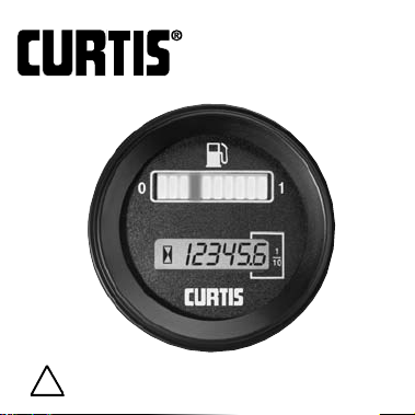
MODEL 2100R &
2200R
Engine Gages
Read Instructions Carefully !
!
Page 2
Safety Instructions
This instrument was manufactured and tested
according to the applicable technical standards.It complies with
all the safety regulations as shipped from the factory.
Installation and startup must be performed by skilled personnel.
Failure to install and operate the unit in accordance with these
instructions may result in damage or injury.
If safe operation of the instrument can no longer be ensured,
stop and secure it against accidental operation.
If instrument failure or malfunction may cause personal injury or
material damage, use additional safety measures such as limit
switches, guards, etc.
Read the Operating Instructions carefully before startup.
Note the safety instructions marked with this
warning symbol in this manual!
!
!
Page 3
TABLE OF CONTENTS Page
1. Safety Instructions 2
2. Model Encodement 3
3.Technical Specifications
3.1 Electrical 5
3.2 Mechanical 8
3.3 Environmental 9
4. Installation 11
5.Troubleshooting 14
6. Maintenance 15
!
!
Page 4

3
2. MODEL ENCODEMENT
(for 2100R/2200R series)
2111RXX-YYYY ZZ
Model Numbers
2111 Temperature
2112 Fuel
2113 Pressure
2114 Voltage
2211 Temperature/Hour
2212 Fuel/Hour
2213 Pressure/Hour
2214 Voltage/Hour
!
Page 5

4
R = case (round)
XX = voltage (DC voltages only)
YYYY = sequential number code
describes gage’s factory programming
ZZ = artwork code (OO = Curtis)
!
Page 6

5
3. TECHNICAL SPECIFICATIONS
3.1 Electrical
Operating V oltage
Model Series 2100R and 2200R are available in either
12VDC or 24VDC (negative ground systems only)
Operating V oltages
(Models 2111R, 2112R, 2113R and 2211R, 2212R, 2213R)
Model Minimum Nominal Maximum
12V 9.0 12.0 16.0
24V 18.0 24.0 32.0
(Models 2114R and 2214R)
Model Minimum Nominal Maximum
12V 8.0 12.0 18.0
24V 16.0 24.0 36.0
Accuracy
Maximum indicator error is less than ±3.5% of full scale
!
Page 7

Operating Current
Total system current is a function of the voltage,
sender type, display mode, and the gage’s factory
programming.Typical operating currents (not
including the current to drive the sender) vary from 16-55 mA,
for 12V models, depending on model number.For 24V models,
typical operating currents (not including the current to drive the
sender) vary from 18-45 mA, depending on model number.
Variable Parameters
The following parameters are set in the factory as part of the
gage’s programming.Contact Curtis for additional information
on your specified model number.
Sender input: Variable resistance
Variable voltage
Variable current
Display mode
Single LED pointer*
Rising bar graph
Transition points for each of the 10 LEDs
(Used to customize display for OEMapplications)
*indicates standard setting
!
6
Page 8

Output signal trigger point (lower)
First LED
Second LED
Output signal trigger point (upper)
Ninth LED
Tenth LED
Output signal format—(upper and lower independently set)
0-5 V
5-0 V*
LED flashing mode (lower)
No flashing
First LED flashes alone
First LED or second flashes alone
Both first & second flash out of phase*
LED flashing mode (upper)
No flashing
Tenth LED flashes alone
Both tenth & ninth flash in phase
Both tenth & ninth flash out of phase*
*indicates standard setting
7
!
Page 9

Damping and Hysteresis
Transducer power modulation (XPM)
Used to reduce current in sender circuit
Output signal format
Outputs are capable of sinking or sourcing up to 1mA,
maximum (50µA maximum is standard)
The 5V-0 output signal format is fully compatible with
the Curtis Model 1178 relay module.
3.2 Mechanical
Terminals (Spade) 6 ANSI/NEMA 0.25 inch male fast-ons
Dimensions Bezel diameter 58.8 mm, maximum
Case diameter 51.5 mm, maximum
Depth 45.0 mm, maximum
(includes mounting studs)
Weight 70g, maximum
Lens Material Glass (plastic lens optional)
Case Material Black polycarbonate
8
!
Page 10

Bezel Material Aluminum, black anodized
Hardware U clamp (1)
(Individually boxed 4 mm lock washers (2)
units) Female 1/4 inch fast-on connectors (up to 6)
4 mm knurled thumbnuts (2)
Hardware U clamp (1)
(OEM bulk packed) 4 mm lock washers (2)
4 mm hex nuts (2)
3.3 Environmental
Temperature
Operating -40C to +85C
Storage -50C to +90C
Shock Meets SAE J 1378 March 83.
Amplitude 44-55g, half sine, 9-13 msec duration.
9
!
Page 11

Vibration
Meets SAE J 1378 March 83.
Double amplitude of 1.53 mm with
frequency sweep from 10-80-10 Hz
(20 g max) at intervals of 1 minute.
Humidity
95% RH (non-condensing) at +38C
Water/dust immunity
Face IP63
Rear IP50
Salt spray (fog)
ASTM B 117-73 as per SAE J1810, section
4.7.1.2
10
!
Page 12
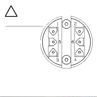
4.INSTALLATION
Terminal
Assignment
for Models 2111R,
2112R, 2113R
1 Sender in
2Battery +
3Ground
4 Sender low (optional: for use with two wire senders)
5 Output signal (upper)
6 Output signal (lower)
!
11
Page 13

Terminal Assignment for
Model 2114R
1 Not Connected **
2Battery +
3Ground
4 Not Connected**
5 Output signal (upper)
6 Output signal (lower)
Terminal Assignments for Models 2211R,
2212R, 2213R
1 Sender in
2Battery +
3Ground
4 Hourmeter enable*
5 Output signal (upper)
6 Output signal (lower)
!
12
Page 14

Terminal Assignments for
Model 2214R
1 Not connected***
2Battery +
3Ground
4 Hourmeter enable***
5 Output signal (upper)
6 Output signal (lower)
* Options terminal can be factory programmed to function as
hourmeter reset or sender low (for use with two wire senders)
**Options terminal-can be factory programmed to measure a
separate variable voltage supply.
***Options terminals-can be factory programmed to measure a
separate variable voltage supply. Hourmeter enable terminal
could be factory programmed as an hourmeter reset.
!
13
Page 15

5. TROUBLESHOOTING
The following checklist should help you to troubleshoot any problems with the instrument.Turning
the instrument off and then on again after about 10
seconds may solve the problem in the simplest cases.
Make sure to observe the safety instructions in Section 1.
Problem Possible Cause
No display Voltage on Battery + terminal insufficient
Display is not
accurate Check sender installation.Teflon tape, some
lubricants and anti-sieze compounds may
prevent proper grounding of single wire
senders.Check sender-to-gage wiring for
excessive resistance.
!
14
Page 16

6. MAINTENANCE
Curtis 2100R & 2200R Series Engine Gages are
not serviceable in the field. Units returned to the
factory within the warranty period will be replaced
without charge.
16
!
Page 17

Guarantee - These Curtis Instruments’ products are guaranteed against defects in workmanship and material for a period
of three years, or as defined in the individual product literature,
from date of shipment from our factory, when applied in a proper application within specified ratings.This guarantee is limited
to repair or replacement F.O.B. our factory.There is no further
warranty or implied representation, guarantee, promise or
agreement as to any Curtis Instruments product and/or component. Curtis Instruments, Inc., cannot assume responsibility or
accept invoices for unauthorized repairs to its products and/or
components, even though defective.In no case will Curtis
Instruments’ responsibility extend to products, components
or equipment not of its manufacture.Under no circumstances
shall Curtis Instruments, Inc., be liable for any special or
consequential damages or loss of profits or other damages.
Returned goods will not be accepted unless identified by a
Curtis Return Material Authorization (RMA).
All specifications are subject to change
without notice.
Page 18

CURTIS INSTRUMENTS, INC.
200 Kisco Avenue, Mt. Kisco, NY 10549
Tel. (914) 666-2971 • FAX (914) 666-2188
53018 REV A 10/97
 Loading...