

Page 1

Manual
Model 1244
MultiMode™ Electronic Motor Controller
Read Instructions Carefully!
Specications are subject to change without notice.
© 2013 Curtis Instruments, Inc. ® Curtis is a registered trademark of Curtis Instruments, Inc.
© The design and appearance of the products depicted herein are the copyright of Curtis Instruments, Inc. 16958 Rev E 10/2013
Curtis Instruments, Inc.
200 Kisco Avenue
Mt. Kisco, NY 10549
www.curtisinstruments.com
Page 2

Page 3

CONTENTS
1. OVERVIEW ...........................................................................................1
2. INSTALLATION AND WIRING .........................................................4
Mounting the Controller ..................................................................4
Connections: Low Current ..............................................................6
Connections: High Current .............................................................7
Wiring: Controller ........................................................................... 8
Wiring: rottle.............................................................................10
5kΩ–0, 2-wire resistive throttle (“Type 1”) ..............................11
0–5V, current source, 3-wire pot, and electronic
single-ended throttles (“Type 2”) .....................................12
0–5kΩ, 2-wire resistive throttle (“Type 3”) ..............................15
0–5V and 3-wire pot wigwag-style throttles (“Type 4”) ............15
CAN-Nodes throttle (“Type 5”) ..............................................16
Wiring: Fault Outputs ...................................................................16
Wiring: Contactor Drivers ............................................................. 16
Wiring: Pedal Switch .....................................................................19
Wiring: Hour Meter ......................................................................19
Wiring: CAN Bus Interface ...........................................................19
Wiring: Emergency Reverse ........................................................... 19
Contactor, Switches, and Other Hardware ......................................21
CONTENTS
3. PROGRAMMABLE PARAMETERS ..................................................23
Acceleration Parameters ..................................................................26
Acceleration Rate, M1–M4 ......................................................26
Braking Rate, M1–M4 ............................................................26
Deceleration Rate ....................................................................26
Quick Start .............................................................................. 26
Taper Rate ............................................................................... 27
Speed Parameters ............................................................................27
Maximum Speed, M1–M4 ......................................................27
Creep Speed, M1–M4 ............................................................. 27
Regen Speed ............................................................................27
rottle Parameters ......................................................................... 28
Control Mode..........................................................................28
rottle Type ........................................................................... 29
rottle Deadband ..................................................................30
rottle Max ...........................................................................32
rottle Map, M1–M4 ............................................................ 34
rottle Braking Percent, M1–M4 ...........................................36
Current Limit Parameters ...............................................................36
Drive Current Limit, M1–M4 .................................................36
Braking Current Limit, M1–M4 ..............................................36
Minimum Field Current Limit ................................................ 36
Maximum Field Current Limit ................................................ 37
Restraint .................................................................................. 37
Emergency Reverse Current Limit ...........................................38
Current Ratio .......................................................................... 38
Curtis 1244 Manual, Rev. E
iii
Page 4

CONTENTS
Field Control Parameters ................................................................38
Field Map Start ........................................................................ 38
Field Map ................................................................................ 39
Fault Parameters ..............................................................................41
High Pedal Disable (HPD) ...................................................... 41
HPD reshold ....................................................................... 42
Static Return to O (SRO) ...................................................... 42
Fault Code ............................................................................... 42
Output Driver Parameters ...............................................................43
Main Contactor Driver Interlock .............................................43
Main Contactor Dropout Delay ..............................................43
Main Coil Open Check ........................................................... 44
Main Contactor Weld Check ................................................... 44
Auxiliary Driver Dropout Delay ..............................................44
Auxiliary Coil Open Check .....................................................44
Reverse Signal Open Check .....................................................45
Electromagnetic Brake Delay ...................................................45
Electromagnetic Brake Open Check ........................................45
Contactor Holding Voltage ......................................................46
Contactor Pull-in Voltage ........................................................46
Other Parameters ............................................................................ 46
Battery Voltage ........................................................................46
Anti-Tiedown ..........................................................................47
Sequencing Delay .................................................................... 47
Pedal Interlock ......................................................................... 47
Emergency Reverse Enable .......................................................48
Emergency Reverse Check ....................................................... 48
Node Address ..........................................................................48
Precharge ................................................................................ 49
Load Compensation ................................................................ 49
4. OEMSPECIFIED, FACTORYSET PARAMETERS .........................50
MultiMode™ Enable ...................................................................... 50
Accessory Driver Enable ..................................................................50
CAN Bus Enable ............................................................................51
5. INSTALLATION CHECKOUT .........................................................52
6. VEHICLE PERFORMANCE ADJUSTMENT ..................................54
Major Tuning ..................................................................................54
Tuning the active throttle range ..............................................54
Tuning the controller to the motor .........................................57
Setting the unloaded vehicle top speed ....................................59
Equalizing loaded and unloaded vehicle speed ........................60
Fine Tuning ....................................................................................62
Response to increased throttle .................................................. 62
Response to reduced throttle .................................................... 63
Smoothness of direction transitions .........................................63
Ramp climbing ....................................................................... 65
Ramp restraint ........................................................................ 66
iv
Curtis 1244 Manual, Rev. E
Page 5

7. PROGRAMMER MENUS .................................................................67
Paraneters Menu .............................................................................67
Monitor Menu ................................................................................ 70
Diagnostics Menu ........................................................................... 71
Other Menus .................................................................................. 71
8. DIAGNOSTICS AND TROUBLESHOOTING................................72
Programmer Diagnostics ................................................................. 72
LED Diagnostics ............................................................................ 74
Fault Output Drivers ...................................................................... 75
9. MAINTENANCE ................................................................................76
Cleaning ........................................................................................ 76
Diagnostic History .........................................................................76
appendix a Glossary of Features and Functions
appendix b Programming Devices
appendix c Specifications, 1244 Controller
CONTENTS
Curtis 1244 Manual, Rev. E
v
Page 6

FIGURES / TABLES
. 1: Curtis 1244 electronic motor controller ...................................1
. 2: Mounting dimensions, Curtis 1244 controller ........................4
. 3: Standard wiring configuration ..................................................8
. 4: Wiring for 5kΩ–0 throttle (“Type 1”) .................................... 11
. 5: Wiring for wigwag throttle,
using the 5kΩ–0 throttle input (“Type 1”) ............................. 11
. 6: Wiring for 0–5V throttle (“Type 2”) ...................................... 12
. 7: Wiring for 3-wire potentiometer throttle (“Type 2”) .............. 13
. 8: Wiring for current source throttle (“Type 2”) ......................... 13
. 9: Wiring for Curtis ET-XXX electronic throttle (“Type 2”) ......14
. 10: Wiring for 0–5kΩ throttle (“Type 3”) ....................................15
. 11: Wiring for fault outputs .........................................................16
. 12: Wiring for main and auxiliary contactor coils when using
the interlock and dropout delay features .................................18
FIGURES
. 13: Wiring for emergency reverse
(applicable to walkie vehicles only) .........................................20
. 14: Eect of adjusting the neutral deadband parameter .........30, 31
. 15: Eect of adjusting the throttle max parameter .................32, 33
. 16: rottle maps for controller with maximum speed set
at 100% and creep speed set at 0 ...........................................34
. 17: rottle maps for controller with maximum speed set
at 80% and creep speed set at 10% .......................................35
. 18: Inuence of various parameters on controller output
response to throttle demand ..................................................35
. 19: Field current relative to armature current,
with field map parameter set at 50% and 20% ......................40
TABLES
1: Voltages at throttle wiper input ............................................ 10
2: Mode selection ..................................................................... 22
3: Programmable throttle types ................................................. 29
4: Fault categories .................................................................... 43
5: Troubleshooting chart .......................................................... 73
6: Status LED fault codes ........................................................ 74
7: Fault category codes ............................................................ 75
C-1: Specifications, 1244 controller ....................................... C-1
vi
Curtis 1244 Manual, Rev. E
Page 7
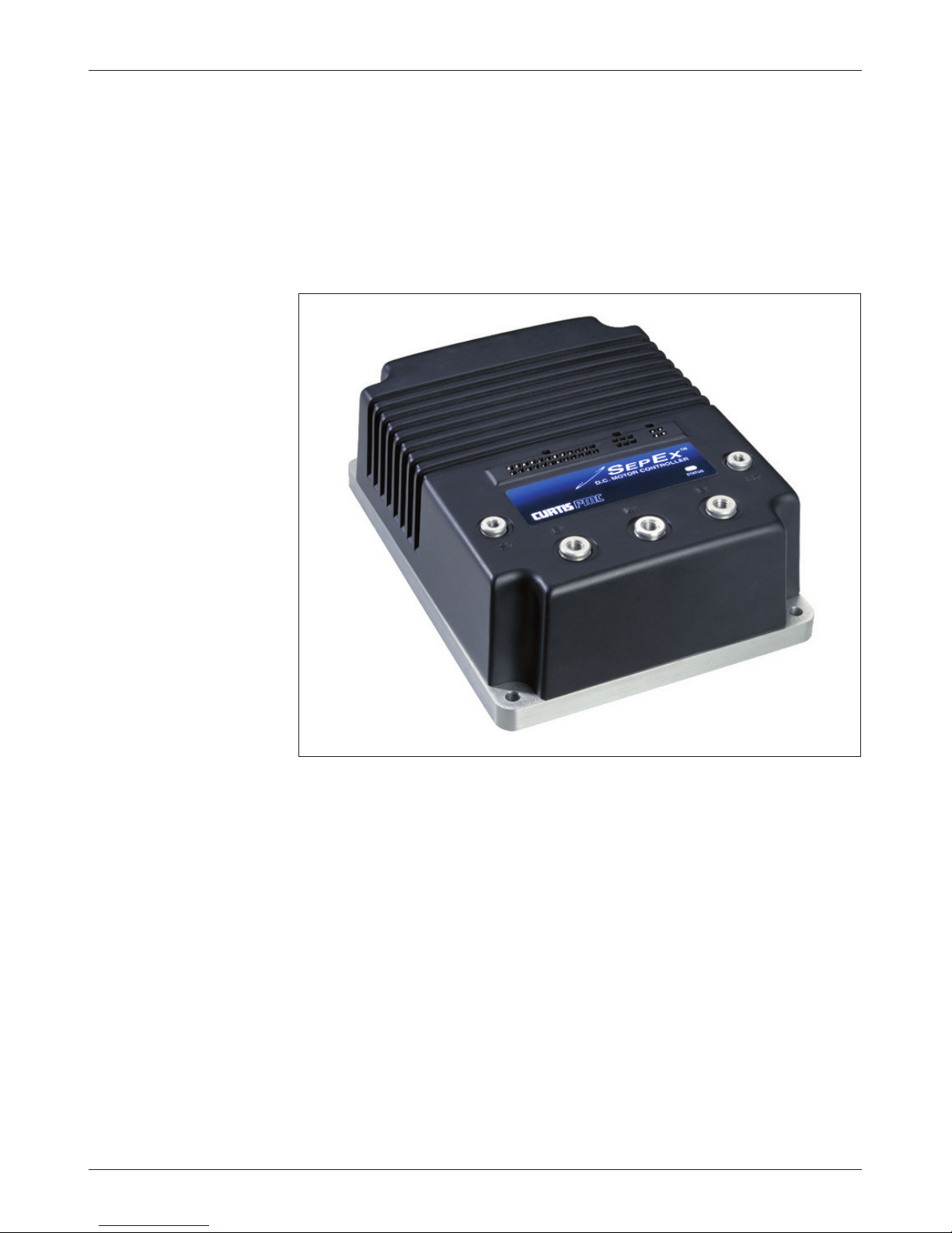
1
Fig. 1 Curtis 1244
MultiMode™ electronic
motor controller.
1 — OVERVIEW
OVERVIEW
Curtis 1244 MultiMode™ controllers are separately excited motor speed controllers designed for use in a variety of material handling vehicles. ese programmable controllers are simple to install, efficient, and cost eective. Typical
applications include low lifts, stackers, fork lifts, reach trucks, personnel carriers,
counterbalance trucks, order pickers, boom trucks, and other industrial vehicles.
control of motor speed and torque. A four quadrant, full-bridge field winding
control stage is combined with a two quadrant, half-bridge armature power stage
to provide solid state motor reversing and regenerative braking power without
additional relays or contactors. e 1244 controller can also be specified to be
compatible with CAN Bus communication systems.
held programmer or PC programming station. Use of the programmer provides
diagnostic and test capability as well as configuration exibility.
Curtis 1244 Manual, Rev. E
e 1244 MultiMode™ controller oers smooth, silent, cost eective
ese controllers are fully programmable by means of the optional hand-
1
Page 8

1 — OVERVIEW
Like all Curtis motor controllers, the 1244 oers superior operator control of
the vehicle’s motor drive speed. Features include:
✓ Full-bridge field and half-bridge armature power MOSFET design,
providing
•infinitelyvariableforward,reverse,drive,andbrakecontrol
• silenthighfrequencyoperation
• highefficiency
✓ Regenerative braking, providing longer operation on a single battery charge
and reducing motor brush wear and motor heating
✓ Programmability through the 1313 handheld programmer and 1314 PC
Programming Station
✓ Complete diagnostics through the programmer and the internal Status LED
✓ Two fault outputs provide diagnostics to remotely mounted displays
✓ Continuous armature current control, reducing arcing and brush wear
✓ Automatic braking when throttle is reduced from either direction; this
provides a compression braking feel and enhances safety by automatically
initiating braking in an operator hands o condition
✓ Deceleration Rate, Load Compensation, and Restraint features prevent
downhill runaway conditions; speed is controlled to within approximately
20% of level surface value
✓ MultiMode™ allows four user-selectable vehicle operating personalities
✓ Programmable to match individual separately excited motor characteristics
✓ Meets or exceeds EEC fault detect requirements
✓ Vehicle top speed is controlled and limited in each mode
✓ Linear temperature and undervoltage cutback on motor currents; no sudden
loss of power under any thermal conditions
✓ High pedal disable (HPD) and static return to o (SRO) interlocks prevent
vehicle runaway at startup
✓ Creep speed adjustable from 0% to 25% in each mode
✓ Continuous diagnostics during operation, with microprocessor power-on
self-test
✓ Internal and external watchdog circuits ensure proper software operation
✓ Programmable coil drivers provide adjustable contactor pull-in and holding
voltages
✓ Hour-meter enable output is active whenever the controller is providing
motor current
✓ Optional Electromagnetic Brake Driver provides automatic control of an
✓ Optional Reverse Signal Driver provides a low signal any time the vehicle
2
electromagnetic brake or other similar function
is driving or braking in reverse
Curtis 1244 Manual, Rev. E
Page 9

1 — OVERVIEW
✓ Optional Auxiliary Driver provides a low signal to power an auxiliary
contactor or other similar function
✓ Driver outputs are short circuit protected and provide built-in coil spike
protection
✓ Controller is programmable to provide throttle control of motor speed,
applied motor voltage, or motor torque
✓ Can be configured for CAN Bus compatibility.
Familiarity with your Curtis controller will help you install and operate it
properly. We encourage you to read this manual carefully. If you have questions,
please contact the Curtis office nearest you.
Curtis 1244 Manual, Rev. E
3
Page 10
2 — INSTALLATION & WIRING: Controller
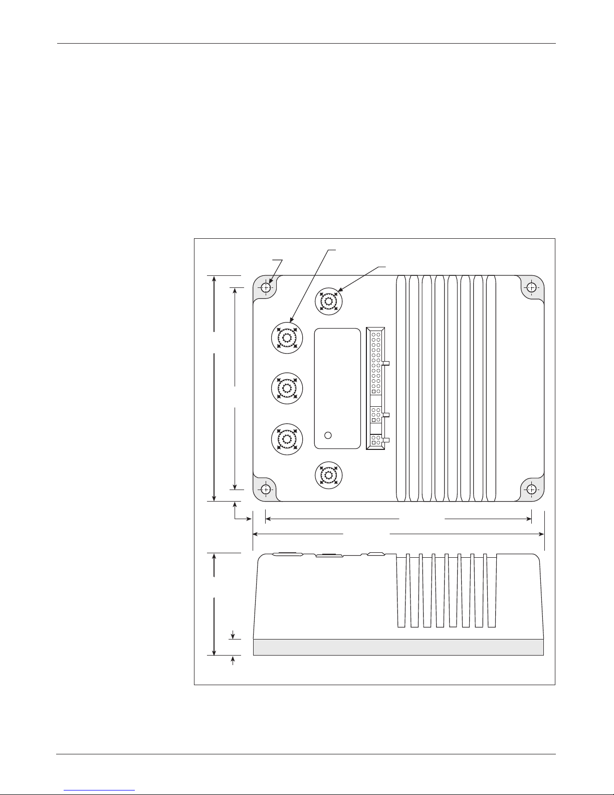
MOUNTING THE CONTROLLER
2
e outline and mounting hole dimensions for the 1244 controller are shown
in Figure 2.
ratings for environmental protection against dust and water. However, the lo-
cation should be carefully chosen to keep the controller as clean and dry
as possible.When selecting the mounting position, be sure to also take into
consideration (1) that access is needed at the top of the controller to plug the
INSTALLATION AND WIRING
e controller can be oriented in any position, and meets the IP64/IP67
Fig. 2 Mounting
dimensions, Curtis
1244 controller.
7.1 (0.28) dia.,
178
(7.00)
159
(6.25)
9.5
(0.375)
4 plcs
M8 thread, 3 plcs
STATUS
LED
229 (9.00)
M6 thread, 2 plcs
210 (8.25)
(3.19)
Dimensions in millimeters (and inches)
4
81
12.7
(0.50)
Curtis 1244 Manual, Rev. E
Page 11

2 — INSTALLATION & WIRING: Controller
programmer into its connector, and (2) that the built-in Status LED is visible
only through the view port in the label on top of the controller.
To ensure full rated power, the controller should be fastened to a clean,
at metal surface with four 6 mm (1/4") diameter screws, using the holes provided. Although not usually necessary, a thermal joint compound can be used to
improve heat conduction from the controller heatsink to the mounting surface.
CAUTION
☞
Working on electric vehicles is potentially dangerous. You should protect yourself against runaways, high current arcs, and outgassing from lead
acid batteries:
RUNAWAYS — Some conditions could cause the vehicle to run out of control.
Disconnect the motor or jack up the vehicle and get the drive wheels o
the ground before attempting any work on the motor control circuitry.
: If the wrong throttle type is selected with the programming device,
the vehicle may suddenly begin to move.
HIGH CURRENT ARCS — Electric vehicle batteries can supply very high power,
and arcs can occur if they are short circuited. Always open the battery
circuit before working on the motor control circuit. Wear safety glasses,
and use properly insulated tools to prevent shorts.
LEAD ACID BATTERIES — Charging or discharging generates hydrogen gas,
which can build up in and around the batteries. Follow the battery manufacturer’s safety recommendations. Wear safety glasses.
Curtis 1244 Manual, Rev. E
5
Page 12

24 23 22 21 20 19 18 17 16 15 14 13
12 11 10 9 8 7 6 5 4 3 2 1
2 — INSTALLATION & WIRING:
Controller
CONNECTIONS
Low Current Connections
ree low current connectors are built into the 1244 controller. ey are located
in a row on the top of the controller:
24-pin 6-pin 4-pin
e 24-pin connector provides the logic control connections. e mating
connector is a 24-pin Molex Mini-Fit Jr. connector part number 39-01-2245
using type 5556 terminals.
Pin 1 keyswitch input (KSI)
Pin 2 interlock input
Pin 3 Mode Select 1 input
Pin 4 Mode Select 2 input
Pin 5 Fault 1 output
Pin 6 Fault 2 output
Pin 7 emergency reverse input
Pin 8 pedal switch input
Pin 9 coil return input
Pin 10 forward input
Pin 11 reverse input
Pin 12 hour meter enable output
Pin 13 throttle: 3-wire pot high
Pin 14 throttle: pot low
Pin 15 throttle: 3-wire pot wiper or 0–5V
Pin 16 throttle: 2-wire 5kΩ–0 or 0–5kΩ input
Pin 17 main contactor driver output
Pin 18 auxiliary contactor driver output
Pin 19 reverse signal driver output
Pin 20 electromagnetic brake driver output
Pin 21 (not used)
Pin 22 emergency reverse check output
Pin 23 (not used)
Pin 24 (not used)
6
Curtis 1244 Manual, Rev. E
Page 13
B- B+M-
456
123
2 — INSTALLATION & WIRING: Controller
A 6-pin low power Molex connector is provided for the CAN Bus interface.
However, the CAN Bus option must be specified for this interface to be active.
e mating connector is a Molex Mini-Fit Jr. p/n 39-01-2065 using type 5556
terminals.
Pin 1 +15V supply (limited)
Pin 2 ground return (B-)
Pin 3 CAN H I/O line
Pin 4 L termination
Pin 5 H termination
Pin 6 CAN L I/O line
e +15V supply should only be used with the CAN system or speed sensor
and not to power any other external systems.
e L and H terminations provide a 120Ω termination impedance for
the CAN H I/O and CAN L I/O inputs if necessary. Refer to the Curtis CAN
Protocol Document to determine the proper termination for a given application.
CABLE-FREE ZONES
F1
A 4-pin low power connector is provided for the handheld 1313 programmer
or 1314 PC programming station. A complete programmer kit, including the
appropriate connecting cable, can be ordered from Curtis.
If a programmer is already available but has an incompatible cable, the
1244 mating cable can be ordered as a separate part: Curtis p/n 16185.
High Current Connections
Five tin-plated solid aluminum bus bars are provided for the high current connections to the battery
and
F2). ese bus bars incorporate threaded mounting studs designed to accept
mounting bolts. e
(B+ and B-), the motor armature (M-), and the motor field (F1
B+, B-, and M- bus bars are threaded to accept M8 bolts to
a depth of 3/4". e F1 and F2 bus bars are threaded to accept M6
bolts to a depth of 5/8". is simplifies the assembly
STATUS
LED
and reduces the mounting hardware necessary for the
power connections. e tightening torque applied to
F2
the bolts should not exceed 16.3 N·m (12 ft-lbs) for
the M6 bolts or 20 N·m (15 ft-lbs) for the M8 bolts.
Exceeding these specifications could damage the bus
bars’ internal threads, resulting in loose connections.
CAUTION
☞
Power cables must not be routed over the indicated areas. Otherwise they
may interfere with the proper operation of sensitive electromagnetic components located underneath.
Curtis 1244 Manual, Rev. E
7
Page 14
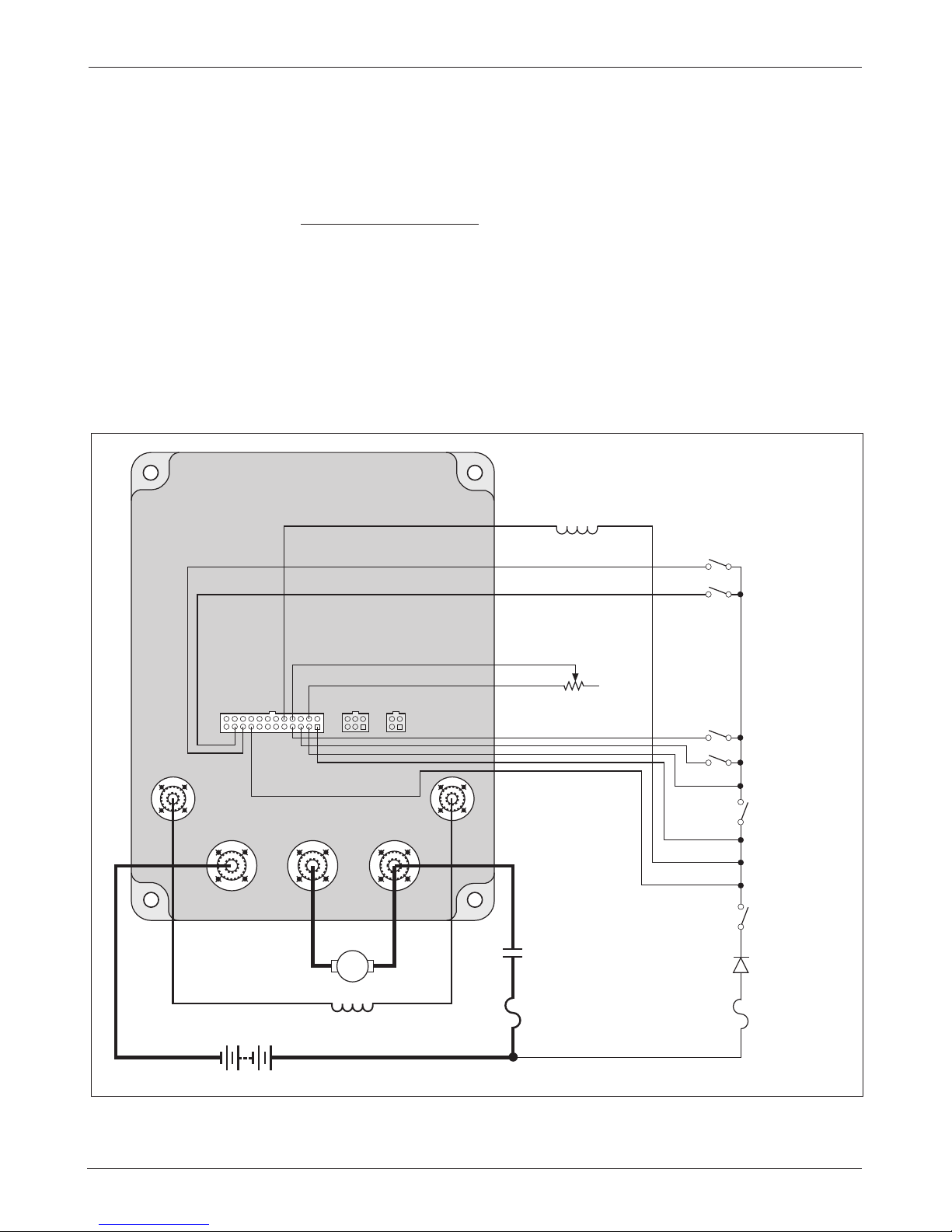
2 — INSTALLATION & WIRING: Controller
B- B+M-
F2F1
INTERLOCK
5 kΩ–0 THROTTLE
(TYPICAL)
FORWARD
MAIN
CONTACTOR
COIL
POLARITY
PROTECTION
DIODE
REVERSE
MODE SELECT 2
MODE SELECT 1
B+
B-
KEYSWITCH
POWER
FUSE
A
MAIN
CONTACTOR
A2 A1
F1 F2
CONTROL
FUSE
WIRING: Standard Conguration
Figure 3 shows the typical wiring configuration for most applications. e
interlock switch is typically a seat switch, tiller switch, or foot switch.
Standard Power Wiring
Motor armature winding is straightforward, with the armature’s A1 connection
going to the controller’s B+ bus bar and the armature’s A2 connection going
to the controller’s M- bus bar.
vious. e direction of vehicle travel with the forward direction selected will
depend on how the
terminals and how the motor shaft is connected to the drive wheels through
the vehicle’s drive train.
e motor’s field connections (
F1 and F2 connections are made to the controller’s two field
F1 and F2) to the controller are less ob-
Fig. 3 Standard wiring configuration, Curtis 1244 controller.
8
Curtis 1244 Manual, Rev. E
Page 15

2 — INSTALLATION & WIRING: Controller
Standard Control Wiring
Wiring for the input switches and contactors is shown in Figure 3; the connector
is shown in more detail below.
24-pin detail (see Fig. 3):
EMERGENCY
REVERSE
CHECK
(factory option)
ELECTRO-
MAGNETIC
BRAKE
DRIVER
REVERSE
SIGNAL
DRIVER
AUX
CONTACTOR
DRIVER
MAIN
CONTACTOR
DRIVER
2-WIRE
POT
(5 kΩ)
POT
WIPER
POT
LOW
POT
HIGH
24 23 22 21 20 19 18 17 16 15 14 13
12 11 10 9 8 7 6 5 4 3 2 1
HOUR
METER
REVERSE
FORWARD
COIL
RETURN
PEDAL
SWITCH
EMERGENCY
REVERSE
(walkies only)
FAULT
2
FAULT
1
MODE
SELECT
2
MODE
SELECT
1
INTERLOCK
KEYSWITCH
INPUT (KSI)
e main contactor coil must be wired directly to the controller as shown in
Figure 3. e controller can be programmed to check for welded or missing
main contactor faults and uses the main contactor coil driver output to remove
power from the controller and motor in the event of various other faults. If the
main contactor coil is not wired to Pin 17, the controller will not be able
to open the main contactor in serious fault conditions and the system will
therefore not meet EEC safety requirements.
Curtis 1244 Manual, Rev. E
9
Page 16

2 — INSTALLATION & WIRING: Throttle
WIRING: Throttle
Various throttles can be used with the 1244 controller. ey are categorized
as one of five types in the programming menu of the handheld programmer.
Type 1: two-wire 5kΩ–0 throttles
Type 2: 0–5V throttles, current source throttles, three-wire potentiometer
throttles, and electronic throttles—wired for single-ended operation
Type 3: two-wire 0–5kΩ throttles
Type 4: 0–5V and three-wire potentiometer throttles—wired for wigwag-style operation
Type 5: CAN-Nodes throttles
e operating specifications for these throttle types are summarized in Table 1.
Table 1 THROTTLE WIPER INPUT: THRESHOLD VALUES
MINIMUM THROTTLE HPD THROTTLE MAXIMUM
THROTTLE THROTTLE DEADBAND (25% throttle MAX THROTTLE
TYPE PARAMETER FAULT (0% throttle) active range) (100% modulation) FAULT
1 Wiper Voltage 0.1 V 3.3 V 1.0 V 0.2 V 4.4 V
Wiper Resistance — 5.0 kΩ 3.8 kΩ 0 kΩ 7.5 kΩ
2 Wiper Voltage (none) 0.2 V 1.4 V 5.0 V 5.5 V
Wiper Resistance — — — — —
3 Wiper Voltage 0.1 V 0.2 V 1.0 V 3.3 V 4.4 V
Wiper Resistance — 0 kΩ 1.3 kΩ 5.0 kΩ 7.5 kΩ
4 Wiper Voltage 0.5 V 2.5 V (fwd)* 3.1 V (fwd) 4.4 V (fwd) 4.5 V
2.5 V (rev)* 1.9 V (rev) 0.6 V (rev)
Wiper Resistance 0.5 kΩ 2.5 kΩ (fwd)* 3.1 kΩ (fwd) 4.4 kΩ (fwd) 4.5 kΩ
2.5 kΩ (rev)* 1.9 kΩ (rev) 0.6 kΩ (rev)
5 Wiper Voltage N/A N/A N/A N/A N/A
Wiper Resistance N/A N/A N/A N/A N/A
Notes: The Upper and Lower Deadbands are valid for nominal 5kΩ potentiometers or 5V sources with the
default Throttle Deadband and Throttle Max parameter settings of 0% and 100% respectively. These
values will change with variations in the Throttle Deadband and Throttle Max parameter settings—see
Section 3, pages 30 and 32.
The HPD threshold is a percentage of the active throttle range, which is dependent on the pro-
grammed Throttle Deadband and Throttle Max settings. The default HPD Threshold is 25%; the
programmable range is 0–25%.
* With 0% Throttle Deadband, there is no neutral point on a Type 4 throttle. It is recommended that
an 8% minimum deadband be used with Type 4 throttles.
All throttle fault protection is accomplished by monitoring the wiper input.
is provides throttle fault protection that meets all EEC requirements. us,
no additional fault protection is required on any throttle type used with the
1244 controller.
10
Curtis 1244 Manual, Rev. E
Page 17
2 — INSTALLATION & WIRING: Throttle
Pin 14
Pot Low
Wiring for various throttles is described below. : In the text, throttles
are identified by their nominal range and not by their actual operating range.
If the throttle you are planning to use is not covered, contact the Curtis
office nearest you.
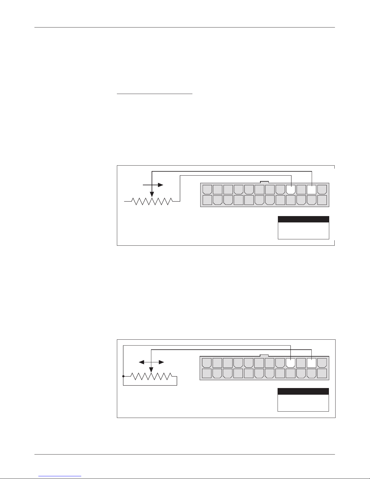
5kΩ–0 Throttle (“Type 1”)
e 5kΩ–0 throttle (called a “Type 1” throttle in the programming menu of
the handheld programmer) is a 2-wire resistive throttle that connects between
the 2-Wire Pot and Pot Low pins (Pins 16 and 14), as shown in Figure 4. It
doesn’t matter which wire goes on which pin. For Type 1 throttles, zero speed
corresponds to a nominal 5 kΩ measured between the two pins and full speed
corresponds to 0Ω. (: is wiring is also shown in the standard wiring
diagram, Figure 3.)
Fig. 4 Wiring for 5k
Ω
–0
throttle (“Type 1”).
Fig. 5 Wiring for 20k
Ω
potentiometer used as part
of a wigwag-style throttle
(“Type 1”).
FASTER
14 1315161718192021222324
12 11 10 9 8 7 6 5 4 3 2 1
5kΩ–0
PIN KEY
Pin 16
Pin 14
2-Wire Pot
Pot Low
In addition to accommodating the basic 5kΩ–0 throttle, the Type 1 throttle
can also be used to implement a wigwag-style throttle. Using a 20kΩ pot wired
as shown in Figure 5, the pot wiper can be set such that the controller has 5 kΩ
between Pins 16 and 14 when the throttle is in the neutral position. e throttle
mechanism can then be designed such that rotating it either forward or back
decreases the resistance between Pins 16 and 14, which increases the controller
output. e throttle mechanism must provide signals to the controller’s forward
and reverse inputs independent of the throttle pot resistance. e controller
will not sense direction from the pot resistance with rottle Type 1. For true
FASTERFASTER
12 11 10 9 8 7 6 5 4 3 2 1
14 1315161718192021222324
Curtis 1244 Manual, Rev. E
20 kΩ
Pin 16
PIN KEY
2-Wire Pot
11
Page 18
14 1315161718192021222324
12 11 10 9 8 7 6 5 4 3 2 1
14 1315161718192021222324
12 11 10 9 8 7 6 5 4 3 2 1
+
-
+
B-
Pin 15
0–5V Input
PIN KEY
Pin 15
Pin 14
0–5V Input
Pot Low
PIN KEY
SENSOR GROUND
SENSOR OUTPUT (0–5V)
SENSOR
2 — INSTALLATION & WIRING: Throttle
wigwag-style control—without the necessity of providing independent forward
and reverse input signals—see rottle Type 4.
controller’s 4.4 V upper fault limit will be exceeded and the controller output
will be disabled. is provides broken wire protection, and also serves as an
indication that the potentiometer’s nominal value has increased and the pot
needs to be replaced.
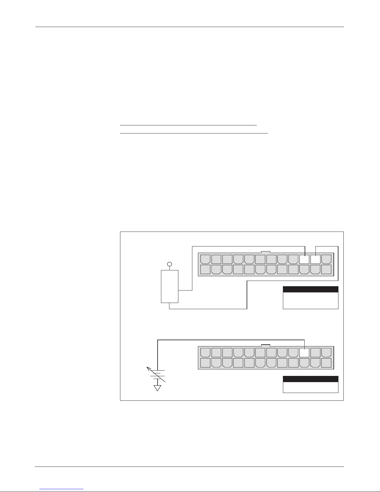
0–5V, 3-Wire Potentiometer, Current Source,
and Electronic Single-Ended Throttles (“Type 2”)
With these throttles (“Type 2” in the programming menu) the controller looks
for a voltage signal at the wiper input (Pin 15). Zero speed will correspond to
0V and full speed to 5 V. A 3-wire pot, voltage source, voltage sensor, or current
source can be used with this throttle type. e wiring for each is slightly dierent.
0–5V rottle
Two ways of wiring the 0–5V throttle are shown in Figure 6. e active range
for this throttle is from 0.2V (at 0% rottle Deadband) to 5.0 V (at 100%
rottle Max), measured relative to B-.
If the total resistance between Pins 14 and 16 is greater than 7.5 kΩ, the
Fig. 6 Wiring for
0–5V throttles (“Type 2”).
(a) Sensor-referenced
0–5V throttle
(b) Ground-referenced
0–5V throttle
12
Curtis 1244 Manual, Rev. E
Page 19
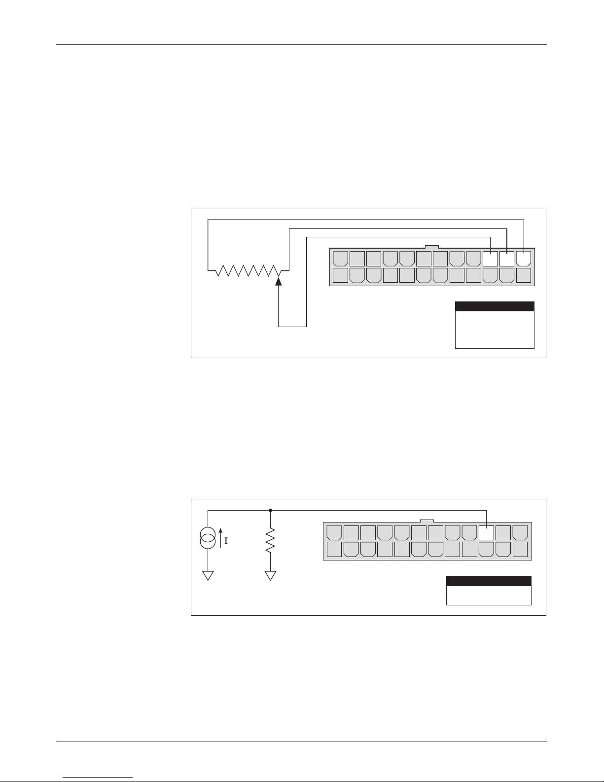
Fig. 7 Wiring for 3-wire
14 1315161718192021222324
12 11 10 9 8 7 6 5 4 3 2 1
R
throttle
B-B-
source
Pin 15
0–5V Input
PIN KEY
I
potentiometer throttle
(“Type 2”).
2 — INSTALLATION & WIRING: Throttle
3-Wire Potentiometer (1kΩ–10kΩ) rottle
e 3-wire potentiometer is used in its voltage divider mode, with the voltage
source and return being provided by the 1244 controller. Pot High (Pin 13)
provides a current limited 5V source to the pot, and Pot Low (Pin 14) provides
the return path. e pot wiper is then connected to the Wiper Input (Pin15).
If a 3-wire pot is used in the application, the controller will provide full throttle
fault protection in accordance with EEC requirements. Potentiometers with total
resistance values between 1kΩ and 10kΩ can be used with rottle Type 2.
Wiring is shown in Figure 7.
Fig. 8 Wiring for current
source throttle (“Type 2”).
1kΩ–10kΩ
OFFON
12 11 10 9 8 7 6 5 4 3 2 1
Pin 15
Pin 14
Pin 13
14 1315161718192021222324
PIN KEY
Pot Wiper
Pot Low
Pot High
Current Sources As rottles
A current source can also be used as a throttle input, as shown in Figure 8. A
resistor, R
, must be used to convert the current source value to a voltage.
throttle
e resistor should be sized to provide a 0–5V signal variation over the full
current range.
Curtis 1244 Manual, Rev. E
13
Page 20
2 — INSTALLATION & WIRING: Throttle
14 1315161718192021222324
12 11 10 9 8 7 6 5 4 3 2 1
GREEN
ORANGE
BLACK
BLACK/WHITE
WHITE
WHT/BRN
B+
KEYSWITCH
connector
WHT/
GRN
Pin 15
Pin 11
Pin 10
Pin 1
0–5V Input
Reverse
Forward
KSI Input
PIN KEY
B-
ET-XXX
B-
Curtis ET-XXX Electronic rottle
e Curtis ET-XXX provides a 0–5V throttle and forward/reverse inputs for
the 1244 controller. Wiring for the ET-XXX is shown in Figure 9.
Fig. 9 Wiring for Curtis
ET-XXX electronic throttle
(“Type 2”).
throttle control. Alternatively, a complete control head assembly is available
from Curtis. is control head assembly—the CH series—combines the ETXXX throttle with a variety of standard control head switch functions for use
in walkie and lift truck applications.
14
e ET-XXX can be integrated into a control head to provide wigwag-style
Curtis 1244 Manual, Rev. E
Page 21
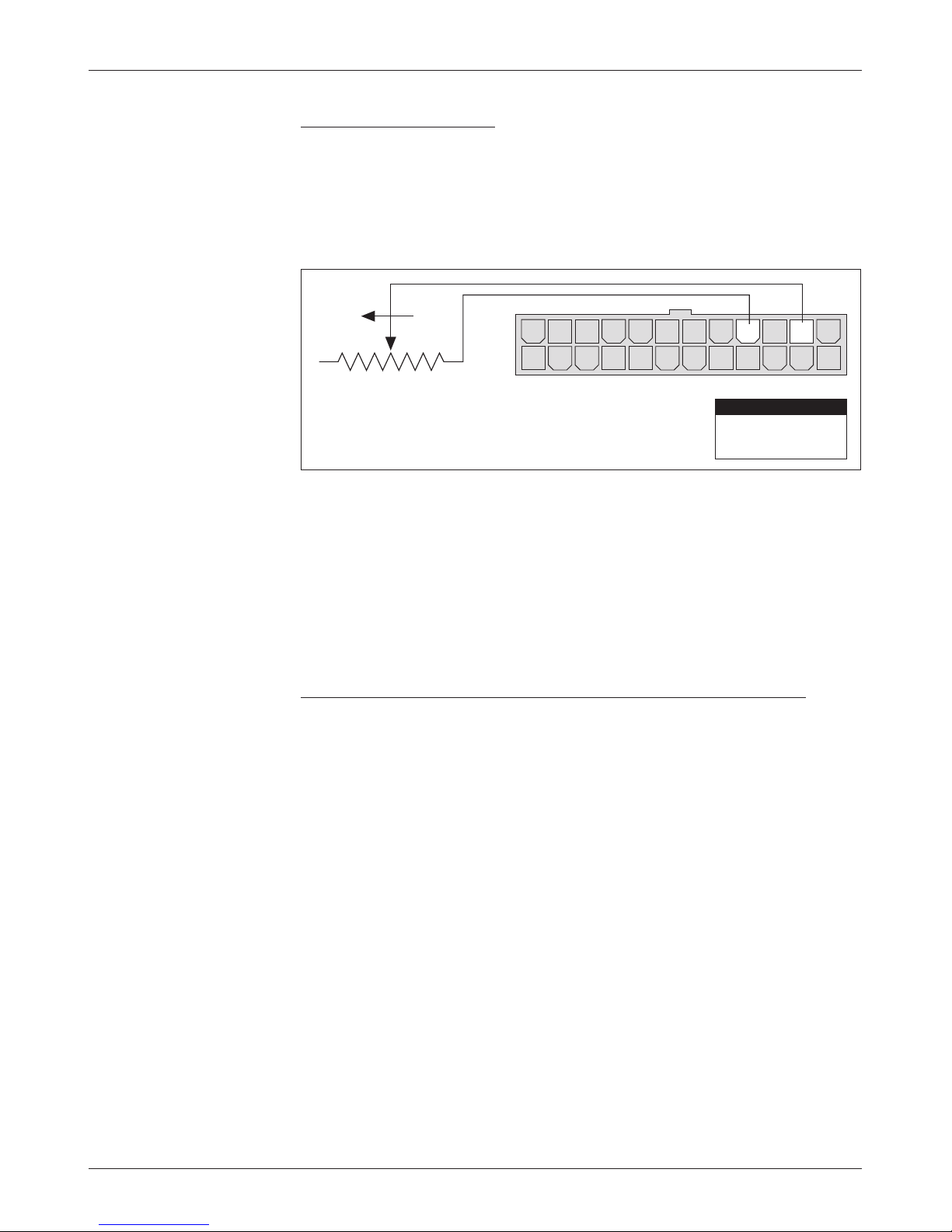
Fig. 10 Wiring
for 0–5k
Ω
throttle
(“Type 3”).
2 — INSTALLATION & WIRING: Throttle
0–5kΩ Throttle (“Type 3”)
e 0–5kΩ throttle (“Type 3” in the programming menu) is a 2-wire resistive
throttle that connects between the 2-Wire Pot and Pot Low pins (Pins 16 and 14)
as shown in Figure 10. Zero speed corresponds to 0Ω measured between the two
pins and full speed corresponds to 5 kΩ. is throttle type is not appropriate
for use in wigwag-style applications.
FASTER
14 1315161718192021222324
12 11 10 9 8 7 6 5 4 3 2 1
0–5kΩ
PIN KEY
Pin 16
Pin 14
2-Wire Pot
Pot Low
If the total resistance between Pins 14 and 16 is greater than 7.5 kΩ, the
controller’s 4.4 V upper fault limit will be exceeded and the controller output
will be disabled. is provides broken wire protection, and also serves as an
indication that the potentiometer’s nominal value has increased and the pot
needs to be replaced.
0–5V and 3-Wire Potentiometer Wigwag-Style Throttles (“Type 4”)
With these throttles (“Type 4” in the programming menu) the throttle can be
used in true wigwag style. Any potentiometer value between 1 kΩ and 10 kΩ
is supported. If a 5kΩ potentiometer is used, the neutral point will be with the
wiper at 2.5 kΩ (measured between the Pot Wiper and Pot Low pins [Pins 15
and 14]). e controller will provide increasing speed in the forward direction
as the wiper is moved toward Pot High, with maximum forward speed reached
at 4.5 kΩ. e controller will provide increasing speed in the reverse direction
as the wiper is moved toward Pot Low, with maximum reverse speed reached
at 0.5 kΩ.
A 0–5V voltage source can also be used as the wiper input (see Figure6).
However, the minimum and maximum wiper voltage must not exceed the 0.5V
and 4.5V fault limits.
With a Type 4 throttle, no direction signals to the controllers’ forward and
reverse inputs are required. Direction is determined by the wiper input value.
e throttle interface to the controller is similar to that for Type 2 throttles.
Curtis 1244 Manual, Rev. E
15
Page 22
2 — INSTALLATION & WIRING: Fault Outputs and Contactor Drivers
CAN-Nodes Throttle (“Type 5”)
e “Type 5” throttle option is designed for use with CAN-based control
systems. No connections are required to the throttle input pins (Pins 13–16)
or direction pins (Pins 10 and 11), because all communications are handled
through the 6-pin CAN-Nodes interface connector. Details on how to combine
a given throttle with the CAN-Nodes system are provided in the Curtis CAN
Protocol Document. Fault detection for Type 5 throttles is handled by the
CAN CRC (Cyclic Redundancy Check) function, which is part of each node
in the CAN Bus architecture.
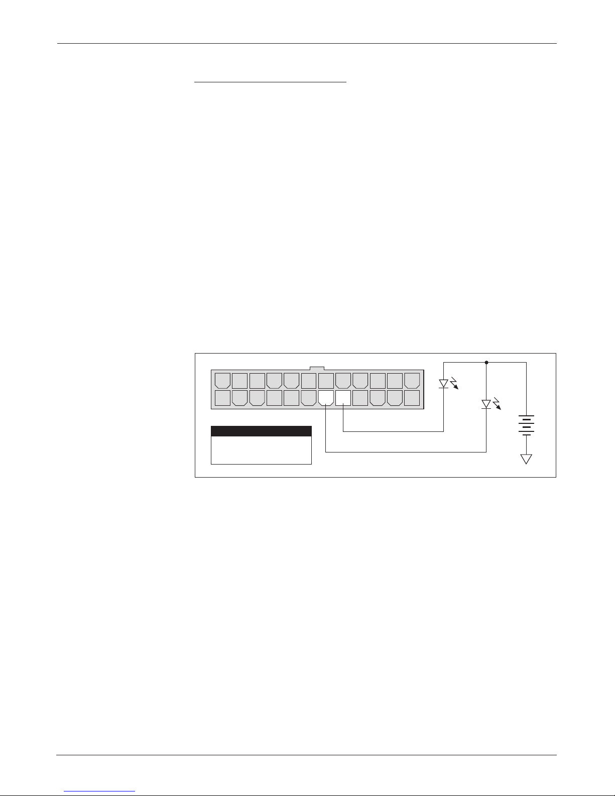
WIRING: Fault Outputs
e 1244 controller has two fault output drivers, at Pin 5 and Pin 6, which
can be used to provide diagnostic information either to a display panel on the
vehicle or to a remote location. ese outputs are rated at 10mA maximum
current at the nominal battery pack voltage. For information on programming
these outputs, see Section 3: Programmable Parameters.
Wiring for the Fault 1 and Fault 2 outputs is shown in Figure 11.
Fig. 11 Wiring for fault
outputs.
14 1315161718192021222324
12 11 10 9 8 7 6 5 4 3 2 1
+
Fault 1
Fault 2
-
B-
Pin 6
Pin 5
PIN KEY
Fault 2 Output
Fault 1 Output
WIRING: Contactor Drivers
e 1244 controller provides contactor coil drivers (at Pins 17–20) for the
main contactor, auxiliary contactor, reverse signal, and electromagnetic brake
functions. ese four outputs are low side drivers, designed to energize contactor
coils. e auxiliary, reverse signal, and electromagnetic brake drivers are optional
functions. ey are available only if the Accessory Driver option is specified—see
Section 4, page 50.
It is not necessary to specify the contactors’ coil voltage at the nominal
battery pack voltage as long as the Contactor Pull-In Voltage and Contactor
Holding Voltage parameters are programmed to accommodate the coils’ voltage rating. However, all coil voltage ratings should be the same, since only one
value of pull-in and holding voltage can be specified for all four of the drivers.
e driver outputs are rated at 2 amps and overcurrent protected at
3amps. e controller can be programmed to check for missing coil faults.
16
Curtis 1244 Manual, Rev. E
Page 23

2 — INSTALLATION & WIRING: Contactor Drivers
ese checks can be disabled using a programmer—see Section 3, pages 44 and
45. A coil suppression diode is provided internally to protect the drivers from
inductive spikes generated at turn-o. To take advantage of the controller’s
internal coil suppression diode, Pin 9 must be wired such that the return path
to the contactor drivers cannot be opened by any switches or contactors.
e driver loads are not limited to contactor coils. Any load can be connected to a Pin 17–20 driver as long as it does not exceed the driver’s 2 amp
current rating.
For information on programming the various contactor-related parameters,
see Section 3: Programmable Parameters.
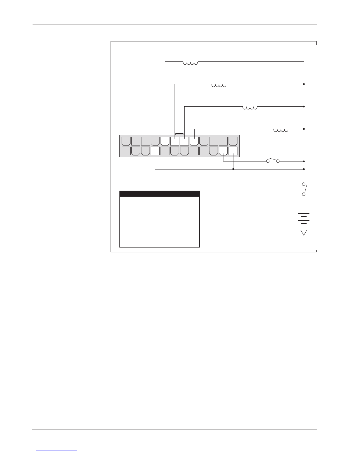
Main Contactor Driver
In the standard configuration, the main contactor driver (Pin 17) pulls low
when the keyswitch input is enabled; this wiring is shown in the standard wiring
diagram (Figure 3, page 8).
Alternatively, the main contactor driver can be programmed not to pull
low until the interlock input as well as the keyswitch input is enabled. To do
this, the Main Contactor Driver Interlock parameter must be set to “On.” If
the Main Contactor Driver Interlock parameter is On, the Main Contactor
Dropout Delay parameter can be set to allow the main contactor to remain
engaged for up to 40 seconds after the interlock signal has been disabled. If the
interlock and delay functions are used, the main contactor and the coil return
(Pin 9) must both be wired to KSI. is alternative wiring is shown in Figure 12.
Auxiliary Contactor Driver
Like the main contactor driver, the auxiliary contactor driver (Pin 18) pulls
low when the interlock input is enabled. e output will be pulse-width-modulated at the coil holding voltage along with the main, reverse signal, and
electromagnetic brake contactor drivers, if the Holding Voltage parameter is
set to less than 100%.
If desired, the Auxiliary Contactor Dropout Delay parameter can be set
to allow the auxiliary contactor to remain engaged for up to 40 seconds after
the interlock signal has been disabled. If the delay function is used, the auxiliary
contactor and the coil return (Pin 9) must both be wired to KSI rather than
the interlock input. is alternative wiring is shown in Figure 12.
Reverse Signal Driver
e reverse signal driver (Pin 19) pulls low when the vehicle is moving in the
reverse direction, either in drive or in braking mode. is driver is designed
to drive a reverse signal beeper or warning lamp that operates when one input
is pulled low. e output will be pulse-width-modulated at the coil holding
voltage along with the main, auxiliary, and electromagnetic brake contactor
drivers, if the holding voltage parameter is set to less than 100%.
Curtis 1244 Manual, Rev. E
17
Page 24
2 — INSTALLATION & WIRING: Contactor Drivers
14 1315161718192021222324
12 11 10 9 8 7 6 5 4 3 2 1
Pin 20
Pin 19
Pin 18
Pin 17
Pin 9
Pin 2
Pin 1
Electromagnetic Brake
Reverse Signal
Auxiliary Contactor
Main Contactor
Coil Return
Interlock Input
KSI Input
PIN KEY
MAIN
CONTACTOR
COIL
KEYSWITCH
+
ELECTROMAGNETIC BRAKE
CONTACTOR
COIL
INTERLOCK
AUXILIARY
CONTACTOR
COIL
REVERSE SIGNAL
CONTACTOR
COIL
B-
Fig. 12 Wiring for main,
auxiliary, reverse signal,
and electromagnetic brake
contactor coils, using the
interlock and dropout delay
functions.
Electromagnetic Brake Driver
e electromagnetic brake driver (Pin 20) pulls low when the controller receives
a throttle request or detects that the vehicle is still in braking mode. If desired,
the Brake Delay parameter can be set to allow the brake to remain disengaged
for up to 5 seconds after braking to neutral has been completed. If the delay
function is used, the brake driver and the coil return (Pin 9) must both be
wired to KSI rather than the interlock input. is alternative wiring is shown
in Figure 12.
time begins when the throttle is returned to neutral and the PWM output decelerates to zero. e output will be pulse-width-modulated at the coil holding
voltage along with the main, auxiliary, and reverse signal contactor drivers, if
the holding voltage parameter is set to less than 100%.
18
If the rottle Braking parameter has been set to zero, the brake delay
Curtis 1244 Manual, Rev. E
Page 25
2 — INSTALLATION & WIRING: Misc. Features
14 1315161718192021222324
12 11 10 9 8 7 6 5 4 3 2 1
Pin 22
Pin 7
Emergency Reverse Check
Emergency Reverse
PIN KEY
+
EMERGENCY
REVERSE
emergency reverse wiring check (optional)
B-
WIRING: Pedal Switch
When the Pedal Switch option is enabled, controller output is possible only when
the pedal input (Pin 8) is pulled to B+. is feature allows a switch connected to
the throttle mechanism to guarantee zero controller output when the operator
releases the throttle. is adds a safety feature to protect against throttle failures
that cause controller output when the throttle is in neutral.
Alternatively, the pedal input can be wired into the brake pedal circuit to
automatically force zero controller output when the brake pedal is depressed,
regardless of throttle request.
WIRING: Hour Meter
e hour meter output (Pin 12) pulls to B+ to enable an hour meter whenever
current is owing in the motor. is allows accurate accumulation of vehicle
operating hours. e output is current limited to 20 mA, and is compatible with
Curtis 700 and 800 series hour meters. For wiring, consult the documentation
supplied with the hour meter.
Fig. 13 Wiring for emer-
gency reverse (applicable to
walkie vehicles only).
WIRING: CAN Bus Interface
Refer to the Curtis CAN Protocol Document for information about the CAN
Bus interface.
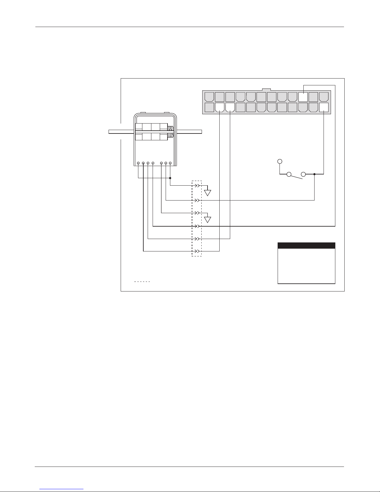
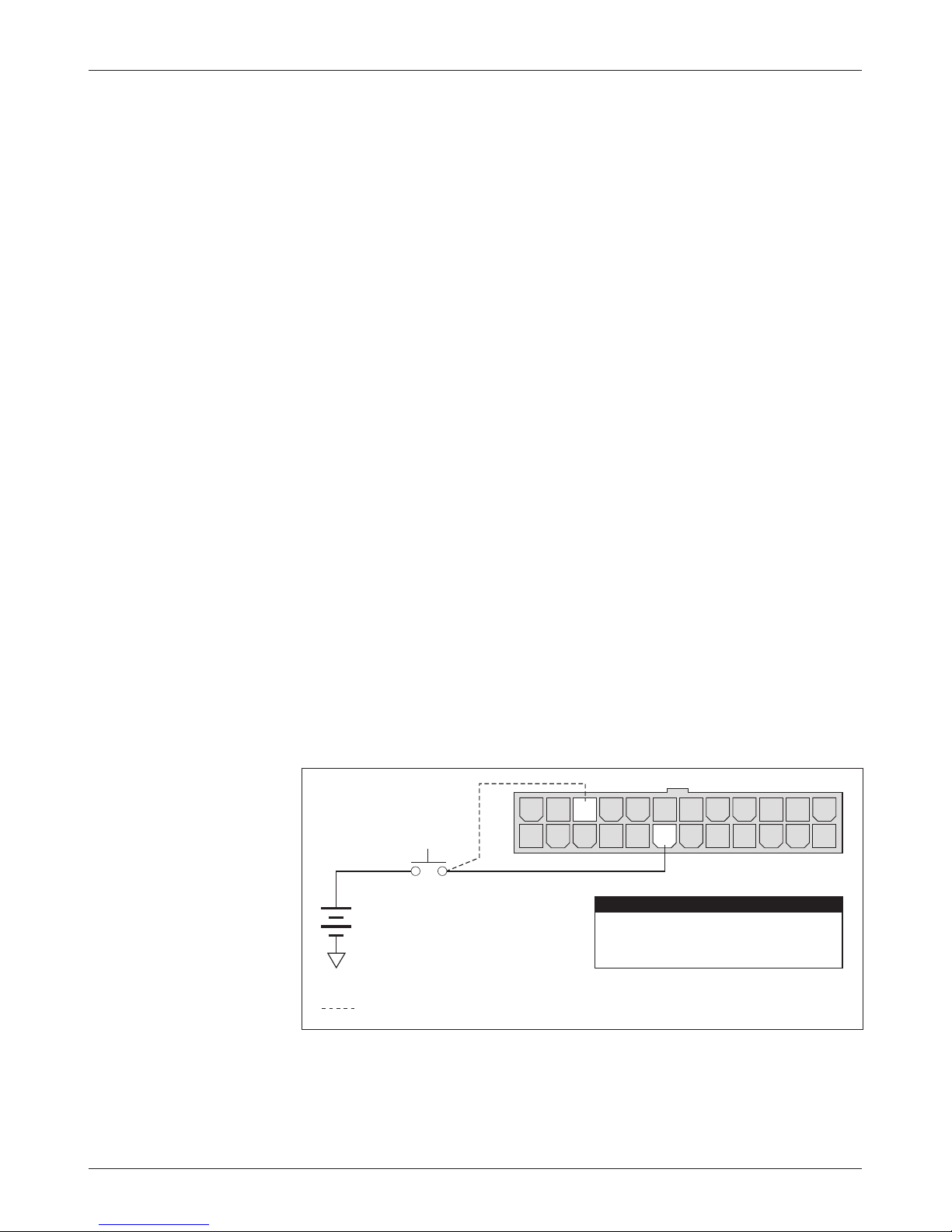
WIRING: Emergency Reverse
If you are installing a 1244 controller in a walkie vehicle, the emergency reverse
switch should be wired to Pin 7, as shown in Figure 13.
Curtis 1244 Manual, Rev. E
gency reverse input is pulled to B+ by closing the emergency reverse switch.
After the emergency reverse switch is released, normal controller operation is
Emergency reverse is activated when the keyswitch is On and the emer-
19
Page 26

2 — INSTALLATION & WIRING: Misc. Features
not resumed until neutral (no direction) is selected or until the interlock switch
CAUTION
☞
is cycled.
operation of the emergency reverse feature. e forward and reverse switches
and the
away from the operator when the emergency reverse button is pressed.
An optional wire connected directly to the emergency reverse switch
provides for broken wire protection when that feature is enabled by the OEM.
e emergency reverse check feature periodically pulses the emergency reverse
circuit to check for continuity in the wiring. If there is no continuity, controller
output is inhibited until the wiring fault is corrected. e emergency reverse
wiring check wire (see dotted line in Figure 13) should be connected to the
emergency reverse switch terminals and to Pin 22.
For information about the emergency reverse parameters, see Section 3:
Programmable Parameters.
CAUTION: e polarity of the F1 and F2 connections will aect the
F1 and F2 connections must be configured so that the vehicle drives
20
Curtis 1244 Manual, Rev. E
Page 27

2 — INSTALLATION & WIRING: Switches, etc.
CONTACTOR, SWITCHES, and OTHER HARDWARE
Main Contactor
A main contactor is recommended for use with any 1244 controller. A main
contactor allows the controller and motor to be disconnected from the battery. is provides a significant safety feature in that the battery power can be
removed from the drive system if a controller or wiring fault results in battery
power being applied to the motor.
A single-pole, single-throw (SPST) contactor with silver-alloy contacts
is recommended for use as the main contactor. It is not necessary to specify
the coils at the nominal battery pack voltage as long as the Contactor Pull-In
Voltage and Contactor Holding Voltage are programmed to accommodate
the coil’s voltage rating—see Section 3, page 46. e contactor coil should be
specified with a continuous rating if the Holding Voltage parameter is to be
set at 100%. Intermittent duty coils can be specified if they are used with appropriate Holding Voltage values.
Keyswitch and Interlock Switch
e vehicle should have a master on/o switch to turn the system o when
not in use. e keyswitch input provides logic power for the controller. e
interlock switch provides a safety interlock to prevent operation when a mechanical brake is engaged or to ensure operator presence before the vehicle is
allowed to move. e keyswitch and interlock switch provide current to drive
the various contactor coils as well as the controller’s internal logic circuitry and
must be rated to carry these currents.
Forward, Reverse, Mode Select, and Pedal Switches
ese input switches can be any type of single-pole, single-throw (SPST) switch
capable of switching the battery voltage at 25 mA.
Reverse Polarity Protection Diode
For reverse polarity protection, a diode should be added to the control circuit.
is diode will prohibit main contactor operation and current ow if the battery
pack is accidentally wired with the B+ and B- terminals reversed. It should be
sized appropriately for the maximum contactor coil and fault diode currents
required from the control circuit. e reverse polarity protection diode should
be wired as shown in the standard wiring diagram (Figure 3, page 8).
Curtis 1244 Manual, Rev. E
21
Page 28

2 — INSTALLATION & WIRING:
Switches, etc.
Circuitry Protection Devices
To protect the control circuitry from accidental shorts, a low current fuse (appropriate for the maximum current draw) should be connected in series with
the battery feed to the keyswitch. Additionally, a high current fuse should be
wired in series with the main contactor to protect the motor, controller, and
batteries from accidental shorts in the power system. e appropriate fuse for
each application should be selected with the help of a reputable fuse manufacturer or dealer. e standard wiring diagram (Figure 3, page 8) shows the
recommended location for each fuse.
Mode Select Switch Operation
e two mode select switches (Mode Select 1 and Mode Select 2) together
define the four operating modes. e switch combinations are shown in Table 2.
Wiring for the mode select switches is shown in the standard wiring diagram
(Figure 3, page 8).
Table 2 MODE SELECTION
MODE MODE
MultiMode™ 1 OPEN OPEN
MultiMode™ 2 CLOSED OPEN
MultiMode™ 3 OPEN CLOSED
MultiMode™ 4 CLOSED CLOSED
OPERATING MODE SELECT SELECT
SWITCH 1 SWITCH 2
22
Curtis 1244 Manual, Rev. E
Page 29

3
3 — PROGRAMMABLE PARAMETERS
PROGRAMMABLE PARAMETERS
e 1244 controller has a number of parameters that can be programmed by
means of a 1313 handheld programmer or 1314 PC Programming Station.
ese programmable parameters allow the vehicle’s performance characteristics
to be customized to fit the needs of individual vehicles or vehicle operators.
Each controller is shipped with the parameter settings specified by the
OEM. For each programmable parameter, the specification process includes
designating whether it is to have User or OEM-only access rights. e OEM
specifies which—if any—parameters the user (dealer, distributor, etc.) will be
able to adjust. Accordingly, Curtis oers two versions of the programmers: for
example, the 1313-1109 is the User handheld programmer (which can adjust
only those parameters with User access rights) and the 1313-4409 is the OEM
programmer (which can adjust all the programmable parameters).
e MultiMode™ feature of these controllers allows operation in four
distinct modes. ese modes can be programmed to provide four dierent
sets of operating characteristics, which can be useful for operating in dierent
conditions—such as slow precise indoor maneuvering in one mode; faster,
long distance, outdoor travel in another mode; and application-specific special
conditions in the remaining two modes.
Eight parameters can be configured independently in the four modes:
— acceleration rate (M1–M4)
— braking rate (M1–M4)
— maximum speed (M1–M4)
— creep speed (M1–M4)
— throttle map (M1–M4)
— throttle braking percent (M1–M4)
— drive current limit (M1–M4)
— braking current limit (M1–M4).
Controllers can be factory-set to allow only one mode of operation if a
MultiMode™ system is not desirable for the application—see Section 4. It is
not necessary to have all eight MultiMode™ parameters on or o together; one
or any combination of these parameters can be specified as single-mode and
the others specified as MultiMode™.
Curtis 1244 Manual, Rev. E
23
Page 30

3 — PROGRAMMABLE PARAMETERS
are listed in the text by the abbreviated names that are displayed by the programmer. Not all of these parameters are displayed on all controllers; the list
for any given controller depends on its specifications.
e manufacturer can specify how these parameters will be configured, but they
are not programmable using the programmer. See Section 4: OEM Specified,
Factory Set Parameters.
e programmable parameters are described in the following order. ey
ere are additional parameters that can only be configured at the factory.
Acceleration Parameters
Acceleration Rate, M1–M4
Braking Rate, M1–M4
Deceleration Rate
Quick Start
Taper Rate
Speed Parameters
Maximum Speed, M1–M4
Creep Speed, M1–M4
Regen Speed
rottle Parameters
Control Mode
rottle Type
rottle Deadband
rottle Maximum
rottle Map, M1–M4
rottle Braking Percent, M1–M4
Current Limit Parameters
Drive Current Limit, M1–M4
Braking Current Limit, M1–M4
Minimum Field Current Limit
Maximum Field Current Limit
Restraint
Emergency Reverse Current Limit
Current Ratio
24
Curtis 1244 Manual, Rev. E
Page 31

3 — PROGRAMMABLE PARAMETERS
Field Control Parameters
Field Map Start
Field Map
Fault Parameters
High Pedal Disable (HPD)
HPD reshold
Static Return to O (SRO)
Fault Code
Output Driver Parameters
Main Contactor Driver Interlock
Main Contactor Dropout Delay
Main Coil Open Check
Main Contactor Weld Check
Auxiliary Driver Dropout Delay
Auxiliary Coil Open Check
Reverse Signal Open Check
Electromagnetic Brake Delay
Electromagnetic Brake Open Check
Contactor Holding Voltage
Contactor Pull-In Voltage
Other Parameters
Battery Voltage
Anti-Tiedown
Sequencing Delay
Pedal Interlock
Emergency Reverse Enable
Emergency Reverse Check
Node Address
Precharge
Load Compensation
Curtis 1244 Manual, Rev. E
25
Page 32

3 — PROGRAMMABLE PARAMETERS: Acceleration Parameters
Acceleration Parameters
M1–M4, ACCEL RATE
e acceleration rate defines the time it takes the controller to accelerate from
0% output to 100% output. A larger value represents a longer acceleration
time and a gentler start. Fast starts can be achieved by reducing the acceleration
time, i.e., by adjusting the accel rate to a smaller value. e acceleration rate is
adjustable from 0.1 second to 5.0 seconds, in 0.1 second increments. It can be
set independently for each of the four operating modes.
M1–M4, BRAKE RATE
e braking rate defines the time it takes the controller to increase from 0%
regen braking current to 100% regen braking current when braking is requested.
A larger value represents a longer time and therefore a gentler increase in braking
strength. Full braking strength is achieved more quickly when the braking rate
parameter value is reduced. e braking rate is adjustable from 0.1 second to
5.0 seconds, in 0.1 second increments, and can be set independently for each
of the four operating modes.
DECEL RATE
e deceleration rate defines the time it takes the controller output to respond
to a decrease in applied throttle. e deceleration rate defines the vehicle’s braking
characteristic for any reduction in throttle, including to neutral, that does not
include a request for the opposite direction. It also defines the characteristic for
braking after Emergency Reverse is released. e decel rate is adjustable from 0
to 10 seconds, in 0.1 second increments. e decel rate works in conjunction
with the throttle braking percent parameter, which must be set greater than zero
for the programmed decel rate to be active. e decel rate is not a MultiMode™
parameter, and its value will therefore aect all four operating modes.
QUICK START
e quick start function provides faster than normal acceleration in response to
fast changes in throttle demand. Upon receiving a sudden high throttle demand
from neutral, the quick start function causes the controller to exceed its normal
acceleration rate. e quick start algorithm is applied each time the throttle
passes through neutral and the controller is not in braking mode. Quick start
is adjustable from 0 to 10, in increments of 1. Increasing the value “livens” the
vehicle’s acceleration response to fast throttle movements.
26
Curtis 1244 Manual, Rev. E
Page 33

TAPER RATE
e taper rate parameter sets the rate at which the regenerative braking command ramps down at the completion of regen braking. is controls the feel of
the vehicle as it slows down and approaches zero speed. e taper rate should
be adjusted such that during a full speed direction transition, the vehicle comes
to a smooth stop before accelerating in the opposite direction. e taper rate
parameter is adjustable from 0 to 64 in increments of 1, with each increment
representing 1/32 of a second. is parameter is not active during plug braking.
Speed Parameters
M1–M4, MAx SPEED
e maximum speed parameter defines the maximum controller output at full
throttle. is parameter is adjustable from 0% to 100%, in 1% increments.
3 — PROGRAMMABLE PARAMETERS: Speed Parameters
M1–M4, CREEP SPEED
e creep speed parameter defines the initial controller output generated when a
direction is first selected. No applied throttle is necessary for the vehicle to enter
the creep mode, only a direction signal. e output maintains creep speed until
the throttle is rotated out of the throttle deadband (typically 10% of throttle).
Creep speed is adjustable from 0% to 25% of the controller duty cycle,
in 1% increments. e specified creep speed percentage is not displayed as a
throttle percent in the programmer’s Test Menu when a direction is selected
and zero throttle is applied; only the throttle command is displayed.
REGEN SPEED
e regen speed parameter defines the vehicle speed above which the controller
initiates regenerative braking; below this speed, plug braking is used. Once the
vehicle begins regen braking, the system will continue to regen brake all the
way to zero speed. is threshold is important as it will aect the smoothness
of direction transitions when jockeying between forward and reverse at low
speeds. Regen braking provides the most benefit when the vehicle is decelerated
from fast speeds, whereas plug braking provides noticeably smoother direction
changes at slow speeds. e regen speed parameter is adjustable from 0% to
100% of the vehicle speed, in 1% increments. Recommendations for adjusting
the regen braking parameter are provided in Section 6: Vehicle Performance
Adjustment.
Curtis 1244 Manual, Rev. E
27
Page 34

3 — PROGRAMMABLE PARAMETERS: Throttle Parameters
rottle Parameters
CTRL MODE
e control mode parameter tailors the controller’s output response to throttle
commands. e two control modes allow the throttle position to define either
applied motor current or applied motor voltage.
In current control mode (Type 0), the throttle position controls the
current owing in the motor. e controller varies the percentage of
battery voltage applied to the motor to achieve the requested motor
current, thus controlling the motor torque. e operator will increase
throttle demand to accelerate and reduce the throttle demand once
the desired vehicle speed is reached. Any conditions that result in an
increase in motor loading or more motor torque will require an increase
in throttle demand to maintain the same vehicle speed. e throttle
braking percent, current ratio, and decel rate parameters are not active
in the current control mode.
In voltage control mode (Type 1), the throttle position controls the
percentage of battery voltage and current applied to the motor. e
current that is allowed to ow in the motor can be modified using the
current ratio parameter; see page 38. In voltage control mode, changes
in motor loading will result in only a small change in vehicle speed
unless the current limit is reached.
Acceleration and deceleration characteristics of the vehicle in response to throttle
changes in any of these modes will be determined by tuning parameters such
as accel rate, quick start, etc.
28
Curtis 1244 Manual, Rev. E
Page 35

3 — PROGRAMMABLE PARAMETERS: Throttle Parameters
ThROTTLE TyPE
e 1244 controller accepts a variety of throttle inputs, through various combinations of its four throttle input pins. e most commonly used throttles
can be hooked up directly: 5kΩ–0 and 0–5kΩ 2-wire rheostats, 3-wire pots,
0–5V throttles, Curtis ET-XXX electronic throttles, and CAN-Nodes based
throttles.
e standard throttle input signal type options—Types “1” through “5” in
the throttle type programming menu—are listed in Table 3. Wiring information
and performance characteristics for each throttle type are presented in Section 2.
Table 3 PROGRAMMABLE ThROTTLE TyPES
THROTTLE
TYPE DESCRIPTION
1 5kΩ–0, 2-wire rheostat
2 single-ended 3-wire potentiometer (1kΩ to 10kΩ range)
or single-ended 0–5V input (from voltage throttle,
Curtis ET-XXX electronic throttle, or current source)
3 0–5kΩ, 2-wire rheostat
4 wigwag 3-wire potentiometer (1kΩ to 10kΩ range)
or wigwag 0–5V input (from voltage throttle)
5 CAN-Nodes throttle
Curtis 1244 Manual, Rev. E
29
Page 36

3 — PROGRAMMABLE PARAMETERS: Throttle Parameters
0–5V Single-Ended Throttle: Type 2
5kΩ–0 Throttle: Type 1
5V
0
0.2V
30% Deadband
10% Deadband
0% Deadband
0.5V
2.0V
5V
0
3.3V
(5.0kΩ)
30% Deadband
10% Deadband
0% Deadband
3.0V
(4.5kΩ)
2.3V
(3.2kΩ)
0.2V
(0Ω)
0.2V
(0Ω)
0.2V
(0Ω)
ThRTL DEADBAND
e throttle deadband parameter defines the throttle pot wiper voltage range
the controller interprets as neutral. Increasing the throttle deadband setting
increases the neutral range. is parameter is especially useful with throttle
assemblies that do not reliably return to a well-defined neutral point, because
it allows the deadband to be defined wide enough to ensure that the controller
goes into neutral when the throttle mechanism is released.
Examples of deadband settings (30%, 10%, 0%) are shown in Figure 14
for throttle types 1 through 4, using a nominal 5kΩ–0 potentiometer. (For
throttle type 5, see the Curtis CAN Protocol Document.)
Fig. 14 Eect of
adjusting the throttle
deadband parameter
(rottle Types 1 and 2).
30
Curtis 1244 Manual, Rev. E
Page 37

0–5V Single-Ended Throttle: Type 2
5kΩ–0 Throttle: Type 1
5V
0
0.2V
30% Deadband
10% Deadband
0% Deadband
0.5V
2.0V
5V
0
3.3V
(5.0kΩ)
30% Deadband
10% Deadband
0% Deadband
3.0V
(4.5kΩ)
2.3V
(3.2kΩ)
0.2V
(0Ω)
0.2V
(0Ω)
0.2V
(0Ω)
3 — PROGRAMMABLE PARAMETERS: Throttle Parameters
Fig. 14, cont’d Eect of
adjusting the throttle
deadband parameter
0
(rottle Types 3 and 4).
1.2V
(1.4kΩ)
0.6V
(450Ω)
0.2V
(0Ω)
0
0.5V
(500Ω)
0.5V
(500Ω)
0–5kΩ Throttle: Type 3
0–5V Wigwag Throttle: Type 4
1.3V
(1.3kΩ)
2.1V
(2.1kΩ)
(2.9kΩ)
2.9V
3.3V
(5.0kΩ)
3.3V
(5.0kΩ)
3.3V
(5.0kΩ)
3.7V
(3.7kΩ)
4.5V
(4.5kΩ)
4.5V
(4.5kΩ)
5V
30% Deadband
10% Deadband
0% Deadband
5V
30% Deadband
10% Deadband
0% Deadband
0.5V
(500Ω)
Throttle
Deadband
KEY
0%
Controller
Output
100%
2.5V
(2.5kΩ)
Notes: Voltages shown are at the pot wiper relative to B-.
For throttle types 1 and 3, the deadband points are
defined in terms of the nominal 5kΩ pot resistance.
Using a pot of greater or lesser resistance will give
different values for the deadband points.
Throttle Max parameter set at 100%.
4.5V
(4.5kΩ)
e programmer displays the throttle deadband parameter as a percentage of the nominal throttle wiper voltage range and is adjustable from 0% to
30%, in 2% increments. e default deadband setting is 10%. e nominal
throttle wiper voltage range depends on the throttle type selected. See Table 1
(page10) for the characteristics of your selected throttle type.
Curtis 1244 Manual, Rev. E
31
Page 38

3 — PROGRAMMABLE PARAMETERS: Throttle Parameters
0–5V Single-Ended Throttle: Type 2
5kΩ–0 Throttle: Type 1
0
5V
2.0V
100% Throttle Max
30% Deadband
0.2V
4.5V
0.2V
3.0V
2.0V
4.5V
90% Throttle Max
30% Deadband
90% Throttle Max
10% Deadband
60% Throttle Max
10% Deadband
0
5V
2.3V
(3.2kΩ)
0.2V
(0Ω)
100% Throttle Max
30% Deadband
3.0V
(4.5kΩ)
1.7V
(2.2kΩ)
0.6V
(450Ω)
90% Throttle Max
30% Deadband
90% Throttle Max
10% Deadband
60% Throttle Max
10% Deadband
0.6V
(450Ω)
2.3V
(3.2kΩ)
3.0V
(4.5kΩ)
ThROTTLE MAx
e throttle max parameter sets the wiper voltage required to produce 100%
controller output. Decreasing the throttle max setting reduces the wiper voltage
and therefore the full stroke necessary to produce full controller output. is
feature allows reduced-range throttle assemblies to be accommodated.
Examples are shown in Figure 15 for throttle types 1 through 4, using a
nominal 5kΩ potentiometer. ese examples illustrate the eect of three different throttle max settings (100%, 90%, 60%) on the full-stroke wiper voltage
required to attain 100% controller output.
Fig. 15 Eect of adjusting
the throttle max parameter
(rottle Types 1 and 2).
32
Curtis 1244 Manual, Rev. E
Page 39

0–5kΩ Throttle: Type 3
0–5V Single-Ended Throttle: Type 2
0–5V Wigwag Throttle: Type 4
0
5V
1.2V
(1.4kΩ)
3.3V
(5.0kΩ)
100% Throttle Max
30% Deadband
0.5V
(400Ω)
2.7V
(3.9kΩ)
3.0V
(4.5kΩ)
90% Throttle Max
30% Deadband
90% Throttle Max
10% Deadband
60% Throttle Max
10% Deadband
Notes: Voltages shown are at the pot wiper relative to B-.
For throttle types 1 and 3, the deadband points are
defined in terms of the nominal 5kΩ pot resistance.
Using a pot of greater or lesser resistance will give
different values for the deadband points.
KEY
100%
Throttle
Deadband
Controller
Output
0%
0
5V
2.0V
100% Throttle Max
30% Deadband
0.2V
4.5V
0.2V
3.0V
2.0V
4.5V
90% Throttle Max
30% Deadband
90% Throttle Max
10% Deadband
60% Throttle Max
10% Deadband
1.7V
(2.2kΩ)
10% Deadband
3.0V
(4.5kΩ)
1.2V
(1.4kΩ)
0.5V
(400Ω)
3.0V
(4.5kΩ)
0
5V
100% Throttle Max
30% Deadband
90% Throttle Max
30% Deadband
90% Throttle Max
10% Deadband
60% Throttle Max
10% Deadband
3.7V
(3.7kΩ)
4.5V
(4.5kΩ)
0.5V
(500Ω)
1.3V
(1.3kΩ)
3.7V
(3.7kΩ)
4.3V
(4.3kΩ)
0.7V
(700Ω)
1.3V
1.3kΩ)
2.9V
(2.9kΩ)
4.3V
(4.3kΩ)
0.7V
(700Ω)
2.1V
(2.1kΩ)
2.9V
(2.9kΩ)
3.7V
(3.7kΩ)
1.3V
(1.3kΩ)
2.1V
(2.1kΩ)
3 — PROGRAMMABLE PARAMETERS: Throttle Parameters
Fig. 15, cont’d
Eect of adjusting the
throttle max parameter
(rottle Types 3 and 4).
the active throttle voltage range. e throttle max parameter can be adjusted
from 100% to 60%, in 2% increments. e nominal throttle wiper voltage
range depends on the throttle type selected. See Table 1 (page 10) for the characteristics of your selected throttle type.
Curtis 1244 Manual, Rev. E
e programmer displays the throttle max parameter as a percentage of
33
Page 40

3 — PROGRAMMABLE PARAMETERS: Throttle Parameters
THROTTLE INPUT (percent of active range)
M1–M4, ThRTL MAP
e throttle map parameter modifies the vehicle’s response to the throttle input.
is parameter determines the controller output, based on the selected throttle
control mode, for a given amount of applied throttle. Setting the throttle map
parameter at 50% provides a linear output response to throttle position. Values
below 50% reduce the controller output at low throttle settings, providing enhanced slow speed control. Values above 50% give the vehicle a faster, jumpier
feel at low throttle settings.
e throttle map can be programmed in 5% increments between 20%
and 80%. e number refers to the controller output at half throttle, as a
percentage of the throttle’s full active range. e throttle’s active range is the
voltage or resistance between the 0% output point (throttle deadband) and the
100% output point (throttle max). For example, if maximum speed is set at
100% and creep speed is set at 0, a throttle map setting of 50% will give 50%
output at half throttle. e 50% setting corresponds to a linear response. Six
throttle map profiles (20, 30, 40, 50, 60, and 80%) are shown as examples in
Figure 16, with the maximum speed set at 100% and the creep speed set 0.
Fig. 16 rottle maps for
controller with maximum
speed set at 100% and
creep speed set at 0.
100
90
80
70
60
50
40
30
20
CONTROLLER OUTPUT (PWM percent)
10
0
THROTTLE MAP
80%
60%
50%
40%
30%
20%
SPEED PARAMETERS
0% Creep Speed
100% Max Speed
100908070605040302010 0
Lowering the max speed or raising the creep speed limits the controller’s
output range. rottle map profiles with the creep speed raised from zero to
10% and the max speed reduced from 100% to 80% are shown in Figure 17.
e throttle map is always a percentage of the controller’s output range. So, in
these examples, the throttle map is a percentage of the 10–80% output range;
a 40% throttle map setting will give 38% output at half throttle (40% of the
70% range, which is 28%, shifted up to 38% because it starts at the 10%
creep speed). Controller output will begin to increase above the set creep speed
as soon as the throttle is rotated out of its normal neutral range (deadband).
Controller output will continue to increase, following the curve defined by the
34
Curtis 1244 Manual, Rev. E
Page 41

THROTTLE INPUT (percent of active range)
THROTTLE INPUT (percent)
CONTROLLER OUTPUT (PWM percent)
100908070605040302010 0
SPEED PARAMETERS
10% Creep Speed
80% Max Speed
THROTTLE
PARAMETERS
15% Deadband
90% Throttle Max
40% Throttle Map
80% Max Speed
40% Throttle Map
(38% output at half throttle)
10% Creep Speed
15% Throttle Deadband
90% Throttle Max
HALF THROTTLE
100
90
80
70
60
50
40
30
20
10
0
3 — PROGRAMMABLE PARAMETERS: Throttle Parameters
throttle map setting, as the throttle input increases and will reach maximum
output when the throttle input enters the upper deadband (crosses the throttle
max threshold).
Fig. 17 rottle maps for
controller with maximum
speed set at 80% and creep
speed set at 10%.
100
90
80
70
60
50
40
30
20
CONTROLLER OUTPUT (PWM percent)
10
0
100908070605040302010 0
THROTTLE MAP
80%
60%
50%
40%
30%
20%
SPEED PARAMETERS
10% Creep Speed
80% Max Speed
e rottle Map operates within the window established by the Creep
Speed, Max Speed, rottle Deadband, and rottle Max parameters, as shown
in Figure 18. Creep Speed and Max Speed define the controller’s output range,
while rottle Deadband and rottle Max define the throttle’s active range.
ese four parameters, together with the rottle Map, determine the controller’s
output response to throttle demand.
Fig. 18 Inuence of various
parameters on controller
output response to throttle
demand.
Curtis 1244 Manual, Rev. E
35
Page 42

3 — PROGRAMMABLE PARAMETERS: Current Limit Parameters
M1–M4, ThRT BRK %
e throttle braking percent parameter establishes the braking force applied to
the vehicle when the throttle is reduced. rottle braking is engaged when the
controller transitions from drive to neutral. e controller recognizes neutral
as the condition where neither direction switch is closed, regardless of throttle
input. is parameter is adjustable from 0% to 100% of the regen braking
current limit specified for a given mode, in 2% increments.
Current Limit Parameters
M1–M4, DRIVE C/L
e drive current limit parameter allows adjustment of the maximum current
the controller will supply to the motor during drive operation. is parameter
can be used to reduce the maximum torque applied to the drive system by the
motor in any of the modes. e drive current limit is adjustable from 200 amps
to the controller’s full rated current, in 5 amp increments. e full rated current
depends on the controller model.
M1–M4, BRAKE C/L
e braking current limit parameter allows adjustment of the maximum current the controller will supply to the motor during regen braking operations.
During regen braking, this parameter controls the regen current from the
motor’s armature into the battery. e braking current limit is adjustable from
100 amps up to the controller’s full rated current, in 5 amp increments. e
full rated current depends on the controller model.
FIELD MIN
e minimum field current limit parameter defines the minimum allowed
current in the motor’s field winding. Its setting will determine the vehicle’s
maximum speed and, to some extent, the smoothness with which the vehicle
starts and transitions from one direction to another. If the Field Min value is set
high, the vehicle’s top speed will be reduced, but torque bumps may be evident
when the vehicle is inched or changes direction.
One of the greatest advantages of the Field Min parameter is that it will
prevent uncontrolled acceleration when the vehicle encounters a decline. e
vehicle’s speed is limited when it goes down ramps or when it is unloaded from
trucks, etc.
e Field Min parameter is adjustable from 2 to 20 amps, in 0.5 amp
increments. Recommendations for adjusting the Field Min parameter are provided in Section 6: Vehicle Performance Adjustment.
36
Curtis 1244 Manual, Rev. E
Page 43

3 — PROGRAMMABLE PARAMETERS: Current Limit Parameters
FIELD MAx
e maximum field current limit parameter defines the maximum allowed
current in the motor’s field winding. Its setting will determine the motor’s
maximum torque during both drive and braking, and will limit the power
dissipation in the field winding itself. e Field Max parameter is adjustable
from 7.5 amps to the controller’s full rated field current limit, in 0.5 amp increments. Recommendations for adjusting the Field Max parameter are provided
in Section6: Vehicle Performance Adjustment.
RESTRAINT
Because the 1244 controller is configured to provide throttle braking, overspeed
will cause the controller to create a braking current and thus limit or “restrain”
the overspeed condition. e restraint parameter, in combination with throttle
braking percent parameter, determines how strongly the controller will attempt
to limit the vehicle speed to the existing throttle setting. is function works
at all throttle settings, including zero throttle. It is applicable when throttle is
reduced or when the vehicle begins to travel downhill.
e restraint parameter is adjustable from 1 to 10. Setting the parameter to a high value will cause strong braking, in an eort to bring the vehicle
speed down to the requested speed. Setting the restraint value to 1 will result
in minimal regen braking.
At zero throttle, the restraint function will also attempt to keep the motor
at zero speed. is will help hold the vehicle from running away down ramps
when braking to neutral is completed and the mechanical or electromagnetic
brake has not engaged. e higher the restraint parameter value, the stronger the
braking force applied to the motor and the slower the vehicle will creep down
the ramp. is creeping speed will depend on the restraint setting, the steepness
of the ramp, and the vehicle load. e restraint feature can never hold a vehicle
perfectly stationary on a ramp and is not intended to replace a mechanical or
electromagnetic brake for this purpose. e throttle braking percent parameter
is not active in this situation, and the controller will supply up to the maximum
programmed regen current limit. Recommendations for adjusting the restraint
parameter are provided in Section 6: Vehicle Performance Adjustment.
Curtis 1244 Manual, Rev. E
37
Page 44

3 — PROGRAMMABLE PARAMETERS: Field Control Parameters
EMR REV C/L
e emergency reverse current limit parameter defines the maximum braking
current provided through the motor when the emergency reverse function is
engaged. e emergency reverse current limit is adjustable from 50 amps to the
controller’s full rated braking current limit, in 5 amp increments.
CURRENT RATIO
e current ratio parameter defines how much of the programmed drive current
will be available to the motor at reduced throttle requests. is will determine
the maximum torque the motor can provide at partial throttle. e current ratio
parameter can be set to 1, 2, 4, or 8. ese settings represent a multiplication
factor applied to the current that would otherwise be available. For example,
if 20% throttle is requested with the current ratio set at 1, 20% of the battery
voltage and 20% of the drive current will be allowed to ow in the motor (assuming a 50% throttle map setting). If the current ratio is set at 2 under these
same conditions, 40% of the current will be available; if it is set at 4, 80%. e
controller will never allow more than the programmed drive current to ow
in the motor. If the current ratio is set at 8 with 20% throttle requested, the
controller will allow only 100% of the drive current and not 160%.
Because the current ratio parameter aects how much torque the motor
can provide, high current ratio settings will result in improved ramp climbing
with partial throttle, but may cause too much jumpiness at startup.
: e current ratio parameter is valid only when the control mode
parameter is set to Type 1 (Voltage Control).
38
Field Control Parameters
FLD MAP START
e field map start parameter defines the armature current at which the field
map starts to increase from the Field Min value. is parameter is expressed in
amperes, and is adjustable from 0 to one half the controller’s full rated armature
current value, in 5 amp increments. e Field Map Start parameter is used to
equalize the vehicle’s maximum speed when loaded and unloaded.
Increasing the Field Map Start value increases the maximum load the
vehicle can carry while still maintaining maximum speed on a level surface.
Whether the vehicle’s loaded speed will actually increase depends on the armature current being drawn at that load. If the armature current is already below
the Field Map Start setting, increasing the Field Map Start value will not aect
the vehicle’s loaded speed.
Curtis 1244 Manual, Rev. E
Page 45

3 — PROGRAMMABLE PARAMETERS: Field Control Parameters
Care should be taken to ensure that high Field Map Start values do not
move the motor’s operating characteristics outside its safe commutation area.
Recommendations for adjusting the Field Map Start parameter to achieve various performance characteristics are provided in Section 6: Vehicle Performance
Adjustment Guidelines.
FIELD MAP
e field map parameter defines the variation of the field winding current as a
function of armature current. It controls how much field current is applied for a
given armature current, and is adjustable from 0% to 100%, in 5% increments.
e Field Map parameter is set as a percentage of the field current between
the Field Min and Field Max values. As shown in Figure 19, the Field Map
parameter increases or decreases the field current at the armature current that is
halfway between the Field Map Start current and the controller’s programmed
drive current limit. is point on the armature current curve is referred to as
the Field Map Midpoint.
With the Field Map set at 50% and the Field Map Start set at zero, the
motor’s field current increases linearly with increasing armature current—thus
emulating a series wound motor. Decreasing the field map setting reduces the
field current at a given armature current, i.e., it weakens the field. As the field
current is reduced, the motor will be able to maintain speeds closer to the
maximum speed value.
Care should be taken to ensure that excessively low Field Map values do
not move the motor’s operating characteristics outside its safe commutation
region. Recommendations for adjusting the Field Map parameter to achieve
various performance characteristics are provided in Section 6: Vehicle Performance Adjustment Guidelines.
Curtis 1244 Manual, Rev. E
39
Page 46

3 — PROGRAMMABLE PARAMETERS: Field Control Parameters
Fig. 19 Field current
relative to armature
Field Max
current, with field map
parameter set at 50%
and 20%.
Field Map
(50%)
FIELD CURRENT
Field Min
0
0
Field Max
Field Map Start Field Map Midpoint 100%
ARMATURE CURRENT
Field Map
(20%)
FIELD CURRENT
Field Min
0
0
Field Map Start Field Map Midpoint 100%
ARMATURE CURRENT
40
Curtis 1244 Manual, Rev. E
Page 47

Fault Parameters
3 — PROGRAMMABLE PARAMETERS: Fault Parameters
hPD
e high pedal disable (HPD) feature prevents the vehicle from driving the motor
if greater than HPD reshold throttle is applied when the controller is turned on.
In addition to providing routine smooth starts, HPD also protects against accidental sudden starts if problems in the throttle linkage (e.g., bent parts, broken return
spring) give a throttle input signal to the controller even with the throttle released.
If the operator attempts to start the vehicle with the throttle already applied, the controller will inhibit output to the motor until the throttle is reduced
below HPD reshold. For the vehicle to run, the controller must receive
a KSI input [Type 1],
a KSI input and an interlock input [Type 2], or
a KSI input, an interlock input, and a direction input [Type 3],
before receiving a throttle input. Either of these three types of HPD can be
selected via the programmer. HPD can also be disabled [Type 0]. To meet EEC
requirements, the HPD feature must be programmed to Type 1 or 2. To meet
MSHA requirements, HPD must be programmed to Type 3.
Sequencing delay (see page 47) can be used to provide a variable delay
before the controller is disabled, if desired.
No HPD (Type 0)
HPD function is disabled.
Interlock-type HPD (Type 1)
To start the vehicle, the controller must receive an interlock switch input in
addition to a KSI input before receiving a throttle input. Controller operation
will be disabled immediately if throttle input is greater than HPD reshold at
the time the interlock switch is closed. Normal controller operation is regained
by reducing the throttle demand to less than HPD reshold.
KSI-type HPD (Type 2)
To start the vehicle, the controller must receive a KSI input before receiving
a throttle input. Controller operation will be disabled immediately if throttle
input is greater than HPD reshold at the time KSI is enabled. If throttle is
applied before the interlock switch is closed but after the KSI input has been
enabled, the vehicle will accelerate to the requested speed as soon as the interlock switch is closed. Normal operation is regained by reducing the throttle
demand to less than HPD reshold.
Golf-type HPD (Type 3)
To start the vehicle, the controller must receive a direction input in addition
to an interlock switch input and a KSI input before receiving a throttle input.
Controller operation will be disabled immediately if throttle input is greater
Curtis 1244 Manual, Rev. E
41
Page 48

3 — PROGRAMMABLE PARAMETERS: Fault Parameters
than HPD reshold at the time the direction switch is closed or is changed
while driving. Normal controller operation is regained by reducing the throttle
demand to less than HPD reshold.
hPD ThREShOLD
e HPD threshold parameter denes the maximum throttle allowed at startup.
If throttle is greater than this threshold at startup, an HPD fault is issued. is
parameter has a default setting of 25%, and is programmable from 0 to 25%.
SRO
e static return to o (SRO) feature prevents the vehicle from being started
when “in gear.” SRO checks the sequencing of the interlock input—or the interlock input and KSI—relative to a direction input. e interlock input—or
the interlock plus KSI inputs—must come on before a direction is selected.
If a direction is selected before or simultaneously (within 50 msec) with the
interlock input, the controller is disabled.
ree types of SRO are available (along with a “no SRO” option):
Type 0: no SRO
Type 1: SRO on interlock input plus a direction input
Type 2: SRO on KSI plus interlock input plus a direction input
Type 3: SRO on KSI plus interlock input plus forward direction input.
If your controller is programmed so that both KSI and interlock inputs
are required (SRO Type “2”), the following sequence must be followed to enable
the controller: 1, turn on KSI; 2, activate interlock (input “high”);
and then 3, select a direction. e interval between steps 1 and 2 is the
same as between steps 2 and 3; that is, KSI input must precede interlock input
by at least 50 msec. Once the controller is operational, turning o either KSI
or the interlock causes the controller to turn o; re-enabling the controller
requires the 3-step sequence.
Similarly, if your controller is programmed so that KSI, interlock, and
forward inputs are all required (SRO Type “3”), they must be provided in that
sequence in order to enable the controller. Note, however, that operation is
allowed if a reverse input precedes the interlock input; this can be useful when
operating a walkie on ramps.
Sequencing delay (see page 47) can be used to provide a variable delay
before disabling the controller, if desired.
FAULT CODE
e 1244 controller’s fault code drivers allow faults to be displayed in either of
two dierent formats: Fault Code format or Fault Category format.
42
Curtis 1244 Manual, Rev. E
Page 49

3 — PROGRAMMABLE PARAMETERS: Output Driver Parameters
With the fault code parameter specified “On,” the controller’s fault outputs
will provide information in Fault Code format. With the fault code parameter
specified “O,” the controller’s fault outputs will provide information in Fault
Category format.
In Fault Code format, the two fault lines operate independently. When a
fault is present, the Fault 1 driver (Pin 5) provides a pulsed signal equivalent to
the fault code ashed by the controller’s built-in Status LED. is signal can be
used to drive an LED located on the display panel to provide the fault code information to an operator, or to any remote panel. e Fault 2 driver (Pin 6) pulls
low (to B-) and remains on until the fault is cleared; it can also be used to drive a
remote LED. When no faults are present, these outputs will both be open (o).
In Fault Category format, the two fault lines together define one of four
fault categories. Table 4 describes the four fault categories, shows the state of
the two outputs for each category, and lists the faults that might be present
when each of the four fault category signals is transmitted.
Table 4 FAULT CATEGORIES
FAULT FAULT 1 FAULT 2
CATEGORY OUTPUT OUTPUT POSSIBLE EXISTING FAULTS
(Pin 5) (Pin 6)
0 HIGH HIGH (no faults present, or controller not operational)
1 LOw HIGH HW Failsafe; M-, Current Sensor, or Motor Fault;
Throttle Fault; Emergency Reverse Wiring Fault;
Contactor or Output Driver Fault; Precharge Fault
2 HIGH LOw Low Battery Voltage; Overvoltage; Thermal Cutback
3 LOw LOw HPD; SRO; Anti-Tiedown
Output Driver Parameters
MAIN CONT INTR
e main contactor driver interlock parameter allows the manufacturer to
define a dual switch requirement to operate the vehicle. When this parameter
is set to “On,” the controller requires that both the KSI input (Pin 1) and the
interlock input (Pin 2) be pulled high (to B+) before the controller will engage
the main contactor. e main contactor will open after the interlock switch is
opened and the sequencing and main open delays expire. If this parameter is set
to “O,” only the KSI input is required for the main contactor to be engaged.
MAIN OPEN DLy
e main contactor dropout delay parameter is applicable only if the main
contactor driver interlock parameter has been set to “On.” e dropout delay
Curtis 1244 Manual, Rev. E
43
Page 50

3 — PROGRAMMABLE PARAMETERS: Output Driver Parameters
parameter can then be set to allow the main contactor to remain closed for
a period of time after the interlock switch is opened. e delay time is programmable from zero to 40 seconds, in 1 second intervals. e delay is useful
for preventing unnecessary cycling of the main contactor and for maintaining
power to auxiliary functions, such as a steering pump motor, that may be used
for a short time after the brake has been applied or the operator has gotten up
from the seat.
MAIN ChECK
e main coil open check parameter defines whether the controller performs
missing coil checks to ensure that the main contactor has closed properly.
When this parameter is set to “On,” the controller senses the voltage at the
main driver input (Pin 17) to confirm that the main contactor coil is properly
connected, and also tests that the main contactor has indeed closed each time
it is commanded to do so. If the criteria for either of these tests are not met,
the controller will inhibit operation and issue a fault. Neither of these tests is
performed if the main check parameter is set to “O.”
wELD ChECK
e main contactor weld check parameter defines whether the controller tests
the main contactor to ensure that it is not welded closed. If the weld check
parameter is set to “On,” this check is performed when the keyswitch is first
engaged and then each time the main contactor is commanded to open. is
check is not performed if the parameter is set to “O.”
AUx DELAy
e auxiliary driver dropout delay parameter can be set to allow the auxiliary
driver to remain active for a period of time after the interlock switch is opened.
e delay time is programmable from 0 to 10 seconds, in 0.1 second intervals.
: e auxiliary driver dropout delay parameter is applicable only if
the accessory driver enable has been specified “On.” e accessory driver enable
is a factory-set parameter, and is described in Section 4.
AUx ChECK
e auxiliary coil open check parameter defines whether the controller performs missing coil checks on the auxiliary driver output. When this parameter
is set to “On,” the controller senses the voltage at the auxiliary driver output
(Pin18) to confirm that the auxiliary contactor coil is properly connected. If
44
Curtis 1244 Manual, Rev. E
Page 51

3 — PROGRAMMABLE PARAMETERS: Output Driver Parameters
the criteria for this test are not met, the controller will inhibit operation and
issue a fault. is test is not performed if the aux check parameter is set to “O.”
Note: e aux check parameter is applicable only if the accessory driver
enable has been specified “On.” e accessory driver enable is a factory-set
parameter, and is described in Section 4.
REV DRVR ChECK
e reverse signal open check parameter defines whether the controller
performs missing load checks on the reverse signal driver output. When this
parameter is set to “On,” the controller senses the voltage at the reverse signal
driver output (Pin 19) to confirm that the reverse signal driver load is properly
connected. If the criteria for this test are not met, the controller will inhibit
operation and issue a fault. is test is not performed if the reverse signal open
check parameter is set to “O.”
Note: e reverse signal open check parameter is applicable only if the
accessory driver enable has been specified “On.” e accessory driver enable is
a factory-set parameter, and is described in Section 4.
EM BRAKE DELAy
e electromagnetic brake delay parameter is applicable only if the accessory
driver enable has been specified “On.” e accessory driver enable is a factory-set
parameter, and is described in Section 4.
e electromagnetic brake delay parameter can be set to delay engaging
the electromagnetic brake for a specified period of time after the controller
senses that braking has been completed and the vehicle has come to a stop.
e delay time is programmable from 0 to 5 seconds, in 0.1 second intervals.
EM BRAKE ChECK
e electromagnetic brake open check parameter defines whether the controller performs missing coil checks on the electromagnetic brake driver output.
When this parameter is set to “On,” the controller senses the voltage at the
electromagnetic brake driver output (Pin 20) to confirm that the electromagnetic
brake coil is properly connected. If the criteria for this test are not met, the
controller will inhibit operation and issue a fault. is test is not performed if
the electromagnetic brake open check parameter is set to “O.”
Note: e electromagnetic brake open check parameter is applicable only
if the accessory driver enable has been specified “On.” e accessory driver
enable is a factory-set parameter, and is described in Section 4.
Curtis 1244 Manual, Rev. E
45
Page 52

3 — PROGRAMMABLE PARAMETERS: Other Parameters
CONT hOLDING
e contactor holding voltage parameter defines the output duty cycle of
the main, auxiliary, reverse, and electromagnetic brake drivers. is parameter
is adjustable from 20% to 100% of the battery voltage, in 2% increments. It
allows the OEM to reduce the average applied voltage so that a contactor coil
or other load that is not rated for the full battery voltage can be used.
For example, contactor coils rated for 12V could be used with a 36V
system if the contactor holding voltage parameter were set to 34%. e parameter can be set lower than the rated contactor coil voltage, as long as it is
set high enough to hold the contactor closed under all shock and vibration
conditions the vehicle will be subjected to. Low settings minimize the current
required to power the coil, thereby reducing coil heating and increasing battery
life. Recommended values for the contactor holding voltage parameter should
be determined with specifications or advice from the contactor manufacturer.
is parameter aects all the driver outputs, so the loads on each driver
must allow operation at the set holding voltage. In addition, the loads on each
driver must be compatible with a PWM signal (if the parameter is set to a value
less than 100%), as the output is pulse width modulated.
CONT PULL IN
e contactor pull-in voltage parameter sets the peak voltage applied to the
loads connected to the main, auxiliary, reverse and electromagnetic brake drivers.
Typically these loads are contactor coils. e pull-in parameter allows a high
initial voltage to be supplied when the driver first turns on, to ensure contactor
closure. After 0.1 second, the driver voltage drops to the value specified by the
contactor holding voltage parameter. Recommended values for this parameter
should be determined with specifications or advice from the contactor manufacturer. is parameter is adjustable from 20% to 100% of the nominal battery
voltage, in 2% increments.
Other Parameters
VOLTAGE
e battery voltage parameter sets the overvoltage and undervoltage protection
thresholds for the electronic system. is parameter determines when regen
should be cut back to prevent damage to batteries and other electrical system
components due to overvoltage. Similarly, the undervoltage threshold protects
systems from operating at voltages below their design thresholds. is will
ensure proper operation of all electronics whenever the vehicle is driven. e
46
Curtis 1244 Manual, Rev. E
Page 53

3 — PROGRAMMABLE PARAMETERS: Other Parameters
battery voltage parameter can be set from 2 to 7, and should always be set to
the system’s nominal battery pack voltage:
... .. .. ...
2 24V 14V 16V 28V 31V
3 36V 22V 23.8V 43V 46V
4 48V 24V 32V 55V 61V
5 60V 37V 39V 70V 76V
6 72V 46V 49V 85V 92V
7 80V 52V 57V 97V 105V
.. = Severe Under Voltage (causes reset)
. = Under Voltage
. = Over Voltage
.. = Severe Over Voltage (causes reset)
ANTI-TIEDOwN
e anti-tiedown feature prevents operators from taping or “tying down” the
mode select switches in order to operate permanently in Mode 2 or Mode 4.
On startup, when the interlock switch is first closed, the anti-tiedown feature
checks which operational mode is selected. If the mode select switches are requesting Mode 2 or Mode 4, the controller will ignore the request and default
to Mode 1 or Mode 3 respectively. e controller will remain in Mode 1 or
Mode 3 until the Mode Select 1 switch is released and reactivated.
Anti-tiedown is primarily used in walkie applications. It can be pro-
grammed “On” or “O.”
Curtis 1244 Manual, Rev. E
SEQUENCING DLy
e sequencing delay feature allows the interlock switch to be cycled within
a set time (the sequencing delay), in order to prevent inadvertent activation of
HPD or SRO. is feature is useful in applications where the interlock switch
may bounce or be momentarily cycled during operation. e sequencing delay
parameter can be set from 0 to 3 seconds, in increments of 0.1 second, with 0
corresponding to no delay.
PEDAL INTR
e pedal interlock parameter can be programmed as “On” or “O.” When
“On,” it requires that the pedal switch input (Pin 8) be active (pulled to B+)
before the controller will supply power to the motor. is feature is useful in
systems that use a seat or foot switch to guarantee operator presence for vehicle
operation. Alternatively, a switch connected to the brake pedal can be configured
47
Page 54

3 — PROGRAMMABLE PARAMETERS: Other Parameters
to open immediately so that motor drive is disabled and will not interfere with
the mechanical braking function. In this arrangement, when the brake pedal is
released the controller output accelerates through its programmed acceleration
curve to the existing throttle request.
e controller does not require the pedal signal to engage the main
contactor, and the main contactor will not cycle on and o when the pedal
switch is opened and closed.
EMR REV ENABLE
e emergency reverse enable parameter enables or disables the emergency
reverse function. When it is set to “On,” the controller will be prepared to
implement the emergency reverse current limit for enhanced braking and the
direction change to reverse when the emergency reverse input (Pin 7) is pulled
high (to B+). When the emergency reverse enable parameter is set to “O,” the
controller will not respond to any input to Pin 7 and the emergency reverse
current limit and emergency reverse check parameters will not be active.
EMR REV ChECK
e emergency reverse check parameter is applicable only when the emergency
reverse feature is being used in the application. If emergency reverse is not being
used, this parameter should be set to “O.”
When enabled (programmed “On”), the emergency reverse check tests
for continuity from the emergency reverse check output (Pin 22) to the emergency reverse input (Pin 7). erefore, the emergency reverse wiring should be
connected as closely as possible to the controller side of the emergency reverse
switch, as shown in Figure 13. If the controller detects this open wire fault,
it will disable its output until the wiring fault is fixed. e emergency reverse
function will still be active when this fault exists.
NODE ADDR
e node address parameter determines which address the controller will
respond to when used with a CAN Bus communications system. e address
can be specified from 1 to 15. is parameter is valid only when the CAN Bus
function has been specified for the controller; see Section 4.
48
Curtis 1244 Manual, Rev. E
Page 55

3 — PROGRAMMABLE PARAMETERS: Other Parameters
PRECHARGE
e precharge parameter enables or disables the precharge function. When
this parameter is set to “On,” the precharge function does not close the main
contactor until the internal power capacitor bank charges to within 10% of the
battery voltage. Charging is accomplished internally and an external precharge
resistor is not required. If the capacitor voltage does not reach this theshold, a
precharge fault is issued and the main contactor is never closed. is reduces
inrush current stresses on the capacitor bank and provides protection against
allowing full battery power to be engaged if there is a short in the output section.
Setting the parameter to “O” disables the precharge function. e precharge
function is required for systems using 48V (or higher) battery packs.
LOAD COMP
e load compensation parameter actively adjusts the applied motor voltage as
a function of motor load current. is results in more constant vehicle speeds
over variations in load and in driving surface (ramps, etc.) without the vehicle
operator having to constantly adjust the throttle position. is parameter will
also help equalize loaded and unloaded vehicle speeds. Higher load compensation
values will cause the controller to be more aggressive in attempting to maintain
vehicle speed. However, too much load compensation can result in jerky vehicle
starts and speed oscillation (“hunting”) when the vehicle is unloaded.
e load compensation parameter is adjustable from 0 to 25. Recommendations for adjusting this parameter are provided in Section 6: Vehicle
Performance Adjustment.
Curtis 1244 Manual, Rev. E
49
Page 56

4 — OEM-SPECIFIED, FACTORY-SET PARAMETERS
In addition to the programmable parameters described in Section 3, there are
4
three parameters that can be set at the factory per the OEM’s specification:
— MultiMode™ Enable
— Accessory Driver Enable
— CAN Bus Enable
ese parameters are not programmable with the 1313 handheld programmer
or 1314 PC Programming Station. If a change is desired, the controller must
be returned to an authorized Curtis facility for reconfiguration.
MULTIMODE™ ENABLE
A key feature of Curtis MultiMode™ controllers is their capability of being
configured for optimized performance in four distinctly defined modes. However, should the OEM prefer to oer only a single mode of operation in a
given application, the MultiMode™ feature can be disabled. Each of the 1244
controller’s eight MultiMode™ parameters can be individually defined as MultiMode™ or single mode.
OEM specifies
OEM-SPECIFIED PARAMETERS
(SET AT FACTORy)
➤ On or O Default setting ➤ On
ACCESSORy DRIVER ENABLE
e 1244 controller provides three accessory drivers: an auxiliary driver (Pin 18),
a reverse signal driver (Pin 19), and an electromagnetic brake driver (Pin 20).
e auxiliary driver (Pin 18) provides a connection to B- when KSI and
the interlock (if enabled) are activated. e driver will release after the
programmed auxiliary driver dropout delay when the interlock switch
is turned o.
e reverse signal driver (Pin 19) provides a connection to B- whenever
the vehicle is moving in reverse, regardless of whether it is driving or
braking. When the vehicle is moving forward or is in neutral, the output
remains open. e reverse signal driver provides a continuous connection to B- (or a 500Hz pulsed signal if the contactor holding voltage
is set at less than 100%) but is not intended to pulse an audible alarm.
e electromagnetic brake driver (Pin 20) will engage (pull to B-) when
the throttle is applied or when creep speed is greater than zero and a
direction is selected. It will release, after the programmed electromagnetic
driver delay, when the throttle is returned to neutral or when the vehicle has come to a stop. When the electromagnetic brake driver is used,
the neutral braking parameter must be set to a value greater than zero.
50
Curtis 1244 Manual, Rev. E
Page 57

4 — OEM-SPECIFIED, FACTORY-SET PARAMETERS
When the accessory driver enable is specified “On,” these three drivers are enabled. If none of these drivers is required, the accessory driver enable parameter
should be specified as “O.”
Each accessory driver output is rated at 2 amperes and is monitored for
open connection and overcurrent faults. An internal diode provides coil suppression through the coil return output (Pin 9). Wiring for the accessory drivers
is shown in Figure 12, page 18.
When the accessory driver enable is specified “On,” it also enables various
programmable parameters associated with the accessory drivers: the auxiliary
driver dropout delay, the auxiliary coil open check, the reverse signal open check,
the electromagnetic brake dropout delay, and the electromagnetic brake open
check. For more information on these programmable parameters, see Section 3.
Any component can be controlled by any of the accessory outputs provided
its current requirements do not exceed the driver’s 2 amp rating.
e three accessory drivers are enabled or disabled as a group; it is not
possible, for example, to have the electromagnetic brake driver enabled and the
auxiliary driver and reverse signal driver disabled.
OEM specifies
➤ On or O Default setting ➤ On
CAN BUS ENABLE
When enabled, this parameter configures the 1244 controller for use with
CAN-based control systems.
OEM specifies
➤ On or O Default setting ➤ O
Curtis 1244 Manual, Rev. E
51
Page 58

5 — INSTALLATION CHECKOUT
5
INSTALLATION CHECKOUT
Before operating the vehicle, carefully complete the following checkout procedure. If you find a problem during the checkout, refer to the diagnostics and
troubleshooting section (Section 8) for further information.
e installation checkout can be conducted with or without a 1313 handheld programmer or 1314 PC Programmig Station. e checkout procedure is
easier with a programmer. Otherwise, observe the Status LED (located in the
controller’s label area) for diagnostic codes. e codes are listed in Section 8.
CAUTION
☞
Put the vehicle up on blocks to get the drive wheels up
o the ground before beginning these tests.
Do not stand, or allow anyone else to stand, directly in
front of or behind the vehicle during the checkout.
Make sure the keyswitch is o, the throttle is in neutral,
and the forward and reverse switches are open.
Wear safety glasses and use well-insulated tools.
1. If a programmer is available, connect it to the programmer connector.
2. Turn the keyswitch on. e programmer should power up with an initial
display, and the controller’s Status LED should begin steadily blinking
a single ash. If neither happens, check for continuity in the keyswitch
circuit and controller ground.
3. If you are using a programmer, select the Diagnostics Menu, and open
the Present Faults folder. e display should indicate “No Known Faults.”
Close the interlock switch (if one is used in your application). e Status
LED should continue blinking a single ash and the programmer should
continue to indicate no faults.
If there is a problem, the LED will flash a diagnostic code and the
programmer will display a diagnostic message. If you are conducting
the checkout without a programmer, look up the LED diagnostic code
in Section 8 (Diagnostics and Troubleshooting).
When the problem has been corrected, it may be necessary to cycle
the keyswitch in order to clear the fault.
52
Curtis 1244 Manual, Rev. E
Page 59

5 — INSTALLATION CHECKOUT
4. With the interlock switch closed, select a direction and operate the
throttle. e motor should begin to turn in the selected direction. If it
turns in the wrong direction, first verify the wiring to the forward and
reverse switches. If the wiring is correct, turn o the controller, disconnect the battery, and exchange the motor’s field connections (
F1 and F2)
on the controller. e motor should now turn in the proper direction.
e motor should run proportionally faster with increasing throttle. If
not, refer to Section 8.
5. If you are using a programmer, select the Monitor Menu. Scroll down to
observe the status of the forward, reverse, interlock, emergency reverse,
and mode switches. Cycle each switch in turn, observing the programmer. e programmer should display the correct status for each switch.
6. Take the vehicle down o the blocks and drive it in a clear area. It
should have smooth acceleration and good top speed. Recommended
procedures for tuning the vehicle’s driving characteristics are presented
in Section 6: Vehicle Performance Adjustment.
7. Test the deceleration and braking of the vehicle.
8. Verify that all options, such as high pedal disable (HPD), static return
to o (SRO), and anti-tiedown are as desired.
9. On walkie vehicles, check the emergency reverse feature. If you have the
optional emergency reverse check wiring, verify that the check circuit is
operational by momentarily disconnecting one of the emergency reverse
wires. e vehicle should coast to a stop, with a fault indicated.
10. If you used a programmer, disconnect it when you have completed the
checkout procedure.
Curtis 1244 Manual, Rev. E
53
Page 60

6 — VEHICLE PERFORMANCE ADJUSTMENT
e 1244 controller is a very powerful vehicle control system. Its wide variety of
6
adjustable parameters allow many aspects of vehicle performance to be optimized.
is section provides explanations of what the major tuning parameters do and
instructions on how to use these parameters to optimize the performance of
your vehicle. Once a vehicle/motor/controller combination has been tuned, the
parameter values can be made standard for that system or vehicle model. Any
changes in the motor, the vehicle drive system, or the controller will require
that the system be tuned again to provide optimum performance.
e tuning procedures should be conducted in the sequence given, because
successive steps build upon the ones before. e tuning procedures instruct
personnel how to adjust various programmable parameters to accomplish specific
performance goals. It is important that the eect of these programmable parameters be understood in order to take full advantage of the 1244 controller’s
powerful features. Please refer to the descriptions of the applicable parameters
in Section 3 if there is any question about what any of them do.
VEHICLE PERFORMANCE ADJUSTMENT
MAJOR TUNING
Four major performance characteristics are usually tuned on a new vehicle:
ese four characteristics should be tuned in the order listed.
Tuning the Active Throttle Range
➀
Before attempting to optimize any specific vehicle performance characteristics,
it is important to ensure that the controller output is operating over its full
range. To do this, the throttle should be tuned using the programmer. e
procedures that follow will establish rottle Deadband and rottle Max
parameter values that correspond to the absolute full range of your particular
throttle mechanism. It is advisable to provide some buer around the absolute
full range of the throttle mechanism to allow for throttle resistance variations
over time and temperature as well as variations in the tolerance of potentiometer
values between individual throttle mechanisms.
➀ Tuning the Active rottle Range
➁ Tuning the Controller to the Motor
➂ Setting the Unloaded Vehicle Top Speed
➃ Equalization of Loaded/Unloaded Vehicle Speed.
54
Curtis 1244 Manual, Rev. E
Page 61

6 — VEHICLE PERFORMANCE ADJUSTMENT
-A Tuning the rottle Deadband
➀
1. Jack the vehicle wheels up o the ground so that they spin freely.
2. Plug the programmer into the controller and turn on the key-
switch and interlock switch (if used).
3. When the programmer instructs you to select a menu, select the
Monitor Menu. e rottle % should be visible at the top of
the display. You will need to reference the value displayed here.
4. Scroll down until the Forward Input is visible. e display should
indicate that the forward switch is O.
5. Slowly rotate the throttle forward until the display indicates
that the forward switch is On. Use care with this step as it is
important to identify the threshold throttle position at which
the forward switch is engaged and the controller recognizes the
forward command.
6. Without moving the throttle, scroll up to display the rottle
% and read the value shown. is value should be zero. If the
rottle % value is zero, proceed to Step 7. If it is greater than
zero, the rottle Deadband parameter must be increased and
the procedure repeated from Step 5 until the rottle % is zero
at the forward direction engagement point.
7. While observing the rottle % value in the programmer’s
Monitor Menu, continue to rotate the throttle past the forward
switch engagement point. Note where the rottle % value begins
to increase, indicating that the controller has begun to supply
drive power to the motor. If the throttle had to be rotated further than desired before the rottle % value began to increase,
the rottle Deadband parameter value must be decreased and
the procedure repeated from Step 5. If the amount of rotation
between the point at which the Forward switch is engaged and
the rottle % value begins to increase is acceptable, the rottle
Deadband is properly tuned.
8. If a bidirectional (wigwag) throttle assembly is being used, the
procedure should be repeated for the reverse direction. e
rottle Deadband value should be selected such that the throttle
operates correctly in both forward and reverse.
Curtis 1244 Manual, Rev. E
55
Page 62

6 — VEHICLE PERFORMANCE ADJUSTMENT
-B Tuning the rottle Max
➀
1. Jack the vehicle wheels up o the ground so that they spin freely.
2. Plug the 1313 programmer into the controller and turn on the
3. When the programmer instructs you to select a menu, select the
4. Rotate the throttle forward to its maximum speed position and
5. Now that the full throttle position results in a 100% value for
keyswitch and interlock switch (if used).
Monitor Menu. e rottle % should be visible at the top of
the display. You will need to reference the value displayed here.
observe the rottle % value. is value should be 100%. If it
is less than 100%, the rottle Max parameter value must be
decreased to attain full controller output at the maximum throttle position. Use the programmer to decrease the rottle Max
parameter value, and repeat this step until the value is 100%.
rottle %, slowly reduce throttle until the rottle % value
drops below 100% and note the throttle position. is represents
the extra range of motion allowed by the throttle mechanism. If
this range is large, you may wish to decrease it by increasing the
rottle Max parameter value. is will provide a larger active
throttle range and more vehicle control. Using the programmer,
increase the rottle Max parameter value and repeat the test
until an appropriate amount of extra range is attained.
6. If a bidirectional (wigwag) throttle assembly is being used, repeat
the procedure for the reverse direction. e rottle Max value
should be selected such that the throttle operates correctly in
both forward and reverse.
56
Curtis 1244 Manual, Rev. E
Page 63

6 — VEHICLE PERFORMANCE ADJUSTMENT
➁ Tuning the Controller to the Motor
e 1244 controller has the exibility to be tuned to nearly any separately
excited motor from any manufacturer. Parameters in the programmer’s Parameters Menu allow full control of the motor’s maximum armature current during
driving and braking and full control of the motor’s maximum and minimum
field current as well as the field current relationship to the armature current.
is exibility allows motor performance to be maximized while protecting it
from operating outside its safe commutation region.
In order to properly tune the controller, the following information should
be obtained from the motor manufacturer:
£ Maximum Armature Current Rating
£ Maximum Field Current Rating
£ Minimum Field Current Rating
£ Field Resistance, hot and cold.
e performance of a separately excited motor changes depending on temperature. is is due to the change in field winding resistance as the motor
heats up through use. When the field winding temperature increases, so does
its resistance and therefore the maximum current that can be forced through
the winding is reduced. Reductions in the field current over the motor’s typical
operating temperature range can be 10% to 50%. Since the maximum available field current determines the maximum torque that can be produced by
the motor, the vehicle’s performance under load and up inclines will change as
the motor heats up. e change in performance can be limited by tuning the
motor when it is hot rather than cold. erefore, it is recommended that the
following procedure be performed with a hot motor.
1. Using the programmer’s Parameters Menu, set the Drive Cur-
rent Limit parameter value in each mode to the smaller of: (a)
the motor’s peak armature current rating, or (b) the maximum
controller drive current limit. is value can later be adjusted
to establish the desired vehicle driving feel in each mode.
2. Set the Braking Current Limit parameter value in each mode to
3. To set the Field Max parameter value, first decide whether you
Curtis 1244 Manual, Rev. E
the smaller of: (a) the maximum motor armature current rating,
or (b) the maximum controller braking current limit. is value
can later be adjusted to establish the desired vehicle braking feel
in each mode.
want to maintain consistent vehicle operation throughout the
motor’s temperature range. If you do, proceed to Step 4. If,
however, maintaining operational consistency across motor
temperature is not a concern, but achieving maximum torque
is, proceed to Step 5.
57
Page 64

6 — VEHICLE PERFORMANCE ADJUSTMENT
4. For the most consistent operation across temperature, set the
5. For the maximum torque regardless of temperature, set the
is has now set the Max Field parameter. e next step is to set the Min Field
parameter. : e Field Min parameter should never be set below the
rated value specified by the manufacturer. Operating the motor at lower field
currents than specified will result in operation outside the motor’s safe commutation region and will cause arcing between the brushes and commutator
significantly reducing motor and brush life. e Field Min parameter value
can be increased from the manufacturer’s specified value to limit the vehicle’s
top speed. (Setting the vehicle top speed will be addressed later in this section.)
If the controller is tuned such that the system is operating outside the
motor’s safe commutation region, there will be audible and visual indications.
Under normal operation, the motor will emit a whine with a pitch that increases
with increasing rotation speed. If a “scratchy” sound is also heard, this is usually
an indication that pin arcing is occurring in the motor and it is operating outside its safe commutation region. is operation is normally accompanied by
a strong smell from the motor. If the brushes and commutator bars are visible,
arcing may be visible. e further outside the safe commutation region the
motor is operating, the worse the arcing will be. Operation outside the safe
commutation region is very detrimental to the motor. e Field Min and
possibly also the Field Map parameter should be increased until the indications
of arcing stop. Decreasing the Field Map Start parameter will also help to move
operation back into the safe commutation region.
Field Max parameter to the maximum field current available at
low battery voltage with a hot motor. To determine this current,
divide the low battery voltage (typically 70% of nominal) by the
high temperature field winding resistance specification provided
by the manufacturer. Set the Field Max parameter to this value.
is will provide good consistency between motor performance
in both hot and cold states.
Field Max parameter to the motor’s rated absolute maximum
eld current. To determine the absolute maximum field current,
divide the nominal battery voltage by the low temperature field
winding resistance specification provided by the manufacturer.
Set the Field Max parameter to this value. is will provide the
maximum possible torque under all conditions.
58
Curtis 1244 Manual, Rev. E
Page 65

6 — VEHICLE PERFORMANCE ADJUSTMENT
➂ Setting the Unloaded Vehicle Top Speed
e controller and vehicle should be configured as follows prior to setting the
maximum unloaded vehicle speed:
• Max Speed = 100%, all modes
• Drive Current Limit as established in tuning procedure ➁
• Field Map = 50%
• Field Map Start = 50% of the specified drive current limit
• Field Min = manufacturer’s specified minimum or 3 amperes
• Load Comp = 0
• e vehicle should be unloaded
• e vehicle battery should be fully charged.
e vehicle should be driven on a at surface in a clear area during this procedure. Since the vehicle may initially be traveling at speeds in excess of the final
intended speed, precautions should be taken to ensure safety of test personnel
and anyone in the test area.
1. Select the programmer’s Program Menu and scroll down until
the Field Min parameter is at the top of the display.
2. Power up the vehicle and apply full throttle. While driving the
vehicle with full throttle applied, adjust the Field Min parameter value to set the desired top speed. Increasing the Field Min
value decreases the vehicle’s top speed; decreasing the Field Min
value increases the vehicle’s top speed.
CAUTION: Do not decrease
the Field Min parameter value below the motor manufacturer’s
recommended minimum field current value, and do not increase
it above 10 amps. : If the Field Min value is too low, the
vehicle speed may oscillate or surge even at constant throttle. If
oscillation or surge is observed, increase the Field Min value until
the vehicle speed remains constant at constant throttle.
3. If the Field Min parameter value is increased to 10 amps and the
vehicle top speed has still not been sufficiently reduced, the Max
Speed parameter should be used to bring the vehicle top speed
down to the desired level. First, decrease the Field Min parameter, setting it to optimize smooth starting. en adjust the Max
Speed parameter per Step 4 to bring the vehicle top speed down
to the desired level. : If the Field Min parameter is set too
high, the high initial torque created by the high field current
may cause overly abrupt starts; this is why we recommend using
the Max Speed parameter in those cases where a moderate Field
Min setting does not sufficiently reduce the vehicle top speed.
Curtis 1244 Manual, Rev. E
59
Page 66

6 — VEHICLE PERFORMANCE ADJUSTMENT
4. Scroll up the Program Menu until the Max Speed parameter
5. For Walkie/Rider Applications: Typically, dierent top speeds are
➃ Equalization of Loaded and Unloaded Vehicle Speed
e top speed of a loaded vehicle can be set to approach the unloaded top
speed by tuning the 1244 controller’s Field Map Start and Load Compensation
parameters. It is recommended that you review the description of the Field
Map Start parameter (page 38) and Load Compensation parameter (page 49)
before starting this procedure.
is at the top of the display. While driving the vehicle with the
Field Min set at the value selected in Step 3, decrease the Max
Speed parameter value until the desired vehicle top speed is set.
desired for walkie and rider operation. To tune a walkie/rider
vehicle’s top speed, first tune it for rider operation. Use the Field
Min parameter to tune the vehicle top speed. en, to set the
top speed for walkie operation, leave the Field Min parameter
unchanged and decrease the Max Speed parameter until the
desired walking speed is reached.
1. e vehicle’s unloaded top speed should already have been set. If
it was not, it should be set before the vehicle’s loaded top speed
is established.
2. Once the vehicle’s unloaded top speed has been set, load the
vehicle to the desired load capacity. Leave the Field Min and
Speed Max parameters at the settings determined during the
unloaded test.
3. If the intent is to minimize the dierence between the loaded
and unloaded vehicle speeds, then:
(i) Drive the fully loaded vehicle on at ground with full throttle
applied. When the vehicle reaches maximum speed, observe the
armature current displayed in the programmer’s Test Menu.
(ii) Set the Field Map Start parameter slightly higher than the
observed armature current value.
(iii) Test the loaded/unloaded speed variation. If it is unacceptable, proceed to (iv).
(iv) Increase the Load Compensation parameter and retest the
speed regulation. e Load Compensation parameter can be
increased until the desired regulation is achieved or the vehicle
speed begins to oscillate (“hunt”) at low throttle.
60
Curtis 1244 Manual, Rev. E
Page 67

6 — VEHICLE PERFORMANCE ADJUSTMENT
3. If the intent is to make the loaded speed less than the unloaded speed
(for reasons of safety, efficiency, or reduced motor heating), then:
(i) Unload the vehicle and drive it on at ground with full throttle applied. When the vehicle reaches maximum speed, observe
the armature current displayed in the programmer’s Test Menu.
(ii) Set the Field Map Start parameter to the observed armature
current value.
(iii) Load the vehicle and drive it on at ground with full throttle
applied. Further adjustments to the vehicle’s loaded speed can
now be made by varying the Field Map parameter. Increasing
the Field Map parameter value will decrease the vehicle’s loaded
speed, and decreasing the Field Map parameter value will increase
the vehicle’s loaded speed.
CAUTION: If the Field Map Start parameter is set too high, the motor’s
safe commutation region may be exceeded. If this is the case, reduce the
Field Map Start parameter to a safe value. en, adjust the Field Map
parameter as needed to reach the desired loaded top speed. Reducing
the Field Map parameter will help bring the loaded speed closer to the
unloaded speed. However, care must still be taken because it is possible
for too low Field Map values—like too high Field Map Start values—to
result in operation outside the motor’s safe commutation region.
Curtis 1244 Manual, Rev. E
61
Page 68

6 — VEHICLE PERFORMANCE ADJUSTMENT
FINE TUNING
Four additional vehicle performance characteristics can be adjusted:
ese characteristics are related to the “feel” of the vehicle and will be dierent
for various applications. Once the fine tuning has been accomplished, it should
not have to be repeated on every vehicle.
➄ Response to Increased rottle
➅ Response to Reduced rottle
➆ Smoothness of Direction Transitions
➇ Ramp Climbing
➈ Ramp Restraint.
➄ Response to Increased Throttle
e vehicle’s response to quick or slow throttle increases can be modified using the
Accel Rate, Current Ratio, Quick Start, and rottle Map parameters. Optimal
vehicle response is tuned by adjusting these parameters and then accelerating
the vehicle from a dead stop under various throttle transition conditions.
1. Set Quick Start = 0 and rottle Map as desired.
2. Drive the vehicle and adjust the Accel Rate for the best overall
acceleration response. If the vehicle starts too slowly under all
driving conditions, the Accel Rate should be reduced.
3. Increasing vehicle acceleration. If acceleration feels good for slow
or moderate throttle transitions but the vehicle initially starts too
slowly, set the Current Ratio to 2 or higher. If acceleration is not
satisfactory when the throttle is transitioned quickly from zero
to full speed, increase the Quick Start parameter value to obtain
the desired fast throttle response.
4. Achieving better control at low speeds. If the vehicle responds
well for fast, full range throttle transitions but is too jumpy
during low speed maneuvering, reduce the Quick Start, reduce
the rottle Map, and/or set the Current Ratio = 1. If these
adjustments are insufficient or unacceptable, you may want to
define a separate operational mode for precision maneuvering.
e Accel Rate, Max Speed, and Drive Current Limit parameters
can be tuned exclusively for this precision-maneuvering mode to
obtain comfortable vehicle response.
62
Curtis 1244 Manual, Rev. E
Page 69

6 — VEHICLE PERFORMANCE ADJUSTMENT
➅ Response to Reduced Throttle
e way the vehicle responds when the throttle is reduced or completely released
can be modified using the Decel Rate, rottle Braking %, and Restraint parameters. is response is particularly noticeable when the vehicle is traveling
downhill.
1. Set the Decel Rate and rottle Braking % parameters based on
the desired time for the vehicle to stop upon release of throttle
when traveling at full speed with full load. If the vehicle brakes
too abruptly when the throttle is released, increase the Decel
Rate and/or decrease the rottle Braking %.
2. e default Restraint setting should work well for most vehicles.
If the vehicle exhibits excessive overspeed when driving down a
ramp, increase the Restraint value. If the vehicle “speed hunts”
while driving down a ramp or brakes too abruptly at small reductions in throttle, decrease the Restraint value.
3. If the Restraint value has been adjusted, retest braking behavior
when throttle is reduced to ensure that it still has the desired
feel. If it does not, the Decel Rate and/or rottle Braking %
should be re-adjusted as in Step 1.
➆ Smoothness of Direction Transitions
After the major performance and responsiveness tuning has been completed,
additional fine tuning can be performed in the vehicle’s transitions betweeen
braking and driving. ese transitions are aected by the Taper Rate, Accel
Rate, Braking Rate, and Braking Current Limit parameters.
➆-A Drive-to-Brake Transitions
1. If the transition is too slow: decrease the Braking Rate parameter
value for faster braking.
2. If the transition is too abrupt: increase the Braking Rate param-
eter value for slower braking.
3. If the braking distance is too long: increase the Braking Current
Limit parameter value or decrease the Braking Rate parameter
value.
4. If the applied braking torque is too high: reduce the Braking
Curtis 1244 Manual, Rev. E
Current Limit parameter value. Reducing the braking current
will also reduce motor heating, improve brush life, and improve
the forward-to-reverse transition feel. : If the braking current limit is changed, evaluation and adjustment of the rottle
Braking % parameter may be necessary to obtain the response
originally set in procedure ➅.
63
Page 70

6 — VEHICLE PERFORMANCE ADJUSTMENT
➆-B Forward-to-Reverse Transitions
1. Begin this test set with the Taper Rate parameter set to 64. Drive
2. If the transition is slow or the vehicle feels sluggish: reduce the
3. If the vehicle exhibits a small bump at zero speed: increase the
➆-C Low Speed vs. High Speed Braking
e 1244 controller is capable of both regenerative and plug
the vehicle and transition directly from forward to reverse. A
slight pause should be noticeable at the zero speed point. Reduce
the Taper Rate parameter value until the pause is eliminated.
Reducing the Taper Rate value further may cause a slight bump
during the direction transition.
Accel Rate parameter value.
Taper Rate parameter value.
braking, and can be programmed to use one or the other as a
function of vehicle speed. Plug braking provides quicker response
and direction transition at low speeds, while regen braking is
more powerful and efficient at high speeds. e Regen Speed
parameter is used to define the threshold vehicle speed at which
the type of braking changes from one to the other.
To determine the ideal Regen Speed parameter for your applica-
tion, jockey the vehicle back and forth from forward to reverse
at low speeds. Increase the Regen Speed parameter value until
the vehicle feels more responsive during the direction changes.
en drive the vehicle at high speed and test the braking. If the
braking feels weak, reduce the Regen Speed parameter value.
e Regen Speed parameter can be adjusted from 0% to 100%
of the vehicle speed. In other words, the point at which the
controller enables regen braking can be set anywhere within the
vehicle’s entire speed range. However, setting the Regen Speed
parameter to a high percentage of the maximum vehicle speed
will result in weak braking at high speeds along with increased
motor heating. Additionally, no energy will be returned to the
batteries to extend the total charge time and the motor brush
wear will be higher than if regen braking is used. Typical Regen
Speed values are between 10% and 60% of the maximum vehicle
speed.
64
Curtis 1244 Manual, Rev. E
Page 71

6 — VEHICLE PERFORMANCE ADJUSTMENT
➇ Ramp Climbing
e vehicle response to increased gradients such as loading ramps can be tuned
via the Field Map parameter. Decreasing the Field Map parameter allows faster
vehicle speeds while climbing ramps, but it will also have the eect of reducing
the ability of the controller to generate torque in the vehicle’s mid range speeds.
1. If faster vehicle speed is desired when climbing ramps, decrease
the Field Map parameter value until the desired ramp climbing
speed is attained. It should be noted that if the motor’s torque
capability is exceeded under the conditions of load and ramp
gradient, vehicle speed will be limited by the motor’s capability
and the desired vehicle speed may not be attainable. e system
will find a compromise point at which sufficient motor torque is
generated to climb the ramp at an acceptable speed. If the Field
Map parameter value is reduced to 0% and the desired speed
is still not attained, the system is being limited by the motor’s
torque capability under these operating conditions. Caution
should be used in reducing the Field Map parameter since at low
Field Map values it is possible that the motor could be operated
outside its safe commutation region.
2. If the drive system cannot produce sufficient torque for a fully
loaded vehicle to climb the desired ramp, try increasing the Field
Map, Field Max, and/or Drive Current Limit parameters. e
impact of increasing these parameter values on other driving
characteristics must be evaluated. Increasing the Field Max will
provide more field current, and increasing the Drive Current Limit
will provide more armature current. If the Field Max is set at the
manufacturer’s specified limit and the Drive Current Limit is set
at the rated maximum, then vehicle speed up the ramp is limited
by the motor or the vehicle’s gearing and cannot be increased
by tuning the controller. : To determine if the controller’s
armature current is at its set value during ramp climbing, read
the “Arm Current” in the programmer’s Test Menu.
Curtis 1244 Manual, Rev. E
65
Page 72

6 — VEHICLE PERFORMANCE ADJUSTMENT
➈ Ramp Restraint
e Restraint parameter can be used to limit vehicle movement after the vehicle
has come to a stop. If the vehicle brakes to a stop on an incline and the brake
has not engaged, the Restraint function will limit the rate at which the vehicle
travels down the incline. Higher values of Restraint will result in slower vehicle
creeping down the incline. e Restraint function can never hold a vehicle perfectly stationary on an incline and is not intended to replace a mechanical or
electromagnetic brake for this purpose. However, it will prevent uncontrolled
vehicle coasting in this situation.
e Restraint parameter also inuences the vehicle’s response to reduced
throttle. If the Restraint parameter is set to a high value in order to slow the
vehicle’s downhill creeping when it is stopped on an incline, this high Restraint
setting will also aect the vehicle’s response to reduced throttle. erefore, the
Restraint parameter should be set with both situations in mind. For tuning the
vehicle’s response to reduced throttle, see tuning procedure ➅, page 63.
66
Curtis 1244 Manual, Rev. E
Page 73

7
7 — PROGRAMMER MENUS
PROGRAMMER MENUS
Items are listed for each menu in the order in which they are displayed on the
programmer.
Parameters Menu (not all items available on all controllers)
V O L T A G E Nominal battery voltage, in volts
M 1 D R I V E C / L Mode 1 drive current limit, in amps
M 2 D R I V E C / L Mode 2 drive current limit, in amps
M 3 D R I V E C / L Mode 3 drive current limit, in amps
M 4 D R I V E C / L Mode 4 drive current limit, in amps
M 1 B R A K E C / L Mode 1 braking current limit, in amps
M 2 B R A K E C / L Mode 2 braking current limit, in amps
M 3 B R A K E C / L Mode 3 braking current limit, in amps
M 4 B R A K E C / L Mode 4 braking current limit, in amps
M 1 T H R T B R K % Mode 1 throttle braking, as % of brake C/L
M 2 T H R T B R K % Mode 2 throttle braking, as % of brake C/L
M 3 T H R T B R K % Mode 3 throttle braking, as % of brake C/L
M 4 T H R T B R K % Mode 4 throttle braking, as % of brake C/L
M 1 A C C E L R A T E Mode 1 acceleration rate, in seconds
M 2 A C C E L R A T E Mode 2 acceleration rate, in seconds
M 3 A C C E L R A T E Mode 3 acceleration rate, in seconds
M 4 A C C E L R A T E Mode 4 acceleration rate, in seconds
D E C E L R A T E Deceleration rate, in seconds
M 1 B R A K E R A T E Mode 1 braking rate, in seconds
M 2 B R A K E R A T E Mode 2 braking rate, in seconds
M 3 B R A K E R A T E Mode 3 braking rate, in seconds
M 4 B R A K E R A T E Mode 4 braking rate, in seconds
Q U I C K S T A R T Quick-start throttle factor
T A P E R R A T E Regen braking decrease rate when approaching zero speed, in 1/32 s
M 1 M A X S P E E D Mode 1 maximum speed, as % PWM output
M 2 M A X S P E E D Mode 2 maximum speed, as % PWM output
M 3 M A X S P E E D Mode 3 maximum speed, as % PWM output
M 4 M A X S P E E D Mode 4 maximum speed, as % PWM output
M 1 C R E E P S P E E D Mode 1 creep speed, as % PWM output
M 2 C R E E P S P E E D Mode 2 creep speed, as % PWM output
M 3 C R E E P S P E E D Mode 3 creep speed, as % PWM output
M 4 C R E E P S P E E D Mode 4 creep speed, as % PWM output
R E G E N S P E E D Minimum speed for regen braking, as % of vehicle speed
C T R L M O D E Control mode
T H R O T T L E T Y P E rottle type
T H R T L D E A D B A N D rottle neutral deadband, as % of 5kΩ pot
T H R O T T L E M A X rottle input req’d for 100% PWM, as % of 5kΩ pot
1
2
Curtis 1244 Manual, Rev. E
67
Page 74

7 — PROGRAMMER MENUS
Parameters Menu, cont’d
M 1 T H R T L M A P Mode 1 throttle map, as %
M 2 T H R T L M A P Mode 2 throttle map, as %
M 3 T H R T L M A P Mode 3 throttle map, as %
M 4 T H R T L M A P Mode 4 throttle map, as %
F I E L D M I N Minimum field current, in amps
F I E L D M A X Maximum field current, in amps
H P D T H R E S H O L D Allowable throttle at startup, as % active throttle range
F L D M A P S T A R T Armature current at which field map takes eect, in amps
F I E L D M A P Field winding current, as % armature current
C U R R E N T R A T I O Current ratio: factor of 1, 2, 4, or 8
R E S T R A I N T Ramp restraint: 1 to 10
L O A D C O M P Load compensation: 0 to 25
H P D High pedal disable (HPD) type
S R O Static return to o (SRO) type
S E Q U E N C I N G D L Y Sequencing delay, in seconds
M A I N C O N T I N T R Main contactor interlock: On or O
M A I N O P E N D L Y Main contactor dropout delay, in seconds
W E L D C H E C K Main contactor weld check: On or O
M A I N C H E C K Main coil open check: On or O
A U X D E L A Y Auxiliary driver dropout delay, in seconds
A U X C H E C K Auxiliary coil open check: On or O
E M B R A K E D E L A Y Electromagnetic brake delay, in seconds
E M B R A K E C H E C K Electromagnetic brake open check: On or O
R E V D R V R C H E C K Reverse signal open check: On or O
C O N T P U L L I N Contactor coil pull-in voltage, as %
C O N T H O L D I N G Contactor coil holding voltage, as %
E M R R E V E N A B L E Emergency reverse function: On or O
E M R R E V C / L Emergency reverse current limit, in amps
E M R R E V C H E C K Emergency reverse wiring check: On or O
A N T I - T I E D O W N Anti-tiedown: On or O
F A U L T C O D E Fault output type
P E D A L I N T R L C K Pedal switch interlock: On or O
P R E C H A R G E Precharge function: On or O
N O D E A D D R CAN-Bus address: 1 through 15
5
3
4
68
Curtis 1244 Manual, Rev. E
Page 75

7 — PROGRAMMER MENUS
Parameters Menu Notes
1
Control modes (for detail, see Section 3: Programmable Parameters, page 28)
Type 0: Current control mode—throttle controls motor torque
Type 1: Voltage control mode—throttle controls motor speed
2
rottle types (for detail, see rottle Wiring in Section 2)
Type 1: 5kΩ–0
Type 2: single-ended 0–5V, 3-wire pot, current source, and electronic throttles
Type 3: 0–5kΩ
Type 4: wigwag 0–5V and 3-wire pot
Type 5: CAN-Nodes type throttles
3
HPD types (for detail, see Section 3: Programmable Parameters, page 41)
Type 0: no HPD
Type 1: HPD unless KSI and interlock inputs received before throttle request
Type 2: HPD unless KSI input is received before throttle request
Type 3: HPD unless KSI and interlock and direction inputs received before
throttle request
4
SRO types (for detail, see Section 3: Programmable Parameters, page 42)
Type 0: no SRO
Type 1: SRO unless interlock input is received before a direction is selected
Type 2: SRO unless KSI + interlock inputs received before direction selected
Type 3: SRO unless KSI + interlock + forward inputs received in that order
5
Fault output types (for detail, see Section 3: Programmable Parameters, page 43)
On: Fault Code format
O: Fault Category format
Curtis 1244 Manual, Rev. E
69
Page 76

7 — PROGRAMMER MENUS
Monitor Menu (not all items available on all controllers)
T H R O T T L E % rottle reading, as % of full throttle
A R M C U R R E N T Motor armature current, in amps
F I E L D C U R R E N T Motor field current, in amps
A R M P W M Motor armature appl’d duty cycle, as %
F I E L D P W M Motor field applied duty cycle, as %
B A T T V O L T A G E Voltage at KSI
C A P V O L T A G E Voltage at controller’s B+ bus bar
H E A T S I N K T E M P Heatsink temperature, in °C
F O R W A R D I N P U T Forward switch: on/o
R E V E R S E I N P U T Reverse switch: on/o
M O D E Controller operating mode: 1 to 4
I N T R L C K I N P U T Interlock switch: on/o
P E D A L I N P U T Pedal switch: on/o
E M R R E V I N P U T Emergency reverse switch: on/o
M O T O R R P M Tachometer input: pulses per second
M A I N C O N T Main contactor: open/closed
A U X C O N T Auxiliary driver: open/closed
R E V O U T P U T Reverse driver status: on(low)/o(high)
B R A K E O U T P U T Brake driver status: on(low)/o(high)
F A U L T 1 O U T P U T Fault 1 driver status: on(low)/o(high)
F A U L T 2 O U T P U T Fault 2 driver status: on(low)/o(high)
C O N T R O L S T A T E Controller’s functional state: 0 to 13*
M O D S E L 1 Mode Select 1 switch: on/o
M O D S E L 2 Mode Select 2 switch: on/o
Control states are used for diagnostic and troubleshooting purposes.
*
70
Curtis 1244 Manual, Rev. E
Page 77

7 — PROGRAMMER MENUS
Diagnostics “Menu”
is is not a menu as such, but simply a list of the possible messages you may
see displayed when you select the Diagnostics Menu. e messages are listed
in alphabetical order for easy reference.
A N T I - T I E D O W N Mode 2 or 4 selected at startup
A R M S E N S O R Armature sensor fault
B B W I R I N G C H E C K Emergency reverse wiring check failed
C O N T D R V R O C Contactor driver overcurrent
F I E L D O P E N Field winding open or disconnected
F L D S E N S O R Field sensor fault
H P D High pedal disable (HPD) activated
H W F A I L S A F E 1 Power-on self test fault
H W F A I L S A F E 2 External watchdog fault
H W F A I L S A F E 3 Internal watchdog fault
L O W B A T T E R Y V O L T A G E Battery voltage too low
M - S H O R T E D M- output shorted to B-
M A I N C O N T D N C Main contactor did not close
M A I N C O N T W E L D E D Main contactor welded
M I S S I N G C O N T A C T O R Missing contactor
N O K N O W N F A U L T S No known faults
O V E R V O L T A G E Battery voltage too high
P R E C H A R G E F A U L T Precharge fault
S R O Static return to o (SRO) activated
T H E R M A L C U T B A C K Cutback, due to over/under temperature
T H R O T T L E F A U L T 1 rottle out of range
T H R O T T L E F A U L T 2 rottle low fault
Other Menus
e System Info Menu shows information uploaded from your 1244 controller:
model number, serial number, etc. e HHP Settings Menu allows you to select
the 1313 handheld programmer’s display language, adjust its display contrast,
etc. e Program Menu allows you to save and restore parameter settings les.
Curtis 1244 Manual, Rev. E
71
Page 78

8 — DIAGNOSTICS & TROUBLESHOOTING
DIAGNOSTICS AND TROUBLESHOOTING
8
e 1244 controller provides diagnostics information to assist technicians in
troubleshooting drive system problems. e diagnostics information can be obtained by observing the appropriate display on the 1313 handheld programmer
or 1314 PC Programming Station, the fault codes issued by the Status LED,
or the fault display driven by the controller’s Fault 1 and Fault 2 outputs. Refer
to the troubleshooting chart (Table 5) for suggestions covering a wide range
of possible faults.
PROGRAMMER DIAGNOSTICS
e programmer presents complete diagnostic information in plain language.
Faults are displayed in the Diagnostics Menu (see column 2 in the troubleshooting chart), and the status of the controller inputs/outputs is displayed in
the Monitor Menu.
Accessing the Diagnostic History Menu provides a list of the faults that
have occurred since the diagnostic history file was last cleared. Checking (and
clearing) the diagnostic history file is recommended each time the vehicle is
brought in for maintenance.
e following 4-step process is recommended for diagnosing and troubleshooting an inoperative vehicle: (1) visually inspect the vehicle for obvious
problems; (2) diagnose the problem, using the programmer; (3) test the circuitry
with the programmer; and (4) correct the problem. Repeat the last three steps
as necessary until the vehicle is operational.
Example: A vehicle that does not operate in “forward” is brought in for repair.
1: Examine the vehicle and its wiring for any obvious problems, such
as broken wires or loose connections.
2: Connect the programmer, select the Diagnostics Menu, and read
the displayed fault information. In this example, the display shows “No
Known Faults,” indicating that the controller has not detected anything
out of the norm.
3: Select the Test Menu, and observe the status of the inputs and out-
puts in the forward direction. In this example, the display shows that the
forward switch did not close when “forward” was selected, which means the
problem is either in the forward switch or the switch wiring.
4: Check or replace the forward switch and wiring and repeat the test.
If the programmer shows the forward switch closing and the vehicle now
drives normally, the problem has been corrected.
72
Curtis 1244 Manual, Rev. E
Page 79

8— DIAGNOSTICS & TROUBLESHOOTING
Table 5 TROUBLESHOOTING CHART
LED PROGRAMMER FAULT
CODE LCD DISPLAY CATEGORY
1,2 H W F A I L S A F E 1 - 2 - 3 1 self-test or watchdog fault 1. Controller defective.
EXPLANATION
POSSIBLE CAUSE
M - S H O R T E D 1 internal M- short to B- 1. Controller defective.
F I E L D O P E N 1 field winding fault 1. Motor field wiring loose.
1,3 2. Motor field winding open.
A R M S E N S O R 1 armature current sensor fault 1. Controller defective.
F L D S E N S O R 1 field current sensor fault 1. Controller defective.
T H R O T T L E F A U L T 1 1 wiper signal out of range 1. rottle input wire open.
2. rottle input wire shorted to B+ or B-.
2,1
T H R O T T L E F A U L T 2 1 pot low fault 1. rottle pot defective.
2. Wrong throttle type selected.
2,2 S R O 3 SRO fault 1. Improper sequence of KSI, interlock, and
direction inputs.
2. Wrong SRO type selected.
3. Interlock or direction switch circuit open.
4. Sequencing delay too short.
2,3 H P D 3 HPD fault 1. Improper seq. of direction and throttle inputs.
2. Wrong HPD type selected.
3. Misadjusted throttle pot.
4. Sequencing delay too short.
5. HPD threshold set too low.
2,4 B B W I R I N G C H E C K 1 emergency reverse wiring fault 1. Emergency reverse wire open.
2. Emergency reverse check wire open.
3,1 C O N T D R V R O C 1 cont. driver output overcurrent 1. Contactor coil shorted.
3,2 M A I N C O N T W E L D E D 1 welded main contactor 1. Main contactor stuck closed.
2. Main contactor driver shorted.
3,3 P R EC H A R G E F A U L T 1 internal voltage too low at startup 1. Controller defective.
2. External short, or leakage path to B- on
external B+ connection.
M I S S I N G C O N T A C T O R 1 missing contactor 1. Any contactor coil open or not connected.
3,4
M A I N C O N T D N C 1 main contactor did not close 1. Main contactor missing or wire to coil open.
4,1 L O W B A T T E R Y V O L T A G E 2 low battery voltage 1. Battery voltage <undervoltage cutback limit.
2. Corroded battery terminal.
3. Loose battery or controller terminal.
4,2 O V E R V O L T A G E 2 overvoltage 1. Battery voltage >overvoltage shutdown limit.
2. Vehicle operating with charger attached.
3. Battery disconnected during regen braking.
4,3 T H E R M A L C U T B A C K 2 over-/under-temperature cutback 1. Temperature >85°C or < -25°C.
2. Excessive load on vehicle.
3. Improper mounting of controller.
4. Operation in extreme environments.
4,4 A N T I - T I E D O W N 3 Mode 2 or Mode 4 selected at 1. Mode switches shorted to B+.
startup 2. Mode switches “tied down” to select Mode 2
or Mode 4 permanently.
Curtis 1244 Manual, Rev. E
73
Page 80

8 — DIAGNOSTICS & TROUBLESHOOTING
LED DIAGNOSTICS
A Status LED is built into the 1244 controller. It is visible through a window
in the label on top of the controller. is Status LED displays fault codes when
there is a problem with the controller or with the inputs to the controller. During
normal operation, with no faults present, the Status LED ashes steadily on and
o. If the controller detects a fault, a 2-digit fault identification code is ashed
continuously until the fault is corrected. For example, code “3,2”—welded
main contactor—appears as:
( 3 , 2 ) ( 3 , 2 ) ( 3 , 2 )
e codes are listed in Table 6.
LED CODES EXPLANATION
LED o no power or defective controller
solid on controller or microprocessor fault
0,1
¤ ¤ ¤ ¤ ¤ ¤ ¤ ¤ ¤ ¤ ¤ ¤ ¤ ¤ ¤
Table 6 STATUS LED FAULT CODES
■
¤ controller operational; no faults
1,1 ¤ ¤ [not used]
1,2 ¤ ¤¤ hardware failsafe fault
1,3 ¤ ¤¤¤ M-, current sensor, or motor fault
1,4 ¤ ¤¤¤¤ [not used]
2,1 ¤¤ ¤ throttle fault
2,2 ¤¤ ¤¤ static return to o (SRO) fault
2,3 ¤¤ ¤¤¤ high pedal disable (HPD) fault
2,4 ¤¤ ¤¤¤¤ emergency reverse circuit check fault
3,1 ¤¤¤ ¤ contactor driver overcurrent
3,2 ¤¤¤ ¤¤ welded main contactor
3,3 ¤¤¤ ¤¤¤ precharge fault
3,4 ¤¤¤ ¤¤¤¤ missing contactor, or main cont. did not close
4,1 ¤¤¤¤ ¤ low battery voltage
4,2 ¤¤¤¤ ¤¤ overvoltage
4,3 ¤¤¤¤ ¤¤¤ thermal cutback, due to over/under temp.
4,4 ¤¤¤¤ ¤¤¤¤ anti-tiedown fault
Note: Only one fault is indicated at a time, and faults are not queued up. Refer
to the troubleshooting chart (Table 5) for suggestions about possible causes of
the various faults.
74
Curtis 1244 Manual, Rev. E
Page 81

8 — DIAGNOSTICS & TROUBLESHOOTING
FAULT OUTPUT DRIVERS
e 1244 controller provides two fault output drivers designed for use with a
display to provide fault information to the operator. e fault output drivers,
Fault 1 (Pin 5) and Fault 2 (Pin 6), are open collector drivers rated at 10 mA
maximum current at the nominal battery voltage. ey are intended to drive
display LEDs but can be used to drive anything that operates within the drivers’
limits. ese outputs can be configured to display faults in Fault Code format
or Fault Category format—see Section 3, page 42.
In Fault Code format, the two fault outputs operate independently. e
Fault 1 line ashes the same codes, at the same time, as the controller’s builtin Status LED (see Table 6). is line can therefore be used to drive an LED
located on the display panel in order to provide fault code information directly
to the operator. e Fault 2 line pulls to ground (B-) when a fault is present;
it can be used to drive a remote LED that simply indicates whether or not
there is a fault. When no faults are present, both of the fault lines are in their
normal state (high).
In Fault Category format, the two fault outputs together define one
of four fault categories, as listed in Table 7. When a fault occurs, the Fault 1
and Fault 2 lines (Pins 5 and 6) go to the state indicating the category of the
particular fault:
fault ouputs return to their normal state (i.e.,
LOw/HIGH, HIGH/LOw, or LOw/LOw. When the fault is cleared, the
HIGH/HIGH).
Table 7 FAULT CATEGORy CODES
FAULT 1 FAULT 2 FAULT
DRIVER DRIVER CATEGORY POSSIBLE FAULT
HIGH HIGH 0 (no known faults)
LOw HIGH 1 Hardware failsafe fault
M-, current sensor, or motor fault
Throttle fault
Emergency reverse wiring fault
Contactor or output driver fault
Precharge fault
HIGH LOw 2 Low battery voltage
Overvoltage
Thermal cutback, due to over/under temp
LOw LOw 3 Static return to off (SRO) fault
High pedal disable (HPD) fault
Anti-tiedown fault
Curtis 1244 Manual, Rev. E
75
Page 82

9 — MAINTENANCE
9
MAINTENANCE
ere are no user serviceable parts in the Curtis 1244 controller. No attempt
should be made to open, repair, or otherwise modify the controller. Doing
so may damage the controller and will void the warranty.
It is recommended that the controller be kept clean and dry that its
diagnostics history file be checked and cleared periodically.
CLEANING
Periodically cleaning the controller exterior will help protect it against corrosion
and possible electrical control problems created by dirt, grime, and chemicals
that are part of the operating environment and that normally exist in battery
powered systems.
CAUTION
☞
When working around any battery powered vehicle, proper safety precautions should be taken. ese include, but are not limited to: proper training,
wearing eye protection, and avoiding loose clothing and jewelry.
Use the following cleaning procedure for routine maintenance. Never use a
high pressure washer to clean the controller.
1. Remove power by disconnecting the battery.
2. Discharge the capacitors in the controller by connecting a load
(such as a contactor coil or a horn) across the controller’s B+ and
B- terminals.
3. Remove any dirt or corrosion from the power and signal connector
areas. e controller should be wiped clean with a moist rag. Dry
it before reconnecting the battery.
4. Make sure the connections are tight. Refer to Section 2, page 7,
for maximum tightening torque specifications for the battery and
motor connections.
DIAGNOSTIC HISTORy
e programmer can be used to access the controller’s diagnostic history file,
via its Diagnostics Menu. e programmer will display all the faults that the
controller has experienced since the last time the diagnostic history file was
cleared. After a problem has been diagnosed and corrected, it is a good idea to
clear the diagnostic history file. is allows the controller to accumulate a new
file of faults. By checking the new diagnostic history file at a later date, you
can readily determine whether the problem was indeed fixed.
76
Curtis 1244 Manual, Rev. E
Page 83

APPENDIX A: GLOSSARY
APPENDIX A
GLOSSARY OF FEATURES AND FUNCTIONS
Acceleration rate
e acceleration rate is the time required for the controller to increase from 0
to 100% drive output. e acceleration rate is a MultiMode™ parameter and
is programmable from 0.1 to 5.0 seconds—see Section 3, page 26.
e accel rate parameter together with the Current Ratio, Quick Start,
and rottle Map parameters allows the OEM to tune the vehicle’s performance
in response to increased throttle—see Section 6, page 62.
Access rights
Each programmable parameter is assigned an access level—OEM or User—that
defines who is allowed to change that parameter. ese levels are assigned by the
OEM when the controller is originally specified. Restricting parameter access to
the OEM reduces the likelihood of important performance characteristics being
changed by someone unfamiliar with the vehicle’s operation. In some cases, it
may be necessary to restrict a parameter’s access to ensure that it is not set to
a value in violation of EEC or other safety regulations. e 1313-1109 User
programmer, for example, can adjust only those parameters with User access.
e 1313-4409 OEM programmer can adjust all the parameters with User or
OEM access rights. Typically, OEMs supply 1313-1109 programmers to their
dealers and distributors so that the User-access parameters (for example, the
acceleration rate and maximum speed) can be set to each customer’s liking,
and so that the programmer’s testing and diagnostics capabilities can be used.
Curtis 1244 Manual, Rev. E
Anti-tiedown
e anti-tiedown feature is designed to discourage operators from taping or
otherwise “tying down” the mode select switches in order to operate permanently
in Mode 2 or Mode 4. At startup, when the interlock switch is first closed, the
anti-tiedown feature checks which operational mode is selected. If the mode
switches are requesting Mode 2 or Mode 4 (Mode Select 1 switch closed),
the controller will ignore the request and default to Mode 1 or Mode 3. e
controller will remain in Mode 1 or Mode 3 until the Mode Select 1 switch is
released and reactivated.
Auxiliary driver
e auxiliary driver is a low side driver capable of pulling a 2 ampere load to B-.
is output is overcurrent protected. It is designed to drive a contactor coil,
but can be used to drive any load requiring less than 2 amperes.
A-1
Page 84

APPENDIX A: GLOSSARY
Braking rate
e braking rate is the time required for the controller to increase from 0 to 100%
braking current when braking is requested. e braking rate is a MultiMode™
parameter and is programmable from 0.1 to 5.0 seconds—see Section3, page 26.
CAN Bus
CAN (Controller Area Network) Bus provides a two-wire communications
system for electric vehicles. It is widely used in automotive applications and
is also well suited to electrically controlled material handling systems. Use of
the CAN Bus system considerably reduces the complexity of the vehicle’s wire
harness. Additionally, the CAN Bus communications protocol provides error
and fault detection to ensure proper signal and command transmission and
reception. e CAN Bus system carries a high level of immunity to electromagnetic interference, as well. For information regarding the CAN-Nodes
protocol that Curtis uses in its controllers, refer to the Curtis CAN Protocol
Document—available from local Curtis offices.
Control mode
e control mode parameter determines whether throttle position controls
applied current (Type 0) or applied voltage (Type 1). Selection is made with
the programmer—see Section 3, page 28.
Creep speed
Creep speed is activated when a direction is first selected. e output maintains
creep speed until the throttle is rotated out of the throttle deadband (typically
10% of throttle). Creep speed is a MultiMode™ parameter and is programmable
from 0 to 25% of the PWM duty cycle—see Section 3, page 27.
Current limiting
Curtis controllers limit the motor current to a preset maximum. is feature
protects the controller from damage that might result if the current were limited
only by motor demand. PWM output to the armature and field power sections
is reduced until the motor current falls below the set limit level.
In addition to protecting the controller, the current limit feature also
provides some protection to the rest of the system. By eliminating high current
surges during vehicle acceleration, stress on the motor and batteries is reduced
and their efficiency enhanced. Similarly, there is less wear and tear on the vehicle
drivetrain, as well as on the ground on which the vehicle rides.
e drive and braking current limits are programmable independently in
each of the four modes—see Section 3, page 36.
A-2
Curtis 1244 Manual, Rev. E
Page 85

APPENDIX A: GLOSSARY
Current ratio
e 1244 controller’s current limit increases with increased throttle, according
to an algorithm developed to produce smooth starts and good overall vehicle
driving characteristics. e current ratio parameter allows the OEM to adjust
the amount of current available at low throttle requests in order to provide
quicker startups and improved ramp climbing at partial throttle if that is desired for a specific application. Refer to Section 3, page 38, for the range of
programmable settings, and to Section 6 for instructions on how to use this
parameter to tune vehicle performance.
Decel rate
e deceleration rate defines the time the controller takes to reduce its PWM
output to zero when the throttle request is reduced from 100% to zero. e
decel rate is programmable from 0 to 10 seconds—see Section 3, page 26.
e decel rate parameter together with the Restraint and rottle Braking
Percent parameters allows the OEM to tune the vehicle’s performance in response
to reduced throttle, especially when traveling downhill—see Section 6, page 63.
Emergency reverse
Emergency reverse is activated when the keyswitch is On and the emergency
reverse input is pulled high, provided the controller is configured with this feature
active. Typically, 1244 controllers are used on rider vehicles. Emergency reverse
is only applicable to walkies. If you plan to install your 1244 controller on a
walkie, refer to Section 2, page 19, and to Section 3, page 48, for instructions
regarding emergency reverse.
Environmental protection
e 1244 controller is housed in a rugged ABS plastic case providing environmental protection that meets the requirements of IP64/IP67. e controller
should be kept clean and dry to ensure long life. Additional protection is recommended if the controller is mounted in a location exposed to dirt or water
splash.
ET-series electronic throttles
e ET-XXX is a wigwag-style throttle control assembly. It provides a 0–5V
signal in both the forward and reverse directions. Use of this throttle control
assembly requires that the controller’s throttle input be configured for a Type2
(single-ended 0–5V) throttle.
Curtis 1244 Manual, Rev. E
A-3
Page 86

APPENDIX A: GLOSSARY
Fault categories
e 1244 controller is equipped with two fault drivers. ese drivers can be
configured to provide information in “fault category” or “fault code” format.
If the drivers are configured in “fault category” format, they will indicate one
of three categories of faults. e Fault Categories are defined in Table 7—see
Section 8, page 75.
Fault codes
e 1244 controller provides fault information by ashing Fault Codes. When
a fault occurs, the fault code can be read directly from the Status LED built
into the controller’s cover. In addition, the controller has two output drivers
that can be configured to provide information in “fault category” or “fault code”
format. If the drivers are configured in “fault code” format, they will drive fault
indicator LEDs located on a remote panel. e information displayed by these
remote panel LEDs will be identical to that displayed by the controller’s builtin Status LED. e Fault Codes are defined in Table 6—see Section 8, page 74.
Fault detection and response
An internal microcontroller automatically maintains surveillance over the
functioning of the controller. When a fault is detected, the appropriate fault
code is signalled via the controller’s built-in Status LED, which is externally
visible through the label on top of the controller. If the fault is critical, the
controller is disabled. More typically, the fault is a remediable condition and
temporary—for example, an HPD fault is cleared when the throttle is returned
to neutral. e faults covered by the 1244 controller’s automatic fault detection
system are listed in Table 5—see Section 8, page 73.
Fault recording
Fault events are recorded in the controller’s diagnostic history file. Multiple
occurrences of the same fault are recorded as one occurrence. is fault event
list can be loaded into the programmer for readout. e programmer’s Diagnostics Menu provides access to the controller’s diagnostic history file—the entire
fault event list created since the diagnostic history file was last cleared. e
Diagnostics Menu also provides information about the currently active faults.
A-4
Curtis 1244 Manual, Rev. E
Page 87

APPENDIX A: GLOSSARY
Fault recovery (including recovery from disable)
Almost all faults require a cycling of the keyswitch or interlock switch to reset
the controller and enable operation. e only exceptions are these:
FAULT RECOVERY
anti-tiedown when Mode Select 1 switch is released
contactor overcurrent when condition clears
HPD when throttle is lowered below HPD threshold
overvoltage when battery voltage drops below overvoltage
SRO when proper sequence is followed
thermal cutback when temperature returns to acceptable level
throttle faults when condition clears
undervoltage when battery voltage rises above undervoltage
(all other faults) (cycle keyswitch or interlock switch)
Field map
e field map parameter determines the relationship between the shunt field
winding current and the armature current. e field map parameter aects
vehicle acceleration and midrange torque characteristics. is parameter is
programmable—see Section 3, page 39.
Field map and the other field current parameters (field map start, field
max, field min) allow the OEM to tune the vehicle’s performance characteristics—see Section 6, pages 57–61.
Field map start
e field map start parameter defines the armature current at which the field
map starts to increase. e field map start parameter is used to help equalize
the vehicle’s maximum speed when loaded and unloaded. is parameter is
programmable—see Section 3, page 38.
Field map start and the other field current parameters (field map, field
max, field min) allow the OEM to tune the vehicle’s performance characteristics—see Section 6, pages 57–61.
Full bridge
e 1244 controller uses a full bridge design for control of the field winding.
is eliminates the need for external direction contactors. e result is a higher
reliability product that is smaller and simpler to install.
Half bridge
e 1244 controller uses a half bridge topology for the armature drive. is
provides reliable and highly efficient vehicle control with full all-electronic
regenerative braking to zero speed.
Curtis 1244 Manual, Rev. E
A-5
Page 88

APPENDIX A: GLOSSARY
High-pedal-disable (HPD)
e HPD feature prevents the vehicle from driving the motor if the controller
is turned on when greater than HPD threshold throttle is applied. ree types
of HPD are available (along with a “no HPD” option). Selection is made with
the programmer—see Section 3, page 41.
Interlock switch
is switch is a controller-enable input intended to provide a secondary operational interlock for the controller in addition to the keyswitch input. If an
interlock switch is used, it must be closed—providing a high signal to the interlock pin (Pin 2)—in order for the controller to operate. is safety interlock
is used on most material handling vehicles. Cycling the interlock switch or the
keyswitch clears most faults and re-enables operation.
KSI
KSI (Key Switch Input) provides power to the controller’s logic board, initializes
the microprocessor, and starts diagnostics. In combination with the interlock
switch input, KSI enables all logic functions.
Load compensation
e load compensation feature automatically adjusts the applied motor voltage
as a function of motor load current. is results in more constant vehicle speeds
over variations in motor loading due to ramps and cargo weights—without the
operator having to constantly adjust the throttle position. e load compensation parameter is programmable—see Section 3, page 49.
e load compensation and Field Map Start parameters allow the OEM
to tune the vehicle’s loaded top speed to approach its unloaded top speed—see
Section 6, pages 60–61.
M- fault detect
is feature determines if the M- power connection is being held low (to B-) by
an internal or external fault condition. If an M- fault is detected, the controller
will inhibit PWM output and release the main and auxiliary contactors. Mfault detection is not performed if greater than 85% throttle is being requested
or if emergency reverse is activated.
MOSFET
A MOSFET (metal oxide semiconductor eld eect transistor) is a type of
transistor characterized by its fast switching speeds and very low losses.
A-6
Curtis 1244 Manual, Rev. E
Page 89

APPENDIX A: GLOSSARY
MultiMode™
e MultiMode™ feature of the 1244 controller allows the vehicle to be operated
with four distinct sets of characteristics. e four modes can be programmed
to be suitable for operation under dierent conditions, such as slow precise
indoor maneuvering in one mode; faster, long distance, outdoor travel in another mode; and application-specific special conditions in the remaining two
modes. For more information about MultiMode™ operation, refer to Section 3.
OEM
(= Original Equipment Manufacturer)
Overtemperature
Because of their efficiency and thermal design, Curtis controllers should barely
get warm in normal operation. Overheating can occur, however, if the controller
is undersized for its application or otherwise overloaded. e 1244 controller
constantly monitors its internal heatsink temperature. Starting at 85°C, the
drive and braking current limits are linearly decreased from full set current
down to zero at 95°C.
Full current limit and performance return automatically after the controller cools down. Although occasional overtemperature operation is usually
not damaging to the controller, it does suggest a mismatch. If thermal cutback
occurs often in normal vehicle operation, the controller is probably undersized
for the application and a higher current model should be used. Continuous
operation in overtemperature will overstress the power components and reduce
the lifetime and reliability of the controller.
Overvoltage cutoff
e overvoltage protection feature inhibits the PWM and shuts down the
controller, if the voltage exceeds the factory-set limit. Overvoltage can result
during battery charging or from an improperly wired controller. Controller
operation resumes when the voltage is brought within the acceptable range. e
cuto voltage and re-enable voltage are percentages of the battery voltage, and
are defined by the Battery Voltage parameter setting—see Section 3, page 46.
Plug braking
e 1244 controller uses plug braking as well as regen braking to apply braking
torque to the vehicle’s motor. Plug braking takes place when braking is requested
and the vehicle speed is less than the programmed regen speed. During plug
braking, the current is limited to the drive current limit.
Curtis 1244 Manual, Rev. E
A-7
Page 90

APPENDIX A: GLOSSARY
PWM
Pulse width modulation (PWM), also called “chopping,” is a technique that
switches battery voltage to the motor on and o very quickly, thereby controlling the speed of the motor. Curtis 1200 series controllers use high frequency
PWM—in this case, 16 kHz—which permits silent, efficient operation.
Quick-start
Upon receiving a quick throttle demand from neutral, the controller will
momentarily exceed normal acceleration in order to overcome inertia. e
“quick-start” algorithm is applied each time the vehicle passes through neutral
and is not in braking mode. If the vehicle is braking, the quick-start function
is disabled, allowing normal braking to occur. e quick-start parameter is
programmable—see Section 3, page 26.
Regenerative braking
Regenerative braking occurs when current generated by the motor during
braking is allowed to ow back into the batteries. Regen braking results in less
motor heating and reduced brush wear compared with plug braking. Regen
braking also provides some return of energy to the battery pack, allowing longer
vehicle operating periods.
e braking rate defines the time it takes the controller to increase from
0% to 100% regen braking current when braking is requested. e braking rate
is a MultiMode™ parameter and is programmable from 0.1 to 5.0 seconds—see
Section 3, page 26.
e regen speed parameter defines the threshold vehicle speed above which
the controller initiates regen braking. Below this speed, plug braking is used.
e regen speed is programmable from 0 to 100% of the vehicle speed—see
Section 3, page 27.
Restraint
When the vehicle speed exceeds the requested throttle, the restraint feature
causes the motor to apply a braking force and “restrain” the vehicle to the requested speed. e restraint parameter defines the amount of braking current
the controller allows in the motor when it attempts to prevent the vehicle from
overspeed—see Section 3, page 37.
Percent parameters allows the OEM to tune the vehicle’s performance in response
to reduced throttle, especially when traveling downhill—see Section6, page 63.
downhill creeping when it is stopped on an incline and the brake has not
engaged—see Section 6, page 66.
A-8
e restraint parameter together with the Decel Rate and rottle Braking
e restraint parameter also can be used to limit the vehicle’s rate of
Curtis 1244 Manual, Rev. E
Page 91

APPENDIX A: GLOSSARY
Reverse polarity protection
Reverse voltage will damage the controller. Reverse polarity protection is provided
by including a diode in series with the control line as shown in the standard
wiring diagram, Figure 3. When this diode is used, reversing the battery’s B+
and B- connections to an otherwise properly wired controller will not allow the
main contactor to be engaged. is protects the controller from being damaged
by the reverse polarity.
Safe commutation region
e safe commutation region includes all the combinations of field current and
armature current that allow proper commutation between the motor’s brushes
and the armature. If the motor operates outside this region, arcing and severe
heating and brush wear will occur. e motor manufacturer should be able to
provide curves defining the safe combinations of field and armature current.
We highly recommend that you obtain these curves and use them when tuning
the 1244 controller to a particular motor.
Sequencing delay
Sequencing delay allows the interlock switch to be momentarily opened within
a set time (the sequencing delay), thus preventing inadvertent activation of
HPD or SRO. is feature is useful in applications where the interlock switch
may bounce or be momentarily cycled during operation. e sequencing delay
is programmable from 0 to 3 seconds, with 0 corresponding to no delay—see
Section 3, page 47.
Speed limiting
e maximum speed can be limited in each of the four modes. is is done in
two ways: through the maximum speed parameter (see Section 3, page 27) and
through the minimum field current limit parameter (see Section 3, page 36).
e latter (the Min Field parameter) is the primary means of adjusting vehicle
top speed. Guidelines for adjusting maximum speed are presented in Section
6: Vehicle Performance Adjustment.
Static-return-to-off (SRO)
e SRO feature prevents the vehicle from being started when “in gear” (i.e.,
with a direction already selected). ree types of SRO are available (along with
a “no SRO” option). Selection is made with the programmer—see Section 3,
page 42.
Curtis 1244 Manual, Rev. E
A-9
Page 92

APPENDIX A: GLOSSARY
Status LED
A Status LED (Light Emitting Diode) is built into the controller. It is visible
through the label located on top of the controller. e Status LED ashes a
2-digit fault identification code when a fault is detected by the controller. e
fault code continues to ash until the fault has been corrected and the fault
condition has been cleared. Clearing the fault condition typically requires cycling KSI for faults detected during startup, and cycling the interlock switch
for faults detected during operation. e fault codes are defined in Table 6—see
Section 8, page 74.
Taper rate
e taper rate defines how gradually the vehicle slows down at the completion
of regen braking. e taper rate is programmable—see Section 3, page 27.
Temperature compensation for current limits
Full temperature compensation provides constant current limits throughout
the normal operating range (heatsink temperatures of -25°C to +85°C). e
temperature sensor that regulates the current limits is also used to calculate the
heatsink temperature displayed by the programmer.
Throttle braking
e throttle braking feature provides automatic braking when the controller’s
throttle input is reduced. e strength of braking is determined by the programmed rottle Braking Percent parameter value. rottle braking can be
disabled (i.e., set to 0%) if this feature is not desired. rottle Braking Percent
is a MultiMode™ parameter—see Section 3, page 36.
e rottle Braking Percent parameter together with the Decel Rate
and Restraint parameters allows the OEM to tune the vehicle’s performance in
response to reduced throttle, especially when traveling downhill—see Section6,
page 63.
Throttle deadband (neutral deadband)
e throttle deadband is the pot wiper voltage range that the controller interprets as neutral. e throttle deadband is typically set at 10%. A higher setting
increases the neutral range, which can be useful with throttle assemblies that
do not return reliably to a well-defined neutral point. e throttle deadband
parameter is programmable—see Section 3, pages 30–31, and Section 6, page 55.
A-10
Curtis 1244 Manual, Rev. E
Page 93

APPENDIX A: GLOSSARY
Throttle map
e throttle map parameter determines the controller’s static throttle map, adjusting the throttle characteristics to suit your specific application and enhance
your vehicle’s performance. e throttle map parameter modifies the controller’s
PWM output relative to the requested throttle amount. e throttle map is a
MultiMode™ parameter—see Section 3, page 34.
Throttle max
e throttle max parameter allows accommodation of throttles that do not
provide the standard full range of voltage or resistance variation at the throttle
input. Reducing the throttle max parameter value allows full controller output
with a throttle input less than that specified in Table 1 (page 10). e throttle
max parameter can be programmed to fit your specific vehicle’s requirements—see
Section 3, pages 32–33, and Section 6, page 56.
Throttle types
e 1244 controller accepts a variety of throttle inputs, through various combinations of its three throttle input pins. e most commonly used single-ended
and wigwag throttles (5kΩ–0 and 0–5kΩ pots, 3-wire pots, 0-5V throttles,
and the Curtis ET-XXX electronic throttle) can be used simply by selecting the
appropriate throttle type in the programmer’s Program Menu—see Section3,
page 29. e controller can also be specified to receive throttle signals from a
CAN-based communications system—see Section 4, page 51.
Tuning
e 1244 controller provides a variety of programmable parameters to assist in
tuning the vehicle to meet the customer’s needs. Section 6: Vehicle Performance
Adjustment presents information and procedures for tuning specific operating
characteristics on any vehicle.
Undertemperature
When the controller is operating at less than -25°C, the drive current limit is cut
back to approximately one-half its rated value. e controller will warm itself
at this reduced current and when its internal temperature rises above -25°C,
full current will become available.
Curtis 1244 Manual, Rev. E
A-11
Page 94

APPENDIX A: GLOSSARY
Undervoltage protection
Undervoltage protection automatically cuts back the controller output if battery voltage is detected below the undervoltage point at startup, or when the
battery voltage is pulled below the undervoltage point by an external load. e
under voltage cutback point is determined by the battery voltage parameter,
which should be identical to the system’s nominal battery pack voltage—see
Section 3, page 46.
During normal operation, the controller duty cycle will be reduced when
the batteries discharge down to less than the undervoltage level. If the motor
current is such that the batteries are being pulled below the minimum point,
the duty cycle will be reduced until the battery voltage recovers to the minimum
level. In this way the controller “servos” the duty cycle around the point which
maintains the minimum allowed battery voltage.
If the voltage continues to drop below the undervoltage level to a severe
undervoltage condition (due to battery drain or external load), the controller
continues to behave in a predictable fashion, with its output disabled.
Watchdog (external, internal)
e external watchdog timer guards against a complete failure of the microprocessor, which would incapacitate the internal watchdog timer. is independent
system check on the microprocessor meets the EEC’s requirement for backup
fault detection.
e external watchdog timer safety circuit shuts down the controller (and
the microprocessor) if the software fails to generate a periodic external pulse
train. is pulse train can only be created if the microprocessor is operating.
If not periodically reset, the watchdog timer times out after 15–20 msec and
turns o the controller. e external watchdog also directly shuts down the
PWM drive to the MOSFETs. It can only be reset by cycling KSI.
e internal watchdog timer must be reset periodically by correct sequential execution of the software. If not reset, the internal timer times out and
the microprocessor is “warm booted.” is causes the microprocessor to shut
down its outputs—thus shutting down the controller—and attempt to restart.
Welded contactor checks
e 1244 controller checks for a welded main contactor at startup. If a welded
contactor is detected, the controller inhibits its output until the fault is removed
and the keyswitch power is cycled. A welded main contactor fault is indicated in
the programmer’s Diagnostics Menu as well as by the controller’s Status LED.
A-12
Curtis 1244 Manual, Rev. E
Page 95

APPENDIX B: PROGRAMMING DEVICES
APPENDIX A: GLOSSARY
APPENDIX B
PROGRAMMING DEVICES
Curtis programmers provide programming, diagnostic, and test capabilities for
the 1244 controller. e power for operating the programmer is supplied by
the host controller via a 4-pin connector. When the programmer powers up, it
gathers information from the controller.
Two types of programming devices are available: the 1314 PC Programming Station and the 1313 handheld programmer. e Programming Station
has the advantage of a large, easily read screen; on the other hand, the handheld
programmer (with its 45×60mm screen) has the advantage of being more portable and hence convenient for making adjustments in the eld.
Both programmers are available in User, Service, Dealer, and OEM versions. Each programmer can perform the actions available at its own level and
the levels below that—a User-access programmer can operate at only the User
level, whereas an OEM programmer has full access.
PC PROGRAMMING STATION (1314)
e Programming Station is an MS-Windows 32-bit application that runs on
a standard Windows PC. Instructions for using the Programming Station are
included with the software.
HANDHELD PROGRAMMER (1313)
e 1313 handheld programmer is functionally equivalent to the PC Programming Station; operating instructions are provided in the 1313 manual. is
programmer replaces the 1307 and 1311, earlier models with fewer functions.
PROGRAMMER FUNCTIONS
Programmer functions include:
Parameter adjustment — provides access to the individual programmable pa-
rameters.
Monitoring — presents real-time values during vehicle operation; these include
all inputs and outputs.
Diagnostics and troubleshooting — presents diagnostic information, and also a
means to clear the fault history file.
Programming — allows you to save/restore custom parameter settings les and
also to update the system software (not available on the 1307 or 1311).
Favorites — allows you to create shortcuts to your frequently-used adjustable
parameters and monitor variables (not available on the 1307 or 1311).
Curtis 1244 Manual, Rev. E
A-13
B-1
Page 96

APPENDIX A: GLOSSARY
APPENDIX C: SPECIFICATIONS
APPENDIX C
SPECIFICATIONS
Table C-1 SPECIFICATIONS: 1244 CONTROLLER
Nominal input voltage 24 –36 V, 36–48 V, and 48–80V
PWM operating frequency 16 kHz
Electrical isolation to heatsink 500 V ac (minimum)
KSI input voltage (minimum) 16.8 V for 24–36 V systems
KSI input current (no contactors engaged) 160 mA without programmer; 200 mA with programmer
Logic input voltage >7.5 V High; <1 V Low
Logic input current 10 mA
Operating ambient temperature range -40°C to 50°C (-40°F to 122°F)
Heatsink overtemperature cutback 85°C (185°F)
Heatsink undertemperature cutback -25°C (-13°F)
Package environmental rating IP64 / IP67
Weight 3.9 kg (8.5 lb)
Dimensions (L×W×H) 229 × 178 × 81 mm (9.0" × 7.0" × 3.2")
NOMINAL ARMATURE ARMATURE ARMATURE FIELD
BATTERY CURRENT 2 MIN 1 HOUR 2 MIN
MODEL VOLTAGE LIMIT RATING RATING * RATING
NUMBER (volts) (amps) (amps) (amps) (amps)
1244-44XX 24–36 400 400 160 60
1244-45XX 24–36 500 500 175 60
1244-46XX 24–36 600 600 190 60
1244-47XX 24–36 700 700 † 190 60
1244-54XX 36–48 400 400 140 50
1244-55XX 36–48 500 500 160 50
1244-56XX 36–48 600 600 160 50
1244-64XX 48–80 400 400 125 50
1244-65XX 48–80 500 500 140 50
1244-66XX 48–80 600 600 † 140 50
* at 25°C ambient temperature
† 1-minute rating
A-14
C-1
Curtis 1244 Manual, Rev. E
 Loading...