

Page 1

Assembly & Usage Guide - IZIP E3Metro
This guide is intended to be followed by
an experienced bicycle mechanic. If you
have any doubts about your ability to
safely assemble a bicycle, please let a
professional do the work for you!
While assembling this bicycle, be sure
to refer to the Bicycle torque values
reference sheet at the back of your
owner’s manual. Components that
are not properly tightened could
fail, causing injury.
1. Install the front wheel by following the instructions on page 68 of your owner’s manual (Installing a quick release
front wheel).
2.
Slide the seat post into the bicycle, then close the seat post quick release. Refer to the instructions on page
66 of your owner’s manual (Seat post clamp: quick release) for detailed instructions. Adjustment instructions specically
for saddle position can be found on page 64 of the owner’s manual, under seat and seat post.
E3Metro Assembly Guide 2013
OM references to r71
April 4, 2013 12:17 PM
Page 2
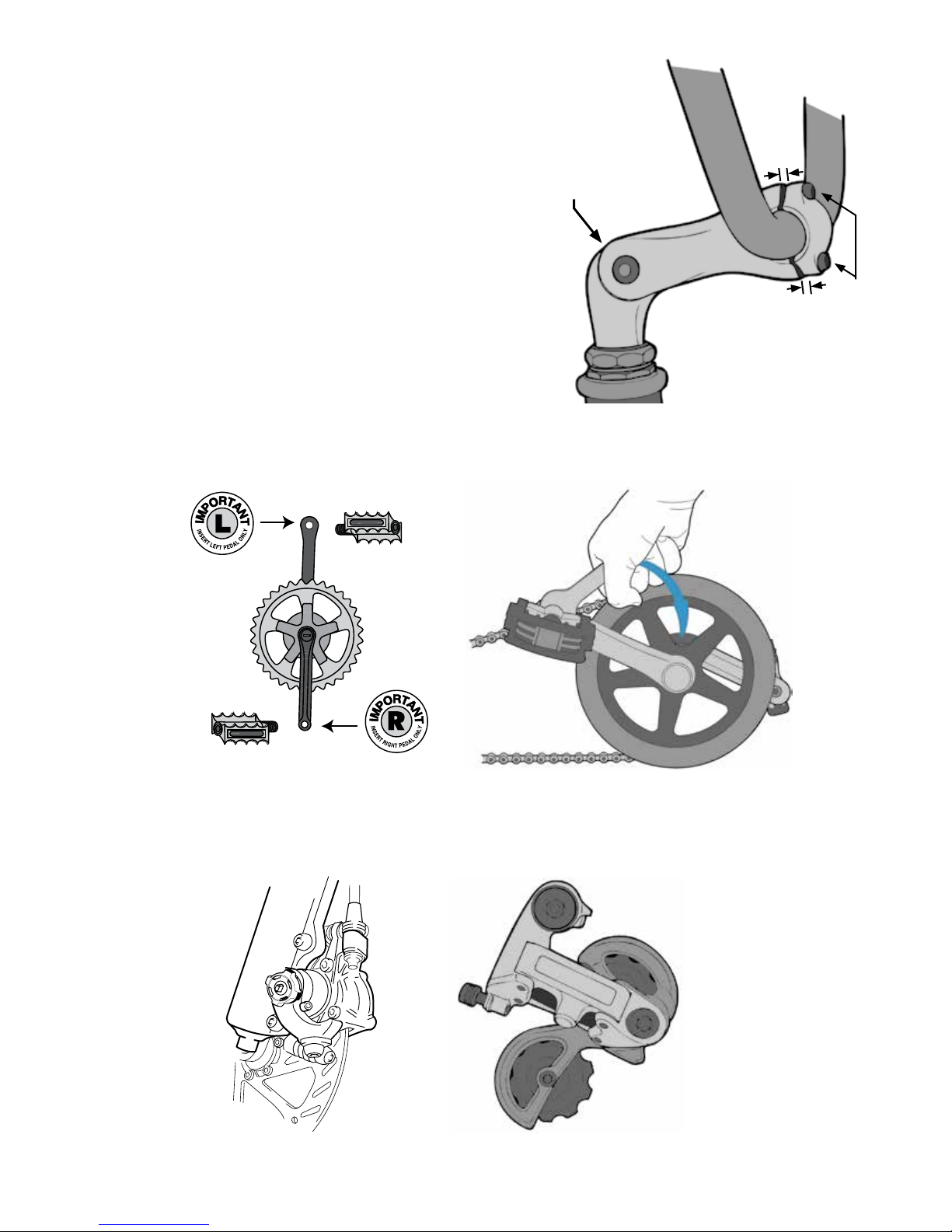
3. Find the stem in your parts box and slide it into the bicycle’s
head tube. Align the stem to be parallel with the front wheel,
then tighten the stem wedge bolt to the torque value listed in your
manual.
4. Clamp the handlebars into the stem. Make sure that the
handlebars are centered in the clamp; are aligned to a position that
you can comfortably reach the brakes from; that the wires and cables
running from the handlebar mounted components are not pinched,
crimped, or tangled; and that the stem’s faceplate bolts are properly
torqued.
Wedge bolt
(top)
5. Re-check your work. Make sure that the stem and handlebars
are properly aligned with respect to the bike’s front wheel, and that
the wedge bolt and faceplate bolts are properly torqued. Leaving the
wedge bolt too loose can result in the handlebars suddenly turning
Handlebars properly clamped in
stem. Note that the faceplate sits
evenly over the stem body.
Faceplate
bolts
away from the wheel as you ride. Further instructions can be found on
page 60 of your owner’s manual.
6. Install the pedals. Note that the left-side pedal is reverse threaded (left-hand); it needs to be tightened counterclockwise. Be sure to grease the pedal threads. See the torque values chart and page 65 of your owner’s manual (Pedals
and crank set) for detailed instructions.
7. Adjust your brakes and derailler(s). For detailed brake setup instructions, see pages 74-81 in your owner’s
manual. For derailleur setup instructions, please reference pages 82 and 83.
E3Metro Assembly Guide 2013
OM references to r71
April 4, 2013 12:17 PM
Page 3

8. Before your rst ride:
• Familiarize yourself with the operation of your bicycle’s electrical system (below).
• Be sure your tires are inated to the pressure indicated on the sidewall.
• Double-check the tightness of all nuts, bolts, quick release levers, and components.
• Check your brakes.
• Read the battery care guide on pages 42-43 of your owner’s manual.
Operation
Your IZIP electric bicycle features two operating modes:
1. Power-On-Demand Mode (POD)
2. Pedal Assist Mode (PAS)
In Power-On-Demand Mode (POD), motor power is regulated by actuation of the twist-grip throttle mounted on the righthand side of the handlebar. Twist the throttle toward you to apply motor power. Pedaling is optional. Power is available
whether you pedal or not. The position of the throttle will determine how much power is applied. To terminate power,
release the throttle allowing it to return to its “OFF” position.
In Pedal Assist Mode (PAS), the motor will assist you as soon as you begin pedaling the bike. The proportion of the
‘Assist’ is set via the display (see the following pages). If the rider does not pedal, no power is sent to the motor.
Ceasing pedaling during the ride will cause the motor to turn off. Motor power will be restarted when the rider begins
pedaling again.
While in Pedal Assist Mode (PAS), you can override the PAS function with the throttle. After beginning to ride, rotate the
throttle toward you to choose any percentage of motor power up to 100%.
Currie Technologies
®
Technical and Customer Service 1-800-377-4532
E3Metro Assembly Guide 2013
OM references to r71
April 4, 2013 12:17 PM
Page 4
Display operation
Your IZIP E3Metro electric bicycle is equipped with a multi-function display. The display is your user interface to the bike.
Using the display, you can program the riding characteristics of the bike, monitor the system self-tests as they occur,
and note any system errors. The display also serves as a cycle computer, giving information regarding time, speed and
distance.
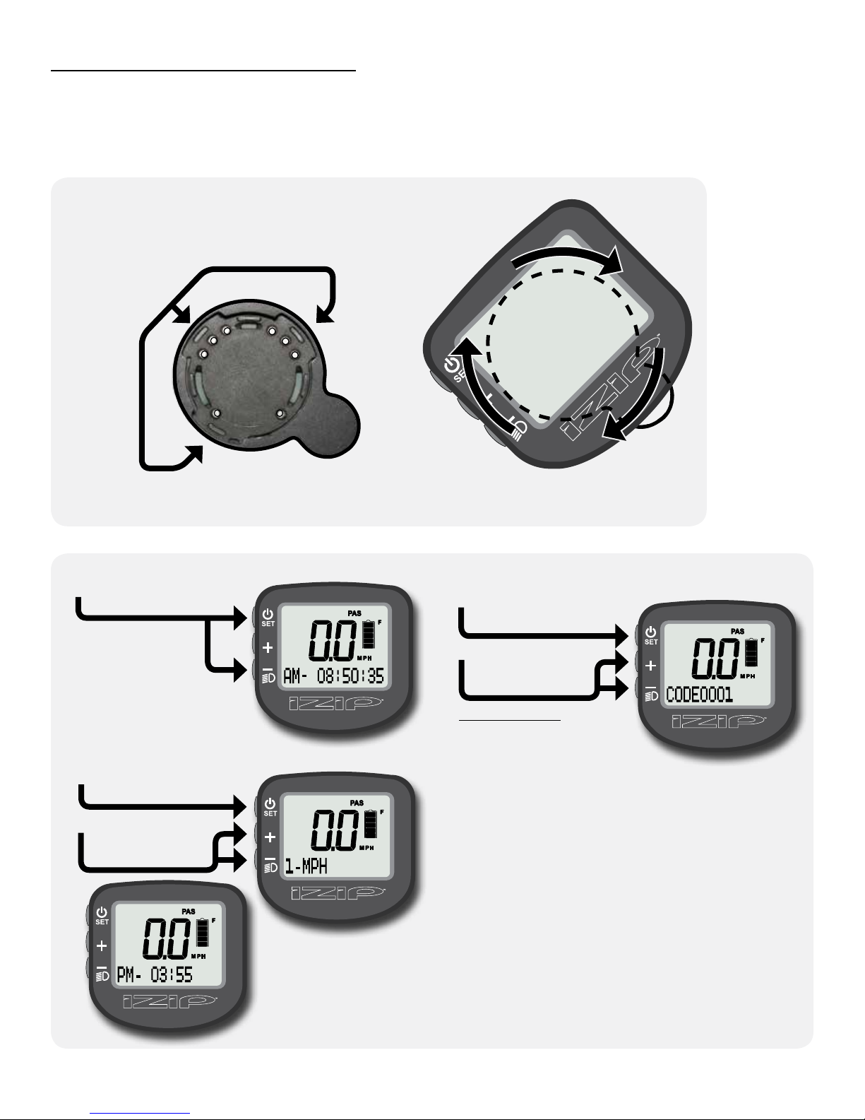
Connecting the display
Place the display on the handlebar
1
display mount at a 45° angle,
aligning the tabs on the bottom of
the display with the slots on the face
of the mount.
While pushing down
2
on the display, rotate
it 45° clockwise until
it stops, parallel with
the handlebars.
Sit on the bike, then turn it on by pressing the SET button.
3
Setting the clock and speed units
Hold SET and “–”
together for 5 seconds
to enter setup mode.
In setup mode, you
will enter codes
corresponding to
the setting you
wish to change.
In the setting screen,
3
tap SET to cycle
between characters.
Tap “+” or “–” to
change the ashing
character.
Tap SET to cycle
21
between digits. Hold
to conrm after the
code is entered.
Tap “+” or “–” to
set each digit
in the code.
Codes:
Set clock: 0001
Set speed units: 0003
Please do not experiment with undocumented codes.
While other settings exist, using them may cause the
bike to become unsafe to ride or to stop functioning
altogether.
Hold SET to conrm
4
your changes.
Hold SET and “–”
together to exit the
code screen and save
the changes.
E3Metro Assembly Guide 2013
OM references to r71
April 4, 2013 12:17 PM
Page 5
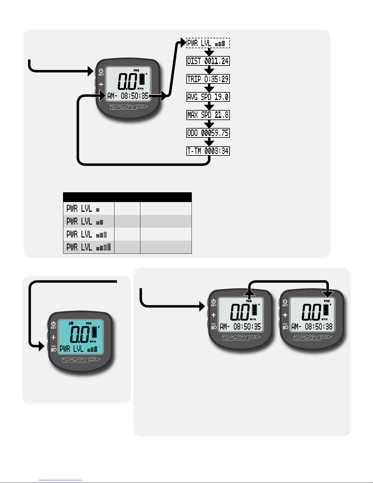
Using the display functions
Tap SET to cycle
between functions.
To reset all trip data, hold “+” and “–” together for 3 seconds.
Power levels
Displayed Level Motor output
Available in PAS mode only; sets
the strength of motor assist.
Displays the distance traveled
on this trip.
Displays the ride time for this
trip.
Displays the average speed for
this trip.
Displays the maximum speed
recorded on this trip.
Odometer; displays the bicycle’s
total mileage.
Displays the total ride time for
the bicycle.
Turning on the headlight
and LCD backlight
Hold “–” for 3 seconds to turn on
the LCD backlight and the bicycle
headlight/taillight (if present).
The backlight will not function
unless the display is mounted on
the bike (with a battery installed).
1
2
3
4
40%
60%
80%
100%
Changing the assist mode
Hold “+” for 3
seconds to change
from PAS to POD.
In PAS mode, the
motor will activate when
the system senses the
rider pedaling.
Use the “PWR LVL”
display function to
choose between light
assist, medium assist, and strong assist.
The throttle acts like a “boost”, allowing full control over 0-100% of motor
power at any time, regardless of power level.
In POD mode, only the throttle controls motor speed. There is no power
level setting in this mode, as the throttle can always apply 0-100% of motor
power. The torque sensor is disabled, and there is no need to pedal.
E3Metro Assembly Guide 2013
OM references to r71
April 4, 2013 12:17 PM
Page 6
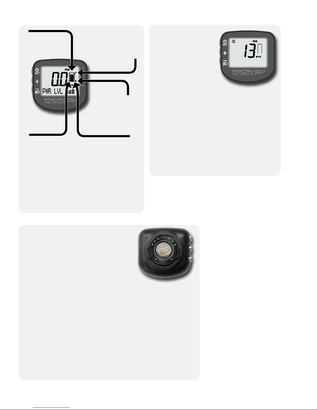
Understanding the battery gauge
Comm Error
Interpreting error messages
The cell diagram
indicates the charge
level of the main
battery.
“F” Illuminates
when the battery is
nearly full.
“E” Illuminates
when battery is
nearly empty.
The down arrow
Illuminates while
braking.
The up arrow
Illuminates while the
motor is being powered.
The gauge should show the battery level within a
few moments of turning on. Each “bar” represents
20% of the battery’s full charge.
If the gauge still shows completely empty after a
few seconds, check all connections to the controller and display, and re-connect.
You may also need to begin riding the bike before
the battery “wakes up” fully and begins sending
the charge signal to the display.
The IZIP display shows
coded error messages to
help diagnose problems
with the bike. These
messages appear
automatically if the system
senses an issue.
The most common error
message you may see
is Error 13: “Comm Error”. If this error comes up, it
means that the display is connected to the bike but
cannot communicate with the main controller (located
in the bike’s downtube).
Make sure the bike’s battery is installed and fully
charged. Check all connections between the display
and the controller, the battery and the controller, and
the display and its mounting bracket. Re-mount the
display, making sure it engages the mount fully.
If problems persist, or for information on other error
codes, please contact Currie Tech customer service.
Changing the display battery
The display can use power either from its
internal battery, or from the bike’s main
battery. The internal battery is used when the
display is disconnected from the bike, so you
can browse your ride data (like distance, time,
and average speed).
The display is powered by the bike’s battery
when connected to the bike. Even if the
internal battery in the display is dead or not
installed, the display will still operate using main battery power. However, if
you disconnect the display from the bike, it will immediately shut off.
The display uses one CR2032 3V watch battery. It should be available at
any store that sells electronics.
To replace, unscrew the display’s back cover using a coin. Remove the old
battery, then replace with a new one, oriented as shown (you should be
able to see the + symbol on the top of the cell). Replace the back cover,
tightening about 3/4 turn until snug.
After replacing the battery, you will need to re-set the clock. Trip time, trip
distance, average speed, and max speed will also be reset. The odometer
and total time values are stored in memory and will not be reset.
E3Metro Assembly Guide 2013
OM references to r71
April 4, 2013 12:17 PM
 Loading...