

Current Tools RotaBoom 77-22, RotaBoom 77SE-22, RotaBoom 77SR-22, RotaBoom 700SP, RotaBoom 700SI Operating, Maintenance, Safety And Parts Manual
Page 1

Current Tools™ 77 Series Electric Bender – 220 Volt
with Single Shoe Groups
for bending 1/2" thru 2" RIGID - EMT - IMC
and 40 mil PVC coated RIGID Conduit
50
130
140
Operating, Maintenance, Safety
This manual is free of charge. All personnel who operate this Bender
should have a copy of this manual and read and understand its
contents. To request a copy, call or write to the address below.
CURRENT TOOLS • P. O. BOX 17026 GREENVILLE, SC 29606
800.230.5421 or 864.721.4230 • FAX 864.721.4232
and Parts Manual
06/17
Read and understand this material before
operating or servicing this Bender. Failure to
understand how to safely operate and service
this unit may result in serious injury or death.
www.currenttools.com
Page 2

TABLE OF CONTENTS
Safety Alerts ....................................................................................3
Important Safety Information ....................................................4, 5
Specifications – 77 Series Electric Bender – 220 Volt ................. 6
Model Descriptions ........................................................................ 6
Features ........................................................................................6, 7
Shoe Groups ................................................................................... 8
Conduit Centerline Bending Radii ................................................ 8
Grounding Instructions .................................................................. 9
Mounting Bending Shoes .............................................................10
Mounting Roller Supports ............................................................ 11
General Bending Instructions ................................................12, 13
Bending Instructions for
1
1
⁄2" and 2" EMT & IMC Conduit ......................................... 14-16
Squeeze Adjustment Procedure for
1
1
⁄2" and 2" EMT & IMC Roller Supports ..................................17
Maintenance ............................................................................18, 19
Stub-Up Bending Information and Charts ............................20, 21
Offset Bending Information and Charts ................................22, 23
Troubleshooting ........................................................................... 24
Exploded Views .......................................................................25, 26
Parts List ..................................................................................27, 28
Electrical System Diagram ...........................................................29
Parts List – Bending Shoes & Roller Supports .................... 30-35
2
Page 3

jury
.
G
jury
.
ON
jury
.
G
R
SAFETY ALERTS
THIS SAFETY SYMBOL is used to call your attention to instructions
that concern your personal safety. It means: ATTENTION! BE AWARE!
THIS IS AN IMPORTANT SAFETY INSTRUCTION!
Read, understand, and follow these safety instructions. Failure to follow
these safety instructions may result in injury or death.
Safety Alert
Symbol
DAN
Immediate hazards which, if not avoided, WILL result in serious personal
or death
in
E
ARNIN
Hazards or unsafe practices which, if not avoided, COULD result in serious
personal in
or death
UTI
Hazards or unsafe practices which, if not avoided, COULD result in minor
personal in
or property damage
3
Page 4

RETAIN SAFETY INFORMATION
DANGER
DANGER
WARNING
DANGER
WARNING
DANGER
WARNING
DANGER
WARNING
DANGER
WARNING
DANGER
WARNING
DANGER
WARNING
DANGER
WARNING
DANGER
WARNING
DANGER
WARNING
DANGER
WARNING
DANGER
WARNING
DANGER
WARNING
DANGER
This manual should be read and understood by all personnel who operate
or service this bender. Failure to understand how to safely operate and
service this unit could result in injury or death. This unit should only be
operated and serviced by qualified personnel.
IMPORTANT SAFETY INFORMATION
NEVER operate the bender in an explosive atmosphere.
NEVER operate the bender in wet or damp locations.
DO NOT expose the bender to rain.
ALWAYS connect to a power supply that is properly installed and
meets all applicable electrical codes. See grounding instructions
on page 9.
ALWAYS inspect power cord before using bender.
Replace damaged or worn cords.
DO NOT modify the plug provided with the bender.
ALWAYS disconnect power to the bender before servicing.
ALWAYS make sure the circuit breaker switch is in the OFF
position before plugging in. This will reduce the risk of
unintentional starting.
ALWAYS use three-wire, 12 AWG extension cords that have
three-prong grounding type plugs and three hole receptacles
that accept the bender's plug.
NEVER use an extension cord longer than 100 feet.
ALWAYS replace damaged extension cords.
ALWAYS disconnect power to the bender before servicing or
changing shoes, attachments or roller supports, and when not in
use.
ALWAYS inspect the bender before operating. Replace any
damaged, missing or worn parts.
NEVER alter this equipment. Doing so will void the warranty.
NEVER remove guards, they are installed for your protection.
ALWAYS check for damaged or worn parts. Check for alignment
of moving parts, binding of moving parts, breakage of parts,
mounting and any other conditions that may affect its
operation. A guard or other part that is damaged should be
properly repaired or replaced.
4
4
Page 5

IMPORTANT SAFETY INFORMATION — continued
DANGER
DANGER
DANGER
DANGER
DANGER
DANGER
DANGER
DANGER
DANGER
DANGER
DANGER
DANGER
WARNING
DANGER
WARNING
DANGER
WARNING
DANGER
WARNING
DANGER
DANGER
DANGER
WARNING
WARNING
WARNING
WARNING
WARNING
WARNING
WARNING
WARNING
ALWAYS use recommended accessories. Consult this manual for
recommended accessories. The use of improper accessories may
cause risk of injury.
ALWAYS keep hands and feet away from pinch points such as
bending shoes, roller supports and conduit when bender is in use.
Operator must ALWAYS face the front of the bender with the
bending degree scale visible and maintain a minimum of 3 feet
distance from the bender while the conduit is being bent. All
other personnel must remain out of the area while the bender is
in operation.
ALWAYS use appropriate shoe groove and roller support for
the type and size conduit to be bent.
If bending shoe will not turn, STOP unit and unplug before
checking for any obstructions.
DO NOT use bender or attachments to do a job for which
it was not designed.
ALWAYS keep conduit under control when unloading.
ALWAYS keep the path of the bending conduit clear of
obstructions. Make sure all obstacles are clear of the bending
path BEFORE you bend the conduit.
WARNING
WARNING
WARNING
WARNING
WARNING
WARNING
CAUTION
CAUTION
CAUTION
Be sure handle is bolted securely to the bender frame before
moving or lifting the bender.
NEVER stand on bender. Serious injury could occur if the bender
is tipped or if the bending shoe is unintentionally contacted.
ALWAYS wear approved safety glasses when the bender is
in operation.
ALWAYS wear proper apparel. Do not wear loose clothing,
gloves, neckties, rings, bracelets, or other jewelry which may
get caught in moving parts. Non-slip footwear is recommended.
Wear protective hair covering to contain long hair.
ALWAYS keep children away. All visitors should be kept a safe
distance from work area.
ALWAYS make bender childproof with lockouts, master switches
or by unplugging unit.
The bender and some accessories exceed 50 lbs. and will
require more than one person to lift, transport and assemble.
Only use the bender for its intended purpose as specified
in this manual.
ALWAYS use this bender in a dry, well lighted area.
CAUTION
ALWAYS maintain bender with care. Keep bender clean for
best and safest performance.
5
Page 6

SPECIFICATIONS – 77 SERIES ELECTRIC BENDER
SPECIFICATIONS - 77 SERIES ELECTRIC BENDER WITH SINGLE SHOE GROUPS
1/2" thru 2" RIGID conduit
1/2" thru 2" EMT conduit
1/2" thru 2" IMC conduit
1/2" thru 2" 40 mil PVC coated RIGID conduit
1/2" thru 2" schedule 40 steel pipe
No modification to the
77-22 POWER UNIT is required
to accommodate these shoes
or roller supports.
No tools are required to
install or remove these
shoes and roller supports.
The 77 Series Electric Bender is NOT to be
used for bending any conduit or pipe wall thickness above schedule 40 pipe.
width 29 1/2"
length 24 3/4"
height 39"
weight 256 lbs. Power Unit Only - without shoes and roller supports
MODEL DESCRIPTIONS
Bender Power Unit and Bender Power Unit with Shoe Group
77-22 Electric Bender Power Unit only, without shoes and roller supports
77SR-22 Electric Bender with shoe and roller support for 1/2" thru 2" RIGID conduit
and schedule 40 pipe and 1/2" thru 1 1/4" IMC conduit
77SE-22 Electric Bender with shoe and roller support for 1/2" thru 2" EMT conduit
Shoe Group ONLY for use with 77-22 Power Unit
700SI 1/2" thru 2" IMC single shoe group for 77-22 power unit
700SP 1/2" thru 2" 40 MIL PVC Coated RIGID single shoe group for 77-22 power unit
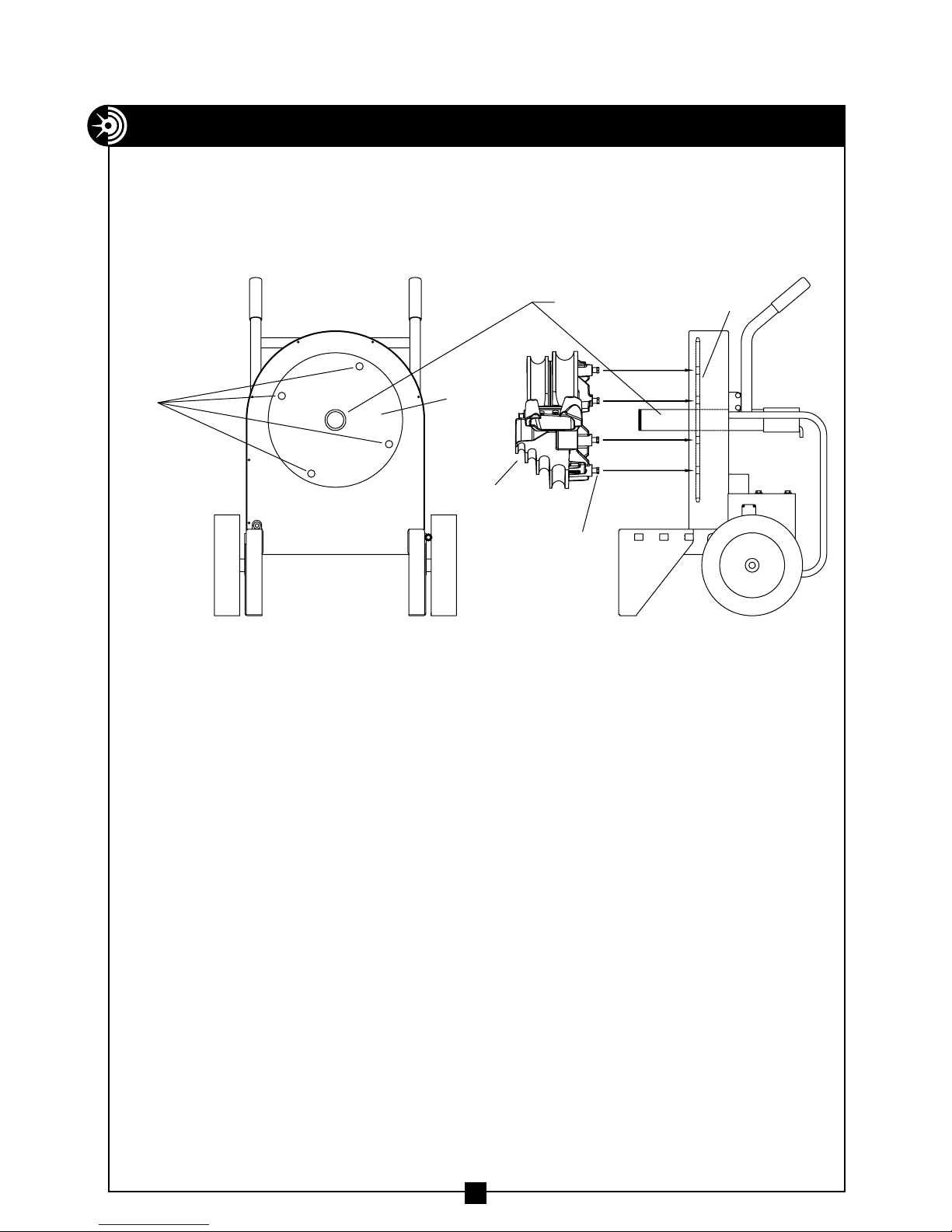
FEATURES
1. Bending Degree Scale - easy to read for exact bends.
2. Roller Supports - for supporting the conduit during bending.
3. Hinge Pin - for securing the roller supports.
4. 12 inch Wheels - for easy mobility.
5. D.C. Motor - quiet and strong.
6. Bending Instructions Decal -
easy to read for quick reference.
7. Remote Pendant - with 6 foot cord.
( Bend and unload from pendant. )
8. Removable Handle - may be
removed for dog-leg bends
9. Back Rails - Protect the back
of bender and enable the
bender to be used horizontally
1
50
2
8
6
9
130
140
5
4
7
3
6
Page 7

FEATURES — continued
y
.
G
REMOVE BOTH SCREWS
AND NUTS ON EACH SIDE
TO REMOVE HANDLE
Special Features
The 77 Series Electric Benders have a unique
feature to remove the handles during a
“Dog-Leg Bend." See Figure 7a below.
Figure 7a
ARNIN
When replacing handle, be sure to replace screws and nuts and also to tighten
securel
The 77 Series Electric Benders may also be used in a horizontal position
The bender can operate in this position as efficiently as it does in the upright
position. See Figure 7b below.
before moving or transporting
Figure 7b
7
Page 8

SINGLE SHOE GROUPS
RIGID
1
2
700SR - for bending 1/2" thru 2" RIGID conduit, 1/2" thru
1 1/4" IMC conduit and 1/2" thru 2" schedule 40 pipe
includes the following items.
Key Catalog# Description
1 2-3000 1/2" thru 2" bending shoe
2 2-4000 1/2" thru 2" roller support
3 8-0501 Storage box (not shown)
IMC
EMT
1
2
700SE - for bending 1/2" thru 2" EMT ( Thinwall )
includes the following items.
Key Catalog# Description
1 2-3100 1/2" thru 2" bending shoe
2 2-4200 1/2" thru 2" roller support
3 8-0501 storage box (not shown)
PVC COATED RIGID
1
1
2
700SP - for bending 1/2" thru 2" 40 mil PVC coated RIGID
700SI - for bending 1/2" thru 2" IMC conduit
includes the following items.
Key Catalog# Description
1 2-3000 1/2" thru 2" bending shoe
2 2-4100 1/2" thru 2" roller support
3 8-0501 storage box (not shown)
includes the following items.
Key Catalog Description
1 2-3200 1/2" thru 2" bending shoe
2 2-4300 1/2" thru 2" roller support
3 8-0501 storage box (not shown)
CONDUIT CENTERLINE BENDING RADII
size 1/2" 3/4" 1" 1 1/4" 1 1/2" 2"
EMT 4-5/16 5-1/2 7 8-13/16 8-3/8 9-1/4
IMC 4-1/4 5-7/16 6-15/16 8-3/4 8-1/4 9
RIGID 4-1/4 5-7/16 6-15/16 8-3/4 8-1/4 9
PVC COATED RIGID 4-1/4 5-7/16 6-15/16 8-3/4 8-1/4 9
2
8
Page 9

GROUNDING INSTRUCTIONS
RECEPTACLE PLUG
NEMA 6-15
WARNING
ELECTRIC SHOCK HAZARD! Only connect the bender to a 15 AMP GFCI
protected circuit. DO NOT modify the plug which is provided with the unit.
Failure to follow these warnings can result in serious injury or death.
Figure 9a Figure 9b
In the event of a malfunction or breakdown, grounding provides a path of least
resistance for electric current to reduce the risk of electric shock. The bender is
equipped with an electric cord having an equipment grounding conductor and a
grounding plug. Only connect the bender to a 15 AMP GFCI protected receptacle
which is properly installed and grounded to meet all applicable electrical codes.
Do NOT use an adapter.
Do NOT modify the plug provided. If it will not fit the receptacle, have the
proper receptacle installed by a qualified electrician.
Improper connection of the equipment grounding conductor can result in risk
of electric shock. The conductor with insulation having an outer surface that is
green with or without yellow stripes is the equipment grounding conductor. If
repair or replacement of the electric cord or plug is necessary, do not connect
the equipment grounding conductor to a live terminal.
Check with a qualified electrician or service personnel if the grounding
instructions are not completely understood, or if in doubt as to whether
the bender is properly grounded.
Use only 3-wire extension cords that have 3-prong grounding plugs and
3-pole receptacles that accept the bender’s plug.
Repair or replace damaged or worn cord immediately.
This bender is intended for use on a circuit that has a receptacle that looks
like the one illustrated in Figure 9a above. The bender has a grounding plug
that looks like the plug illustrated in Figure 9b above.
9
Page 10
MOUNTING BENDING SHOE
MAIN
DRIVE
HOLES
Choose the desired shoe (RIGID, IMC, EMT, or 40 mil PVC coated RIGID) and
slide shoe onto the main drive sprocket shaft. See Figure 10a below.
Note: Rigid and IMC conduit are bent on the same shoe. However, the roller
supports are specific for Rigid or IMC.
SPROCKET SHAFT
MAIN
DRIVE
SPROCKET
BENDING
SHOE
DRIVE
STUDS
Figure 10a Figure 10b
DRIVE
SPROCKET
Next, align the four drive studs on the back of the shoe with the four drive
holes in the main drive sprocket.
Push the shoe onto the main drive sprocket shaft. See Figure 10b.
10
Page 11

MOUNTING ROLLER SUPPORT
Choose the correct roller support for the
corresponding shoe and type conduit ( RIGID,
IMC, EMT, or 40 mil PVC coated RIGID ). The
appropriate size and type
of roller support MUST be used with the
corresponding shoe size and type.
Mount the roller support on the bender.
Secure the roller support with the quick
release hinge pin. See Figures 11a and 11b.
Figure 11a
Bender shown with
1/2" to 2" Rigid roller support
Figure 11b
Bender shown with
1/2" to 2" EMT roller support
MOUNTING INSTRUCTIONS FOR
GREENLEE® SHOES AND ATTACHMENTS
Most bending shoes and attachments for the Greenlee® 555® and 555 Classic® will
fit the Model #77-22 Bender. In addition, most bending shoes and attachments for
the Model #77-22 Bender will fit the Greenlee® 555® and 555 Classic® bender.
Contact Current Tools for specific applications and compatibility.
* Greenlee® 555® and 555 Classic® are registered trademarks of Greenlee/Textron.
11
Page 12

GENERAL BENDING INSTRUCTIONS
G
Bending instructions for:
1/2" thru 2" RIGID conduit
1/2" thru 1 1/4" EMT conduit
1/2" thru 1 1/4" IMC conduit
1/2" thru 2" 40 mil PVC coated RIGID conduit
1/2" thru 2" schedule 40 pipe
See pages 10 and 11 for mounting shoe and roller support.
Be sure to match the appropriate shoe with its corresponding roller support.
1. Mark pipe/conduit to the desired length. Note that a 2" minimum distance
from the end of the conduit to the bending mark is required to eliminate
flattening the end of the pipe/conduit. See Figure 12.
NOTE: Stub-up and Offset dimensions can be found on the bending charts
on pages 20 thru 23 of this manual or on the bending instruction decal on
top of each bender.
2. Rotate the bending shoe to 10 degrees below the 0 ( zero ) degree setting,
as shown in Figure 12 below.
DAN
operate this bender in an explosive atmosphere. Injury or Death may occur.
0°
-10°
BENDING
MARK
ER
Figure 12
MINIMUM
HOOK
2"
12
Page 13

GENERAL BENDING INSTRUCTIONS — continued
y
.
G
3. After marking the pipe/conduit, place it into the bender. See Figure 12.
The pipe/conduit should slide over the correct size roller support, through
the shoe groove and into the hook. The bending mark should be at the
front ( OUTSIDE ) edge of the hook. See Figure 12.
4. Using the remote pendant, place the “Bend/Unload" switch in the “bend"
position. Press the “Jog" button and advance the bender shoe. Be sure to
check the alignment of the bending mark as the rotating shoe locks the
pipe/conduit into position. Advance the bender shoe to the desired degree
of bend. When the arrow on the shoe reaches the desired degree of bend,
release the “Jog" button and the bender will stop.
NOTE: Due to springback in pipe/conduit, some over bending is
necessary to achieve the desired degree of bend. See page 21 or
the bending instruction decal on top of each bender for approximate
springback compensation figures.
5. To release the pipe/conduit, place the “Bend/Unload" switch in the
“Unload" position. Press the “Jog" button and reverse the shoe far
enough to release the conduit. Then, rotate the roller support out of
the way. See Figure 13a & 13b. The pipe/conduit can now be removed.
ARNIN
The pipe/conduit should be under control when unloading.
Failure to do this ma
result in injury or death
Figure 13a
Bender shown with
1/2" to 2" Rigid roller support
Figure 13b
Bender shown with
1/2" to 2" EMT roller support
13
Page 14

BENDING INSTRUCTIONS FOR
1 1/2" AND 2" EMT & IMC CONDUIT
1. See pages 10 and 11 for mounting shoe and roller support.
Be sure to match the appropriate shoe with its corresponding roller support.
NOTE: The frame color of the EMT roller support is silver (see Figure 14a).
The frame color of the IMC roller support is yellow (see Figure 14b).
SILVER YELLOW
EMT ROLLER SUPPORT IMC ROLLER SUPPORT
Figure 14a Figure 14b
2. Mark pipe/conduit to the desired length. Note that a 2" minimum distance
from the end of the conduit to the bending mark is required to eliminate
flattening the end of the pipe/conduit. See Figure 14c.
BENDING
MARK
HOOK
2"
MINIMUM
Figure 14c
NOTE: Stub-up and Offset dimensions can be found on the bending
charts on pages 20 thru 23 of this manual or on the bending instruction
decal located on the top of each bender.
14
Page 15

BENDING INSTRUCTIONS FOR
1 1/2" AND 2" EMT & IMC CONDUIT — continued
3. Rotate the bending shoe to 10 degrees below the 0 (zero) degree setting.
See Figure 12.
4. After marking the pipe/conduit, place it into the bender. The pipe/conduit
should slide over the roller support and through the shoe groove and into
the hook. The bending mark should be at the front ( OUTSIDE ) edge of
the hook. See Figure 14c.
NOTE: The appropriate size and type of roller support MUST be used
with the corresponding shoe size and type.
5. Step on the “Engaging Pedal" which will raise the rollers to come in
contact with the conduit. See Figure 15. Be sure the correct rollers for
the size conduit being bent are in position to engage the conduit.
NOTE: See SQUEEZE ADJUSTMENT PROCEDURE on page 17.
STOP
ENGAGING
PEDAL
ROLLERS SHOWN
IN RAISED (BENDING)
POSITION
Figure 15
15
Page 16

BENDING INSTRUCTIONS FOR
y
.
G
1 1/2" AND 2" EMT & IMC CONDUIT — continued
6. Keep foot pressure on the engaging pedal and push the “Bend/Unload”
switch to the “Bend” position. Then press the “Jog” button. The conduit
will pull the roller support against the stop. Foot pressure can then be
removed from the engaging pedal. Be sure to check the alignment of
the bending mark as the rotating shoe locks the conduit into position.
NOTE: If the roller support will not pull against the stop, the squeeze
adjustment is too tight and will need to be adjusted. See squeeze
adjustment procedure on page 17.
Advance the bender shoe to the desired degree of bend. When the pointer
on the shoe reaches the desired degree of bend, release the “Jog” button
and the bender will stop.
NOTE: Due to springback in pipe/conduit, some over bending is necessary
to achieve the desired degree of bend. See page 21 or the bending
instructions decal located on the top of each bender for approximate
springback compensation figures.
NOTE: DO NOT allow the rollers to come in contact with the bending
shoe. The shoe and rollers squeeze the conduit but they should never
touch each other.
7. To release the pipe/conduit, place the “Bend/Unload” switch in the “Unload”
position. Press the “Jog” button and reverse the shoe. The roller support
will then drop, allowing removal of the conduit.
ARNIN
The pipe/conduit should be under control when unloading.
Failure to do this ma
8. After removal of the conduit, inspect it for wrinkling or excessive side marks.
If these conditions occur, refer to the SQUEEZE ADJUSTMENT PROCEDURE.
See page 17.
result in injury or death
16
Page 17

SQUEEZE ADJUSTMENT PROCEDURE FOR
BO
MUST C
1 1/2" AND 2" EMT & IMC ROLLER SUPPORTS
The 1 1/2" and 2" rollers on the single shoe EMT Roller Support and the 1 1/2"
and 2" rollers on the single shoe IMC Roller Support on the 77 bender have a
Squeeze Adjustment feature if wrinkling or side marking becomes a problem
during the bending process. This feature allows you to increase or decrease
the amount of pressure applied to the conduit during bending, thereby eliminating these problems. Begin with the 7/8" starting location of the adjusting
bolts as shown in Figure 17a.
1. If wrinkling occurs, pressure against the conduit during the bending process
must increase. To increase the squeeze ( pressure ), loosen both set screws
and turn both adjusting bolts one-half turn clockwise. Bend one piece of
conduit to test the adjustment, and if wrinkling still occurs, repeat the
procedure. Once you have achieved a good bend, tighten both set screws.
NOTE: Both adjusting bolts MUST be in contact with the bender leg.
See Figure 17a.
STARTING LOCATION
OF ADJUSTING BOLT
7/8"
BENDER LEG
SET SCREW
ADJUSTING BOLT
Figure 17a
STOP
TH ADJUSTING BOLTS
ONTACT BENDER LEG
Figure 17b
2. If side marking occurs, pressure against the conduit during the bending
process must be decreased. To decrease the squeeze ( pressure ), loosen
both set screws and turn both adjusting bolts one-half turn counter-clock
wise. Bend one piece of conduit to test the adjustment, if side marking
still occurs, repeat the procedure. Once you have achieved a good bend,
tighten both set screws.
NOTE: Both adjusting bolts MUST be in contact with the bender leg. See
Figure 17a.
17
Page 18

MAINTENANCE
ALWAYS disconnect power supply before removing any guards or covers and
before servicing this bender. Failure to do so ma
y
result in serious injury or deat
h
ARNIN
G
1. The Gear Box is filled with oil at the factory and should not require periodic
flushing. If the Gear Box is opened for repair, flush by filling the unit with
an AGMA #7 oil. Next, run the unit with no load for 3 minutes. Then, drain
and refill the unit with 28 fluid ounces of an AGMA #7 oil such as the ones
listed below.
Amoco – Amoco Worm Gear Oil
Chevron – Cylinder Oil 460X
Exxon – CYLESSTIC TK460
Mobil – 600 W Cylinder Oil
Shell – Sun Gear Oil 7C
2. To inspect FRONT #60 chain tension:
• Remove front cover plate.
• To adjust, loosen hex bolt with 3/4 wrench and rotate chain tensioner
toward chain as shown until chain moves no more than a total of 1/4".
See Figure 18 below.
• Grease chain periodically with a good quality MP grease.
Figure 18
18
Page 19

WS
X SPROCKET
MAINTENANCE — continued
3. To inspect REAR #40 chain tension:
• Check chain tension after an initial break-in period of 2 - 3 hours of
use and tighten per the instructions below. See Figure 19.
Thereafter, inspect monthly.
• Remove the chain guard by taking out the 2 mounting screws.
• Loosen 8 bolts ( 4 on top and 4 on bottom ) that hold the gear box
in position.
• To tighten chain, move the gear box to the left and re-tighten bolts.
• For correct tension, chain should deflect approximately 1/8".
NOTE: Be sure to keep the gear box and motor in line with the bender.
• Grease chain periodically with a good quality MP grease.
4 BOLTS ON TOP
4 BOLTS ON BOTTOM
Figure 19
• Access to the gearbox sprocket
is possible by removing access
door as shown.
CHAIN GUARD
MOUNTING SCREWS
THIS COVER ALLO
ACCESS TO THE
GEARBO
IF ADJUSTMENT IS
NEEDED
19
Page 20

UB
H
G
UCT
H
GTH
UB
H
STUB-UP BENDING INFORMATION AND CHARTS — continued
PLA
IN LINE
EDGE OF SHOE HOOK
To locate bending marks and springback of 15, 30, 45, 60, and 90 degree
bends for a desired stub:
1. Check Chart A, B, C or C1 on Page 21 for deduct length. Note that minimum
stub length is deduct length plus 2".
2. Measure and mark desired stub length on conduit ( stub length mark ).
Subtract “Deduct Length" from this mark and make a second mark
( bending mark ). See Fig 20a and 20b. Place bending mark at front edge
of shoe hook. See Figure 20c. Check Chart A, B, C or C1 on Page 21 for
springback of desired degree of bend. Bender should be advanced to this
degree to obtain desired degree of bend.
Figure 20a
T
LENGT
Figure 20b
Figure 20c
BENDIN
LEN
TUB
DED
LENGT
T
LENGT
CE BENDING MARK
WITH FRONT
20
Page 21

STUB-UP BENDING INFORMATION AND CHARTS — continued
Chart A – RIGID Conduit/Schedule 40 Pipe
Conduit
Size
1/2" 7-1/2 17 33 49 64 96
3/4" 9 17 33 48 64 95
1" 11 17 32 48 63 94
1 1/4" 13-5/8 17 32 48 63 94
1 1/2" 14-7/8 17 32 48 63 94
2" 16-1/8 17 32 48 63 94
Deduct
Length
————— Springback —————
15° 30° 45° 60° 90°
Chart B – EMT Conduit
Conduit
Size
1/2" 7-1/2 16 32 48 63 95
3/4" 9 17 33 48 64 95
1" 11 17 32 48 63 94
1 1/4" 13-5/8 17 32 48 63 94
1 1/2" 14-7/8 19 35 50 66 97
2" 16-3/8 19 34 50 65 96
Deduct
Length
————— Springback —————
15° 30° 45° 60° 90°
Chart C – IMC Conduit
Conduit
Size
1/2" 7-1/2 20 36 51 67 98
3/4" 9 19 35 50 66 97
1" 11 19 35 50 66 97
1 1/4" 13-5/8 19 35 50 66 97
1 1/2" 14-7/8 17 33 49 64 96
2" 16-1/8 19 34 50 65 96
Deduct
Length
————— Springback —————
15° 30° 45° 60° 90°
Chart C1 – PVC Coated Rigid Conduit
Conduit
Size
1/2" 7-1/2 16 31 47 62 93
3/4" 9 15 31 46 62 93
1" 11 16 32 47 63 94
1 1/4" 13-5/8 15 30 46 61 92
1 1/2" 14-7/8 18 33 49 64 95
2" 16-1/8 19 34 50 65 96
NOTE: Springback figures are approximate.
Deduct
Length
————— Springback —————
15° 30° 45° 60° 90°
Minimum Stub Length = Deduct Length plus 2"
21
Page 22

END OF CONDUIT
TO START OF
BEND
ANGLE
OFFSET
HEIGHT
DEDUCT
LENGTH
MARK NO. 1
MARK NO. 3
CENTER TO CENTER
LENGTH
MARK NO. 2
OFFSET BENDING INFORMATION AND CHARTS
PLA
IN LINE
EDGE OF SHOE HOOK
To locate bending marks for a desired offset:
1. Measure distance from end of conduit to start of bend and mark conduit.
( Mark 1 ) See Figure 22a and 22b.
2. Refer to chart E for measurement “X" (see page 23) and deduct this
distance from Mark 1 and place Mark 2 on conduit. (See Figure 22b).
3. Refer to chart D (see page 23) for center-to-center distance between marks.
Measure this distance from Mark 2 and place Mark 3 on conduit.
4. Layout of bends is now complete. Next, place Mark 2 in line with front
edge of shoe hook and make first bend. (See Figure 22c).
5. Rotate conduit 180 degrees. Place Mark 3 in line with front edge of
shoe hook and complete second bend.
Figure 22a
Figure 22b
Figure 22c
CE BENDING MARK
WITH FRONT
22
Page 23

OFFSET BENDING INFORMATION AND CHARTS — continued
To locate center-to-center distance of offset bending marks other than those
listed in Chart D, use the following multipliers. Multiply the height of offset
desired by 3.86 on 15 degree bends, 2 on 30 degree bends, and 1.4 on 45
degree bends.
Chart E
Conduit Size
Figures are approximate.
1/2 3/4 1 1 1/4 1 1/2 2
“x” 3 1/16" 3 1/16" 3 3/16" 4" 4 1/4" 4 1/2"
23
Page 24

TROUBLESHOOTING
ALWAYS disconnect power supply before removing any guards or covers and
before servicing this bender. Failure to do so ma
y
result in serious injury or death
.
ARNIN
G
Problem Cause Diagnosis Cure
1. Bender will not operate Power source Check for voltage If power is on,
at power source go to ( #3 )
2. No power at bender Bad power cord Ohm cord for Replace cord
broken wire
3. Power to bender but Circuit breaker / Check power on Turn circuit
will not operate power switch in load side of breaker breaker on.
the off position to neutral with If on, go to
volt meter next step.
Fuse #1 blown Ohm circuit for short Replace
Control Transformer Check voltage in and out, Replace
bad if input but no output
Contactor bad Check contacts and ohm Replace
coil for open circuit
Bridge rectifier bad Check with Replace
ohm meter
Switch bad Check with ohm meter Replace
Motor bad Check brushes and ohm Replace
for open or short
armature
4. Motor runs but Chain from gear box Remove cover and Replace
will not bend to jack shaft broken visually check for
broken parts
Bad gear box Motor running but no Replace
output through gear box
Chain from jack shaft Remove cover and Replace
to shoe sprocket broken visually check for
broken parts
Key between motor and Remove motor from Replace key
gear box missing gear box
5. Bender operates in Bad FWD / REV switch Ohm switch for open Replace
one direction only contact or shorted
contacts
Bad pendant cord Ohm for broken wire Replace
Bad contactor Check contacts and Replace
ohm coil for open circuit
6. Contactors chatter Low power to bender Check with amp meter Do not use
long drop cords
24
Page 25

EXPLODED VIEWS
35
39
40
GEARBOX
MOUNT (REF)
41
37
42
WITH
SUPPLIED
GEARBOX
refer to PARTS LIST on page 27
190
3
130
120
40
110
100
90
16
12
7
17
180
170
160
150
140
73
80
70
60
50
40
30
20
10
10
0
11
10
34
27
SEE SEPARATE
BREAKDOWN
38
WITH GEARBOX
SCREWS INCLUDED
(4) 3/8-16 HEX
15
47
21
45
13
76
5
71
25
14
1
68
,75
29
24
8
23
20
73
6
9
47
2
46
32
,75
26
28
25
43
15
9
31
8
16
19
19
67
30
17
18
33
25
Page 26

BREAKER
SWITCH
CIRCUIT
62
44 (7)
ELECTRICAL
PLATE
22
53
55
56
66
57
61
63
MOUNTING HOLES-BENDER FRAME
54
AC
+
AC
27
54
60
58
76(7),80
59
72
74
4
PENDANT
REMOTE
53
28
48
77
78
49
50
51
64
65
52
36
53
80
81
79
EXPLODED VIEWS — continued
26
Page 27

PARTS LIST — 77-22 SERIES ELECTRIC BENDER
ITEM # PART # QTY DESCRIPTION
1 ........... 77-375..........1 ..................FRAME
2 ........... 77-346..........1 ................. HANDLE
3 ...........77-004D .........1 ..................COVER
4 ........... 77-004 ..........12 ......SCREW - #8-32 X 1/2" THD CUTTER
5 ........... 77-343 ..........1 ............. SPROCKET SHAFT
6 ...........77-006A .........2 .......KEY - SQUARE, 1/4" X 3/4" LONG
7 ........... 77-007 ..........1 ........ RETAINING RING - EXT, 2 1/2"
8 ........... 77-008 ..........2 ......WASHER - PHENOLIC (JACKSHAFT)
9 ........... 77-009..........2 ............. SLEEVE BEARING
10........... 77-010..........1 ............. #60 MASTER LINK
11........... 77-011..........1 ................ #60 CHAIN
12........... 77-394..........1 ........ SPROCKET - MAIN DRIVE #60
13...........77-013B .........1 .........SLEEVE - PHENOLIC (LONG)
14........... 77-014..........1 .........WASHER - PHENOLIC (MAIN)
15........... 77-015..........2 .................. WHEEL
16........... 77-016..........2 .........PIN - COTTER, 3/16" X 1 1/4"
17........... 77-017..........2 .............WASHER - 3/4" USS
18........... 77-429..........1 ...................AXLE
19...........77-033A .........9 .......SCREW - HEX, 10 X 1/2, #2 TEKS
20........... 77-413..........1 .............CHAIN TENSIONER
21...........77-013A .........1 ........ SLEEVE - PHENOLIC (SHORT)
22...........453-16A .........2 ............. NUT - HEX #8 - 32
23........... 8092-2..........1 ..........SCREW - HEX 1/2 - 13 X 1"
24...........2-1301-4 .........4 ......NUT - HEX, 5/16 - 18 (NYLON INS.)
25..........77-002D1 ........4 .........SCREW - HEX 5/16 - 18 X 3/4
26........... 77-026..........1 ............COVER - ELECTRICAL
27........... 77-339..........1 ............ PLATE - ELECTRICAL
28...........77-028A .........2 ......... STRAIN RELIEF - PENDANT
29........... 77-028..........1 ........STRAIN RELIEF - POWER CORD
30........... 77-288..........1 ............SPROCKET - #40 B48
31........... 77-031..........1 ................CHAIN - #40
32........... 77-032..........1 .............MASTER LINK - #40
33........... 77-468..........1 ............COVER - REAR CHAIN
34..........9518SR-12 ........4 ..........NUT - HEX, 1/4-20 (LOCK)
35........... 77-237..........1 ............SPROCKET - #40 B13
36...........77-3-1A .........1 ..............PLUG - PLASTIC
37........... 77-037..........1 ................ GEAR BOX
38............504-1 ..........2 ...................GRIP
39.........77-039-220V .......1 .............MOTOR – 220 VOLT
40........... 77-040..........8 ......BOLT - FLANGE LOCK, 3/8 - 16 X 3/4
27
Page 28
PARTS LIST — continued
ITEM # PART # QTY DESCRIPTION
41........... 77-041..........2 ...........FITTING - 90° LIQUITITE
42...........77-042A .........1 .............. FLEX CONDUIT
43..........77-043-22 ........1 ....... DECAL - SAFETY INFORMATION
44...........77-004B .........7 ..... SCREW - #8 - 32 X 5/8" THD CUTTER
45..........77-22SNP ........1 .......... SERIAL NUMBER PLATE
46........... 77-046..........1 ......DECAL - BENDING INSTRUCTIONS
47........... 77-047..........2 ...........PIN - ROLLER SUPPORT
48........... 77-048..........1 ..............CONDULET - 1/2"
49........... 77-451..........1 ................. GASKET
50........... 77-128..........1 .........GUARD - PENDANT SWITCH
51........... 77-051..........1 ....... SWITCH - FORWARD / REVERSE
52........... 77-052..........1 ...............SWITCH - JOG
53........... 77-053..........3 ... SCREW - #8 - 32 X 3/8" PAN HEAD MACH.
54........... 77-054..........2 ...............CONTACTORS
55.........77-055-220V .......1 ......... TRANSFORMER - 24 VOLT
56.........77-056-220V .......1 ...................FUSE
57........... 77-057..........1 ............. TERMINAL BLOCK
58.........77-058-220V .......1 .................RESISTOR
59.........77-059-220V .......1 ...........VARISTOR WITH WIRES
60........... 77-060..........1 .............BRIDGE RECTIFIER
61........... 77-061..........2 ....SCREW - RD. HEAD MACH., #6 -32 X 3/8"
62.........77-062-220V .......1 .............CIRCUIT BREAKER
63........... 77-063..........1 ......... COVER - CIRCUIT BREAKER
64........... 77-064..........1 .............DECAL - PENDANT
65........... 77-065..........1 ..........FISH PAPER - INSULATING
66........... 77-066..........1 ...............FUSE HOLDER
67........... 77-067..........1 ..............RETAINING RING
68........... 450-20..........4 ..................SPACER
69.........77-068-220V .......1 .........CORD - POWER (not shown)
70...........77-048A .........1 ........CORD - PENDANT (not shown)
71........... 77-714..........1 .............. ACCESS COVER
72...........77-058A .........2 ...... BRACKET - RESISTOR (not shown)
73...........452-6A .........9 .........SCREW #8 X ½” SELF DRILL
74........... 77-387..........1 .........BRACKET – TRANSFORMER
75...........77-041A .........2 ..............NUT – 1/2" LOCK
76...........77-004A .........11 .....SCREW – #8 – 32 X 3/8" THD CUTTER
77........... 747-19..........1 .................MAGNET
78........... 451-22..........1 .....SCREW 10-32 X 3/8" RD HD SLOTTED
79........... 451-21..........1 ...... NUT HEX 10 - 32 (NYLON INSERT)
80........... 747-39..........1 .......WASHER, LOCK – #8 EXT. TOOTH
81........... 747-40..........2 ..... WASHER, LOCK – 15/32" INT. TOOTH
28
Page 29

ELECTRICAL SYSTEM DIAGRAM
29
Page 30

PARTS LIST — SINGLE SHOES & ROLLER SUPPORTS
2-3000 & 2-4000 Bending Shoe & Roller Support —
1/2" to 2" RIGID Conduit AND Schedule 40 pipe
1/2" to 1 1/4" IMC conduit
10
ITEM # PART # QTY DESCRIPTION
1 ..................2-1304 .................4 .................................................... DRIVE STUD
2 ................ 2-2301-2 ................3 .......................... SCREW, SHOULDER SOCKET – 3/4" × 1 1/2"
3 ..................2-2302 .................1 ........................................ HOOK, 1 1/2"–2" RIGID/IMC
4 .............. 2-3000-101 ..............1 ......................................... SHOE – 1/2"–2" RIGID/IMC
5 .............. 2-3000-102 .............2 ................................... POINTER — DEGREE INDICATOR
6 ..................2-3002 .................1 .......................................HOOK, 1/2"–1 1/4" RIGID/IMC
7 ....................99-8 ...................2 ............................... SCREW, SKT. HD. CAP — 1/4-20 × 1/2"
8 ...................99-59 ..................4 ............................. SCREW, SKT. HD. CAP — 3/8-16 × 1 1/4"
9 ................ 450-14G ................2 .............................................. WASHER, LOCK 1/4"
10 .................2-4000 .................1 ........... ROLLER SUPPORT – 1/2" TO 2" RIGID AND 1/2" TO 1 1/4" IMC
11 ............2-4000-107A ............1 ........................ROLLER SUPPORT ASSEMBLY – 1/2" TO 1 1/4"
12 ............. 2-4000-122 ..............1 ...................................................... HINGE PIN
13 ............. 2-4000-123 ..............1 .......................................... RETAINING RING – 7/16"
14 ............. 2-4000-125 ..............1 ......................... ROLLER SUPPORT ASSEMBLY – 1 1/2" TO 2"
15 ............. 2-4000-001 ..............4 ............................... COLLAR, 3/4" I.D. — 1 1/2"–2" ROLLER
16 ............2-4000-106A ............1 ........................... WELDMENT – 1 1/2"–2" ROLLER SUPPORT
17 ............. 2-4000-128 ..............1 ................................. PIN – 3/4" DIA. FOR 1 1/2" ROLLER
18 ............. 2-4000-126 ..............1 ........................................... ROLLER — 1 1/2" RIGID
19 ............. 2-4000-127 ..............1 .............................................. ROLLER — 2" RIGID
20 ............. 2-4000-115 ..............2 .................................... PIN — 3/4" DIA. FOR 2" ROLLER
30
Page 31

PARTS LIST — SINGLE SHOES & ROLLER SUPPORTS
2-3200 & 2-4300
Bending Shoe & Roller Support —
1/2" to 2" PVC Coated RIGID Conduit
10
ITEM # PART # QTY DESCRIPTION
1.......................2-1304 ..................... 4 ................................................ DRIVE STUD
2..................... 2-2301-2 .................... 3 ...................... SCREW, SHOULDER SOCKET — 3/4 × 1 1/2"
3.......................2-3203 ..................... 1 ............................ HOOK, 1 1/2"–2" PVC COATED RIGID
4................... 2-3200-101 .................. 1 ............................ SHOE — 1/2"–2" PVC COATED RIGID
5................... 2-3000-102 .................. 2 ............................... POINTER — DEGREE INDICATOR
6.......................2-3202 ..................... 1 ........................... HOOK, 1/2"–1 1/4" PVC COATED RIGID
7.........................99-8 ....................... 2 ...........................SCREW, SKT. HD. SKT. — 1/4-20 × 1/2"
8........................99-59 ...................... 4 ......................... SCREW, SKT. HD. CAP — 3/8-16 × 1 1/4"
9..................... 450-14G .................... 2 .......................................... WASHER, LOCK 1/4"
10......................2-4300 ..................... 1 ...............ROLLER SUPPORT — 1/2" TO 2" PVC COATED RIGID
11.................2-4000-107B................. 1 ....................ROLLER SUPPORT ASSEMBLY – 1/2" TO 1 1/4"
12.................. 2-4000-122 .................. 1 .................................................. HINGE PIN
13.................. 2-4000-123 .................. 1 ..................................... RETAINING RING — 7/16"
14.................. 2-4300-103 .................. 1 ..................... ROLLER SUPPORT ASSEMBLY – 1 1/2" TO 2"
15.................. 2-4000-001 .................. 4 ........................... COLLAR, 3/4" I.D. — 1 1/2"–2" ROLLER
16.................2-4000-106B................. 1 ...................... WELDMENT — 1 1/2"–2" ROLLER SUPPORT
17.................. 2-4000-128 .................. 1 .............................. PIN – 3/4" DIA. FOR 1 1/2" ROLLER
18.................... 2-1005A ....................1 ........................... ROLLER — 1 1/2" PVC COATED RIGID
19.................... 2-1005B ....................1 .............................. ROLLER — 2" PVC COATED RIGID
20.................. 2-4000-115 .................. 2 ................................ PIN — 3/4" DIA. FOR 2" ROLLER
31
Page 32

PARTS LIST — SINGLE SHOES & ROLLER SUPPORTS
2-3100
6 1
Bending Shoe
1/2" to 2" EMT Conduit
8
5
4
9
7
2
2
2
3
1
9
4
1
1
7
ITEM # PART # QTY DESCRIPTION
1 ................ 2-1304 ........................ 4 ................................... DRIVE STUD
2 ...............2-2301-2 ...................... 3 ....... SCREW, SHOULDER SOCKET — 3/4" × 1 1/2"
3 ................ 2-2303 ........................ 1 ............................ HOOK, 1 1/2"–2 EMT
4 .............2-3000-102 .................... 2 ................. POINTER — DEGREE INDICATOR
5 .............2-3100-101 .................... 1 ........................... SHOE — 1/2"–2" EMT
6 ................ 2-3102 ........................ 1 .......................... HOOK, 1/2"–1 1/4" EMT
7 .................. 99-8 .......................... 2 ............. SCREW, SKT. HD. CAP — 1/4-20 × 1/2"
8 ................. 99-59 ......................... 4 ............SCREW, SKT. HD. CAP — 3/8-16 × 1 1/4"
9 ............... 450-14G ...................... 2 ............................ WASHER, LOCK 1/4"
32
Page 33

PARTS LIST — SINGLE SHOES & ROLLER SUPPORTS
2-4200
Roller Support
1/2" to 2" EMT Conduit
1
20
7
19
11
4
6
21
13
14
17
2
15
17
12
ITEM # PART # QTY. DESCRIPTION
1 ..................2-1103 ................... 2 ................................ ROLLER - 1.5" EMT
2 ..................2-1108 ................... 1 .................................... SPACER TUBE
3 ..................2-1109 ................... 4 ............................... 3/4" RETAINER RING
4 ..................2-1111 ................... 1 .......................187" DIA. X 1.25 LG ROLL PIN
5 ..................2-1112 ................... 2 ............... 1/2-13 X .75 LG SET SCREW - CONE PT
6 ..................2-1116 ................... 2 .................................. ROLLER - 2" EMT
7 ..................2-1118 ................... 8 ............................ 7/16-14 X 1.00 LG FHCS
8 ............. 2-4000-107D .............. 1 ...................1/2" - 1.25" EMT ROLLER SUPPORT
9 .............. 2-4000-122 ............... 1 ................................ HINGE PIN, UPPER
10 ............. 2-4000-123 ............... 1 .............................. 7/16" RETAINER RING
11 ............ 2-4100-107D .............. 1 ..................... EMT ROLLER SUPPORT FRAME
12 ............. 2-4100-118 ............... 1 ........................... AXLE, ROLLER BRACKET
13 ............. 2-4100-119 ............... 2 ............................. BRACKET - 2" ROLLER
14 ............. 2-4100-121 ............... 1 ......................... SPRING CLIP, 2.00" ROLLER
15 ............. 2-4100-122 ............... 1 ......................... SPRING CLIP, 1.50" ROLLER
16 ............. 2-4100-123 ............... 2 ................... 3/4" DIA. PIN, 1.50" - 2.00" ROLLER
17 ............. 2-4100-124 ............... 2 ..........................................SPRING
18 ............... 2-4200-1 ................. 1 ............................. DECAL (NOT SHOWN)
19 ............. 2-4200-101 ............... 2 ....................... BRACKET, 1.50" EMT ROLLER
20 ................747-858 .................. 2 ................................. ROLLER PIN 1.50"
21 ................747-859 .................. 2 ................................. ROLLER PIN 2.00"
22 ................747-894 .................. 2 .............................. ROLLER - URETHANE
23 .................8092-2 ................... 2 ......... SCREW-HEX HEAD CAP GR5 ZINC (1/2-13 X 1)
33
Page 34

PARTS LIST — SINGLE SHOES & ROLLER SUPPORTS
2-3000
Bending Shoe
1/2" to 2" IMC Conduit
2
6
4
5
9
7
2
2
3
1
1
8
8
1
7
9
5
1
ITEM # PART # QTY DESCRIPTION
1 ................ 2-1304 ........................ 4 ................................... DRIVE STUD
2 ...............2-2301-2 ...................... 3 ....... SCREW, SHOULDER SOCKET — 3/4" × 1 1/2"
3 ................ 2-2302 ........................ 1 ....................... HOOK, 1 1/2"–2 RIGID/IMC
4 .............2-3000-101 .................... 1 .......................SHOE — 1/2"–2" RIGID/IMC
5 .............2-3000-102 .................... 2 ................. POINTER — DEGREE INDICATOR
6 ................ 2-3002 ........................ 1 ..................... HOOK, 1/2"–1 1/4" RIGID/IMC
7 .................. 99-8 .......................... 2 ............. SCREW, SKT. HD. CAP — 1/4-20 × 1/2"
8 ................. 99-59 ......................... 4 ........... SCREW, SKT. HD. CAP — 3/8–16 × 1 1/4"
9 ............... 450-14G ...................... 2 ............................ WASHER, LOCK 1/4"
34
Page 35

PARTS LIST — SINGLE SHOES & ROLLER SUPPORTS
2-4100
Roller Support —
1/2" to 2" IMC Conduit
6
20
5
17
15
12
3
19
13
7
21
14
16
19
1
ITEM # PART # QTY. DESCRIPTION
1 .................2-1108 ........................... 1 ........................................ SPACER TUBE
2 .................2-1109 ........................... 4 ...................................3/4" RETAINER RING
3 .................2-1111 ........................... 1 .......................... .187" DIA. X 1.25 LG ROLL PIN
4 .................2-1112 ........................... 2 ...................1/2-13 X .75 LG SET SCREW - CONE PT
5 .................2-1118 ........................... 8 ................................ 7/16-14 X 1.00 LG FHCS
6 .................2-1204 ........................... 2 .....................................1.50" IMC ROLLER
7 .................2-1205 ........................... 2 .....................................2.00" IMC ROLLER
8 ............2-4000-107C ...................... 1 ....................... .50" - 1.25" IMC ROLLER SUPPORT
9 ............. 2-4000-122 ........................ 1 .................................... HINGE PIN, UPPER
10 ............ 2-4000-123 ........................ 1 .................................. 7/16" RETAINER RING
11 .............. 2-4100-1 .......................... 1 ................................. DECAL (NOT SHOWN)
12 ...........2-4100-107C ...................... 1 ..........................IMC ROLLER SUPPORT FRAME
13 ............ 2-4100-118 ........................ 1 ............................... AXLE, ROLLER BRACKET
14 ............ 2-4100-119 ........................ 2 ............................... BRACKET, 2.00" ROLLER
15 ............ 2-4100-120 ........................ 2 ............................BRACKET, 1.50" IMC ROLLER
16 ............ 2-4100-121 ........................ 1 ............................. SPRING CLIP, 2.00" ROLLER
17 ............ 2-4100-122 ........................ 1 ............................. SPRING CLIP, 1.50" ROLLER
18 ............ 2-4100-123 ........................ 2 ............................... .75" PIN, FOR 2" ROLLER
19 ............ 2-4100-124 ........................ 2 ..............................................SPRING
20 ...............747-858 .......................... 2 ..................................... ROLLER PIN 1.50"
21 ...............747-859 .......................... 2 ..................................... ROLLER PIN 2.00"
22 ...............747-894 .......................... 2 ..................................ROLLER - URETHANE
23 ................8092-2 ........................... 2 .............SCREW-HEX HEAD CAP GR5 ZINC (1/2-13 X 1)
24 ............ 2-4100-126 ........................ 1 ............................ .75" PIN FOR 1 1/2" ROLLER
25 ............ 2-4000-001 ........................ 1 ...................................... .75" I.D. COLLAR
35
 Loading...