

Page 1
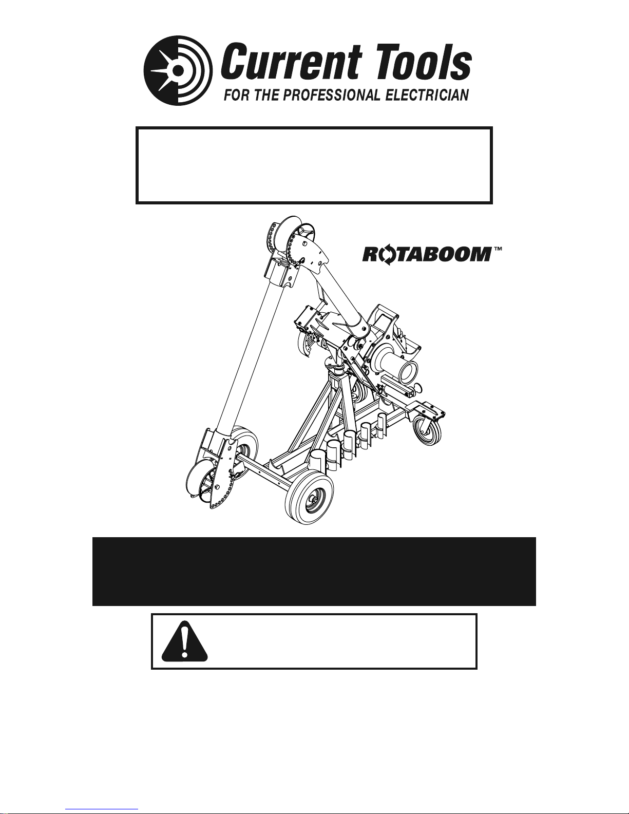
Current Tools™ Model #100
10,000 lb. Capacity
Mobile Cable Pulling Package
with Patented
Patent #9,899,811
Operating, Maintenance, Safety
This manual is free of charge. All personnel who operate the Cable Puller or any
component of the Cable Pulling Package should have a copy of this manual and read
and understand its contents. To request a copy of this manual or replacement safety
decals, or for technical assistance, call, write to the address below or visit our website.
CURRENT TOOLS • P. O. BOX 17026 GREENVILLE, SC 29606
800.230.5421 or 864-721-4230 • FAX 864-721-4232
and Parts Manual
7/2018
Read and understand this material before operating or
servicing the Cable Puller or any component of the Cable
Pulling Package. Failure to understand how to safely operate
and service these units may result in serious injury or death.
www.currenttools.com
Page 2
TABLE OF CONTENTS
Safety Alerts ..................................................................................... 3
Important Safety Information ..................................................... 4–7
Major Components .......................................................................... 8
Grounding Instructions ................................................................... 9
Assembly Instructions ..............................................................10-15
Common Set-Ups ........................................................................... 16
Transport Information .................................................................... 17
Floor/Chain Mount .................................................................... 18-22
Specifications and Features .....................................................23-24
MODEL 1450 CABLE PULLER
Cable Pulling Basics ........................................................... 25, 26
Operating Instructions ........................................................ 27-30
Maintenance ............................................................................. 31
Exploded Views and Parts Lists — Model 1450 ...............32-35
Wiring Diagram — Model 1450 ............................................... 36
Components Parts Listing .................................................. 37-41
2
Page 3
jury
.
G
jury
.
ON
jury
.
G
R
SAFETY ALERTS
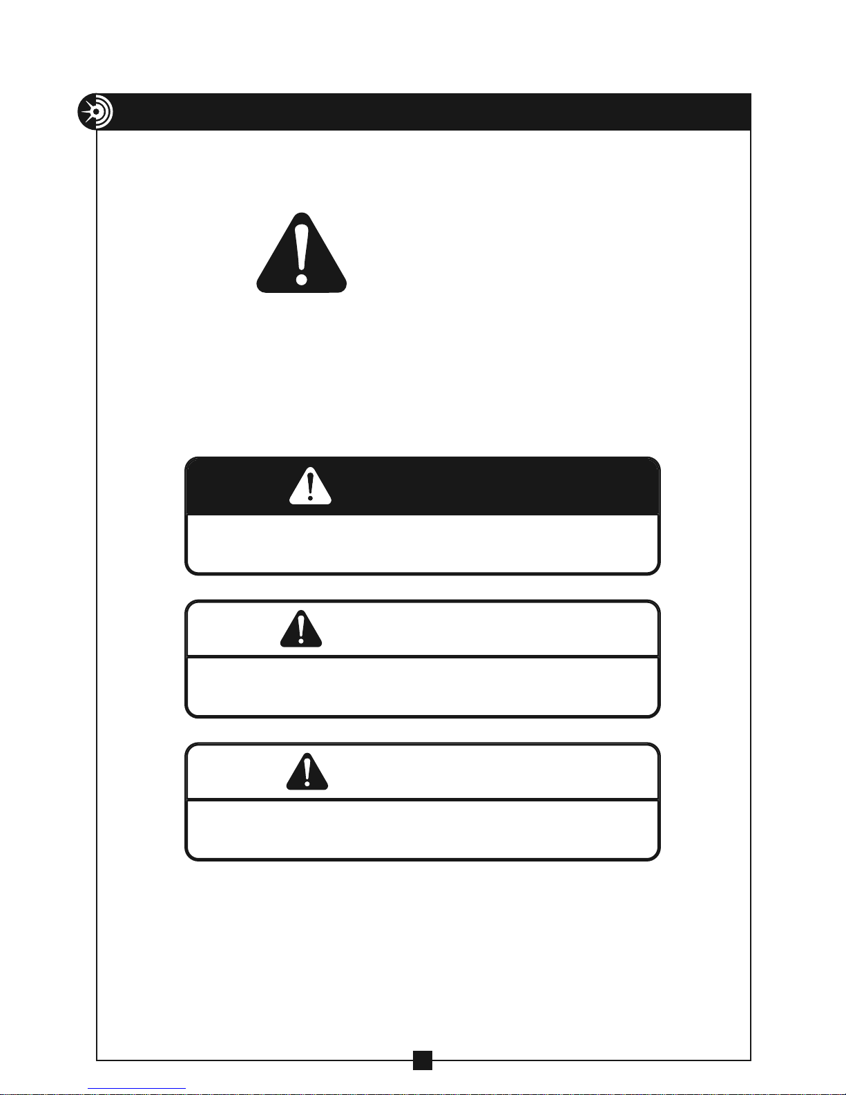
THIS SAFETY SYMBOL is used to call your attention to instructions
that concern your personal safety. It means: ATTENTION! BE AWARE!
THIS IS AN IMPORTANT SAFETY INSTRUCTION!
Read, understand, and follow these safety instructions. Failure to follow
these safety instructions may result in injury or death.
Safety Alert
Symbol
DAN
Immediate hazards which, if not avoided, WILL result in serious personal
or death
in
E
ARNIN
Hazards or unsafe practices which, if not avoided, COULD result in serious
personal in
or death
UTI
Hazards or unsafe practices which, if not avoided, COULD result in minor
personal in
or property damage
3
Page 4
RETAIN SAFETY INFORMATION
DANGER
WARNING
DANGER
DANGER
DANGER
WARNING
DANGER
DANGER
DANGER
WARNING
DANGER
WARNING
DANGER
This manual should be read and understood by all personnel who operate
or service this Puller. Failure to understand how to safely operate and
service this unit could result in serious injury or death. This unit should
only be operated and serviced by qualified personnel.
IMPORTANT SAFETY INFORMATION
DANGER
DANGER
DANGER
WARNING
WARNING
WARNING
WARNING
WARNING
DO NOT operate cable puller in wet or damp locations. DO NOT
expose to rain.
DO NOT operate in an explosive atmosphere.
DO NOT use cable puller as a hoist or for lifting, supporting or
transporting people or loads. Use only for its intended purpose as
a cable puller.
DO NOT wrap rope around any body parts. DO NOT wrap rope
around wrists.
ALWAYS keep rope away from operator’s feet.
DO NOT exceed load rating of cable puller, rope, or accessories.
ALWAYS inspect rope before each use.
ALWAYS disconnect cable puller before servicing.
ALWAYS plug the Model 1450 Cable Puller into a grounded
receptacle with a 20 amp GFCI protected circuit. DO NOT modify
the plug provided with the Model 1450 Cable Puller.
ALWAYS inspect the structural integrity of any supports, conduit,
anchoring system etc. that will hold the cable puller during the
pull. These supports should be able to withstand the maximum
pulling force of the cable puller plus a safety factor of 3:1.
Example: 10,000 lb. puller should be anchored to a support that
can withstand 30,000 lbs. of pull.
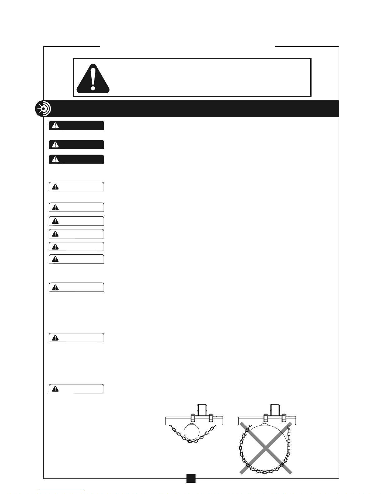
When using the Model #2280 floor mount or Model #2281 chain
mount, ALWAYS ensure the cable puller is properly pinned onto
the floor/chain mount and that the floor/chain mount is properly
secured before operating. ALWAYS attach the Model #2281 chain
mount to supports that are at least 2" and not more than 10" wide.
See Figure 4
DO NOT mount the Model #2281 floor/chain mount to square
columns or I-Beams. The mounting chains will not tighten properly
on these structures.
Figure 4
OK TOO WIDE
4
4
Page 5
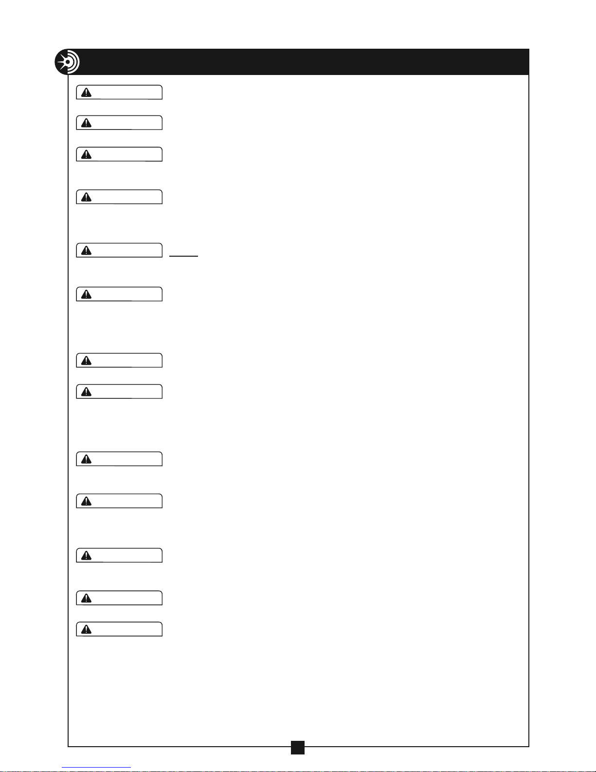
IMPORTANT SAFETY INFORMATION — CONTINUED
WARNING
DANGER
DANGER
DANGER
WARNING
DANGER
DANGER
WARNING
DANGER
WARNING
DANGER
DANGER
DANGER
DANGER
DANGER
WARNING
DANGER
WARNING
DANGER
Pulling Rope should be the only thing to contact the capstan.
NEVER let swivels, grips, etc. come in contact with the capstan.
WARNING
WARNING
WARNING
WARNING
Keep as much rope confined in conduit as possible. This will help
prevent injury should the rope break and whip violently.
Rope must ALWAYS be pulled over a rotating sheave. If a sheave
does not rotate, turn cable puller off immediately and determine
problem before continuing the pull.
This cable puller is equipped with an anti-reversing pawl. The pawl
will make a clicking sound when the capstan is rotating. If you can
not hear the clicking sound as the capstan rotates, immediately turn
the cable puller off and do not use until repaired.
ONLY use 7/8” diameter or larger double-braided composite pulling
rope, or a pulling rope with a minimum average breaking strength
of 32,000 lbs.
NEVER allow the rope to slip on a rotating capstan for more than
a couple of seconds. The rope will wear in that spot and the rope
could break under pressure. If you need to stop the pull, turn the
cable puller off and tie the rope off to hold it in place until you
restart your pull.
Keep all body parts, hair, loose clothing, etc. away from rotating
parts and pinch points. Keep hands away from capstan.
NEVER allow the rope to overlap on the capstan. If this condition
begins to occur, immediately release the tailing force on the rope so
that the rope can feed back toward the conduit or cable tray. If this
does not remedy the overlap, turn off the cable puller immediately.
There is no known solution for rope overlap.
WARNING
WARNING
WARNING
Some components of the mobile cable pulling package exceed 50
lbs. and will require more than one person to lift, transport and
assemble.
ALWAYS inspect pins to be sure they are the correct part number for
the assembly and are fully inserted through holes and have spring
clips property attached. DO NOT substitute any other object for
factory supplied pins.
The pulling rope must come in contact with ALL the sheaves used
in the boom system. This includes the elbow unit sheave when the
elbow unit is installed.
When making a vertical cable pull, keep the area underneath the
cable pull clear of all personnel.
ALWAYS ensure the factory supplied boom tubes are fully inserted
into the receiver tubes and that the spring loaded boom pins are
fully engaged in the boom tube holes. When using boom tubes
other than factory supplied, ensure they are fully inserted into the
receiver tubes (sight holes are provided to ensure tubes are fully
inserted) and 1/2-13 × 2" hex head cap screws (not provided) are
installed and tightened against the tubes. DO NOT transport the
puller on the carriage with boom tubes longer than the factory
supplied 3' and 4' tubes.
5
Page 6
IMPORTANT SAFETY INFORMATION — CONTINUED
WARNING
DANGER
WARNING
DANGER
WARNING
DANGER
WARNING
DANGER
WARNING
DANGER
WARNING
DANGER
DANGER
WARNING
DANGER
WARNING
DANGER
WARNING
DANGER
WARNING
CAUTION
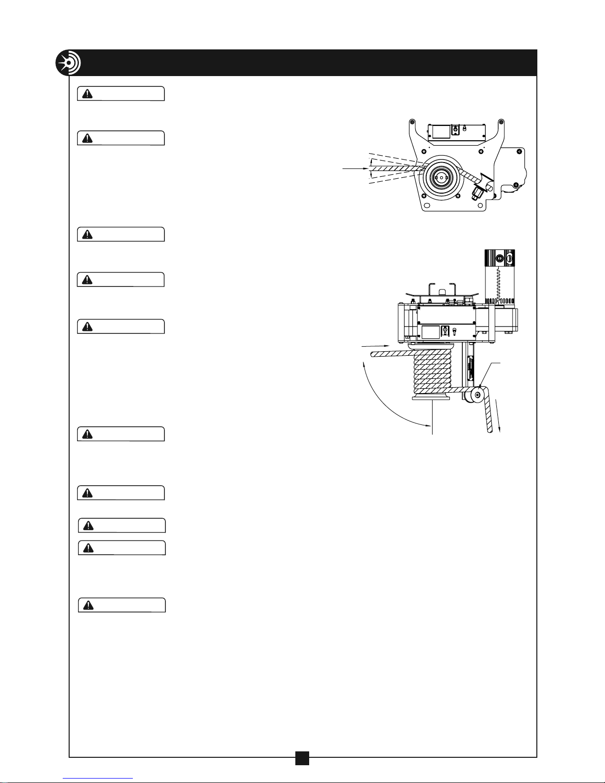
Rope should approach
capstan as shown in
Figure 6a
ALWAYS use black roller
to guide rope so that the
operator stands at a 90˚
angle to the cable puller
PULL
DIRECTION
and out of the direct line
of tight pulling rope. See
Figure 6b.
ALWAYS wrap rope beginning
at housing end of capstan as
shown in Figure 6b.
To help avoid rope overlap,
rope should approach capstan
at 90˚ angle. See figure 6b.
ALWAYS make sure the puller
motor has completely stopped
before switching from low
to high speed or high to low
speed. A puller ready light is
mounted in the electronics box
and will illuminate green when
the motor is ready for use.
MAXIMUM
10˚
MAXIMUM
10˚
PULL
DIRECTION
90˚
SIDE
VIEW
Figure 6a
OVERHEAD
VIEW
BLACK
ROLLER
CAUTION
CAUTION
CAUTION
CAUTION
CAUTION
DO NOT alter this cable puller.
Doing so will void the warranty.
Figure 6b
TO
OPERATOR
Guards and safety features are
provided for your protection.
DO NOT use an extension cord longer than 100 ft. Extension
cord should be a minimum of 12 gauge wire with ground.
Wear eye protection when operating cable puller.
Inspect all components of the pulling system before beginning
any cable pull. This includes the pulling system ( cable puller,
boom, etc. ) and any accessories ( sheaves, swivels, pins, etc. )
Replace any worn or defective components.
Be careful during assembly and disassembly of the boom
components. Keep pins in place to avoid uncontrolled
movement of boom components. Have control of boom
components before removing any pins.
6
Page 7
IMPORTANT SAFETY INFORMATION — CONTINUED
O
OK
OK
Hex Head Bolt
WARNING
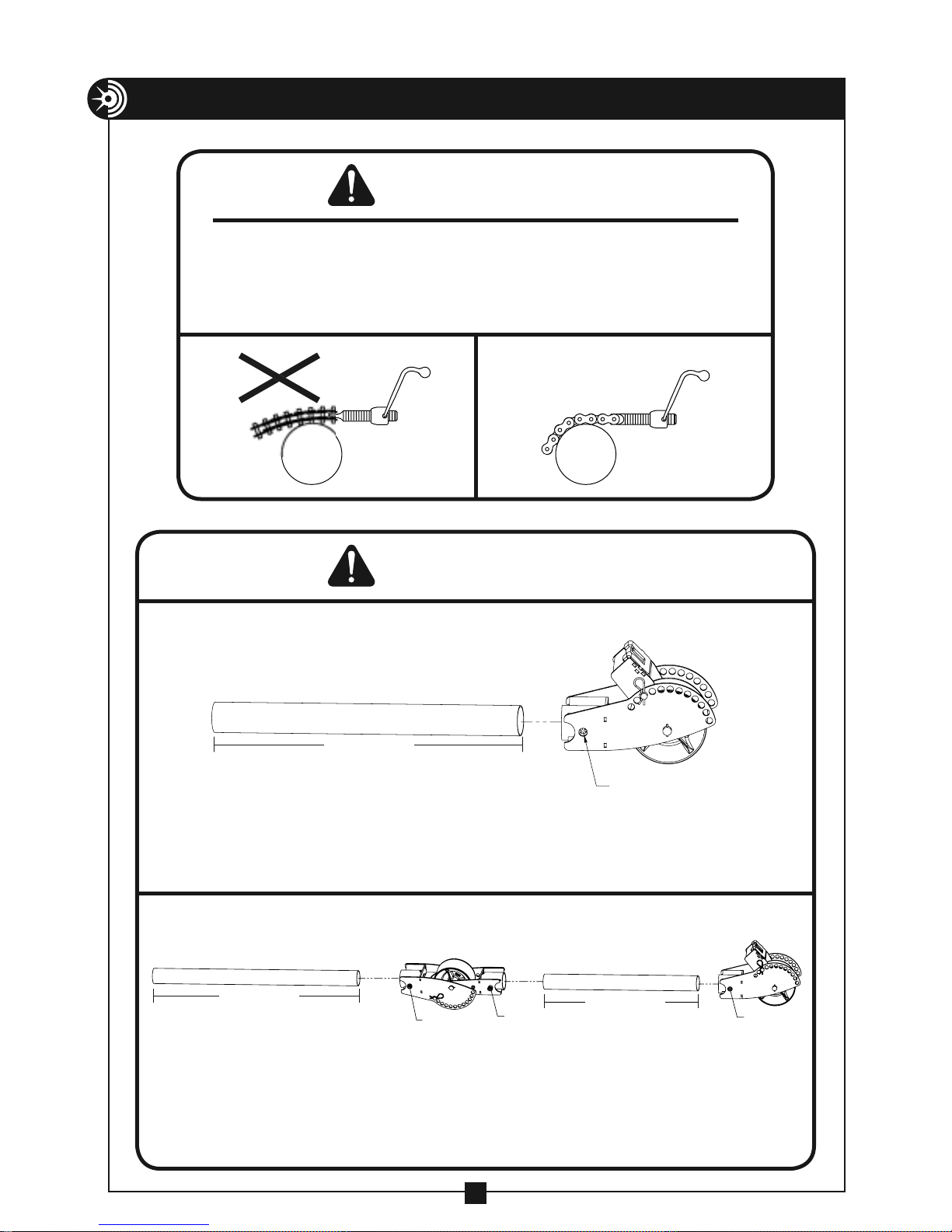
When using the Model #2281 chain mount, never tighten chain as shown in Figure
A. This causes side loading of the chain and can result in failure of the chain or
screw causing components to come loose and possibly cause serious injury or
death. Figure B shows the proper alignment of screw and chain for tightening.
N
Figure A Figure B
WARNING
When using one boom tube and nose unit, factory supplied boom tube may be replaced but
must meet the following specifications:
3' min. to 10' max.
• Only use 3" schedule 40 pipe or 3"
rigid conduit
• Check sight holes to be sure boom tubes
are fully inserted. Then tighten 1/2-13 × 2"
hex bolt (user provided).
• DO NOT transport the puller on the carriage
with boom tubes other than the factory
supplied 3' and 4' tubes.
When using elbow unit, nose unit and both boom tubes, factory supplied boom
tubes may be replaced but must meet the following specifications:
3' min. to 10' max.
1/2-13 × 2"
Hex Head Bolt
1/2-13 × 2"
Hex Head Bolt
1/2-13 × 2"
Hex Head Bolt
3' min. to 10' max.
1/2-13 × 2"
• Only use 3" schedule 40 pipe or 3"
rigid conduit
• Check sight holes to be sure boom tubes
are fully inserted. Then tighten 1/2-13 × 2"
hex bolt (user provided).
• DO NOT transport the puller on the
carriage with boom tubes other than the
factory supplied 3' and 4' tubes.
7
Page 8
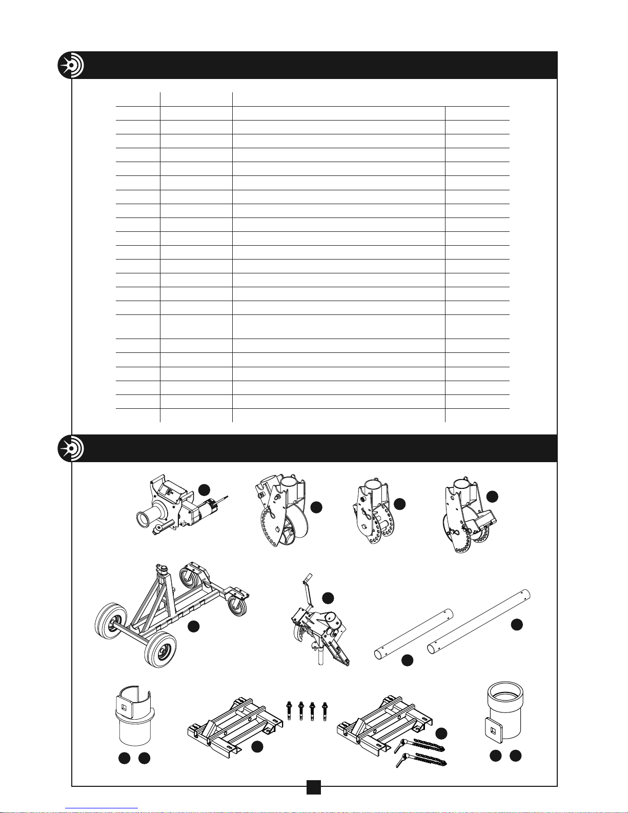
MAJOR COMPONENTS — MODEL #100
ITEM # CATALOG # DESCRIPTION WEIGHT
1 1450 Cable Puller – 10,000 lb Capacity 119 lbs.
2 1710 Elbow Unit 43 lbs.
3 1840 (optional) Nose Unit 33 lbs.
3A 1840-S Nose Unit with Sheave 34 lbs.
4 1000 Mobile Carriage 75 lbs.
5 1190 Puller Mount 89 lbs.
6 1850 Boom Tube – 36" Long 13 lbs.
7 1860 Boom Tube — 48" Long 17 lbs.
8 198 Coupling – 2" 1.6 lbs.
9
10 200 Coupling – 3" 2.4 lbs.
11 201 Coupling – 3 1/2" 3.8 lbs.
12
13
14
15
16
17
18
19
20
21
199 Coupling – 2 1/2" 1.9 lbs.
202 Coupling – 4" 4.3 lbs.
230 (optional) Coupling – 5" 4.8 lbs.
255 (optional) Coupling – 6" 5.5 lbs.
2280
(optional) Floor Mount and four 5/8" X 6"
wedge anchors
2281 (optional) Chain Mount with chains
259 (optional) Screw-on Coupling – 2"
260 (optional) Screw-on Coupling – 2 1/2"
261 (optional) Screw-on Coupling – 3"
262 (optional) Screw-on Coupling – 3 1/2"
263 (optional) Screw-on Coupling – 4"
40 lbs.
50
lbs.
2.1 lbs.
2.4 lbs.
2.9 lbs.
4.3 lbs.
4.8 lbs.
MAJOR COMPONENTS LIST — MODEL #100
8 14
–
1
2
5
4
15
(optional)
3
6
16
3A
17 21
–
7
8
Page 9
GROUNDING INSTRUCTIONS
PLUGREC
EPTACL
E
WARNING
ELECTRIC SHOCK HAZARD! Only connect the Model 1450 Puller to a 20 amp GFCI
protected circuit. DO NOT modify the plug that is provided with the unit. Failure to
follow these warnings can result in serious injury or death.
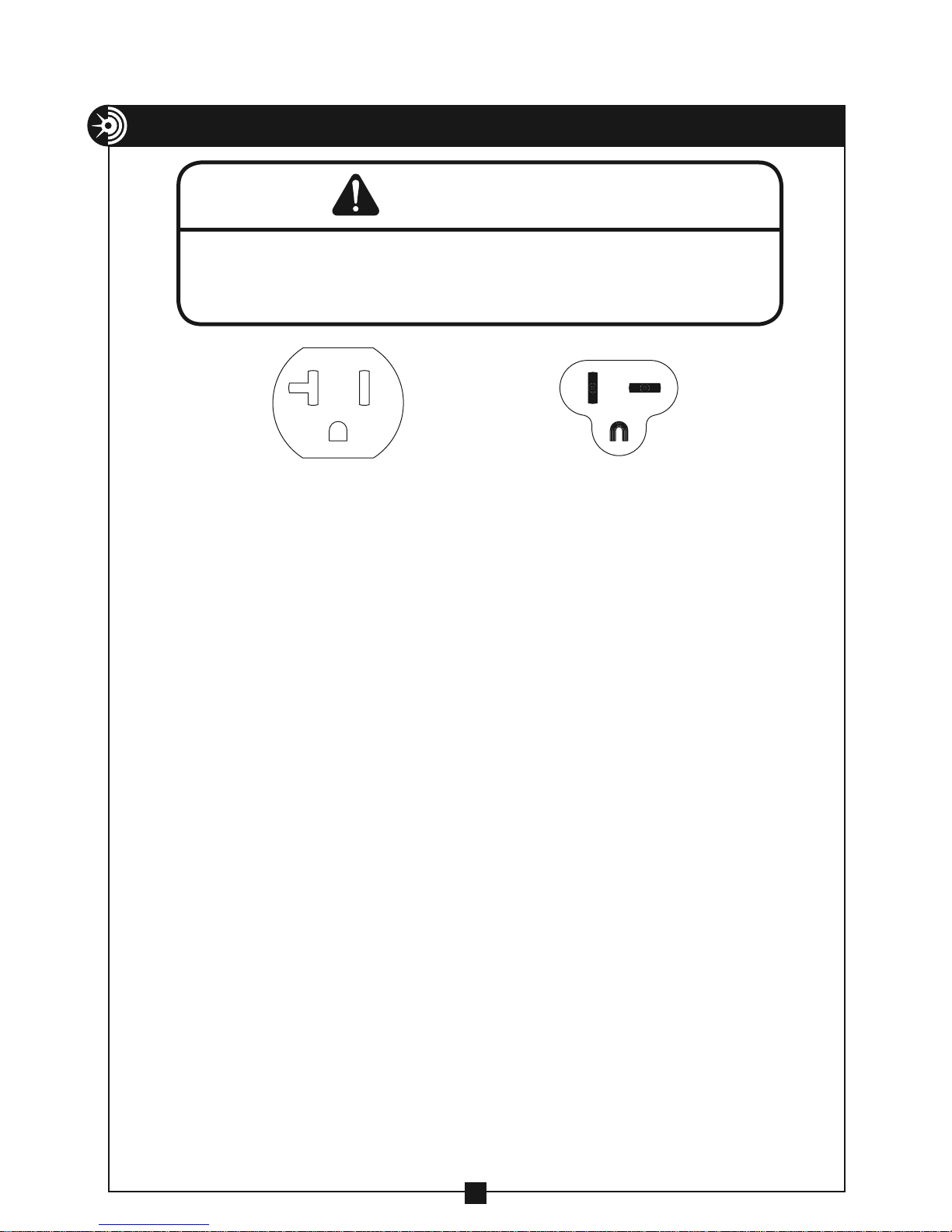
Figure 9 Figure 9A
In the event of a malfunction or breakdown, grounding provides a path of
least resistance for electric current to reduce the risk of electric shock. The
Model 1450 puller is equipped with an electric cord having an equipment
grounding conductor and a grounding plug. Only connect the Model 1450
puller to a 20 amp GFCI protected receptacle which is properly installed and
grounded to meet all applicable electrical codes. DO NOT use an adapter.
DO NOT modify the plug provided. If it will not fit the receptacle, have the
proper receptacle installed by a qualified electrician.
Improper connection of the equipment grounding conductor can result in risk
of electric shock. The conductor with insulation having an outer surface that
is green with or without yellow stripes is the equipment grounding conductor.
If repair or replacement of the electric cord or plug is necessary, do not connect the equipment grounding conductor to a live terminal.
Check with a qualified electrician or service personnel if the grounding
instructions are not completely understood, or if in doubt as to whether
the Model 1450 Puller is properly grounded.
Use only 3-wire extension cords that have 3-prong grounding plugs and
3-pole receptacles that accept the Model 1450 puller's plug.
Repair or replace damaged or worn cord immediately.
This puller is intended for use on a circuit that has a receptacle that looks like
the one illustrated in Figure 9 above. The puller has a grounding plug that
looks like the plug illustrated in Figure 9A above.
9
Page 10
ASSEMBLY INSTRUCTIONS
Planning the Pull
WARNING
Some components weigh more than 50 lbs. and will require more than one
person to lift, transport and assemble.
1. Referring to the major components list on page 8 make sure you have all
the components necessary to build a complete package.
2. Plan the pull to determine which components you will need.
Coupling Selection
The nose unit of the puller package is connected to the conduit using Current
Tools slip-in couplings or optional screw on couplings. From the information
in this section, choose and install a coupling that will meet your pulling
requirements.
Slip-In Couplings
Slip-In Couplings are provided for conduit sizes 2", 2 1/2", 3", 3 1/2" and 4".
5" and 6" couplings are available as an option.
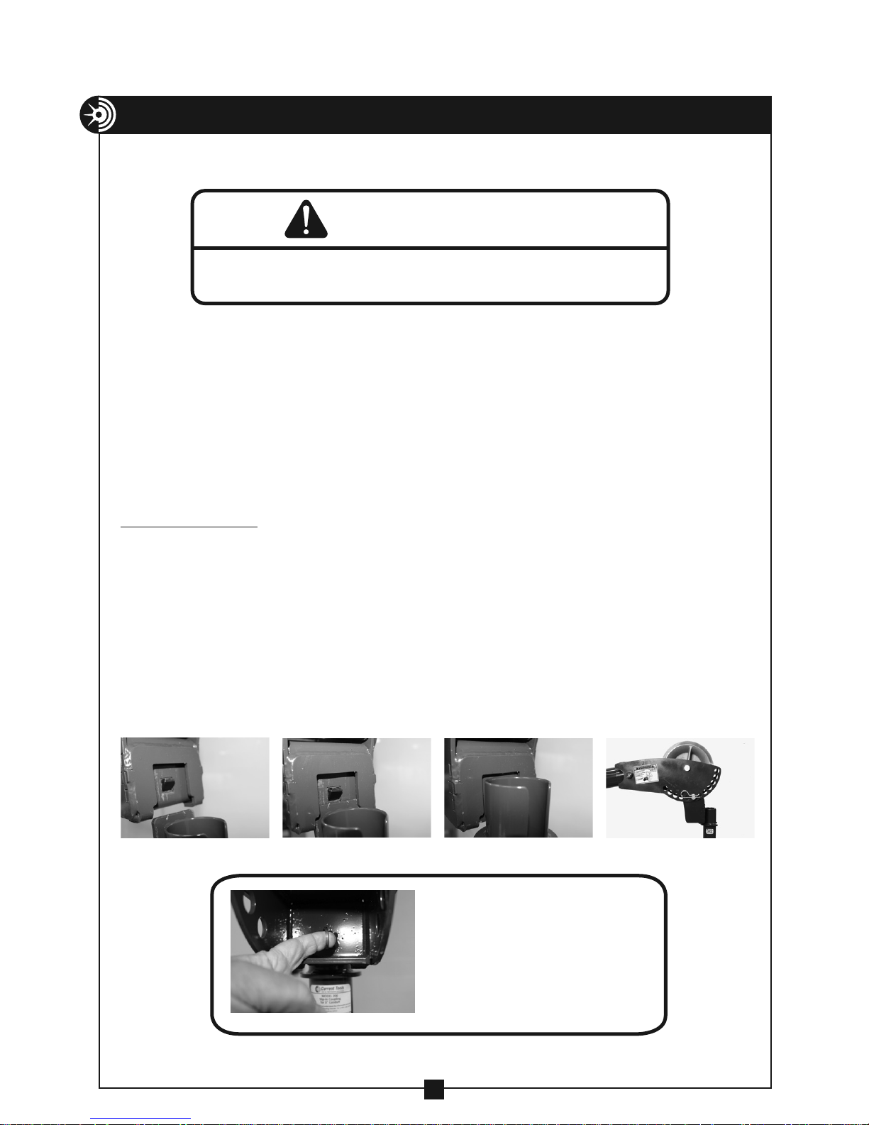
Slip-In Couplings Procedure:
1. Match the coupling to the conduit size.
2. Install the correct size slip-in coupling into the coupling adapter located in
the nose unit by inserting the receiver plate into the coupling adapter until
the spring loaded pawl "snaps" into place. See Figures 10a through 10d.
10a 10c10b 10d
NOTE: To disassemble
couplings from coupling
adapter, pull the ring on
the back of the coupling
adapter.This will retract
the spring loaded pawl
and release the coupling.
10e
10
Page 11
ASSEMBLY INSTRUCTIONS
CO
NDUIT MUST N
OT
EXTEND PA
S
OFCO
G
CO
T
G
(
)
O
— CONTINUED
Slip-In Couplings Used to Straddle Conduit
Slip-In Couplings can be used to straddle the conduit. One advantage of this is
the couplings can be straddled on conduit sizes smaller than 2 1/2". However,
the largest conduit you can straddle using a slip-in coupling is 5" (by using the
6" optional slip-in coupling).
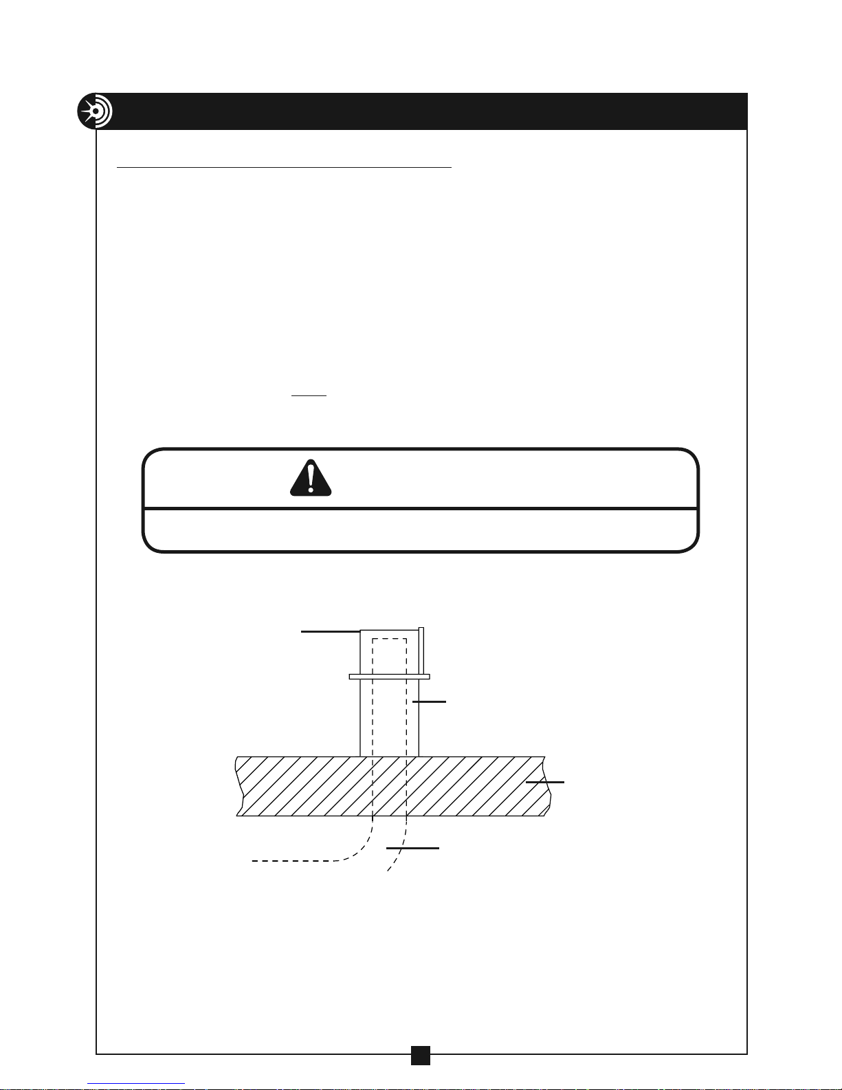
When using a slip-in coupling to straddle the conduit, the coupling must seat
against a concrete floor or similar structure capable of supporting 10,000 lbs. of
force.
Slip-In Couplings Used to Straddle Conduit Procedure:
1. Choose a coupling that is at least 1" larger than the conduit.
2. Place the coupling over the conduit. The conduit must NOT extend past the
end of the coupling. (See Figure 11a).
WARNING
Bottom of coupling must be seated against a structure capable of supporting 10,000 lbs.
T END
UPLIN
SLIP-INCOUPLIN
SHOWN STRADDLING
CONDUIT
STRUCTURECAPABLE
F SUPPORTING
10,000 LBS
NDUI
Figure 11a
11
Page 12
ASSEMBLY INSTRUCTIONS
(
CABLE PULLER )
CO
T
Screw-On Couplings
— CONTINUED
Screw-On Couplings, which thread onto the end
of Rigid or IMC conduit, are optional for conduit
sizes 2", 2 1/2", 3", 3 1/2" and 4".
Screw-On Couplings Procedure:
1. Match the coupling to the conduit size.
2. Thread coupling onto the conduit until tight.
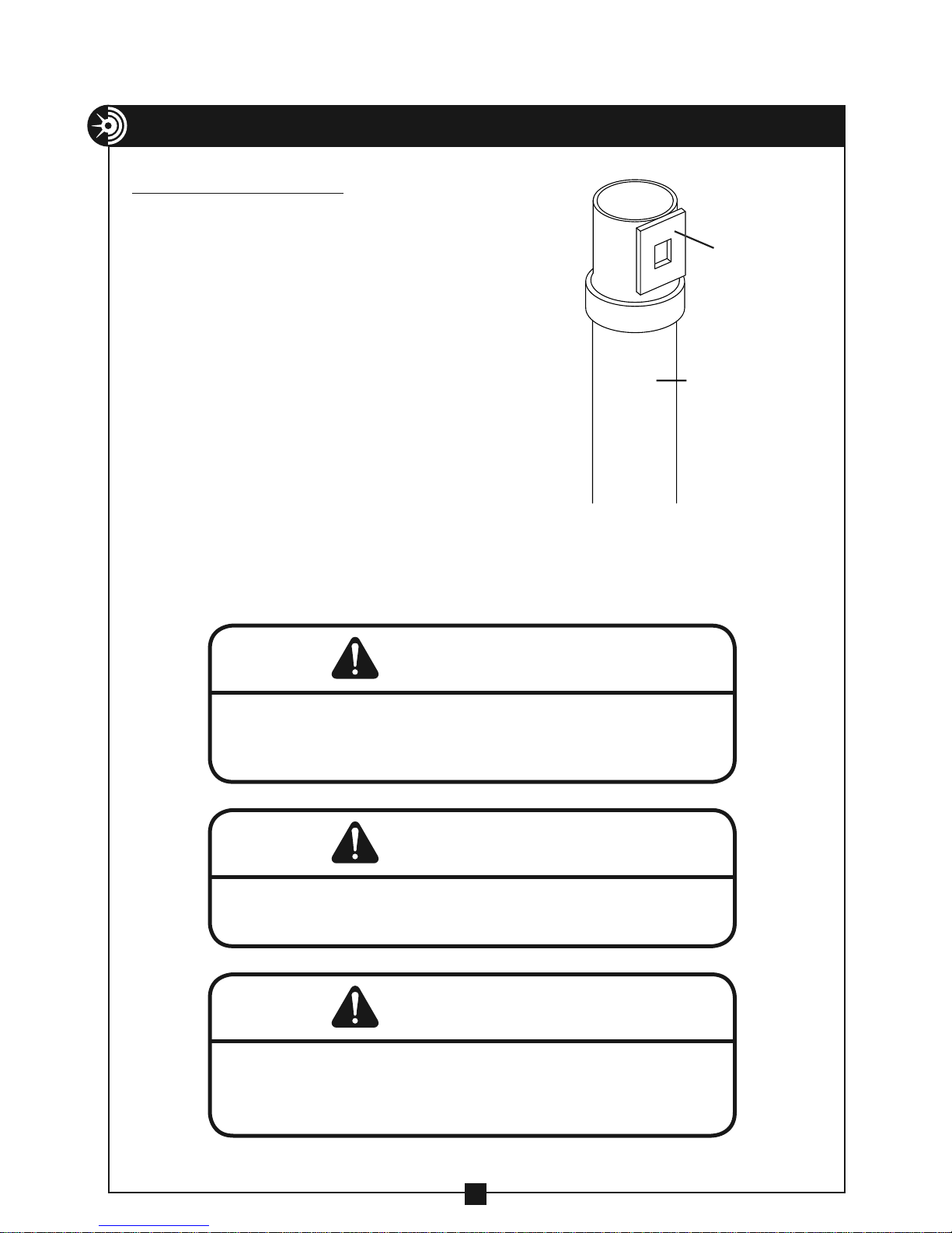
Then, slightly back off coupling until the
coupling receiver plate faces the direction
where the puller will be positioned. See
Figure 12.
3. Install the correct size coupling into the
coupling adapter located in the nose unit by
inserting the receiver plate into the coupling
adapter until the spring loaded pawl "snaps"
into place. See Figures 10a through 10d.
RECEIVER
TURN TO FACE
NDUI
Figure 12
WARNING
NOTE: To disassemble couplings from coupling adapter, pull the ring
on the back of the coupling adapter.This will retract the spring loaded
pawl and release the coupling. (See Figure 10e).
WARNING
Thread Screw-On Coupling onto conduit a minimum of 4 full turns. Inspect
the conduit threads to make sure they are in good condition.
WARNING
DO NOT use screw-on couplings when pulling in PVC conduit. Screw-on
couplings may detach and cause serious injury or death. When pulling in
PVC conduit, ONLY use slip-in couplings.
12
Page 13
ASSEMBLY INSTRUCTIONS
Boom Assembly
— CONTINUED
WARNING
ALWAYS inspect pins to be sure they are
fully inserted through holes and have spring
clips properly attached. DO NOT substitute
any other object for factory supplied pins.
WARNING
Some components weigh more than 50 lbs. and will require
more than one person to lift, transport and assemble.
Be careful during assembly and disassembly of the boom components. Keep
pins in place to avoid uncontrolled movement of boom components. Have
control of boom components before removing any pins.
WARNING
ALWAYS check sight holes to ensure boom
tubes are fully inserted into receiver tubes.
Ensure all spring loaded boom pins snap
into place to securely hold the boom tubes.
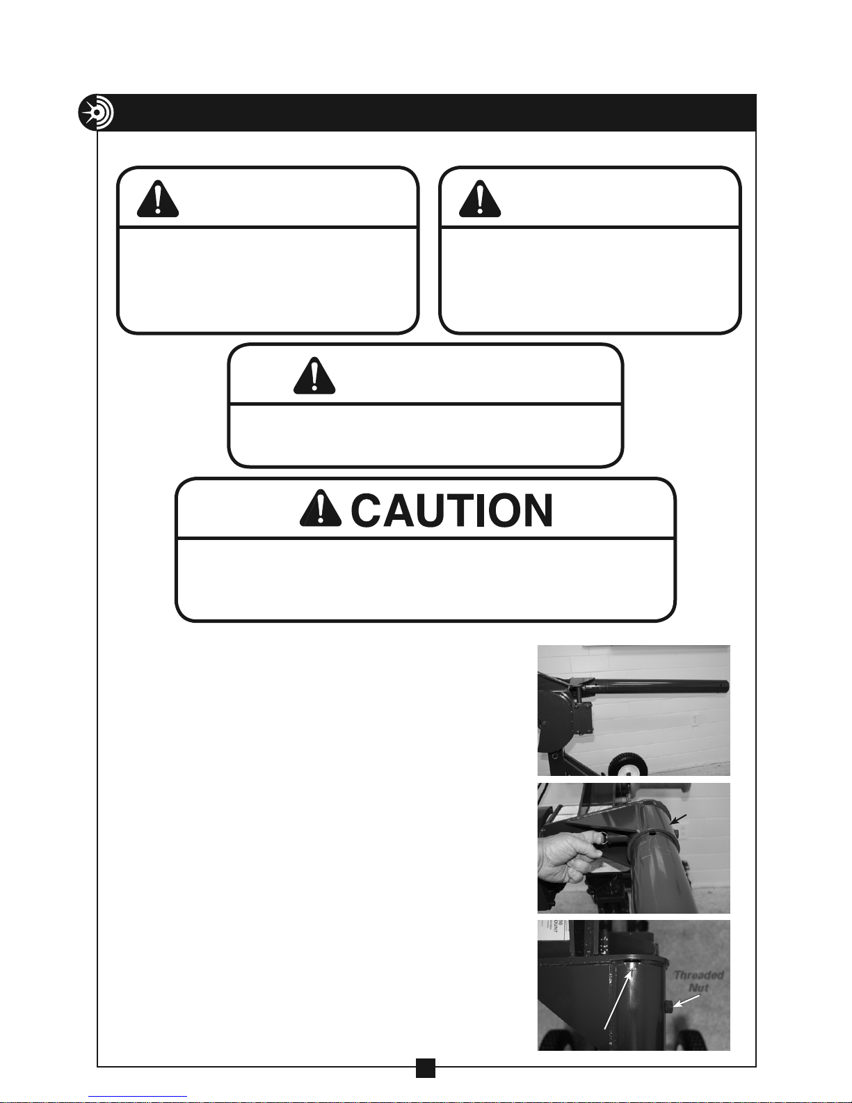
Procedure:
1. Lock the two swivel casters on the carriage.
Using the boom height adjustment handle,
position the puller mount with the receiver
tube parallel to the ground. Insert the supplied
3' or 4' boom tube into the reciever tube. (See
Photo 13a). Pull the spring-loaded boom pin
located on the receiver tube and fully insert
boom tube until it completely fills the sight
hole in the back of the receiver tube. (See
Photo 13b & 13c). Rotate the boom tube until
one of the pre-drilled holes in the boom tube
locks into place with the spring-loaded boom
pin. Ensure the spring-loaded boom pin is
fully engaged in the boom tube hole before
proceeding to the next step.
NOTE: When using pipe other than the boom
tubes supplied by Current Tools, fully insert
the pipe or conduit and install a 1/2-13 × 2"
bolt (user provided) into the threaded nut
on the side of the receiver tube and tighten
against the boom tube. (See photo 13C).
13a
13b
13c
Receiver
Tube
Threaded
Nut
Sight Hole
13
Page 14
ASSEMBLY INSTRUCTIONS
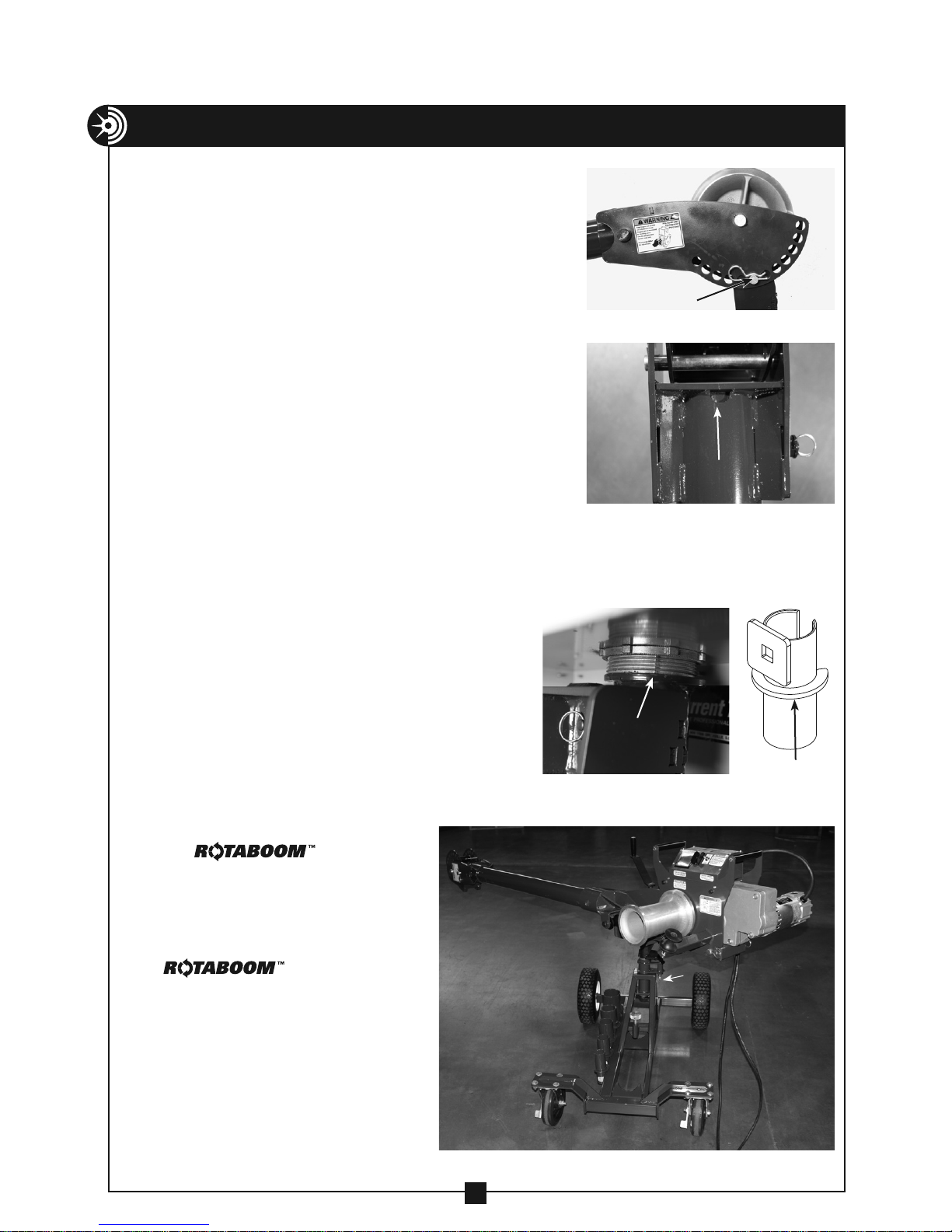
2. If only one boom tube is needed, slide the Model
#1840-S nose unit (or #1840 optional nose unit)
onto the boom tube you installed in Step #1. (See
Photo 14a). Determine the type of pull to be made
(up pull, down pull, side pull) and turn the nose
unit accordingly. Pull the spring-loaded boom pin
located on the nose unit and fully insert the nose
unit until it completely fills the sight hole. (See
Photo 14b). Rotate the nose unit until the springloaded boom pin locks it into the proper position
for the pull. Ensure the spring-loaded retainer
pin is fully engaged in the boom tube before
proceeding to the next step.
3. Choose the correct size coupling for the size
conduit that you will be pulling in and install it
into the coupling adapter on the nose unit. (See
coupling selection on pg. 10).
4. To insert the coupling into the conduit, unlock
the two swivel casters on the carriage and position the cable puller near the pull
sight. Using the boom height adjustment handle, raise or lower the boom until
the slip-in coupling fully seats in the conduit. The coupling is fully seated when
the coupling ring makes contact with the
conduit you are pulling in. (See Photo 14c).
It may be necessary to adjust the angle
of the coupling so that it seats properly in
the conduit. To do this, remove the spring
clip from the angle adjustment pin on the
nose unit, remove pin, and adjust the angle
of the coupling. When the correct angle is
achieved, re-insert the pin and secure with
the spring clip.
5. The Puller Mount offers a
patented feature known as
the that gives
the Puller Mount the ability
to swivel approximately 45
degrees in two directions. This
allows the puller to be used
in tighter spaces. To use the
, pull down
on the spring loaded retainer
pin located under the puller
mount and swivel the puller
as needed (see photo 14d).
Once the pull is completed
and you are ready to transport
the puller, return the puller
mount to the center position
and ensure the spring loaded
retainer pin snaps into place.
— CONTINUED
14
Nose Angle
Adjustment Pin
Sight Hole
Coupling
Ring
14c
Spring loaded
retainer pin
14d
14a
14b
Coupling
Ring
Page 15
ASSEMBLY INSTRUCTIONS
— CONTINUED
Elbow Unit Angle
Adjustment Pin
15a
15b 15c
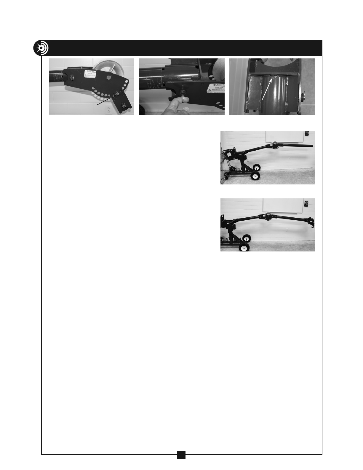
If more reach is needed, an extra boom tube
is provided. To install, continue assembly
instructions as follows:
NOTE: The extra boom tube can be stored on the
lower half of the carriage frame and secured with
the provided locking screw.
6. Remove the nose unit from the boom tube you
installed in Step #1. Slide the Model #1710 elbow
unit onto the end of the boom tube as shown in
Photo 15a. Pull the spring-loaded boom pin on
the elbow unit and fully insert the elbow unit until
it completely fills the sight hole. (See Photos 15b
& 15c). Rotate the elbow unit until the springloaded boom pin locks it into the proper position
for the pull.
7. Slide the additional boom tube into the elbow
unit. Pull the spring-loaded boom pin on the
elbow unit and fully insert the additional boom
tube until it completely fills the sight hole. Rotate
the boom tube until the spring-loaded retainer pin locks it into position.
(See Photo 15d).
Sight Hole
15d
15e
8. Refer to step #2 in the assembly instructions section and install the model #1840-S
nose unit (or #1840 optional nose unit) on the end of the additional boom tube
(see photo 15e).
9. If angle adjustment is needed, remove the spring clip from the elbow unit angle
adjustment pin, remove the pin and adjust the angle to the desired degree. When the
correct angle is achieved, re-insert the pin and secure with the spring clip.
10. You are now ready to pull cable.
11. If more reach is required, both the 3' and 4' lengths of factory supplied boom tubes
may be replaced with up to 10' lengths of 3" rigid conduit or 3" schedule 40 pipe. ONLY
use 3" rigid conduit or 3" schedule 40 pipe for boom tubes. NEVER substitute any other
size or type of conduit or pipe for boom tubes. NEVER replace factory supplied boom
tubes with shorter boom tubes.
NOTE: The weight of boom sections longer than the factory supplied booms will
require manual assistance to use the boom height adjustment handle.
IN ADDITION, screw-on couplings may be necessary to support the boom and
prevent it from falling.
15
Page 16
COMMON SET UPS
Hex Head Bolt
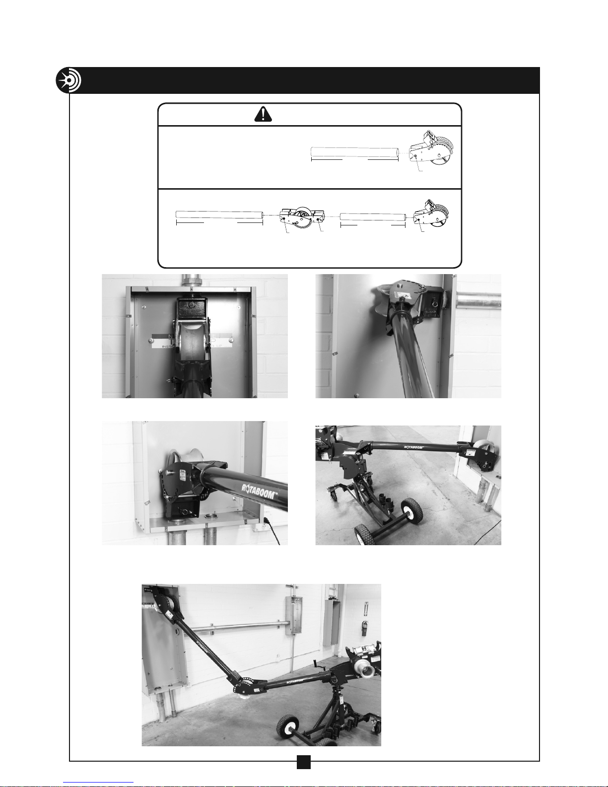
When using one boom tube and nose unit, factory supplied boom tube may be replaced but must meet
the following specifications:
• Only use 3" schedule 40 pipe or 3"
rigid conduit
• Check sight holes to be sure boom tubes are fully
inserted. Then tighten 1/2-13 × 2" hex bolt (user
provided).
When using elbow unit, nose unit and both boom tubes, factory supplied boom tubes may be replaced
but must meet the following specifications:
WARNING
• DO NOT transport the puller on the
carriage with boom tubes other than the factory
supplied 3' and 4' tubes.
3' min. to 10' max.
1/2-13 × 2"
Hex Head Bolt
• Only use 3" schedule 40 pipe or 3"
rigid conduit
• Check sight holes to be sure boom
tubes are fully inserted. Then tighten
1/2-13 × 2" hex bolt (user provided).
3' min. to 10' max.
1/2-13 × 2"
Hex Head Bolt
• DO NOT transport the puller on the carriage with boom tubes
other than the factory supplied 3' and 4' tubes.
1/2-13 × 2"
Hex Head Bolt
3' min. to 10' max.
Down Pull Side Pull
1/2-13 × 2"
Up Pull Up Pull using RotaBoom™
feature and one boom tube
Down Pull using elbow
unit and nose unit with
RotaBoom™ feature
16
Page 17
TRANSPORT INFORMATION
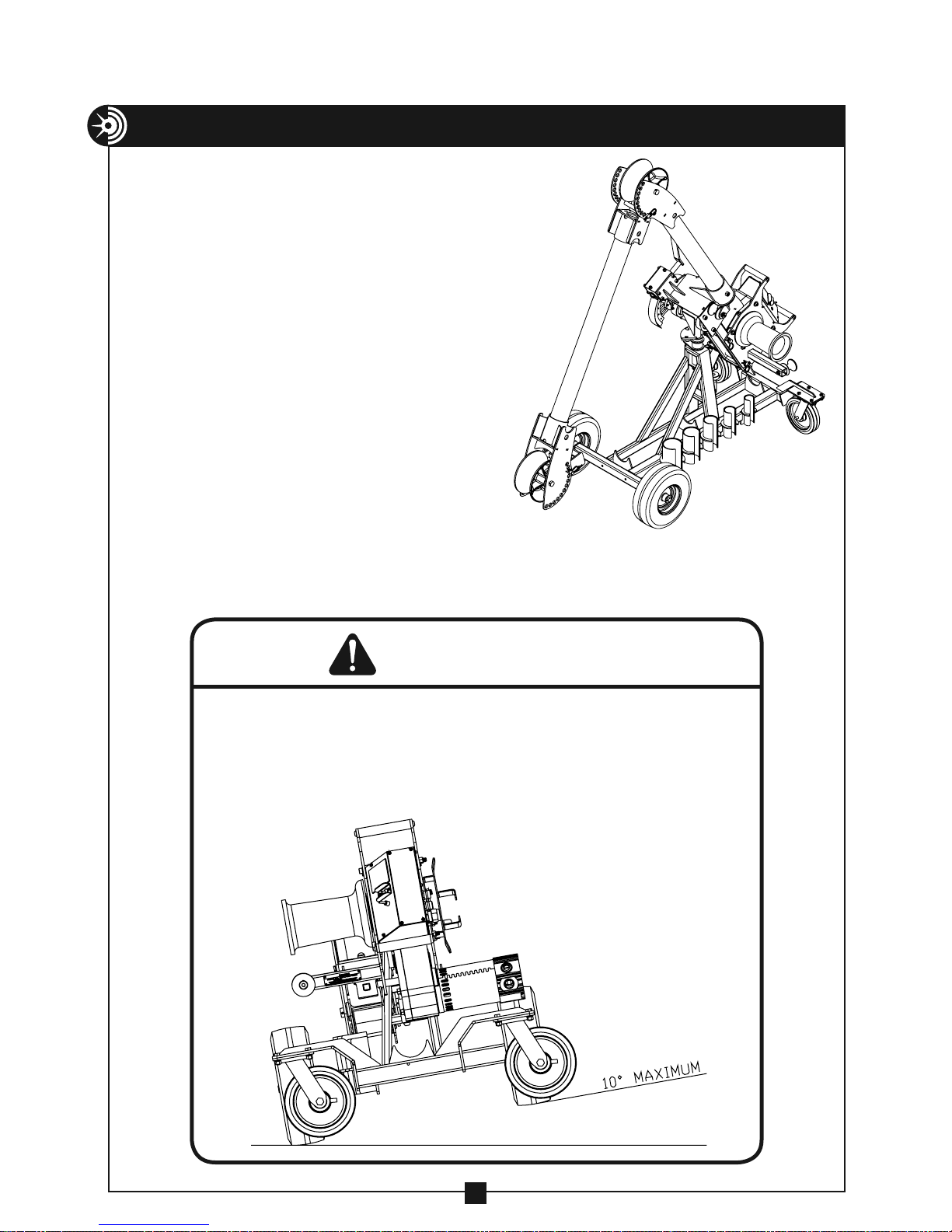
The Mobile Carriage is designed to
easily move the Pulling Assembly from
location to location.
To Prepare for Transport
Before moving, use the boom height
adjustment handle and raise the boom
tube as shown in Figure 17. If both
sections of the standard boom tubes are
installed, remove the elbow unit angle
adjustment pin and rotate the forward
section down as far as possible (See
Figure 17). Reinstall the elbow unit angle
adjustment pin. DO NOT transport with
boom tubes longer than the factory
supplied 3' and 4' sections.
NOTE: ALWAYS return the puller mount
to the center position and ensure the
spring loaded retainer pin snaps
into place prior to transport.
Figure 17
WARNING
• Tip Hazard — DO NOT lean unit more than 10°.
• DO NOT transport with boom tubes longer than
the factory supplied 3' and 4' sections.
• Only transport on firm, smooth surfaces.
• Keep unit under control when transporting.
17
Page 18
FLOOR/CHAIN MOUNT
WARNING
DANGER
The Model #2280 floor mount and #2281 chain mount are made to fit the
Current Tools Model #1450 Cable Puller and can be mounted using two
different procedures as noted on pages 18 through 22.
PROCEDURE #1
Mounting to a concrete floor
(Model #2280 floor mount)
Safety Information
1. ALWAYS mount to a smooth,
flat concrete floor with a
minimum 3000 psi rating.
2. Mount only to a concrete floor.
NEVER mount to cinder blocks,
brick, etc.
3. Wedge anchors must be at least
12" away from edge of concrete.
4. ALWAYS use new anchors.
NEVER REUSE ANCHORS.
5. Use only 5/8" x 6" wedge anchors or equivalent with a tension and shear
rating of 2,500 lbs. (Current Tools part #8045-3)
6. ALWAYS wear eye protection when installing anchors.
CAUTION
WARNING
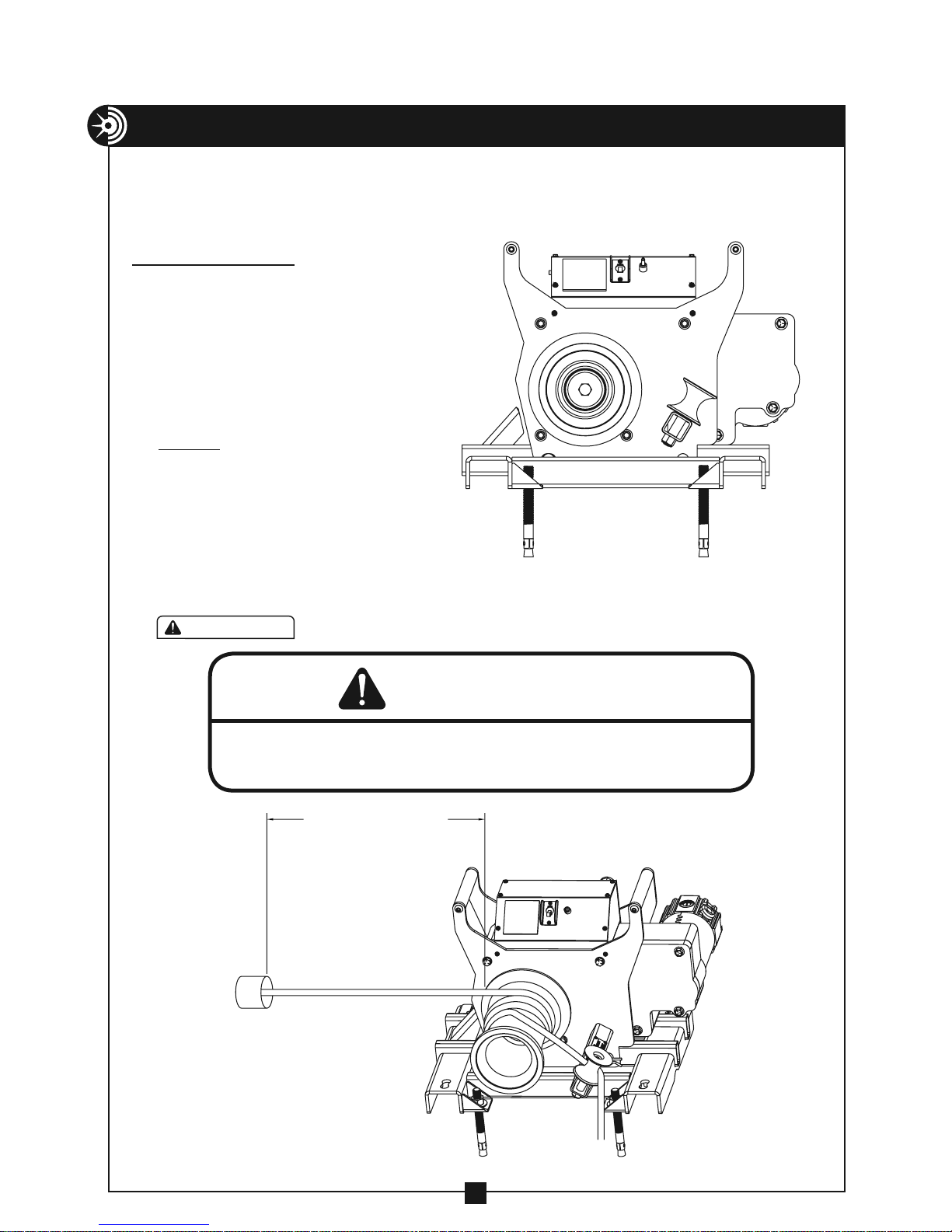
ALWAYS place the Model #2280 floor mount close to the conduit. This will
reduce the possibility of injury should the rope break. See Figure 18a.
PLACE CLOSE TO CONDUIT
Figure 18a
18
Page 19
FLOOR/CHAIN MOUNT
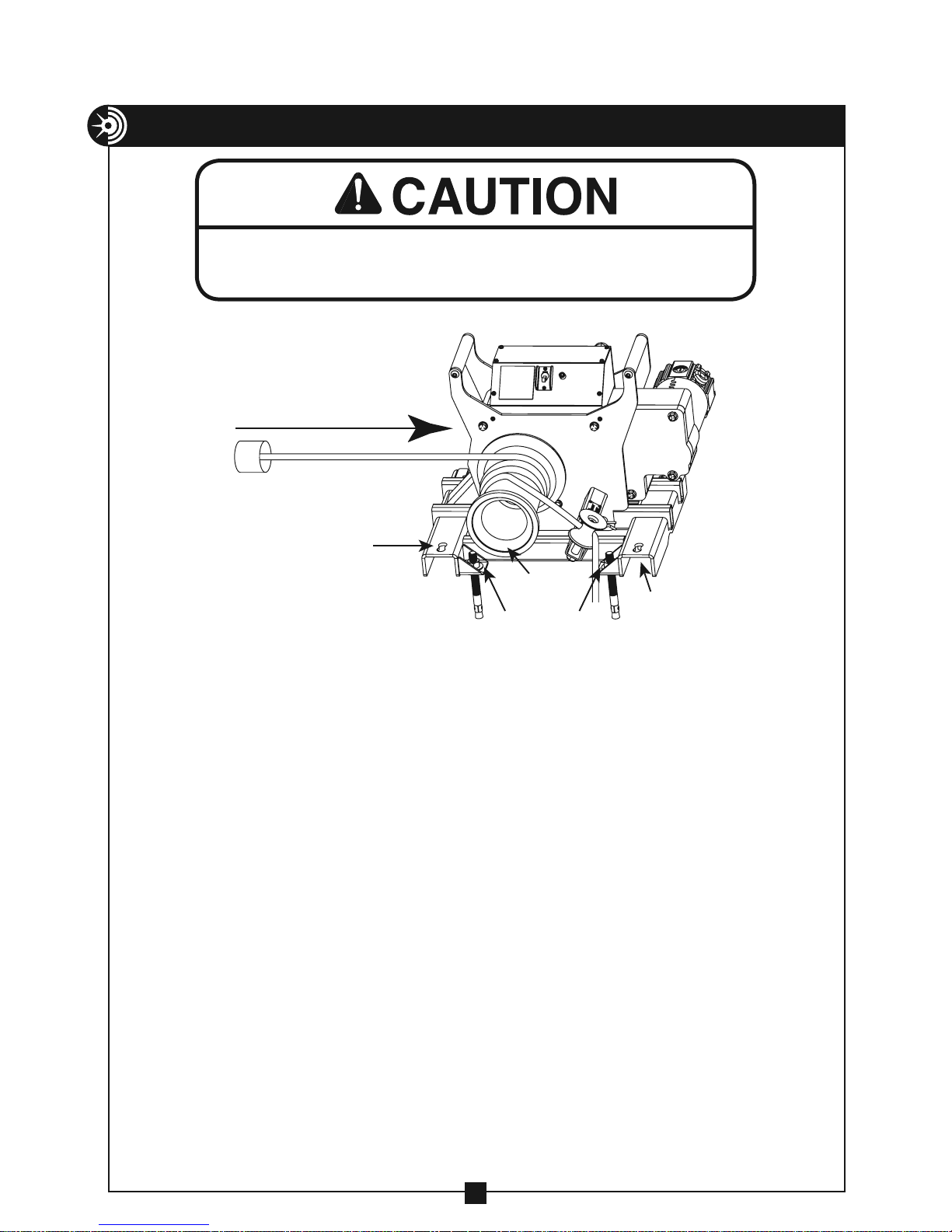
The pulling direction should ALWAYS be parallel to the base of the floor
mount. See Figure 19.
— CONTINUED
CORRECT
PULLING
DIRECTION
Figure 19
mounting chain
handle hole
capstan
mounting chain
Installation Instructions
1. Wear safety glasses.
2. Follow the safety instructions provided by the drill manufacturer.
floor mount
holes (4 places)
handle hole
3. Use only 5/8" diameter solid carbide tipped bits that meet ANSI B94-12.
4. Using the floor mount as a template, drill four 5/8" holes a minimum of
6" deep but not closer than 1 1/4" to the bottom (opposite surface) of the
concrete. Be sure to drill the holes perpendicular to the work surface and
do not ream the holes or let the drill bit wobble.
5. Clean the holes with compressed air and a wire brush. Clean holes are
necessary for proper performance.
6. Assemble the washer and nut on the anchor so the top of the nut is flush
with the top of the anchor.
7. Next, drive the 4 wedge anchors through the 4 floor mount holes (See
Figure 19 and 20a) and into the concrete holes, making sure the nut and
washer rests solidly against the floor mount.
8. Tighten the anchors with a torque wrench to 75-90 ft. lbs.
NOTE: If anchor spins, pull up on the anchor using the claw end of
hammer and then torque. If spinning still occurs, DO NOT use this
location; reposition the floor mount and repeat this installation procedure.
9. Install model #1450 puller onto the floor mount by lowering the puller
over the floor mount and inserting the puller mount pins (see Figure 20b).
Secure the puller mount pins with spring clips. NOTE: The puller MUST be
mounted onto the floor mount with the capstan on the same side as the
mounting chain handle holes (see Figure 19).
19
Page 20
FLOOR/CHAIN MOUNT
— CONTINUED
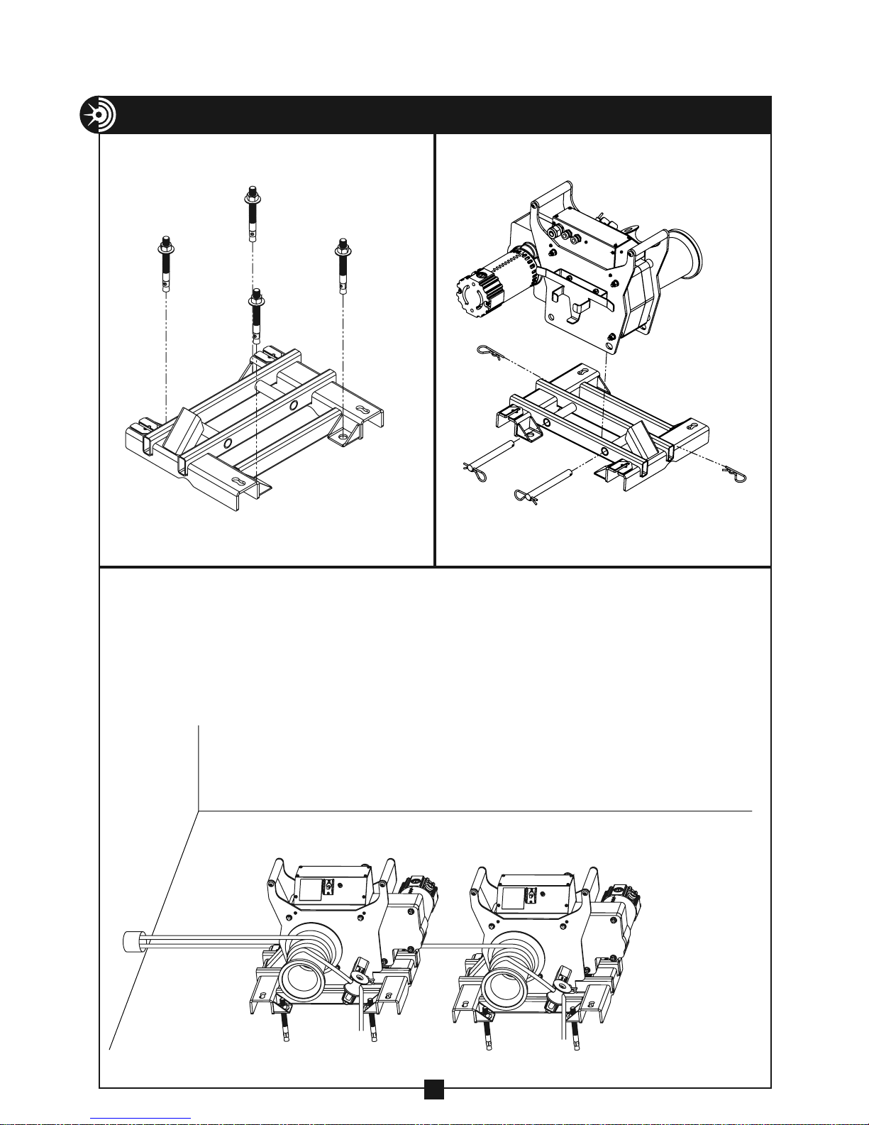
Floor Mount Anchor Holes Installing Puller on Floor Mount
Figure 20a Figure 20b
Tandem Pulling
If the amount of pulling force required to make a pull exceeds the load rating
for a single cable puller, two cable pullers may be used in tandem to make
the pull. (See Figure 20c below). Be sure to use a separate rope and set of
accessories for each cable puller. Each set of rope and accessories should
meet or exceed each cable pullers maximum pulling force.
Figure 20c
20
Page 21
FLOOR/CHAIN MOUNT
N
O
OK
OK
— CONTINUED
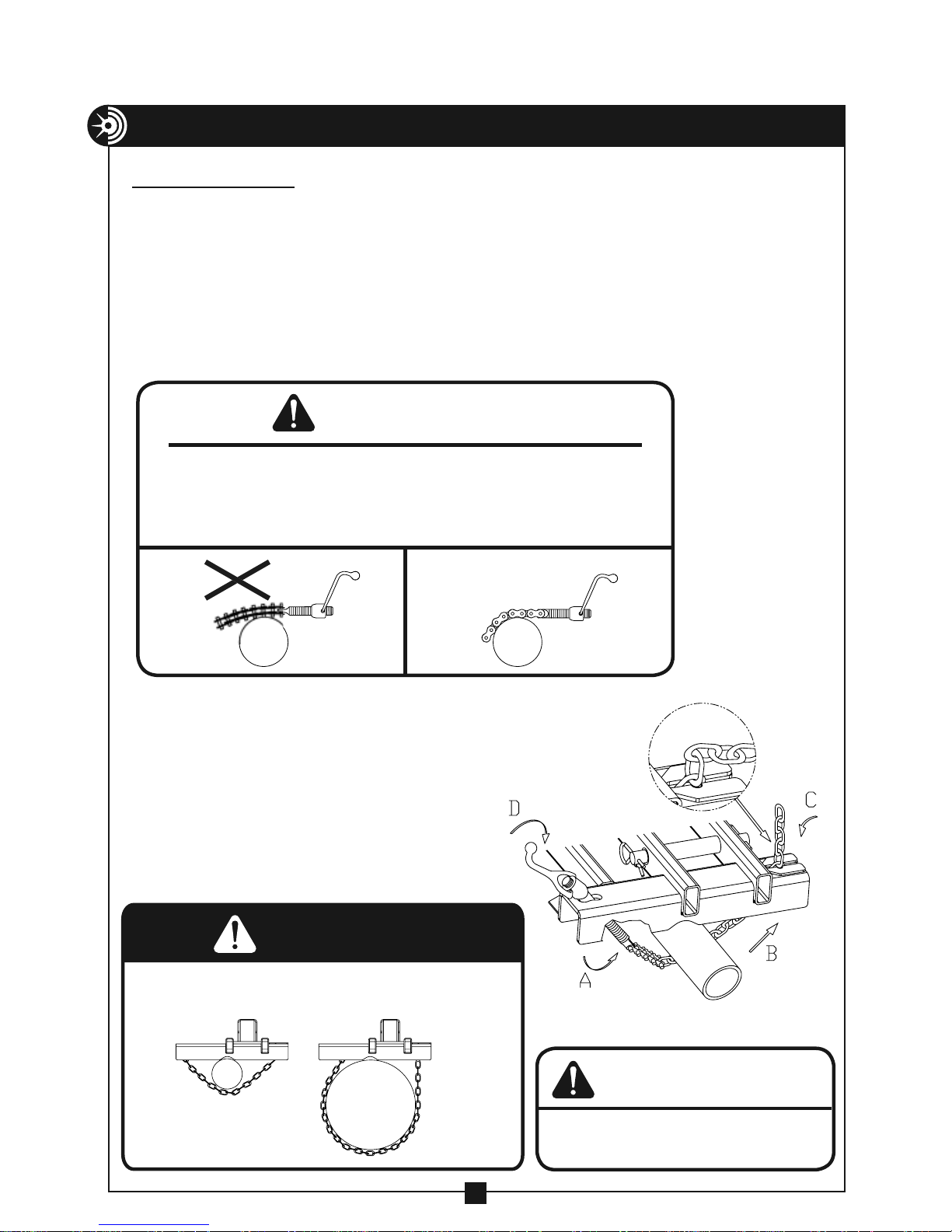
PROCEDURE #2
Mounting Chain Instructions
(Model #2281 chain mount)
The Model #2281 chain mount is designed to be secured to conduit or
structural supports using the two chains provided. The handles on the chains
should provide sufficient leverage to tighten the chains securely. No other
tools are needed. Be sure to check the mounting chains for kinks and twists
before you tighten them. See Warning below for proper mounting chain
installation.
WARNING
When using the Model #2281 chain mount, never tighten chain as shown in Figure
A. This causes side loading of the chain and can result in failure of the chain or
screw causing components to come loose and possibly cause serious injury or
death. Figure B shows the proper alignment of screw and chain for tightening.
Figure A
A Loosen the mounting chain handle so that
only 3 or 4 threads remain engaged.
B Wrap the chain around the floor mount,
conduit or structural support sufficient to
handle the pulling forces.
C Pull the loose end of the mounting chain
tight and hook the closest chain link into
the recessed area.
D Tighten the chain handle. Repeat this
process for second mounting chain.
DANGER
ALWAYS ensure cable puller is properly secured before operating.
ALWAYS attach to supports that are at least 2" and not more
than 10" wide.
OK TOO WIDE
Figure B
WARNING
Be sure threads do not bottom out before
chain becomes tight.
21
Page 22
FLOOR/CHAIN MOUNT
O
OK
OK
MOUNT PINS
PULLER
— CONTINUED
CAPSTAN
MOUNTING CHAIN
HANDLE HOLE
Figure 22
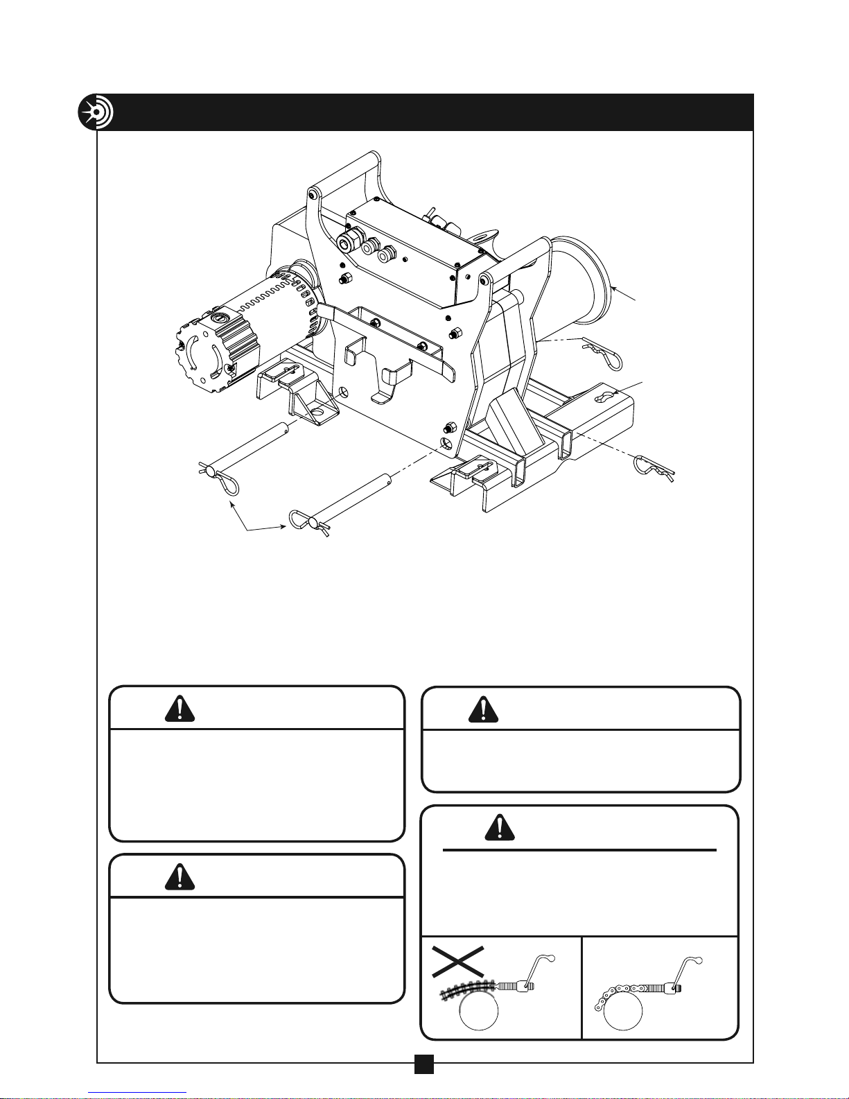
NOTE: Install Model #1450 puller onto the chain mount by lowering the puller
over the chain mount and inserting the puller mount pins (See Figure 22).
Secure the puller mount pins with spring clips. The puller MUST be mounted
onto the chain mount with the capstan on the same side as the mounting
chain handle holes. (See Figure 19).
WARNING
1. The only approved method to secure the Model #2281
chain mount is with the 2 mounting chains provided. DO
NOT attempt to use any other object to secure the puller.
2. Inspect the mounting chains for wear before each
installation.
3. NEVER alter the mounting chains or handles.
WARNING
ALWAYS inspect the structural integrity of any supports,
conduit, anchoring system etc. that will hold the cable puller
during the pull. These supports should be able to withstand
the maximum pulling force of the cable puller plus a safety
factor of 3:1. Example: 10,000 lb. puller should be anchored
to a support that can withstand 30,000 lbs. of pull.
DO NOT mount the Model #2281 chain mount to square columns
or I-Beams. The mounting chains will not tighten properly on these
structures.
When using the Model #2281 chain mount, never tighten chain as
shown in Figure A. This causes side loading of the chain and can
result in failure of the chain or screw causing components to come
loose and possibly cause serious injury or death. Figure B shows
the proper alignment of screw and chain for tightening.
WARNING
WARNING
N
Figure A Figure B
22
Page 23
FEATURES
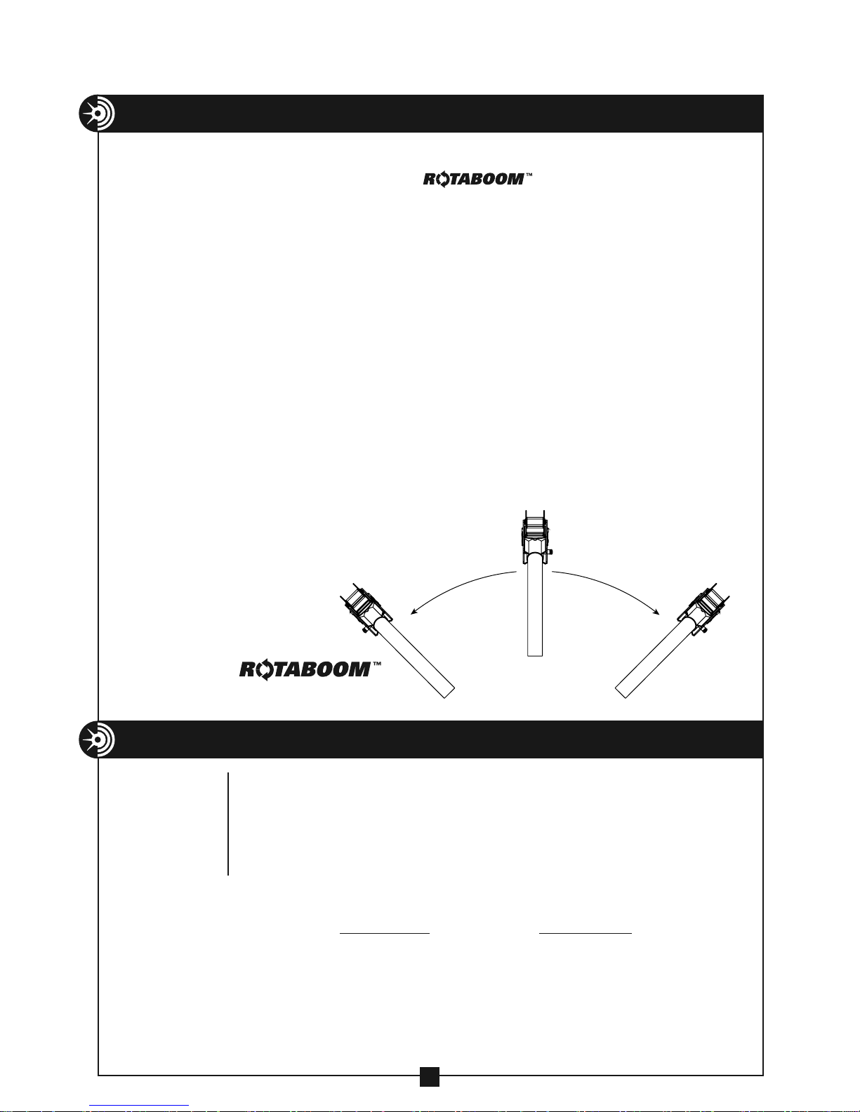
• One person set up
• Patented 45 degree horizontal pivot allows for use of
puller in tight spaces. See drawing below.
• Built-in force gauge with digital read out and color screen to indicate
force ranges
• Circuit breaker on/off switch — helps protect motor
• Two speeds
• Built-in time delay – helps protect motor
• Puller ready light gives visual confirmation that puller is ready for use
• Safety pawl on capstan sprocket to prevent reverse rotation
• Tapered capstan to help avoid rope overlap
• Tailing rope safety roller for operator safety — lets operator stand out
of the direct line of tight pulling rope
• Two handles for carrying or positioning puller
• Simple electrical system for easy maintenance
• Boom height adjustment handle allows for
easy vertical positioning of boom sections
• Integrated foot switch
45˚
Patented
Boom pivots 45°
Patent #9,899,811
SPECIFICATIONS
SPECIFICATIONS — MODEL 1450 CABLE PULLER
in either direction
to fit in tight spaces.
45˚
Model no. 1450 Cable Puller
width 24"
length 19 1/4"
height 15"
weight 119 lbs.
maximum pulling force — 10,000 lbs.
Low Speed High Speed
speeds (approx.) no load — 12 FPM no load — 48 FPM
2,000 lbs. — 11 FPM 1,000 lbs. — 36 FPM
4,000 lbs. — 10 FPM 1,500 lbs. — 29 FPM
6,500 lbs. — 8 FPM 2,000 lbs. — 24 FPM
motor — 120 volts AC, 60 hertz, 20 amps
23
Page 24
FEATURES — MODEL 1450 CABLE PULLER
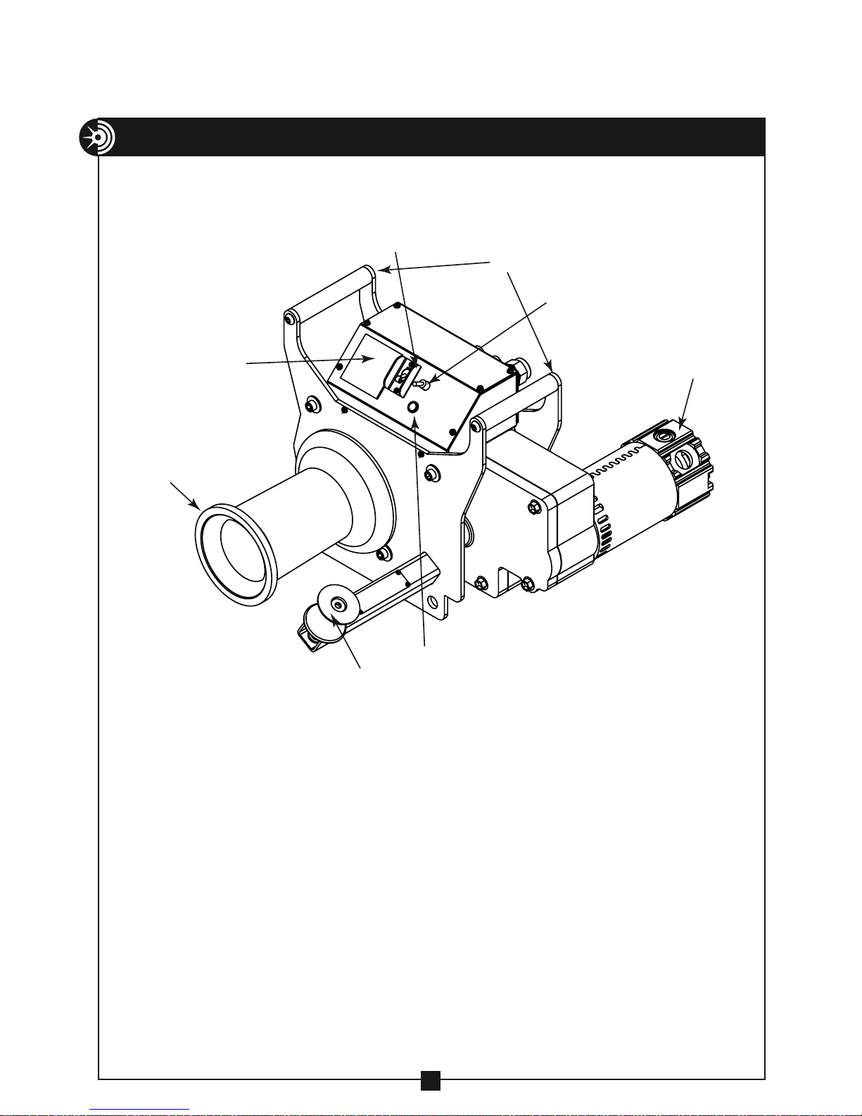
T
Capstan
20 Amp Motor
On/Off Circuit
Digital Force
Gauge
apered
Breaker Switch
Carry
Handles
High/Low
Speed Switch
Puller Ready Light
Safety Roller
24
Page 25
CABLE PULLING BASICS
Model 1450 Cable Puller and Accessories
The Model 1450 Cable Puller has a maximum pulling force of 10,000 lbs. Therefore,
all of the accessories used to make a cable pull with this unit must be rated to meet or
exceed the forces generated. This includes, but is not limited to pulling rope, sheaves,
swivels, grips, etc. Be aware that the pulling force on a sheave and its anchoring
system can be as great as twice the pulling force generated by the cable puller.
Force Gauge
The Model 1450 Cable Puller is equipped with an built-in force gauge. The
operator should always monitor the force gauge throughout the entire cable pull.
The force gauge has 3 color screens to help you identify operating conditions.
These screens are:
COLOR PULLER FORCE CONDITION
Green 0-6,500 lbs. Puller can be run continually
White 6,500 lbs. -8,000 lbs. 50% duty cycle; 5 minutes on / 5 minutes off
Flashing Red 8,500 lbs. -10,000 lbs. Overload condition — momemtary operation
of puller only. Correct the overload condition.
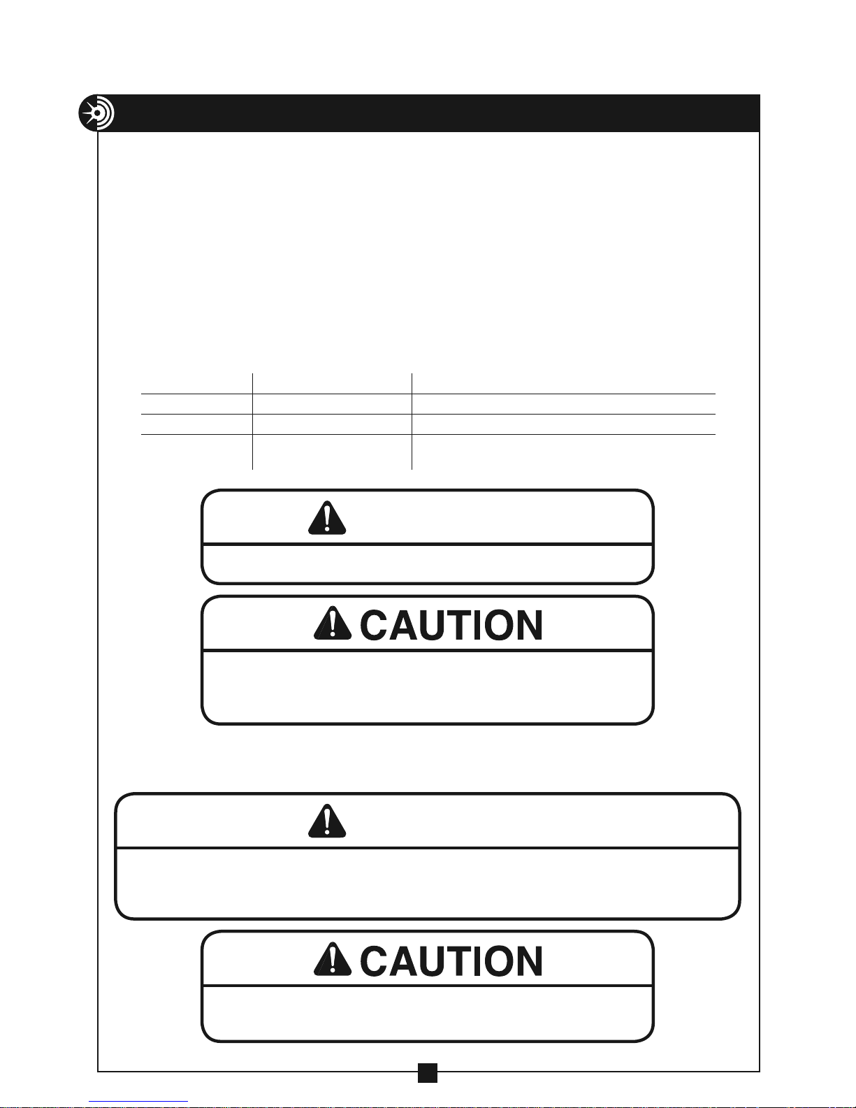
WARNING
DO NOT exceed load rating of cable puller, rope or accessories.
Inspect all components of the pulling system before beginning any cable pull.
This includes the pulling system (cable puller, boom, etc.) and any accessories
( sheaves, swivels, pins, etc. ) Replace any worn or defective components.
Power Requirements
The Model 1450 Cable Puller motor is rated at 120 volt – 60 hz – 20 amps.
ALWAYS plug the Model 1450 Cable Puller into a grounded receptacle with a 20 amp GFCI protected circuit.
DO NOT modify the plug provided with the Model 1450 Cable Puller. If needed, have a 20 amp GFCI
receptacle installed by a qualified electrician.
If an extension cord is used, it should be a minimum of 12 gauge wire with
ground and a maximum length of 100 ft.
WARNING
25
Page 26
CABLE PULLING BASICS
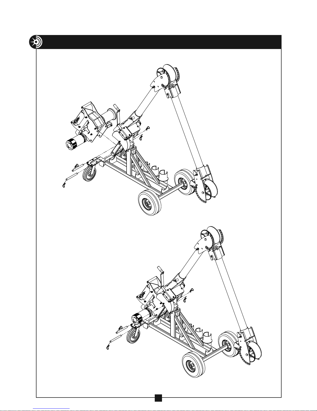
Model 1450 Cable Puller — mounting to Model 1190 Puller Mount.
— CONTINUED
26
Page 27
OPERATING INSTRUCTIONS — MODEL 1450 CABLE PULLER
DO NOT operate cable puller in wet or damp locations. Do NOT expose to rain.
DO NOT operate in an explosive atmosphere.
DO NOT use cable puller as a hoist or for lifting, supporting or transporting
people or loads. Use only for its intended purpose as a cable puller.
Rope Set-Up
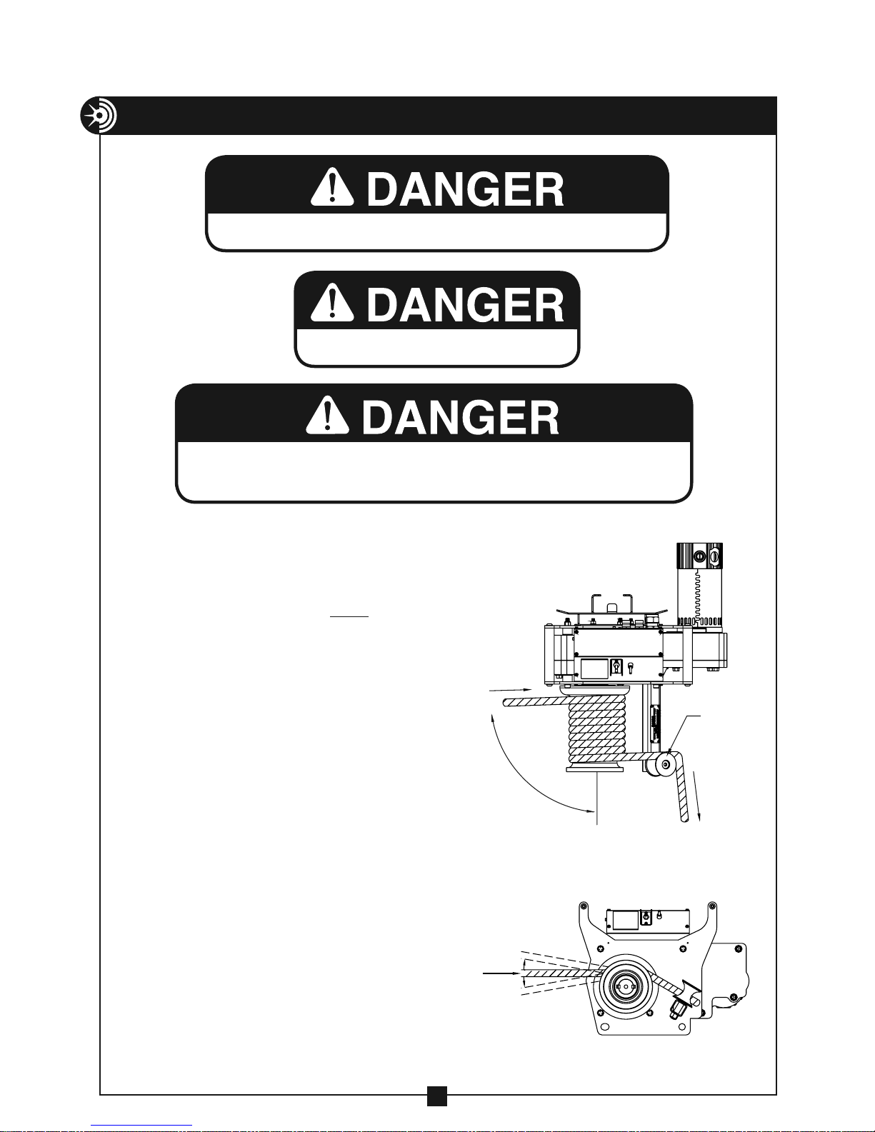
As shown in the overhead view,
Figure 27a, the pulling rope must
approach the capstan at a 90º
angle. This will help avoid rope
overlap.
Make several wraps of the
pulling rope around the capstan,
beginning at the housing end of
the capstan. See Figure 27a.
Next, guide the pulling rope
around the black safety roller as
shown in Figure 27a. This will
enable the operator to stand at
a 90º angle to the cable puller
and out of the direct line of tight
pulling rope.
Also note the pulling rope
should approach the capstan as
indicated in Figure 27b.
DIRECTION
Figure 27a
PULL
DIRECTION
PULL
90˚
MAXIMUM
10˚
MAXIMUM
10˚
OVERHEAD
VIEW
SIDE
VIEW
BLACK
ROLLER
TO
OPERATOR
Figure 27b
27
Page 28
OPERATING INSTRUCTIONS
WARNING
OPERATING INSTRUCTIONS
Rope should approach capstan as shown in Figure 27b.
ALWAYS use black roller to guide rope so that operator stands at 90°
angle to the cable puller and out of the direct line of tight pulling rope.
See Figure 27a.
ALWAYS wrap rope beginning at housing end of capstan as shown in
Figure 27a.
To help avoid rope overlap, rope must approach capstan at a 90° angle.
See Figure 27a.
WARNING
Rope Requirements: Use only 7/8" or larger double-braided composite pulling
rope, or a pulling rope with a minimum average breaking strength of 32,000 lb.
— CONTINUED
— CONTINUED
Be sure to inspect rope for damage before each cable pull.
CAUTION
Wear eye protection when operating
cable puller.
Pulling Operation
1. Be sure the cable puller circuit breaker switch is in the off position.
2. Select High or Low speed as indicated on the puller.
3. Operator should be able to see and monitor the force gauge throughout the
entire cable pull.
4. Hold the tailing end of the pulling rope as it comes off the black safety roller (see
Figure 27a) and pull slightly. Turn the cable puller circuit breaker ON.
Note: There is a built-in delay when switching unit on or when changing speeds.
The puller ready light in the electronics box will illuminate green when the puller is
ready for use.
There is a built-in delay when switching the
unit on or when changing speeds.
ATTENTION
Note: The tailing rope is that portion of the pulling rope that has passed the capstan
and is now excess to the pull. By pulling on the tailing rope the operator can control
and vary the pulling force. It should require no more than 10 lbs. of tailing force
by the operator to engage the pulling rope on the capstan. If the rope slips on the
capstan, turn the puller off and add an additional wrap of rope around the capstan.
Also note that with the tailing force at a constant pull, each additional wrap of rope
around the capstan will approximately double the pulling force of the cable puller.
28
Page 29
OPERATING INSTRUCTIONS
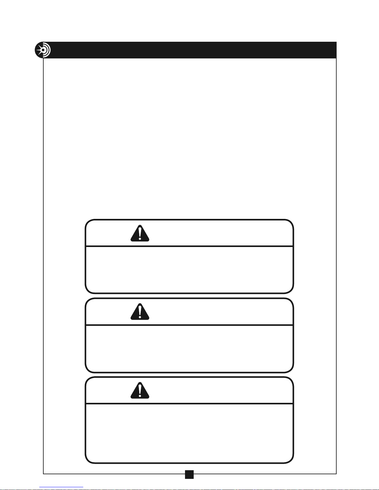
5. Once the puller ready light mounted in the electronics box is lit, depress the foot
switch to activate the puller. As the rope is tailed, it should mound on the floor
between the operator and the cable puller.
6. Release pressure off of the foot switch to stop the puller. Turn the cable puller
circuit breaker switch to the OFF position when the pull is completed.
NOTE: If for any reason you need to stop during a pull, release pressure on
the foot switch, turn the cable puller OFF and tie off the tailing rope to hold
it in place.
NOTE: The Model 1450 Cable Puller is equipped with a circuit breaker
switch. If the amperage rating of the breaker is exceeded the puller
will switch off. Before restarting the pull, allow the motor to cool and
determine the cause for the overload condition. Correct before restarting
the pull.
NOTE: There is a built-in delay when switching the unit on or when
changing speeds. The puller ready light in the electronics box will
illuminate green when the puller is ready for use.
— CONTINUED
WARNING
NEVER allow the rope to slip on a rotating capstan for more than a
couple of seconds. The rope will wear in that spot and the rope could
break under pressure. If you need to stop the pull, turn the cable puller
off and tie the rope off to hold it in place until you restart your pull.
WARNING
This cable puller is equipped with an anti-reversing pawl. The pawl will
make a clicking sound when the capstan is rotating. if you can not hear
the clicking sound as the capstan rotates, immediately turn the cable
puller off and do not use until repaired.
WARNING
Keep all body parts, hair, loose clothing, etc. away from rotating parts
and pinch points. Keep hands away from capstan.
DO NOT wrap rope around any body parts. DO NOT wrap rope around
wrists.
ALWAYS keep the tailing rope away from the operator’s feet.
29
Page 30
OPERATING INSTRUCTIONS
WARNING
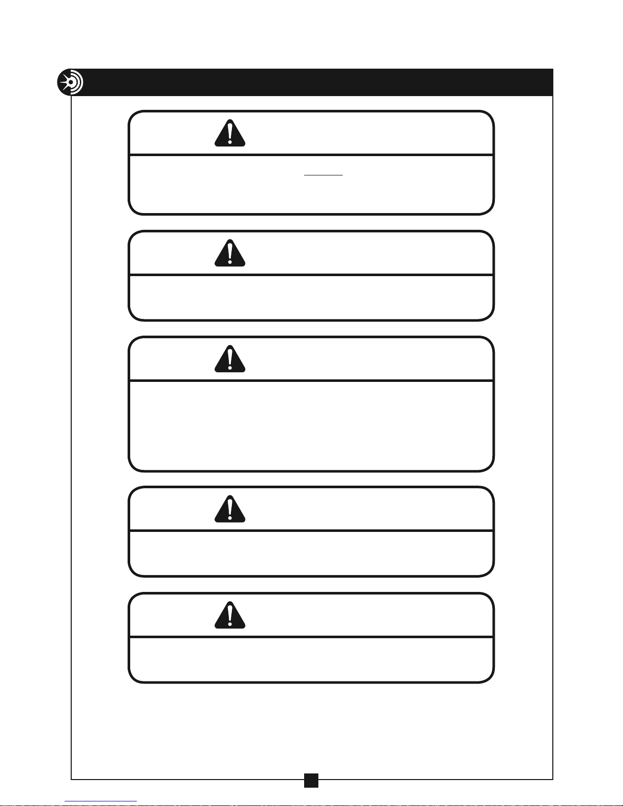
Rope must ALWAYS be pulled over a rotating sheave. If a sheave does not
rotate, turn cable puller off immediately and determine the problem before
continuing the pull.
WARNING
Pulling Rope should be the only thing to contact the capstan. NEVER let
swivels, grips, etc. come in contact with the capstan.
WARNING
— CONTINUED
NEVER allow the rope to overlap on the capstan. If this condition begins to
occur, immediately release the tailing force on the rope so that the rope
can feed back toward the conduit or cable tray. If this does not remedy the
overlap, turn off the cable puller immediately. There is no known solution
for rope overlap.
WARNING
Keep as much rope confined in the conduit as possible. This will help
prevent injury should the rope break and whip violently.
WARNING
When making a vertical cable pull, keep the area underneath the cable pull
clear of all personnel.
30
Page 31
MAINTENANCE
DO NOT alter this cable puller. Doing so will void the warranty.
Guards and safety features are provided for your protection.
Capstan
Replace the capstan if it is grooved more than 1/16” deep.
WARNING
Unplug the cable puller before servicing.
Lubrication
Wheels and casters — Grease as needed with a good quality
multi-purpose grease. Grease fittings are located on the wheel
and caster.
Worm Box Assemby — Grease as needed with a good quality
multi-purpose grease. Start with puller mount in fully upright
(transport) position and insert one pump of grease. Rotate
worm box handle one full turn and insert another pump of
grease. Continue this sequence until puller mount is fully in
the down position. Grease fitting is located on the side of the
worm box assemby.
Inspection
Motor Brushes – Inspect the two motor brushes every 30
hours. Replace if less than 3/8” long. Always replace both
brushes at the same time.
31
Page 32
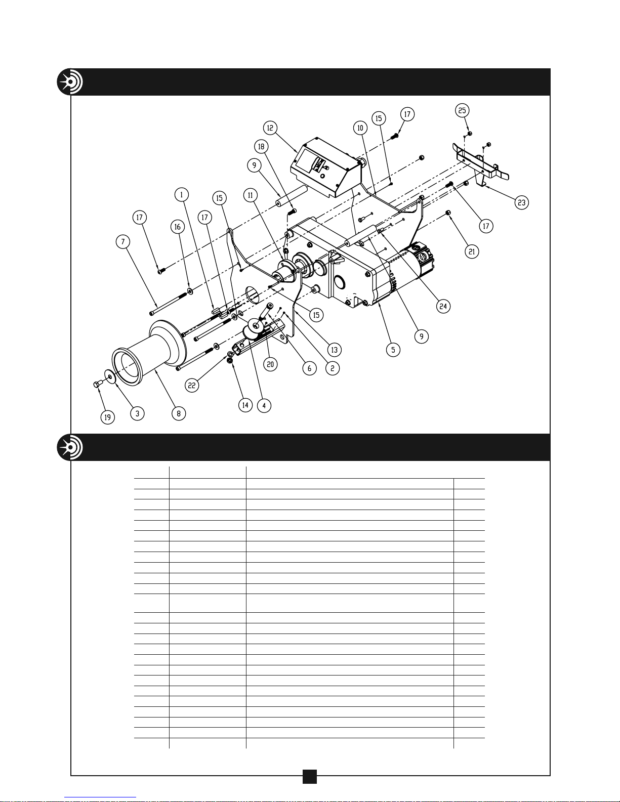
EXPLODED VIEW – MODEL 1450 CABLE PULLER
PARTS LIST – MODEL 1450 CABLE PULLER
ITEM # PART # DESCRIPTION QTY.
1 66-38 KEY-SQUARE (3/8" × 1.25" LG) 2
2 77-044 RIVET, ALUM, BUTTONHEAD (1/8" .08-.120 GRIP) 4
3 88-59 WASHER - 11 GA HRPO ZINC (.630ID × 2.25OD) 1
4 88-18 ROLLER – GUIDE, PULLER 1
5 100-001 MOTOR 1
6 100-022 SCREW – SHOULDER SOCKET (5/8-11 3) 1
7 100-023 SCREW - SOCKET HEAD CAP (3/8-16 × 7") 4
8 100-142 CAPSTAN 1
9 100-146 PULLER HANDLE 2
10 100-148 PULLER PLATE 2 1
11 100-149 CAPSTAN HUB 1
12 100-191
13
14
15
16
17
18
19
20
21
22
23
24
25
100-216 PULLER PLATE 1
281-1J NUT – HEX NYLON INSERT (1/2-13) – THIN 1
452-6A SCREW-SELF DRILL (#8 1/2) 4
506-3 WASHER – FLAT 3/8 (USS) ZINC
610-21 SCREW – BUTTON HEAD CAP (3/8-16 × 1)
750-25 SCREW – SOCKET HEAD CAP (3/8-16 × 1)
8092-2 SCREW – HEX HEAD CAP GR5 ZINC (1/2-13 × 1)
1450-S/N PLATE SERIAL NUMBER PLATE
2-1501-4 NUT-HEX, NYLON INSERT 3/8-16
281-2C WASHER – LOCK, 1/2"
33-706 WELDMENT – WIRE/FOOT SWITCH HOLDER
77-00D1 SCREW – HEX HEAD CAP GR5 ZINC (5/16-18 × 3/4)
2-1301-4 NUT – HEX NYLON INSERT (5/16-18)
ELECTRONICS BOX ASSEMBLY
(See exploded view on pg. 33)
1
4
4
4
1
1
4
1
1
2
2
32
Page 33
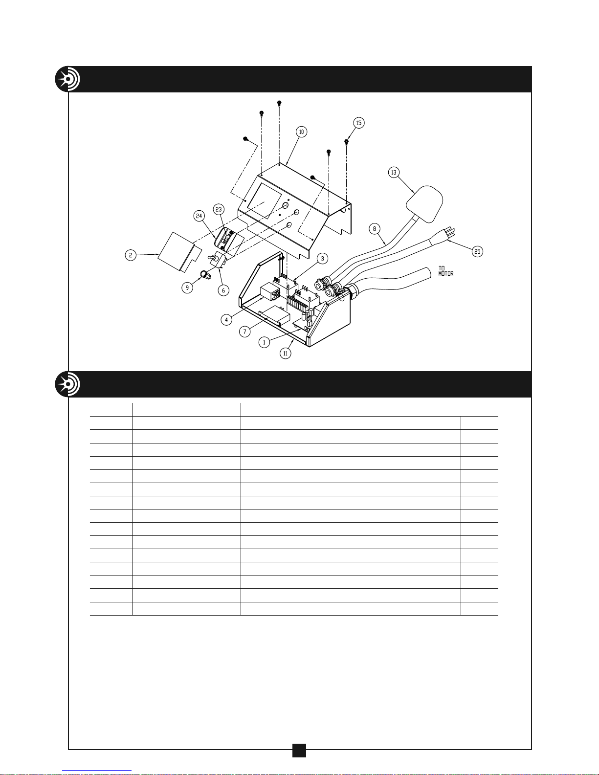
EXPLODED VIEW – MODEL 1450 ELECTRONICS BOX ASSEMBLY
PARTS LIST – MODEL 1450 ELECTRONICS BOX ASSEMBLY
ITEM # PART # DESCRIPTION QTY.
1 100-002 CIRCUIT BOARD 1
2 100-003 METER 1
3 100-004 RELAY 2
4 100-008 RELAY 1
6 100-030 TOGGLE SWITCH 1
7 100-031 TIMER 1
8 100-280 CORD – FOOT SWITCH, 8' 1
9 100-033 LIGHT – READY 1
10 100-189 ELECTRONICS BOX TOP 1
11 100-190 ELECTRONICS BOX BOTTOM 1
13
15 452-6A SCREW – SELF DRILL (#8 X 1/2") 6
23 77-062 ON/OFF SWITCH 1
24 77-063 SWITCH GUARD 1
25 77-068 CORD – POWER 1
33-45 FOOT SWITCH 1
33
Page 34
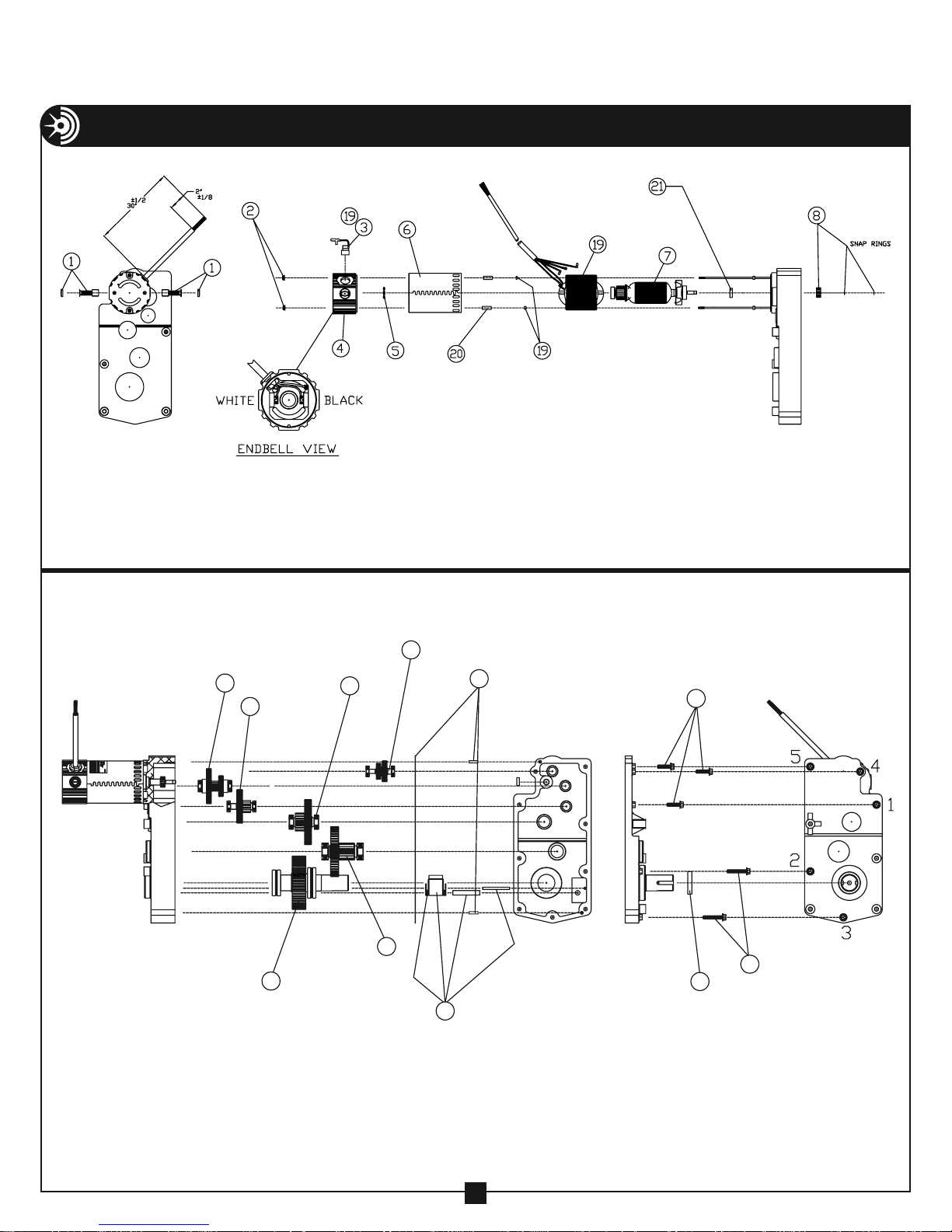
12
16
EXPLODED VIEW – MODEL 1450 CABLE PULLER GEAR MOTOR
9
10
18
11
17
13
14
14
15
34
Page 35
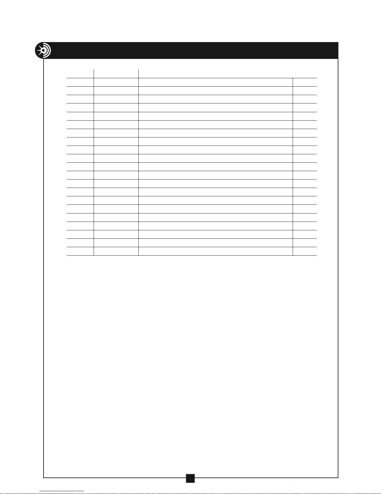
PARTS LIST – MODEL 1450 GEAR MOTOR
ITEM # PART # DESCRIPTION QTY.
1 1000-137 BRUSH ASSEMBLY WITH CAPS 2
2 1000-138 FLANGE NUT 2
3 1000-139 HEYCO STRAIN RELIEF, BLACK, #1287 1
4 1000-140 COMM ENDBELL ASSEMBLY 1
5 1000-141 3 WAVE SPRING (SSB-0138) 1
6 1000-142 MOTOR FRAME 1
7 1000-143 115V ARMATURE AND BEARING ASSEMBLY 1
8 1000-144 1ST STAGE GEAR (PINION) MACHINED/SNAP RINGS (2) 1
9 1000-145 2ND STAGE PINION/GEAR/BEARING ASSEMBLY 1
10
11 1000-147 4TH STAGE GEAR/PINION/BRG ASSEMBLY 1
12
13
14
15
16
17
18
19
20
21
1000-146 3RD STAGE PINION/GEAR/BRG ASSEMBLY 1
1000-148 HIGH SPEED IDLER/BRG ASSEMBLY 1
1000-149 GEARCASE GASKET AND DOWEL PINS (2) 2
1000-150 CAP SCREW KIT — 3/8–16 × 2 1/4" (3) 1 1/2" (2) 1
1000-152 OIL SEAL 1
1000-153 DOWEL PINION/4TH GEAR/BEARING ASSEMBLY
1000-154 OUTPUT PINION/4TH GEAR/BEARING ASSEMBLY
1000-155 OUTPUT SHAFT AND BEARING ASSEMBLY
1000-177 FIELD REPLACEMENT KIT
1000-151 STANDOFF SPACER
50002-24 SEAL
1
1
1
1
2
1
35
Page 36
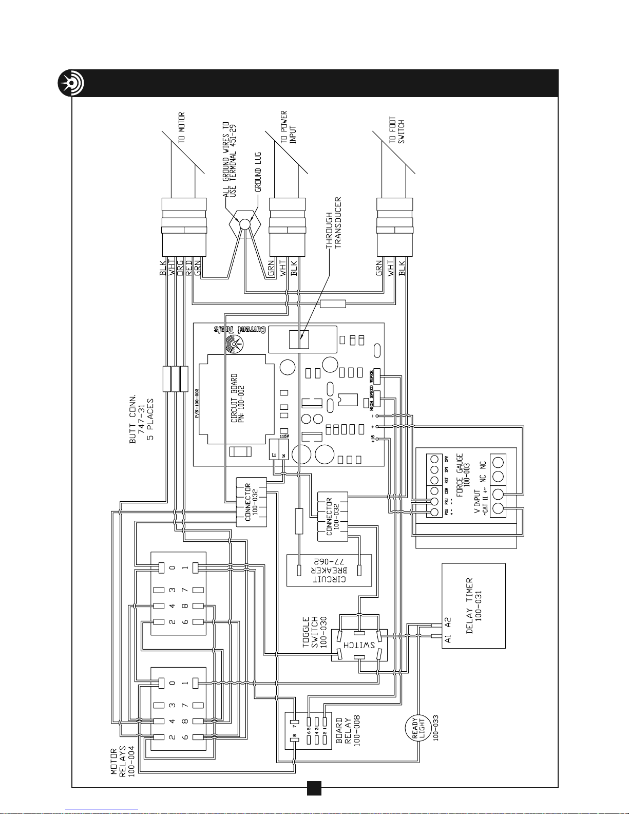
WIRING DIAGRAM – MODEL 1450 CABLE PULLER
36
Page 37
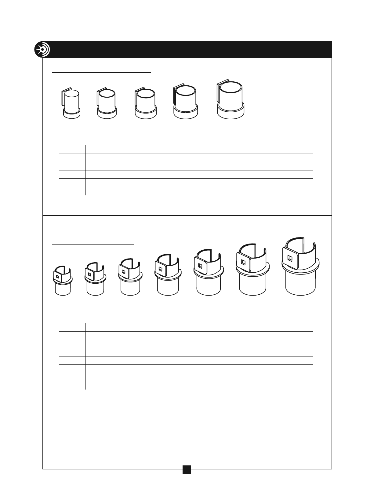
COMPONENT PARTS LISTING
12 34 5 67
SCREW-ON COUPLINGS
12 34 5
ITEM # PART # DESCRIPTION QTY.
1 259 SCREW-ON COUPLING FOR 2" IMC, RIGID CONDUIT optional
2 260 SCREW-ON COUPLING FOR 2 1/2" IMC, RIGID CONDUIT optional
3 261 SCREW-ON COUPLING FOR 3" IMC, RIGID CONDUIT optional
4 262 SCREW-ON COUPLING FOR 3 1/2" IMC, RIGID CONDUIT optional
5
263 SCREW-ON COUPLING FOR 4" IMC, RIGID CONDUIT optional
SLIP-IN COUPLINGS
ITEM # PART # DESCRIPTION QTY.
1 198 SLIP-IN COUPLING FOR 2" EMT, IMC, RIGID CONDUIT 1
2 199 SLIP-IN COUPLING FOR 2 1/2" EMT, IMC, RIGID CONDUIT 1
3 200 SLIP-IN COUPLING FOR 3" EMT, IMC, RIGID CONDUIT 1
4 201 SLIP-IN COUPLING FOR 3 1/2" EMT, IMC, RIGID CONDUIT 1
5
6 230 SLIP-IN COUPLING FOR 5" EMT, IMC, RIGID CONDUIT optional
7
202 SLIP-IN COUPLING FOR 4" EMT, IMC, RIGID CONDUIT 1
255 SLIP-IN COUPLING FOR 6" EMT, IMC, RIGID CONDUIT optional
37
Page 38
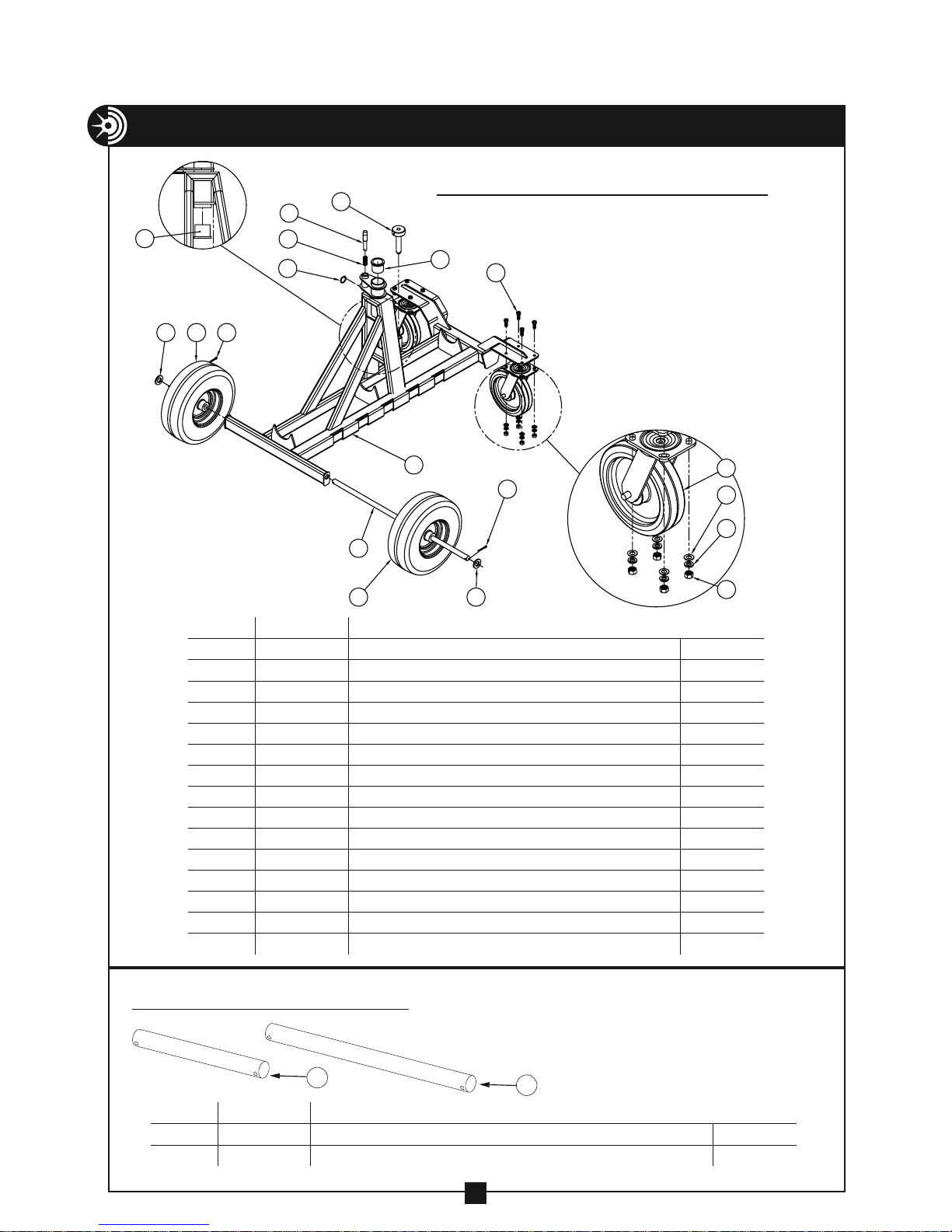
COMPONENT PARTS LISTING — CONTINUED
4
2 1
15
11
14
13
ITEM # PART # DESCRIPTION QTY.
1
2 77-017 WASHER – FLAT 3/4 SAE 2
3 77-429 AXLE 1
4 100-027 BUSHING – BASE 2
5 100-273 FRAME – CARRIAGE 1
6
7 452-28 NUT – HEX, 3/8" 8
8 506-3 WASHER – FLAT, 3/8" 8
9 524-11 SCREW – HX HD CAP, 3/8-16 × 1" 8
10 747-1 CASTER – SWIVEL 2
11 747-4 SPRING 1
12 747-927 SCREW ASSEMBLY – LOCKING 1
13 8091-2 WHEEL 2
14 8099-3 BOOM PIN RING 1
15
77-016 PIN – COTTER, 3/16" × 1 1/4" 2
452-27 WASHER – LOCK 3/8" 8
747-860 PIN – POSITIONING 1
12
13
4
5
3
9
10
1
2
8
6
7
FOUR WHEEL CARRIAGE – 1000
BOOM TUBES – 1850/1860
1
ITEM # PART # DESCRIPTION QTY.
1 1850 3' BOOM TUBE 1
2
1860 4' BOOM TUBE 1
2
38
Page 39
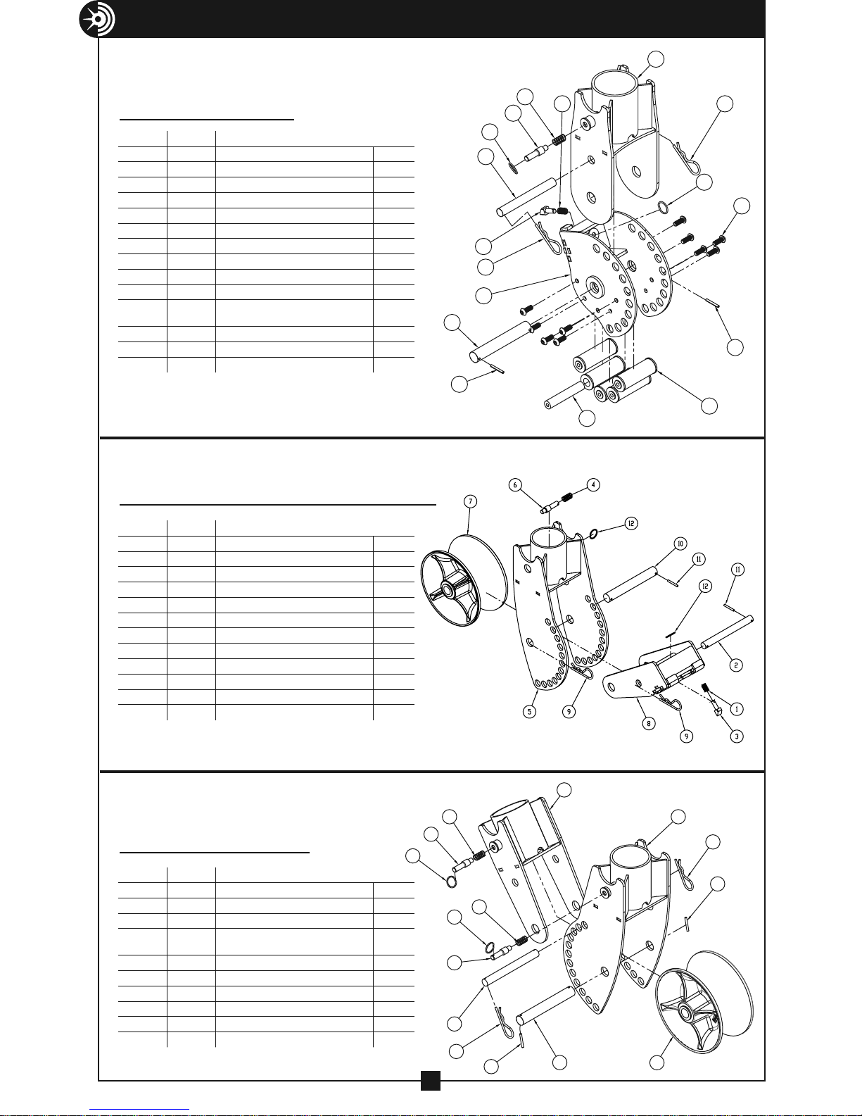
COMPONENT PARTS LISTING — CONTINUED
5
(optional)
NOSE UNIT – 1840
ITEM # PART # DESCRIPTION QTY.
1
33-22 SPRING – COUPLING MOUNT PAWL 1
2 33-485 PAWL – COUPLING MOUNT 1
3 100-011 BOOM PIN SPRING 1
100-170 BOOM PIN 1
4
5 100-172 NOSE UNIT OUTER 1
6 100-173 NOSE UNIT COUPLING ADAPTER 1
7 100-182 NOSE UNIT CUP ADAP ROLLER PIN 5
8 100-203 1 INCH PIN, NOSE UNIT 1
9 100-232 NOSE UNIT ROLLER PIN ASSEMBLY 5
10 406-3 SPRING CLIP 2
11 610-21
12 951TR-10 ANGLE ADJUSTMENT PIN 1
13 8094-2A ROLL PIN 3/16 X 1.5 2
8099-3 BOOM PIN RING 2
14
SCREW-BUTTON HEAD CAP
(3/8-16 X 1)
10
3
4
14
12
2
10
6
8
13
1
7
10
14
11
13
9
NOSE UNIT with Sheave – 1840-S
ITEM # PART # DESCRIPTION QTY.
1
33-22 SPRING – COUPLING MOUNT PAWL 1
2 333-212 ANGLE ADJUSTMENT PIN 1
3 33-485 PAWL – COUPLING MOUNT 1
4 100-011 BOOM PIN SPRING 1
5 100-160 ELBOW UNIT – OUTER 1
6 100-170 BOOM PIN 1
7 100-219 SHEAVE ASSEMBLY 1
8 100-274 NOSE UNIT COUPLING ADAPTER 1
9 406-3 SPRING CLIP 2
10 812-487 PIN – SHEAVE 1
8094-2A ROLL PIN 3/16 X 1.5 2
11
8099-3 BOOM PIN RING 2
12
ELBOW UNIT – 1710
ITEM # PART # DESCRIPTION QTY.
1
100-011 SPRING BOOM PIN 2
2 100-160 ELBOW UNIT OUTER 1
3 100-161 ELBOW UNIT INNER 1
4 333-212
5 100-170 BOOM PIN 2
6 812-487 1 INCH PIN, ELBOW UNIT 1
7 100-219 SHEAVE ASSEMBLY 1
8 406-3 SPRING CLIP 2
9 8094-2A ROLL PIN 3/16 X 1.5 2
8099-3 BOOM PIN RING 2
10
ELBOW UNIT ANGLE
ADJUSTMENT PIN
3
1
5
2
8
10
9
1
10
1
5
4
8
9
6
7
39
Page 40
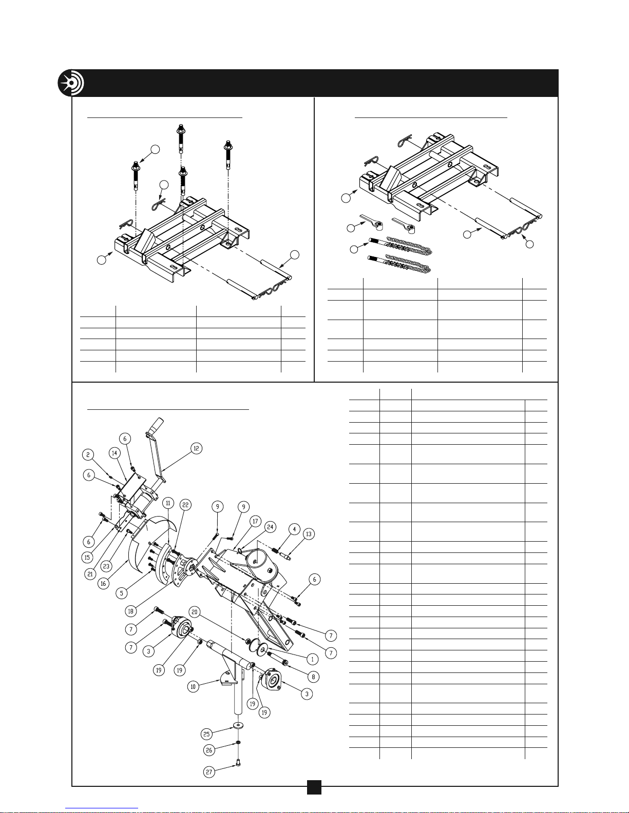
COMPONENT PARTS LISTING — CONTINUED
FLOOR MOUNT – 2280
2
4
1
ITEM # PART # DESCRIPTION QTY.
1 100-231 FLOOR MOUNT FRAME 1
2 8045-3 WEDGE ANCHOR 4
3 333-212 PIN – 3/4" × 7-3/8" 2
4 406-3 SPRING CLIP 4
5
2280-DECALSHEET DECALS (NOT SHOWN) 1
PULLER MOUNT – 1190
CHAIN MOUNT – 2281
1
2
3
3
ITEM # PART # DESCRIPTION QTY.
1 100-231 FLOOR MOUNT FRAME 1
2 88-42
3 88-21L
4 333-212 PIN, 3/4"× 7-3/8" 2
5 406-3 SPRING CLIP 4
2280-DECALSHEET DECALS (NOT SHOWN) 1
6
ITEM # PART # DESCRIPTION QTY.
1
2-1103 ROLLER – SAFETY 1
2 88-39 GREASE FITTING 1
3 100-028 ROTATION T SUPPORT 2
4 100-011 BOOM PIN SPRING 1
5 100-018
6 100-019
7 100-020
8 100-021
9 100-025
10 100-115 ROTATION T 1
11 100-152 GEAR SEGMENT 1
12 100-156
13 100-170 BOOM PIN 1
14 100-192 WORM COVER 1
15 100-210 GEAR HOUSING PLATE 1 1
16 100-217 GEAR HOUSING 1
17 100-265 PULLER MOUNT 1
18 100-267 GEAR HUB AND PLATE 1
19 280-2G NUT-HEX ZINC (1/2-13) 4
20
281-1I NUT-HEX, NYLON INSERT 5/8-11 1
21 450-44A RIVET - BLIND 1/8" 3
22 610-21
23 752-100 3/8 X 3/8 LG SHOULDER BOLT 1
24 8099-3 BOOM PIN RING 1
25
100-297 RETAINING WASHER 1
26 281-2C WASHER – LOCK 1/2" 1
8092-2 SCREW – HX HD CAP (1/2-13 × 1") 1
27
SCREW-BUTTON HEAD SOCKET
SCREW-SOCKET HEAD CAP
SCREW-SOCKET HEAD CAP
SCREW-SHOULDER SOCKET
SCREW-SOCKET HEAD CAP
WORM BOX ASSEMBLY (SEE
EXPLODED VIEW ON PAGE 41)
SCREW-BUTTON HEAD CAP
4
CHAIN MOUNT HANDLE
ASSEMBLY
CHAIN MOUNT CHAIN
ASSEMBLY
(5/16-18 × 3/4)
(3/8-16 × 3/4)
(1/2-13 × 1.5)
(3/4-10 × 3.25)
(5/16-18 × 1.125)
(3/8-16 × 1)
5
2
2
5
10
4
1
2
1
4
40
Page 41
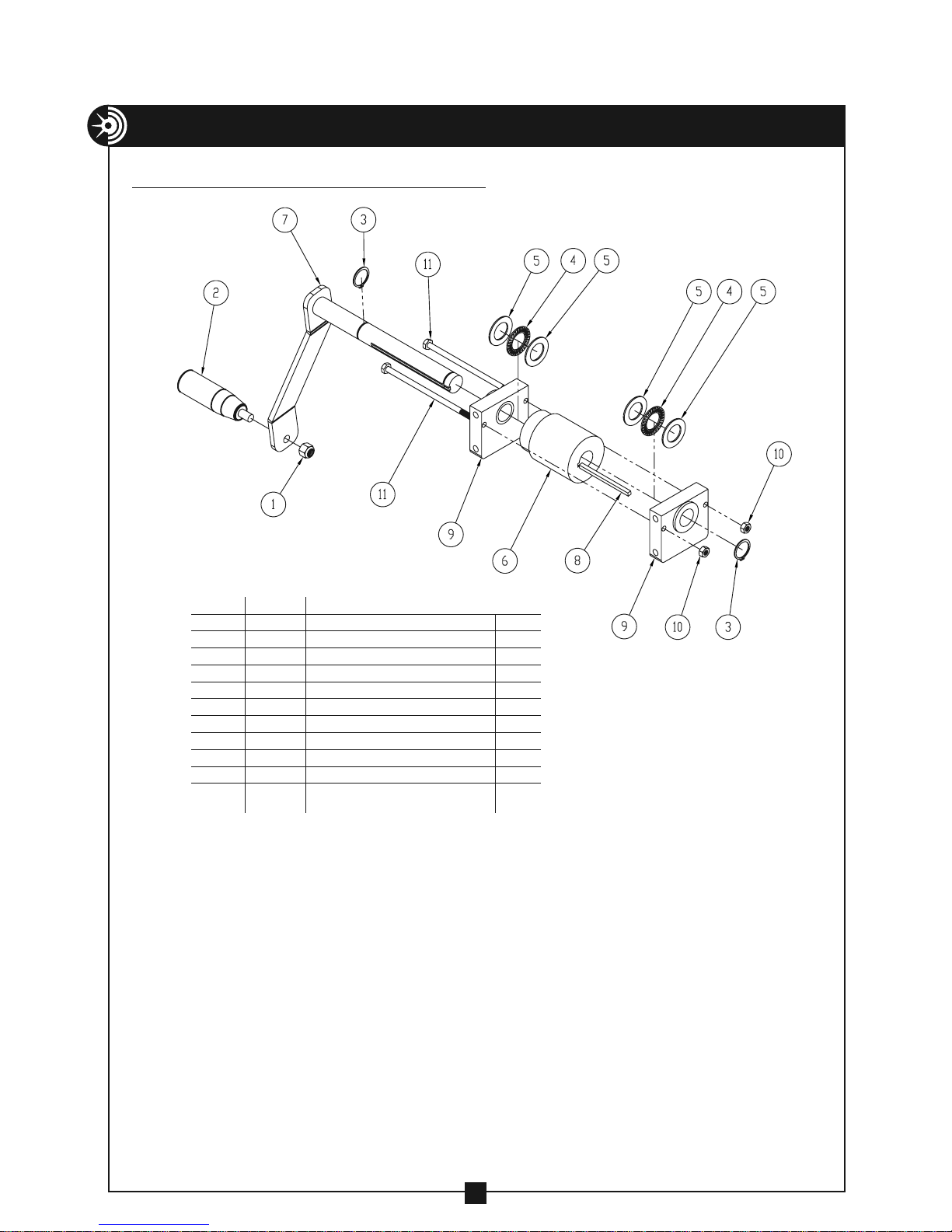
COMPONENT PARTS LISTING — CONTINUED
WORM BOX ASSEMBLY – 100-156
ITEM # PART # DESCRIPTION QTY.
1
2-1504-4 NUT-HEX NYLON INSERT (3/8-16) 1
2 100-006 PLASTIC HANDLE 1
3 100-026 7/8 RETAINING RING – EXTERNAL 2
4 100-012 THRUST BEARING 2
5 100-013 THRUST RACE 4
100-016 WORM GEAR 1
6
100-233 WORM HANDLE WELDMENT 1
7
8 100-269 KEYSTOCK 3/16" × 3.125" 1
9 100-270 WORM BOX PLATE AND BUSHING 2
10 9518SR-12 NUT – HEX, NYLON INSERT (1/4-20) 2
95024RA-7
11
SCREW – HEX HEAD CAP GR5 ZINC
(1/4-20 × 5.5)
2
41
 Loading...