

Current Tools 8845, 88 Series, Mantis 8885 Series, 8085, Mantis 8890 Series Operating, Maintenance, Safety And Parts Manual
...Page 1

Model 88 Series Cable Puller
8,000 lb. Maximum Pulling Force
and
Model 8845 Cable Pulling Package
Operating, Maintenance, Safety
and Parts Manual
10/14 REV. 5
ead and understand this material before operating or
R
servicing the Cable Puller or any of component Cable Pulling
Package. Failure to understand how to safely operate and
service these units may result in serious injury or death.
his manual is free of charge. All personnel who operate the Cable Puller or any component of the
T
Cable Pulling Package should have a copy of this manual and read and understand its contents. To
request a copy of this manual or replacement safety decals, or for technical assistance, call or
write to the address below. All information, specifications and product designs may change due to
design improvements or updates and are subject to change without notice. Current Tools does not
assume any liability for damages resulting from misuse or incorrect application of its products.
CURRENT TOOLS • P. O. BOX 17026 GREENVILLE, SC 29606
800.230.5421 or 864.721.4230 • FAX 864.721.4232
www.currenttools.com
Page 2
TABLE OF CONTENTS
Safety Alerts . . . . . . . . . . . . . . . . . . . . . . . . . . . . . . . . . . . . . . . . . 3
Important Safety Information . . . . . . . . . . . . . . . . . . . . . . . . . . 4-7
Specifications . . . . . . . . . . . . . . . . . . . . . . . . . . . . . . . . . . . . . . . . 7
Features . . . . . . . . . . . . . . . . . . . . . . . . . . . . . . . . . . . . . . . . . . . . 7, 8
Components Listing . . . . . . . . . . . . . . . . . . . . . . . . . . . . . . . . . . . 9
Cable Pulling Basics . . . . . . . . . . . . . . . . . . . . . . . . . . . . . . . . 10-13
Model 88 Cable Puller and Accessories
Power Requirements
Force Gauge
Mounting Chain Installation
Floor Mount . . . . . . . . . . . . . . . . . . . . . . . . . . . . . . . . . . . . . . 14, 15
Safety Information
Installation Instructions
Operating Instructions . . . . . . . . . . . . . . . . . . . . . . . . . . . . . .16-19
Rope Set-Up
Pulling Operation
Common Set-Ups . . . . . . . . . . . . . . . . . . . . . . . . . . . . . . . . . . . . 20
Tandem Pulling . . . . . . . . . . . . . . . . . . . . . . . . . . . . . . . . . . . . . . 21
Maintenance . . . . . . . . . . . . . . . . . . . . . . . . . . . . . . . . . . . . . . . . 21
Lubrication
Inspection
Exploded View – Model 88 Cable Puller . . . . . . . . . . . . . . . . . . 22
Parts List – Model 88 Cable Puller . . . . . . . . . . . . . . . . . . . . . . . 23
Exploded View – Model 88 Cable Puller Motor . . . . . . . . . . . . 24
Parts List – Part #88-44 Cable Puller Motor . . . . . . . . . . . . . . . 25
Wiring Schematic – Model 88 Cable Puller . . . . . . . . . . . . . . . 26
Wiring Drawing – Model 88 Cable Puller . . . . . . . . . . . . . . . . . 26
2
Page 3

jury
.
W
G
jury
.
ON
jury
.
G
R
SAFETY ALERTS
3
THIS SAFETY SYMBOL is used to call your attention to instructions
that concern your personal safety. It means: ATTENTION! BE AWARE!
THIS IS AN IMPORTANT SAFETY INSTRUCTION!
Read, understand, and follow these safety instructions. Failure to follow
these safety instructions may result in injury or death.
Safety Alert
Symbol
DAN
Immediate hazards which, if not avoided, WILL result in serious personal
in
or death
E
ARNIN
Hazards or unsafe practices which, if not avoided, COULD result in serious
personal in
or death
UTI
Hazards or unsafe practices which, if not avoided, COULD result in minor
personal in
or property damage
Page 4
WARNING
WARNING
WARNING
WARNING
WARNING
WARNING
WARNING
WARNING
WARNING
DANGER
DANGER
RETAIN SAFETY INFORMATION
4
Do NOT operate cable puller in wet or damp locations.
Do NOT expose to rain.
Do NOT operate in an explosive atmosphere.
Do NOT use cable puller as a hoist or for lifting, supporting
or transporting people or loads. Use only for its intended
purpose as a cable puller.
Do NOT wrap rope around any body parts. Do NOT wrap
rope around wrists.
ALWAYS keep rope away from operator’s feet.
Do NOT exceed load rating of cable puller, rope, or accessories.
ALWAYS inspect rope before each use.
ALWAYS disconnect cable puller before servicing.
ALWAYS plug the Model 88 Cable Puller into a grounded
receptacle with a 15 amp GFCI protected circuit. Do NOT
modify the plug provided with the Model 88 Cable Puller.
ALWAYS inspect the structural integrity of any supports,
conduit, anchoring system etc. that will hold the cable puller
during the pull. These supports should be able to withstand
the maximum pulling force of the cable puller plus a safety
factor of 3:1.
Example: 8,00 0 lb. puller should be anchored
to a support that can withstand 24,000 lbs. of pull
.
IMPORTANT SAFETY INFORMATION
G
pp
.
p
.
OK
E
This manual should be read and understood by all personnel who operate or service
this Cable Puller or any component of the Cable Pulling Package. Failure to understand
how to operate and service this equipment could result in serious injury or death. This
equipment should only be operated and serviced by qualified personnel.
ARNIN
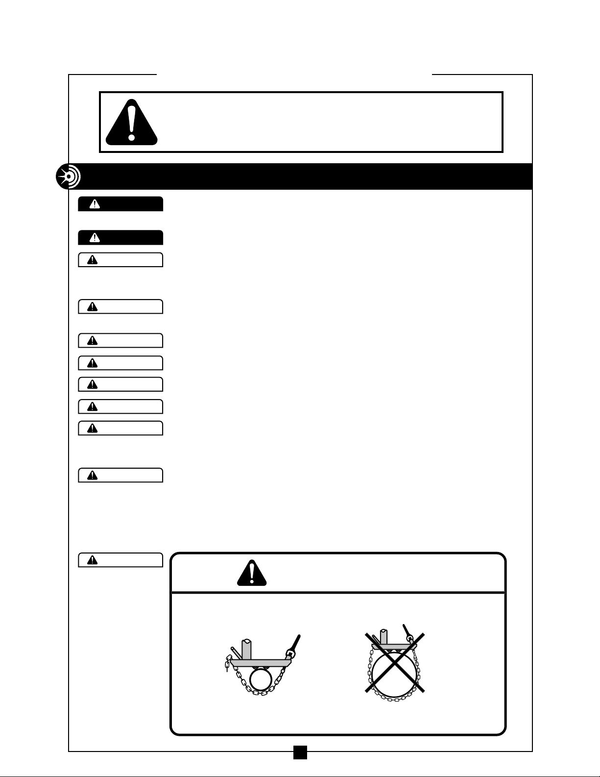
ALWAYS insure cable puller is properly secured before operating.
ALWAYS attach to su
See mounting chain installation section of this manual for proper mounting
of cable
uller and tie-down chain installation
orts that are at least 2" and not more than the 10" wide
TOO WID
Page 5
5
WARNING
WARNING
WARNING
WARNING
WARNING
WARNING
WARNING
WARNING
WARNING
WARNING
Pulling Rope should be the only thing to contact the capstan.
NEVER let swivels, grips, etc. come in contact with the capstan.
Keep as much rope confined in conduit as possible. This will
help prevent injury should the rope break and whip violently.
Rope must ALWAYS be pulled over a r
otating sheave. If
a sheave does not rotate, turn cable puller off immediately
and determine problem before continuing the pull.
This cable puller is equipped with an anti-reversing pawl.
The pawl will make a clicking sound when the capstan is
rotating. If you can not hear the clicking sound as the capstan
rotates, immediately turn the cable puller off and do not
use until repaired.
ONL
Y use 3/4” or larger double-braided composite pulling
rope with an average breaking strength of 26,000 lbs.
NEVER allow the rope to slip on a rotating capstan for more
than a couple of seconds. The rope will wear in that spot and
the rope could break under pressure. If you need to stop the
pull, turn the cable puller off and tie the rope off to hold it
in place until you restart your pull.
Keep all body parts, hair, loose clothing, etc. away from rotating
parts and pinch points. Keep hands away from capstan.
NEVER allow the rope to overlap on the capstan. If this condition
begins to occur, immediately release the tailing force on the rope
so that the rope can feed back toward the conduit or cable tray.
If this does not remedy the overlap, turn off the cable puller
immediately.
There is
no known solution for
rope overlap.
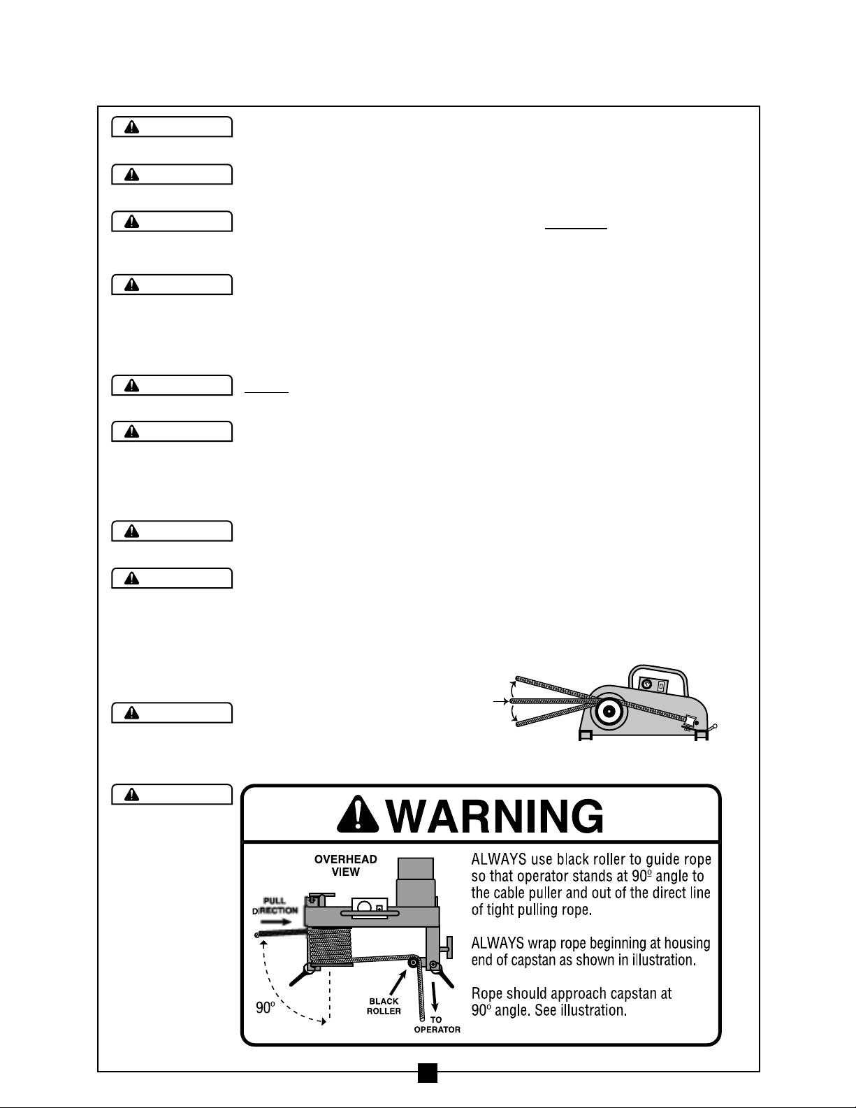
Rope should approach
capstan as shown in
Figure 1.
Figure 1
IMPORTANT SAFETY INFORMATION continued . . .
MAXIMUM
10
˚
PULL
DIRECTION
MAXIMUM
10
˚
Page 6
Some components of the cable pulling package exceed 50 lbs.
and will require more than one person to lift, transport, and
assemble.
ALWAYS inspect pins to be sure they are fully inserted through
holes and have spring clips properly attached.Do NOT substitute
any other object for factory supplied pins.
Do NOT mount the Model 88 Cable Puller to square columns
or I-beams. The mounting chains will not tighten properly on
these structures.
The ONLY approved method to secure the Model 88 Cable Puller
is with the 2 mounting chains provided. Do NOT attempt to use
any other object to secure the cable puller.
Inspect mounting chains for wear before each installation.
NEVER alter the mounting chains or handle.
When making a vertical cable pull, keep the area underneath
the cable pull clear of all personnel.
Do NOT alter this cable puller. Doing so will void the warranty.
Guards and safety features are provided for you r pr otection.
Do NOT use an extension cord longer than 100 ft. Extension
cord should be a minimum of 12 gauge wire with ground.
6
WARNING
WARNING
WARNING
WARNING
WARNING
WARNING
WARNING
CAUTION
CAUTION
IMPORTANT SAFETY INFORMATION continued . . .
A
B
O
OK
g
y
g
g
G
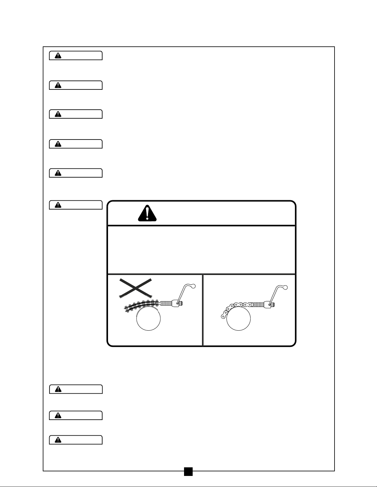
Figure 2BFigure 2A
ARNIN
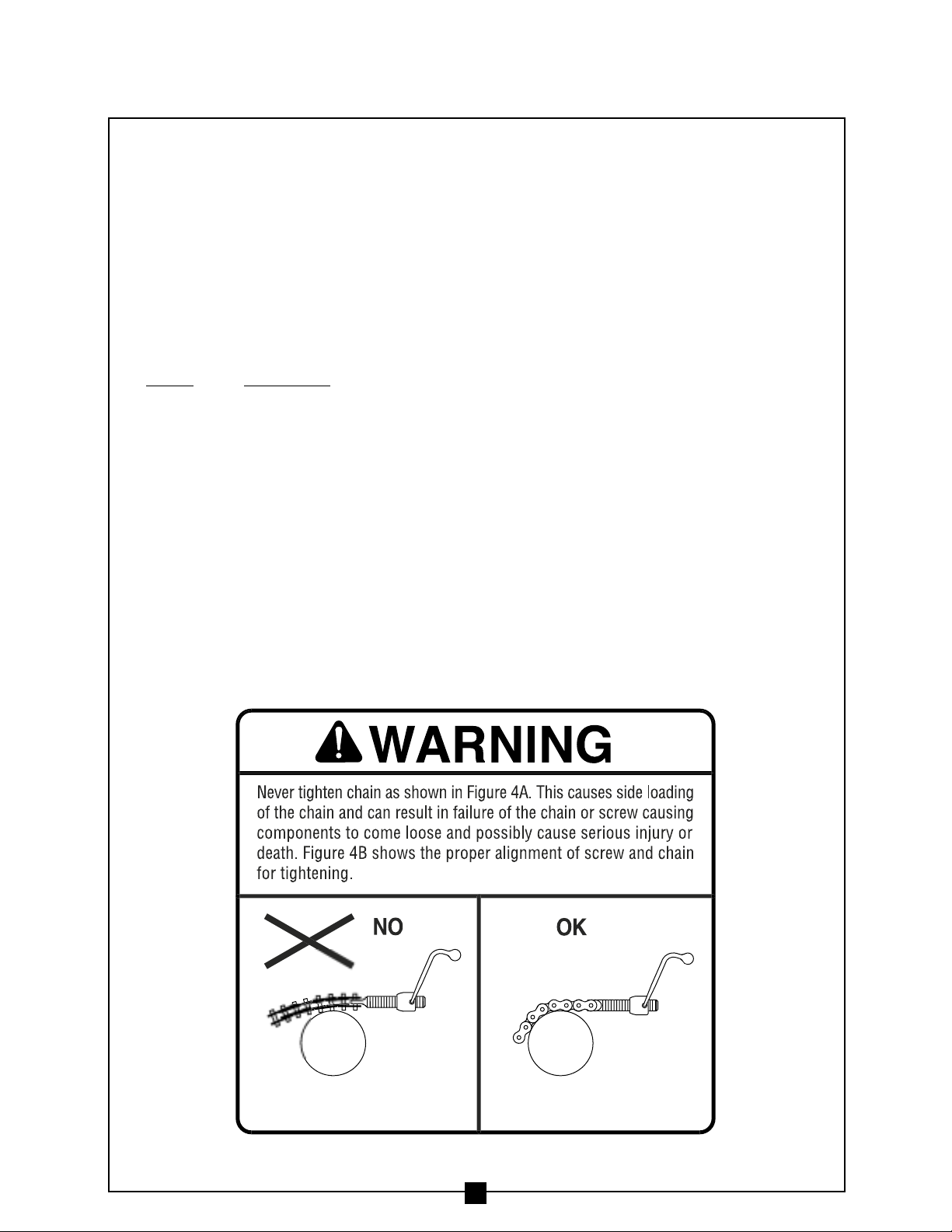
Never tighten chain as shown in Figure 2A. This causes side loadin
of the chain and can result in failure of the chain or screw causing
components to come loose and possibl
death. Fi
for ti
ure 2B shows the proper alignment of screw and chain
htening.
cause serious injury or
N
FIGURE 2
FIGURE 2
Page 7
CAUTION
CAUTION
CAUTION
Wear eye protection when operating cable puller.
Inspect all components of the pulling system before begin-
ning any cable pull. This includes the cable puller and any
accessories ( sheaves, swivels. etc. ) Replace any worn or
defective components.
Be careful during assembly and disassembly of the pulling
system components. Have control of components before
removing any pins.
7
IMPORTANT SAFETY INFORMATION continued . . .
SPECIFICATIONS — Model 88 Cable Puller
Model No. 88 Cable Puller
width – 20 1/2”
length – 24 3/4”
height – 16”
weight – 101 lbs. (includes two mounting chains)
maximum pulling force – 8,000 lbs.
speeds (approx.) no load – 16 ft/min.
4,000 lbs. – 9 ft/min.
6,000 lbs. – 7 ft/min.
motor – 120 volts AC, 60 hertz, 15 amps
FEATURES
• Heavy duty all welded unitized steel frame
• Permanently mounted force gauge allows operator to monitor the pulling force
• Circuit breaker on/off switch — helps protect motor
• Safety pawl on capstan sprocket to prevent reverse rotation
• Tapered capstan to help avoid rope overlap
• Simple design provides for easy maintenance — only one guard covers all
sprockets and chains
• Tailing rope safety roller for operator safety — lets operator stand out of the
direct line of tight pulling rope
• Three handles for carrying or positioning puller
• Simple electrical system for easy maintenance
Page 8

CAPSTAN
C
N
D
E
CE
E
T
CH
OR
R
CORD
E
G
S
Y
R
FEATURES continued . . .
8
Figure 3
HAI
GUAR
AFET
ROLLE
HANDL
FOR
GAUG
OFF/ON CIRCUI
BREAKER SWIT
MOT
MOUNTIN
HAIN
POWE
T-HANDL
Page 9

CAT. NO. KEY DESCRIPTION
PULLER
PULLER WITH FLOOR MOUNT WT.
ONLY
88 8845
88 A Cable puller with chains 1 1 101
8045
B floor mount 116
COMPONENTS LISTING
9
Cable Puller Package
A
B
Page 10

CABLE PULLING BASICS
Model 88 Cable Puller and Accessories
The Model 88 Cable Puller has a maximum pulling force of 8,000 lbs.
Therefore, all of the accessories used to make a cable pull with this unit
must
be rated to meet or exceed the forces generated. This includes, but
is not limited to pulling rope, sheaves, swivels, grips, etc. Be aware that
the pulling force on a sheave and its anchoring system can be as great as
twice the pulling force generated by the cable puller.
Power Requirements
The Model 88 Cable Puller motor is rated at 120 volt – 60 hz – 15 amps.
10
p
.
,
.
G
.
ON
G
y
)
.
ON
ARNIN
Do NOT exceed load rating of cable puller, rope, or accessories.
UTI
Inspect all components of the pulling system before beginning any cable pulling.
This includes the cable puller and an
Replace any worn or defective components
accessories sheaves, swivels. etc.
ARNIN
ALWAYS plug the Model 88 Cable Puller into a grounded receptacle with
a 15 am
DO NOT modify the plug provided with the Model 88 Cable Puller. If needed
have a 15 amp GFCI receptacle installed by a qualified electrician
GFCI protected circuit
UTI
If an extension cord is used, it should be a minimum of 12 gauge wire with
round and a maximum length of 100 ft
Page 11
11
CABLE PULLING BASICS continued . . .
Force Gauge
The Model 88 Cable Puller is equipped with an integral force gauge.
To calibrate the force gauge, run the puller for 1 minute with no load.
While the puller is running (with no load), use adjustment screw on face
of force gauge to set needle to zero pounds of force.
The operator should always monitor the force gauge throughout the entire
cable pull. The force gauge has 3 color sections to help you identify operating
conditions. These sections are:
Color
Condition
Green Puller can be run continuously
Yellow 50% duty cycle; 15 minutes on / 15 minutes off
Red Overload Condition – Do NOT operate puller
Correct overload condition or set up a tandem pull
(See page 21. )
Mounting Chain Installation
The Model 88 Cable Puller is designed to be mounted using the two mounting
chains provided. The handles on the chains should provide sufficient leverage
to tighten the chains securely. No other tools are needed. Be sure to check the
mounting chains for kinks and twists before you tighten them. See Warning
below for proper mounting chain installation.
Figure 4BFigure 4A
Page 12

pp
.
E
G
12
Figure 5
A– Loosen the mounting chain
handle so that only 3 or 4 threads
remain engaged.
B– Wrap the chain around the
floor mount, conduit or structural
support sufficient to handle
the pulling forces.
C– Pull the loose end of the mounting
chain tight and hook the closest
chain link into the recessed area.
D– Tighten the chain handle.
Repeat this process for second
mounting chain.
G
CABLE PULLING BASICS continued . . .
ARNIN
Be sure threads do not bottom out before chain becomes tight.
DAN
ALWAYS insure cable puller is properly secured before operating.
ALWAYS attach to su
orts that are at least 2" and not more than the 10" wide
ER
TOO WID
Page 13

13
CABLE PULLING BASICS continued . . .
y
g
y
f
.
G
y
.
G
g
y
.
.
.
G
ARNIN
The only approved method to secure the Model 88 cable puller is with
the 2 mountin
attempt to use an
Inspect mounting chains for wear before each installation
. NEVER alter the mounting chains or handle
chains provided with the Model 88 cable Puller. Do NOT
other object to secure the puller
ARNIN
ALWAYS inspect the structural integrity of any supports, conduit, anchoring
s
stem etc. that will hold the cable puller during the pull. These supports
should be able to withstand the maximum pullin
plus a safet
a support that can withstand 24,000 lbs. o
factor of 3:1. Example: 8,000 lb. puller should be anchored to
force of the cable puller
pull
ARNIN
Do NOT mount the Model 88 Cable Puller to square columns or I-Beams.
The mounting chains will not tighten properl
on these structures
Page 14

FLOOR MOUNT
The Model 8045 Floor Mount is made to fit the Current Tools Model 88
Cable Puller. The floor mount is to be mounted only to a concrete floor
using the method described below.
Safety Information
1. ALWAYS mount to a smooth, flat
concrete floor with a minimum
3000 psi rating.
2. Mount only to a concrete floor.
NEVER
mount to cinder blocks, brick, etc.
3. Wedge anchors must be at least 12” away from edge of concrete.
4. ALWAYS use new anchors. NEVER REUSE ANCHORS.
5. Use only 5/8” x 6” wedge anchors or equivalent with a tension
and shear rating of 2,500 lbs. (Current Tools part #8045-3)
6. ALWAYS wear eye protection when installing anchors.
14
CAUTION
S
y
.
G
Figure 6A
Figure 6B
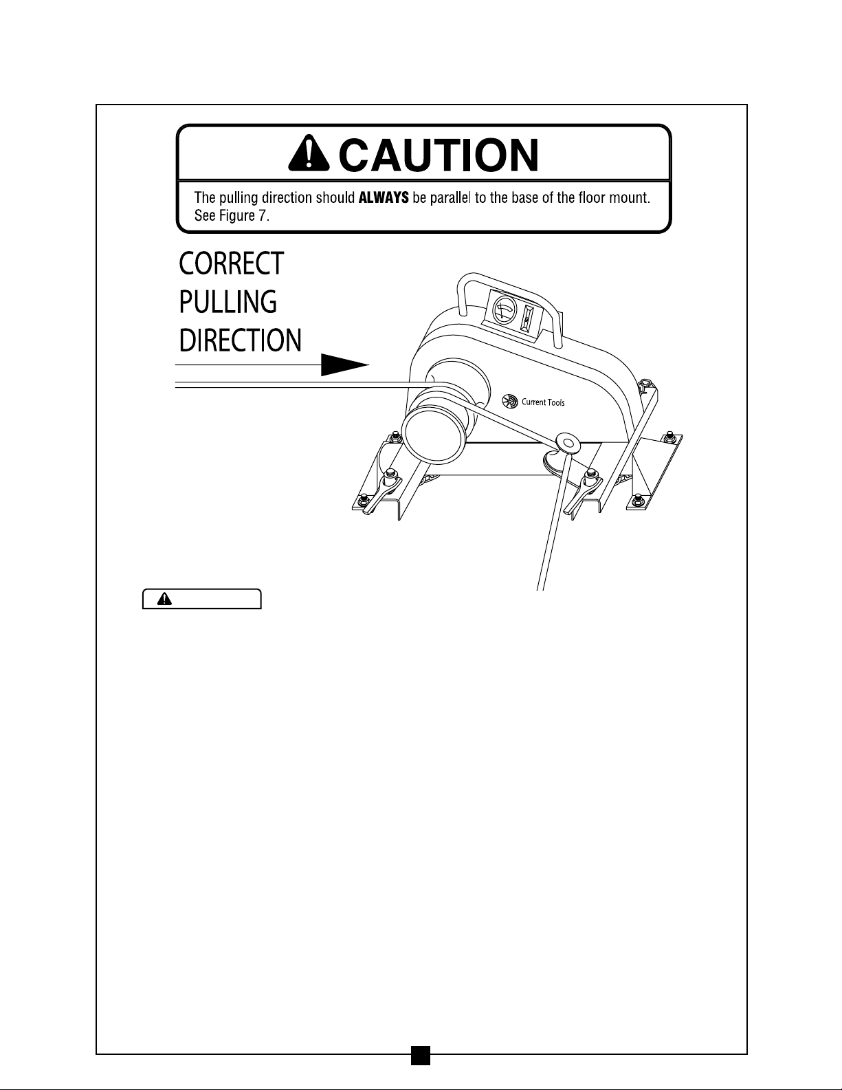
ALWAY
possibilit
place the floor mount close to the conduit. This will reduce the
of injury should the rope break. See Figure 6B
place close to conduit
ARNIN
Page 15
CAUTION
15
FLOOR MOUNT continued . . .
Installation Instructions
1. Wear safety glasses.
2. Follow the safety instructions provided by the drill manufacturer.
3. Use only 5/8” diameter solid carbide tipped bits that meet ANSI B94-12.
4. Using the floor mount as a template, drill four 5/8” holes a minimum
of 6” deep but not closer than 1 1/4” to the bottom (opposite surface) of
the concrete. Be sure to drill the holes perpendicular to the work surface
and do not ream the holes or let the drill bit wobble.
5. Clean the holes with compressed air and a wire brush. Clean holes are
necessary for proper performance.
6. Assemble the washer and nut on the anchor so the top of the nut is flush
with the top of the anchor.
7. Next, drive the 4 wedge anchors through the 4 floor mount holes and into
the concrete holes making sure the nut and washer rests solidly against
the floor mount.
8. Tighten the anchors with a torque wrench to 75–90 ft. lbs.
Note: If anchor spins, pull up on the anchor using the claw end of hammer
and then torque. If spinning still occurs, Do NOT use this location; reposition
the floor mount and repeat this installation procedure.
9. Place the Model 88 Cable Puller so that the “V” positioning units on the
bottom of the puller legs straddle the floor mount. Mount puller to the
floor mount using the mounting chain installation procedure found on
pages 11, 12, & 13 of this manual.
Figure 7
Page 16
Rope Set-Up
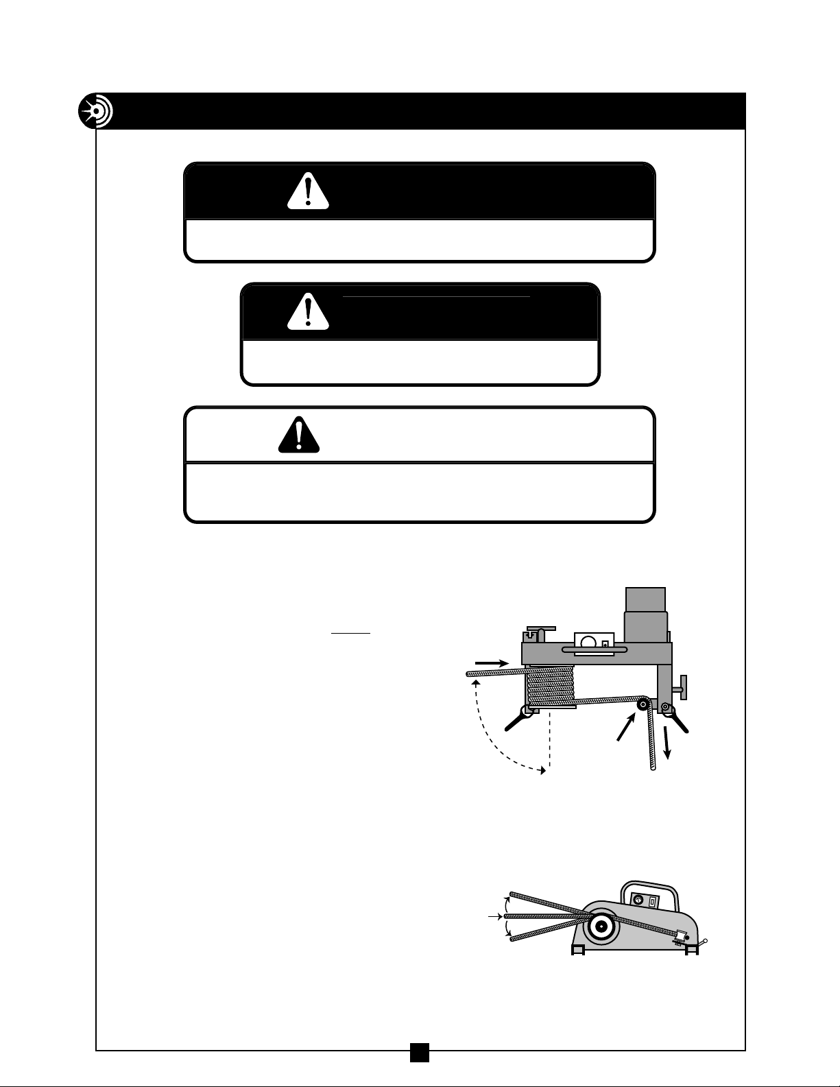
As shown in the overhead view,
Figure 8A, the pulling rope must
approach the capstan at a 90º angle.
This will help avoid rope overlap.
Make several wraps of the pulling
rope around the capstan, beginning
at the housing end of the capstan.
See Figure 8A.
Next, guide the pulling rope around
the black safety roller as shown in
Figure 8A. This will enable the operator
to stand at a 90º angle to the cable
puller and out of the direct line of
tight pulling rope.
Also note the pulling rope should
approach the capstan as indicated
in
Figure 8B.
16
Figure 8B
Figure 8A
OPERATING INSTRUCTIONS — Model 88 Cable Puller
G
.
G
y
G
DAN
Do NOT operate cable puller in wet or damp locations. Do NOT expose to rain.
DAN
Do NOT operate in an explosive atmosphere
ARNIN
Do NOT use cable puller as a hoist or for lifting, supporting or transporting
people or loads. Use onl
for its intended purpose as a cable puller.
ER
ER
90º
MAXIMUM
10
˚
PULL
DIRECTION
MAXIMUM
10
˚
BLACK
ROLLER
TO
OPERATOR
Page 17

17
Pulling Operation
1. Be sure the cable puller power switch is in the off position.
2. Operator should monitor the force gauge throughout the entire cable pull.
3. Hold the tailing end of the pulling rope and pull slightly. Turn the cable
puller
on.
Note: The tailing rope is that portion of the pulling rope that has
passed the capstan and is now excess to the pull. By pulling on the
tailing rope the operator can control and vary the pulling force. It
should require no more than 10 lbs. of tailing force by the operator
to engage the pulling rope on the capstan. If the rope slips on the
capstan, turn the puller off and add an additional wrap of rope
around the capstan. Also note that with the tailing force at a constant pull, each additional wrap of rope around the capstan will
approximately double the pulling force of the cable puller.
g
.
.
.
.
G
th
.
.
G
.
ON
OPERATING INSTRUCTIONS continued . . .
ARNIN
ALWAYS use black roller to guide rope so that operator stands at 90
cable puller and out of the direct line of ti
ALWAYS wrap rope beginning at housing end of capstan as shown in Figure 8A
Rope must approach capstan at a 90o angle. See Figure 8A
Rope should approach capstan as shown in Figure 8B
ht pulling rope. See Figure 8A
angle to the
ARNIN
Rope Requirements: Use only 3/4" or larger double braided composite pulling rope
wi
an average breaking strength of 26,000 lbs
Be sure to inspect rope for damage before each cable pull
UTI
Wear eye protection when operating cable puller
Page 18
18
4. As the rope is tailed it should mound on the floor between the
operator and the cable puller.
5. Turn the cable puller switch to the
off position when the pull is completed.
Note: The Model 88 Cable Puller is equipped with a circuit breaker
switch. If the amperage rating of the breaker is exceeded the puller
will stop. Before restarting the pull, allow the motor to cool and
determine the cause for the overload condition. Correct before
restarting the pull.
g
y
.
G
,
y
G
.
p
.
G
y
y
.
.
G
OPERATING INSTRUCTIONS continued . . .
ARNIN
NEVER allow the rope to slip on a rotating capstan for more than a couple of seconds
The rope will wear in that spot and the rope could break under pressure. If you need
to sto
the pull, turn the cable puller off and tie the rope off to hold it in place until
ou restart your pull
ARNIN
This cable puller is equipped with an anti-reversing pawl. The pawl will make a clickin
sound when the capstan is rotating. if you can not hear the clicking sound as the
capstan rotates, immediatel
turn the cable puller off and do not use until repaired
ARNIN
NEVER allow the rope to overlap on the capstan. If this condition begins to occur
immediately release the tailing force on the rope so that the rope can feed back toward
he conduit or cable tray. If this does not remedy the overlap, turn off the cable puller
immediatel
. There is no known solution for rope overlap.
ARNIN
Keep all body parts, hair, loose clothing, etc. away from rotating parts and pinch
points. Keep hands awa
Do NOT wrap rope around an
ALWAYS keep the tailing rope away from the operator
from capstan.
body parts. Do NOT wrap rope around wrists
feet
Page 19

19
G
y
G
y
G
p
G
y
y
y
p.
G
OPERATING INSTRUCTIONS continued . . .
ARNIN
Rope must ALWAYS be pulled over a rotating sheave. If a sheave does not rotate, turn
cable puller off immediatel
and determine the problem before continuing the pull.
ARNIN
Pulling Rope should be the only thing to contact the capstan. NEVER let swivels, grips,
tc. come in contact with the capstan.
ARNIN
NEVER allow the rope to overlap on the capstan. If this condition begins to occur,
immediatel
toward the conduit or cable tra
cable puller immediatel
release the tailing force on the rope so that the rope can feed back
. If this does not remedy the overlap, turn off the
. There is no known solution for rope overla
ARNIN
Keep as much rope confined in the conduit as possible. This will help prevent injur
should the rope break and whip violently.
ARNIN
When making a vertical cable pull, keep the area underneath the cable pull clear
of all
ersonnel.
Page 20

COMMON SET-UPS
NOTE: When using Manhole Sheave,
always refer to Model 308/310/312 Manhole
Sheave instruction sheet. For a FREE copy
of this instruction sheet, call Current Tools
at 800-230-5421 or write to Current Tools;
PO Box 17026; Greenville, SC 29606
20
Page 21

TANDEM PULLING
If the amount of pulling force required to make a pull exceeds the load rating
for a single cable puller, two cable pullers may be used in tandem to make the
pull. See Figure 9 below. Be sure to use a separate rope and set of accessories
for each cable puller. Each set of rope and accessories should meet or exceed
each cable pullers maximum pulling force.
21
Figure 9
MAINTENANCE
Capstan
Replace the capstan if it is grooved more than 1/16” deep.
Lubrication
Front and Rear Drive Chains — Lubricate the inside of both drive chains every
20 hours of operation with 90 wt. gear oil.
Capstan Shaft, Rear Drive Shaft and Ratchet Pawl — Grease every 10 hours with a
good quality multi-purpose (M.P.) grease. These grease fittings are located on the
side of the cable puller.
See item #39 on Model 88 Cable Puller exploded view.
Inspection
Important: After the first 5 hours of operation remove the cover and
inspect both chain tensioners. Adjust as needed.
Front and Rear Chain Inspection — Every 40 hours of operation the front and rear
drive chains should be removed and inspected for excessive wear or binding.
Motor Brushes – Inspect the two motor brushes every 30 hours. Replace
if less than 3/8” long. Always replace both brushes at the same time.
g.
G
y
ON
ARNIN
Unplug the cable puller before servicin
UTI
Do NOT alter this cable puller. Doing so will void the warranty. Guards and
safet
features are provided for your protection.
Page 22

EXPLODED VIEW – MODEL 88 CABLE PULLER
52
44
38
34
21
28
54
28
31
29
9
30
29
27
51
32
27
49
50
INCLUDED
WITH ITEM 45
35
39
40
41
38
46
47
48
39
45
2
39
1
37
53
5
33
22
42
24
23
25
19
52
20
6
4
7
3
26
18
53
10
8
12
13
11
51
15
17
16
16
17
14
51
32
51
32
22
Page 23

PARTS LIST – MODEL 88 CABLE PULLER
ITEM # PARTS DESCRIPTION QTY PART #
1 PULLER HOUSING 1 88-53
2 CHAIN GUARD 1 88-32
3 FLAT HEAD SOCKET CAP SCREW 5 88-1
4 #60 SPROCKET 1 88-54
5 CAPSTAN SPROCKET BOLT 4 88-55
6 STAR LOCK WASHER 4 88-56
7 CAPSTAN 1 88-33
8 CAPSTAN BUSHING 1 88-57
9 SPACER – JACKSHAFT 1 88-58
10 CAPSTAN WASHER – STEEL 1 88-59
11 CAPSTAN BOLT 1 88-60
12 #60 CHAIN MASTER LINK 1 77-010
13 #60 CHAIN 1 88-61
14 #60 IDLER SPROCKET 1 88-62
15 #60 IDLER SPROCKET BUSHING 1 88-63
16 CHAIN TENSIONER ARM 2 88-64
17 TENSIONER ARM COTTER PIN 2 88-2
18 #40 CHAIN 1 88-65
19 #40 IDLER SPROCKET BUSHING 1 88-66
20 #40 IDLER SPROCKET 1 88-67
21 KEP NUT 4 88-68
22 MOUNTING CHAIN ASSEMBLY 2 88-21 L
23 #40 CHAIN MASTER LINK 1 77-032
24 #40 SPROCKET – MOTOR 1 88-69
25 MOTOR SHAFT RETAINING RING 1 88-25
26 JACKSHAFT & SPROCKET WELDMENT 1 88-19
27 JACKSHAFT PHENOLIC WASHER 2 88-70
28 ROLLER BEARING – JACKSHAFT 2 88-35
29 INNER RACE – JACKSHAFT 2 88-36
30 PAWL 1 88-27
31 PAWL SPRING 1 88-26
32 HEX NUT 3 88-71
33 SAFETY ROLLER 1 88-18
34 SOCKET HEAD SHOULDER BOLT 1 280-2D
35 POWER CORD 1 450-4
37 WASHER – PHENOLIC 1 88-37
38 BOLT 2 88-38
39 GREASE FITTING 3 88-39
40 HEAVY DUTY RETAINING RING 1 88-40
41 JACKSHAFT WASHER – STEEL 1 88-41
42 MOUNTING CHAIN HANDLE ASSEMBLY 2 88-42
44 PULLER MOTOR 1 88-44
45 PULLER FORCE GAUGE 1 88-17
46 COVER 1 88-46
47 CIRCUIT BREAKER SWITCH 1 88-47
48 SLOTTED PAN HEAD MACH. SCREW 2 88-31
49 COVER SCREW 4 77-004
50 GAUGE ASSEMBLY SCREW 3 88-50
51 STAR LOCK WASHER 4 88-51
52 FLAT WASHER 2 88-52
53 CAPSTAN SHAFT WASHER – PHENOLIC 2 88-48
54 BEARING SPACER 1 88-74
23
Page 24

EXPLODED VIEW – MODEL 88 CABLE PULLER MOTOR
120
117
119
118
116
115
114
111
123
113
112
103
101
102
100
110
109
108
103
122
103
107
121
106
105
104
24
Page 25

PARTS LIST – PART #88-44 CABLE PULLER MOTOR
ITEM # PARTS DESCRIPTION QTY PART #
100 ARMATURE BEARING – FRONT 1 88-44A
101 ARMATURE 1 88-44B
102 ARMATURE BEARING – REAR 1 88-44C
103 BELLEVILLE WASHER 8 88-44D
104 NUT 4 88-44E
105 LOCK WASHER 4 88-44F
106 MOTOR END PLATE 1 88-44G
107 GEAR BOX HOUSING 1 88-44H
108 FAN SCREEN 1 88-44I
109 THREADED STUD 4 88-44J
110 MIDDLE MOTOR HOUSING 1 88-44K
111 FIELD 1 88-44L
112 SCREW 2 88-44O
113 LOCK WASHER 2 88-44N
114 END CAP HOUSING 1 88-44P
115 BRUSH 2 88-44Q
116 BRUSH CAP 2 88-44R
117 SCREW 4 88-44S
118 SET SCREW 2 88-44T
119 BRUSH HOLDER 2 88-44U
120 MOTOR CORD 1 450-4
121 OUTPUT SHAFT GEAR ASSEMBLY 1 88-44W
122 2ND GEAR ASSEMBLY 1 88-44X
123 1ST GEAR ASSEMBLY 1 88-44Y
25
Page 26

BLACK
MOTOR
ON/OFF
POWER
GAUGE
FORCE
120V AC
GREEN
WHITE
BLACK
SWITCH
BLACK
K
FORCE GAUGE
WIRING SCHEMATIC – MODEL 88 CABLE PULLER
WHITE
GREEN
120V AC
POWER
ON/OFF
FORCE
GAUGE
MOTOR
WIRING DRAWING – MODEL 88 CABLE PULLER
WHITE
BLAC
BLACK
TO MOTOR
GREEN GREEN
TO PLUG
26
 Loading...