

Page 1
PX
3
TM
SURGE
PROTECTION
Panel Extension
Installation, Operation
and Maintenance Manual
PN 750-0062-003 B00
Electronic Grade
Panelboard Extension
Featuring the Failure-Free ISM
TM
Page 2

CURRENT TECHNOLOGY® PX3TM INSTALLATION, OPERATION AND MAINTENANCE MANUAL
The PX3TM offers an externally mounted surge solution that can be physically attached to the top or bottom of any
TM
panelboard, providing a reduced profile surge solution. PX3
TM
(Integrated Suppression Module). The ISMTM contains individual thermally fused and protected MOVs, surge-rated
ISM
surge suppression system features a powerful failure-free
copper busing, robust filtering and advanced remote communications capabilities.
Compatibility: The PX3 Panelboard Extension is compatible with General Electric, Square D, Emerson/Liebert,
Siemens, and Eaton Cutler-Hammer/Westinghouse lighting panelboards.
Guide to Installation and Assistance ........................... 3
Table of Contents
Pre-Installation Checklist ................................... 4
Installation Methods ....................................... 5
Service Configurations ..................................... 6
Plan Your Installation ......................................8
Remove the Cover ........................................ 9
2
Attaching PX3 to Panelboard ................................9
Punch Conduit Openings .................................. 10
Mount the Panelboard and PX3 Assembly ...................... 10
Electrical Connections .................................... 10
Conductor Routing ....................................... 11
Conductor Sizing and Overcurrent Protection .................... 12
Indoor Installations ....................................... 13
Neutral to Ground Filter Jumper ............................. 13
Before Applying Power Checklist ............................. 14
Verify Proper Operation ...................................15
Connecting Form “C” Dry Contacts ...........................16
Troubleshooting ......................................... 17
Installation Assistance ....................................17
Operation/Maintenance ................................... 18
Options ............................................... 18
Stand-Alone Options ..................................... 18
tnbpowersolutions.com/current_technology
Standards and Listings .................................... 18
Appendix .............................................. 19
15-Year Limited Warranty .................................. 20
Page 3
CURRENT TECHNOLOGY® PX3TM INSTALLATION, OPERATION AND MAINTENANCE MANUAL
Thank you for choosing the Current Technology® PX3 Surge Suppression
Guide to Installation and
Assistance
System. We look forward to fulfilling your facility-wide surge suppression
filter system needs.
3
Should you have questions about installing the PX3 please call
®
Current Technology
Technical Support at 800.238.5000 or
804.236.3300. Support is available Monday through Friday,
8:00 a.m. to 5:00 p.m. EST. You can also email us at
[email protected]
This manual provides guidelines for the proper installation of the PX3 family
of devices. Proper product selection and compliance with these guidelines will
help your new suppression system provide years of reliable service. If installers
are unsure about the facility’s electrical configuration or have other installationrelated questions, it is recommended they consult a master electrician or other
qualified electrical professional.
When shortcuts are taken or installation procedures are not followed, the PX3
system may be damaged or may not provide adequate protection. Improper
installation may also void the warranty. It is extremely important to follow these
installation procedures carefully.
W A R N I N G !
HAZARDOUS VOLTAGES PRESENT: Improper installation or
misapplication may result in serious personal injury and/or damage
to electrical system. Read the complete installation instructions
before proceeding with installation. Remove all power to the
electrical panel before installing or servicing the surge protective
device (SPD).
W A R N I N G !
IMPORTANT SAFETY INSTRUCTIONS: All work must be performed
by licensed and qualified personnel. The electrical system must be
properly grounded in accordance with the U.S. National Electrical
Code, state and local codes or other applicable codes for this SPD to
function properly. This device is suitable for installation where the
available short circuit current is 200,000 rms symmetrical amperes at
600VAC or less.
Page 4
CURRENT TECHNOLOGY® PX3TM INSTALLATION, OPERATION AND MAINTENANCE MANUAL
4
Pre-Installation Checklist
W A R N I N G ! FOR UNITS WITH DTS-2 TESTER: When unit is
equipped with an Amphenol test port. Power to the Equipment Under
Test (EUT) must be OFF prior to testing. Turn EUT’s disconnect switch
or upstream circuit breaker to “OFF” position.
W A R N I N G ! THE PX3 WARRANTY IS VOIDED if the unit is
damaged as a result of improper installation or the installer’s failure
to verify the following conditions prior to installation.
W A R N I N G ! Do not HIPOT the PX3 unit or the electrical system
to which the PX3 unit is connected without disconnecting the PX3
conductors including phases, neutral and ground.
Before Beginning
✓
Confirm that the voltage(s) and service configuration shown on the PX3 product
label are consistent with the voltage and service configuration of the system to
which it is being attached. A model number is printed on the label affixed to the
inside of the PX3 cabinet. Each model number corresponds to the voltage and
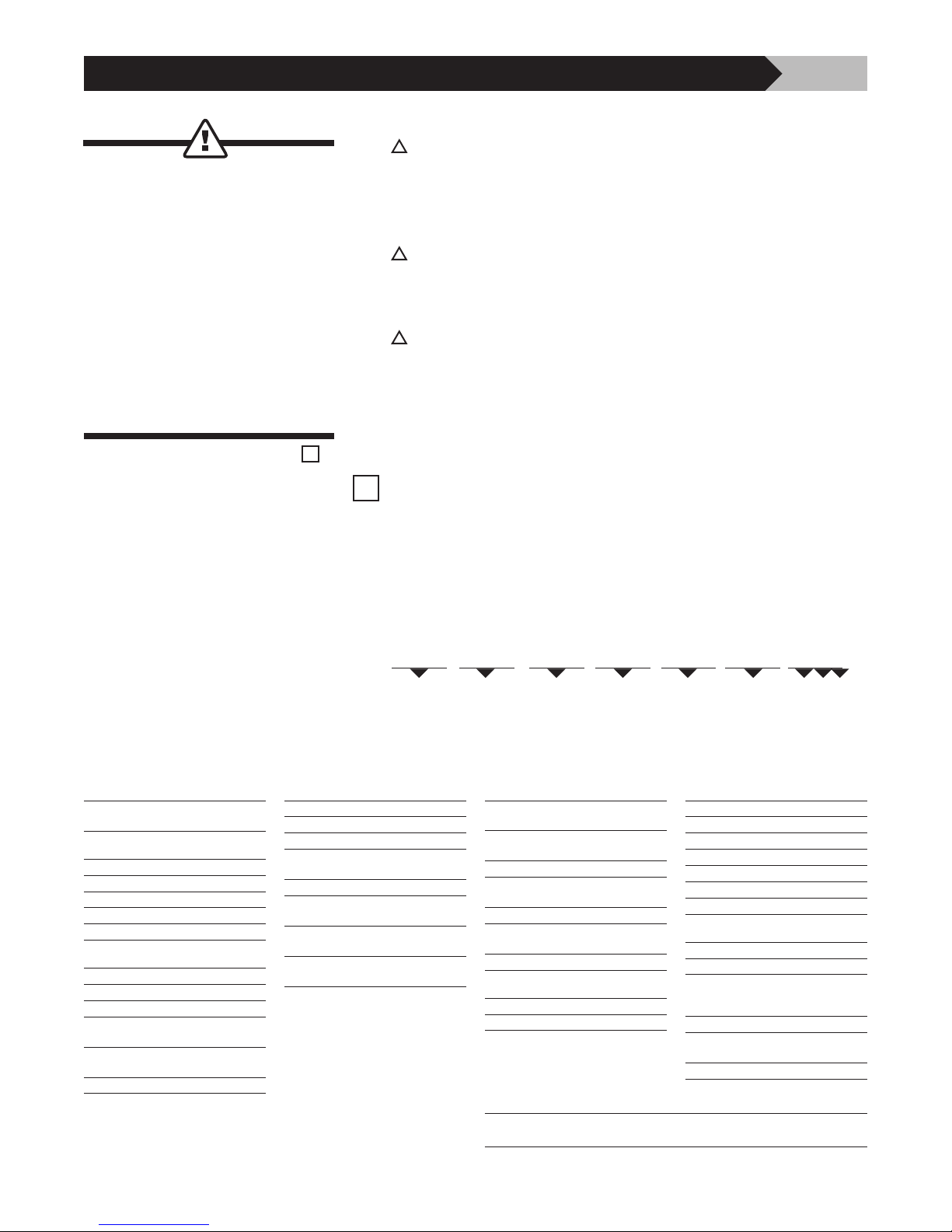
service configurations as per sample model number scheme in Table 1:
kA Rating
Available PX3TM kA Ratings:
050, 080, 100, 125*, 150*, 200*
Voltage**
208 120/208
240 120/240
380 220/380
480 277/480
600 347/600*
Configuration**
1G 1-Phase, Grounded
2G 2-Phase, Grounded, Split-Phase
3Y 3-Phase, Grounded, Wye
3R 3-Phase, Grounded,
High-Resistance
3H 3-Phase, Grounded,
High-Leg Delta
3D 3-Phase, Grounded, Delta
E.g.: PX3-050-208-3Y-MFT-M6E-F2D
PX3 — 050 — 208 — 3Y — MFT — M6E — F 2 D
Model
Enclosure
MFT Metal, Flush Mount, Top Feed
MFB Metal, Flush Mount, Bottom Feed
MST Metal, Surface Mount, Top Feed
MSB Metal, Surface Mount,
Bottom Feed
SFT Stainless, Flush Mount, Top Feed
SFB Stainless, Flush Mount,
Bottom Feed
SST Stainless, Surface Mount,
Top Feed
SSB Stainless, Surface Mount,
Bottom Feed
kA Rating
Monitoring
M0 No local monitoring (see remote
M1 LED/Phase + Audible Alarm, Dry
M2 M1 + Surge Counter
M3 Advanced Monitoring, Character
M4E M3 + Ethernet, Modbus TCP
M5 Advanced Monitoring, Graphics
M6E M5 + Ethernet, Modbus TCP
Filter
F Filter
N No Filter
Voltage
Configuration
MxX stand-alone option)
Relay Contacts
Display, Modbus RTU
Display, Modbus RTU
Enclosure
Optional Features
1 Panel Mounted In-House
2 Test Port
3 Type 2 SPD (UL 1283)
4 Full Flush Cover
5 GE Version
6 Square D Version
7 Siemens, Eaton Cutler-Hammer
Disconnect Option
D Integral Disconnect
Blank No Disconnect
Stand-Alone Options
(To Be Ordered As Separate Items)
DTS DTS-2 Diagnostic Test Set
MxX Remote Monitor Extension M1X
HPI HPI Cable
Monitoring
through M6EX
Filter Option
Optional Feature
Integral Disconnect
*Not available with Integral Disconnect.
** Consult factory for additional Voltage/Configuration options.
An area on the back cover of this manual is allocated to log your PX3
model number, purchase date, installation date, and installer
Table 1: Sample Model Number Scheme (PX3)
Page 5
CURRENT TECHNOLOGY® PX3TM INSTALLATION, OPERATION AND MAINTENANCE MANUAL
5
Pre-Installation Checklist
continued
✓
Check to ensure that a proper neutral-ground bond is installed between the
neutral and ground terminals at the transformer upstream from all 3-Phase
WYE, 3-Phase High-Leg DELTA, or 1-Phase SPLIT-PHASE PX3 devices (see
NEC article 250.) Lack of a proper bond will damage the PX3 and void the
warranty.
Confirm that the environmental conditions are consistent with the
following ranges:
• Ambient Temperatures: The PX3 must be installed in an area with a
temperature between -13° and +140°F (-25° and +60°C).
• Humidity: The PX3 must be installed in an area with relative humidity
between 5% and 95% non-condensing.
• Altitude: The PX3 must be installed in a location where the altitude is
below 13,000 feet.
W A R N I N G !
Discontinue installation if (1) your conditions are inconsistent with
the checklist above or (2) your conditions cannot be verified. Call
Thomas & Betts Power Solutions’ Technical Support at 800.238.5000
if you have any questions.
Installation Methods
(for the design engineer
and the installer)
This device features an internal protection that will disconnect the
surge protective component at the end of its useful life but will
maintain power to the load now unprotected. If this situation is
undesirable for the application, follow the manufacturer’s instructions
for replacing the device.
The PX3 is a Type 1 SPD which is suitable for use in both Type 1 and Type 2
SPD applications. The PX3 is a one-port SPD and is to be connected in parallel
with the electrical system. It may be connected via a circuit breaker, molded
case switch, fused switch, or connected directly to the bus of the panelboard
or switchboard it is protecting. If direct bus connection is used, Current
Technology, recommends that the PX3 be equipped with the optional integral
disconnect switch.
tnbpowersolutions.com/current_technology
Page 6
CURRENT TECHNOLOGY® PX3TM INSTALLATION, OPERATION AND MAINTENANCE MANUAL
NBA
C
PX3
PANELBOARD
N
G
NABC G
B
N
C
A
N
G
Xo BOND
EARTH
GROUND
C
B
A
N
G
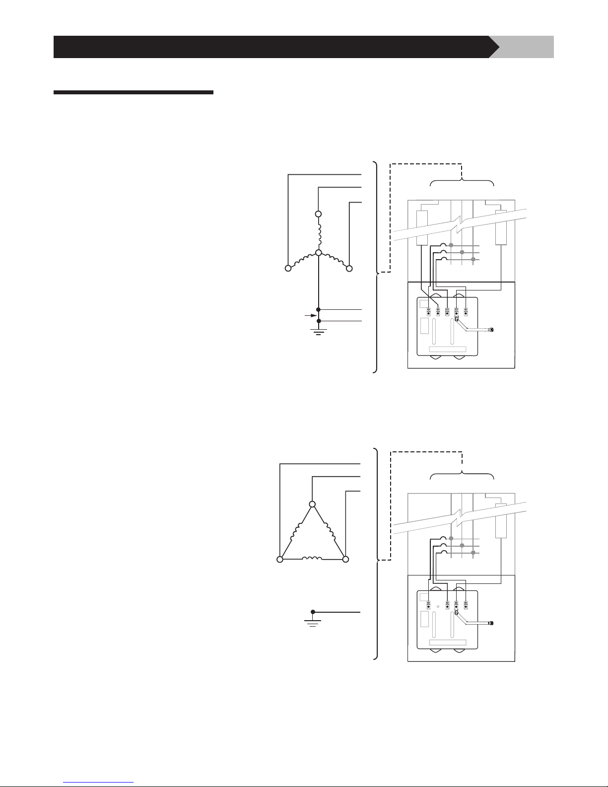
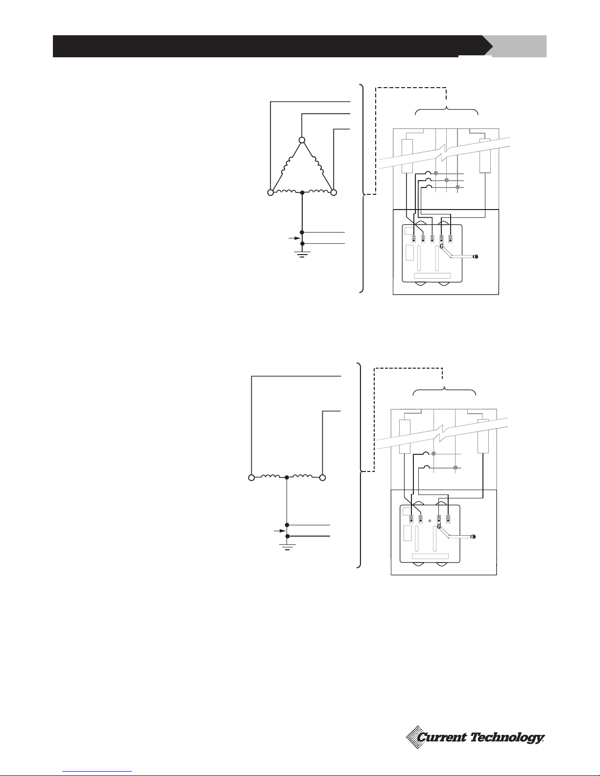
Figures 1-4 show the electrical relationship between the PX3 and these four
Service Configurations
basic service configurations: WYE, DELTA, High-Leg DELTA and SPLIT-PHASE.
6
Figure 1
3-Phase, 4-Wire Wye
Figure 2
3-Phase, 3-Wire Delta
C
B
A
B
C
Xo BOND
N
N
G
EARTH
GROUND
B
A
N
G
C
B
A
NABC G
N
NBA
ABCG
G
PANELBOARD
C
PX3
G
tnbpowersolutions.com/current_technology
C
G
EARTH
GROUND
A
B
G
A
C
PANELBOARD
PX3
Page 7
CURRENT TECHNOLOGY® PX3TM INSTALLATION, OPERATION AND MAINTENANCE MANUAL
NBA
C
PX3
PANELBOARD
N
G
NAB* CG
*NOTE: HIGH-LEG MUST BE B PHASE
N
G
Xo BOND
EARTH
GROUND
N
G
C
A
N
B*
C
B
A
7
Figure 3
3-Phase, 4-Wire High-Leg Delta
Figure 4
1-Phase, 3-Wire Split-Phase
C
Xo BOND
B*
N
N
G
EARTH
GROUND
C
B
A
A
N
G
*NOTE: HIGH-LEG MUST BE B PHASE
L2
NAB* CG
N
NBA
G
PANELBOARD
C
PX3
NL1L2G
L1
N
L2 L1
Xo BOND
N
G
EARTH
GROUND
N
N
G
C
NA
G
PANELBOARD
PX3
Page 8
CURRENT TECHNOLOGY® PX3TM INSTALLATION, OPERATION AND MAINTENANCE MANUAL
STAND ALONE MOUNTTOP FEED BOTTOM FEED
FLUSH MOUNT
PANELBOARD
PANELBOARD
PX3
PX3
PX3
ENCLOSURE
TRIM
TRIM
ENCLOSURE
TRIM
ENCLOSURE
3/4"
TYP.
PANELBOARD
8
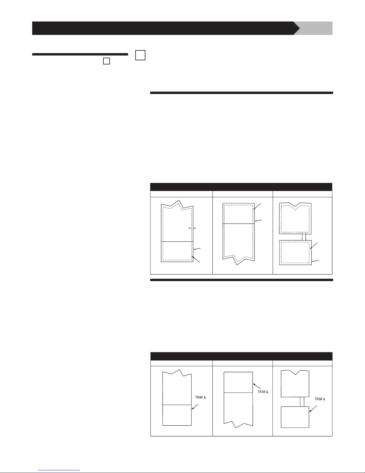
Plan Your Installation
✓
Before you begin assembly, check that the supplied trim kit is
appropriate for your particular installation. If you do not have the
correct trim hardware contact your supplier.
There are multiple installation options for the mechanical installation of the PX3.
Flush Mount Options
• Flush Mounted, Top Feed, Connected to the Panelboard – The PX3
trim plate is offset to fit underneath the panelboard’s trim plate when the
PX3 is mounted on the bottom of the panelboard.
• Flush Mounted, Bottom Feed, Connected to the Panelboard – The PX3
trim plate is offset to fit above the panelboards trim plate when the
PX3 is mounted on the top of the panelboard.
• Flush Mounted, Stand Alone – The PX3 trim plate does not mate with the
panelboard’s trim plate. (Choose "full flush cover" in options section)
PANELBOARD
3/4"
TYP.
FLUSH MOUNT
PX3
ENCLOSURE
TRIM
STAND ALONE MOUNTTOP FEED BOTTOM FEED
PANELBOARD
TRIM
PX3
ENCLOSURE
PANELBOARD
Surface Mount Options
• Surface Mounted, Top Feed, Connected to the Panelboard – The PX3
trim plate butts up next to the trim plate of the panelboard.
• Surface Mounted, Bottom Feed, Connected to the Panelboard – The PX3
trim plate butts up next to the trim plate of the panelboard.
• Surface Mounted, Stand Alone – The PX3 trim plate does not mate
with the panelboard’s trim plate.
SURFACE MOUNT
TOP FEED BOTTOM FEED STAND ALONE MOUNT
PANELBOARD
ENCLOSURE
PX3
ENCLOSURE
PANELBOARD
PANELBOARD
ENCLOSURE
PX3
TRIM
ENCLOSURE
tnbpowersolutions.com/current_technology
PX3
PX3
Page 9
CURRENT TECHNOLOGY® PX3TM INSTALLATION, OPERATION AND MAINTENANCE MANUAL
Open the cover of the PX3 and carefully disconnect all cables from the circuit
Remove the Cover
boards mounted on the door.
Remove the door from the enclosure by removing the screws. Set the door
aside.
®
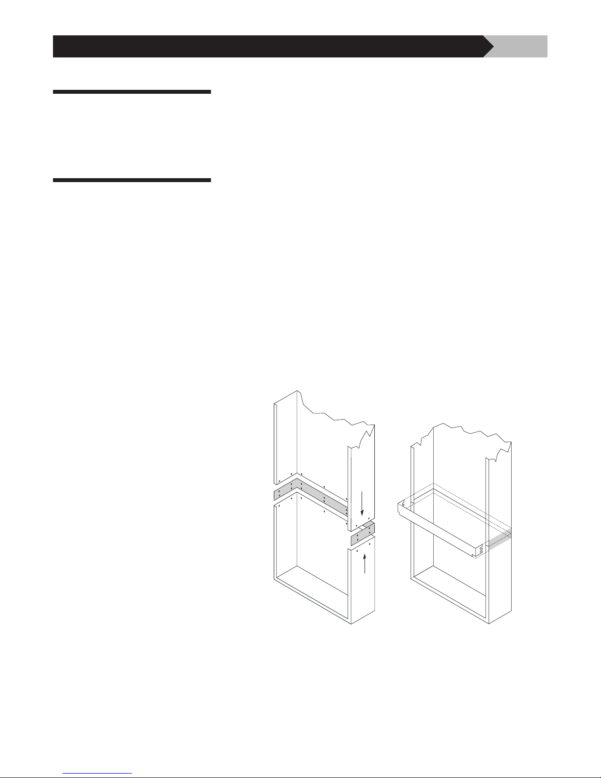
recommends attaching the PX3 enclosure to the top or
Attaching the PX3
to the Panelboard
Current Technology
bottom of the panelboard’s enclosure so that the two enclosures are joined
without a barrier. It is best to do this before the panelboard is mounted to the
structure.
To join the two enclosures, the top or bottom endplate of the PX3 may
be removed. Similarly, the top or bottom endplate of most commercial
panelboards may be removed.
9
If your panelboard is TOP-FEED, remove the bottom endplate of the
panelboard and the top endplate of the PX3.
™
If your panelboard is BOTTOM-FEED, remove the top endplate of the
panelboard and the bottom endplate of the PX3.
™
Attach the PX3 to the panelboard using the supplied collar hardware and
screws. Refer to the illustration above showing an PX3 being mounted to the
bottom of a panelboard.
Tip: Use of small C-clamps helps hold the parts in place while the screws
are inserted and tightened.
Note: The panelboard and PX3 enclosures can also be joined together using a
close nipple, lockwashers and bushings. Such installations, however, may limit
the ability to pass conductors between the two enclosures.
Page 10
CURRENT TECHNOLOGY® PX3TM INSTALLATION, OPERATION AND MAINTENANCE MANUAL
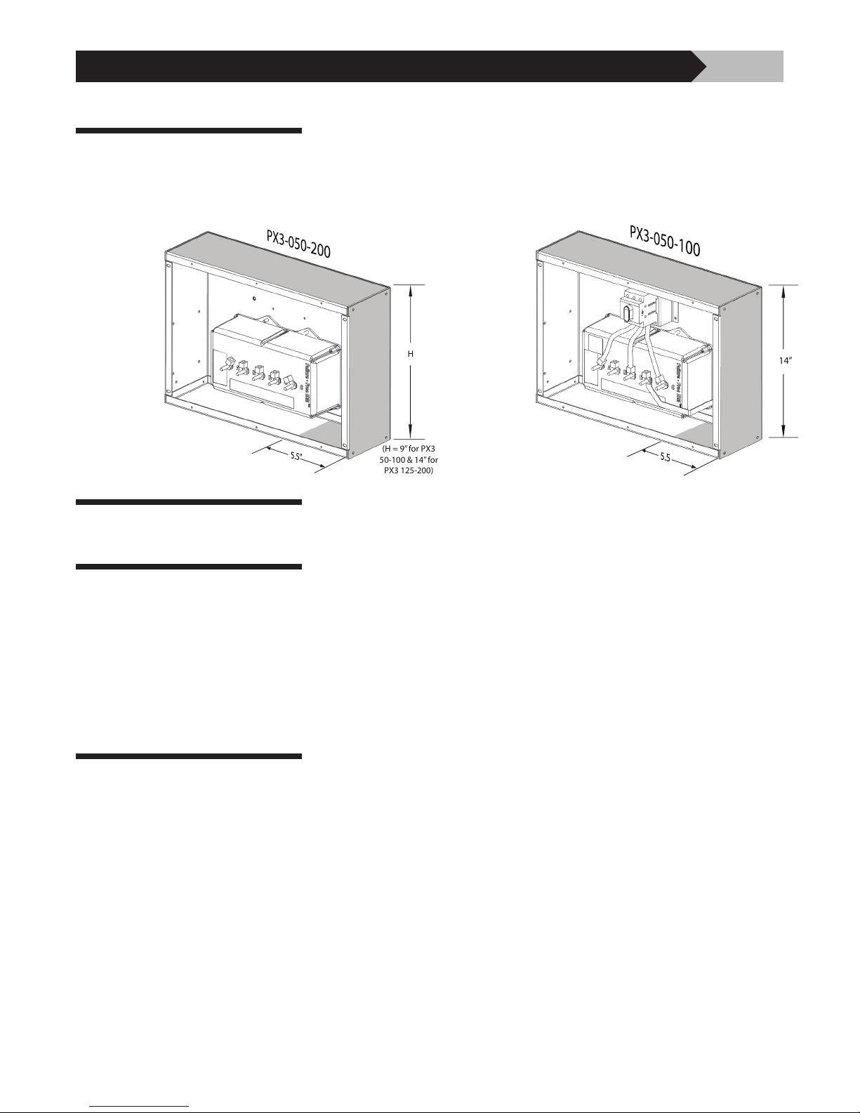
14”
H
(H = 9” for PX3
50-100 & 14” for
PX3 125-200)
Conduit Openings
■ ALLOWABLE AREA FOR CONDUIT ENTRY
10
Figure 5
Standard
PX3 Without
Disconnect
Punch Conduit Openings
Mount the Panelboard
and PX3 Assembly
Figure 6
PX3 With
Disconnect
If desired, punch holes for branch circuit conduits at this time or wait until the
PX3 and panelboard are mounted to the structure.
Mount the joined panelboard and PX3 to the building structure using
construction methods and hardware appropriate for your site. Be sure to
fasten both the PX3 enclosure and the panelboard enclosure to the building
structure.
Electrical Connections
tnbpowersolutions.com/current_technology
If you choose to mount the PX3 as a stand-alone enclosure, locate the
PX3 enclosure according to the guidelines in the following section
“Electrical Connections”.
Phases, Neutral* and Ground: Connect the phase, neutral and ground
conductors. Connect the phase conductors to the lugs labeled “A,” “B,” and
“C” on the ISM and the ground and neutral* conductors to the lugs labeled
“G” and “N.” The terminal lugs of the ISM in the PX3 must be electrically
connected by the installer to the appropriate terminals in the panelboard.
Before making connections, read and remove the WARNING tag from the
ground lug marked “G” on the ISM.
Overcurrent Protection: Connect the phase conductors to circuit breakers in
®
the panelboard. Current Technology
recommends using circuit breakers in the
range of 60 to 100 amps.
Note: If applicable, please consult specifying engineer’s recommendation prior
to making connections.
* Delta-configured PX3 models do not have a Neutral Lug.
Page 11
CURRENT TECHNOLOGY® PX3TM INSTALLATION, OPERATION AND MAINTENANCE MANUAL
5.50”
11
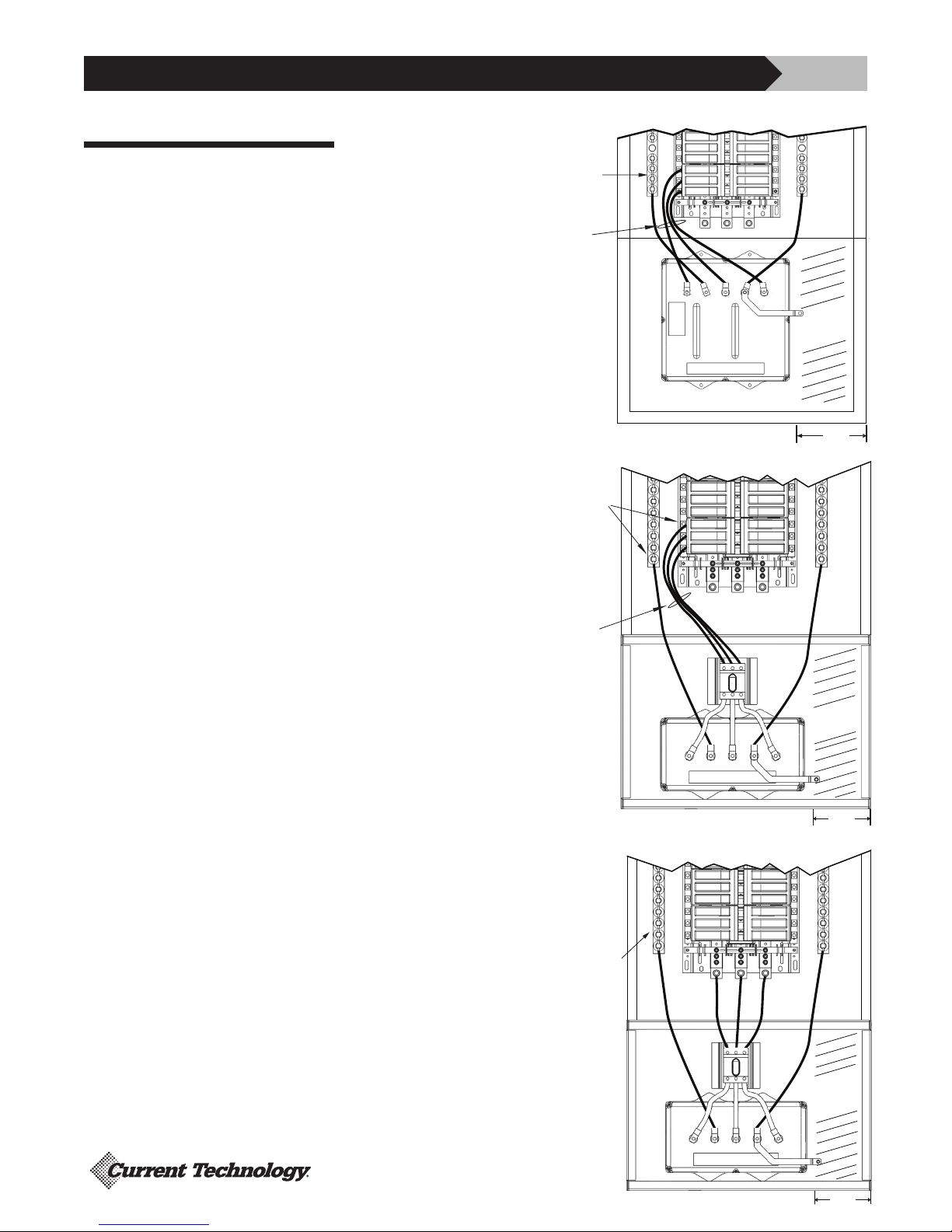
Conductor Routing
The following factors should be
addressed during the design of an
installation to ensure that there is a
suitable place for the PX3 reserved
next to its point of connection to
the electrical system. The selected
mounting location should ensure short
conductor runs providing a direct route
with a minimum of bends. If bends
are required they should be sweeping
bends. Do not make sharp 90˚ bends for
aesthetic purposes.
These illustration show suggested
conductor routing for a top-feed
panelboard. Routing in bottom-feed
panelboards is similar but reversed.
Note that conductors from the PX3
always connect within the panelboards
to lugs or breakers closest to the PX3.
The lugs on the PX3 ISM may be rotated
to facilitate routing.
Figure 7
Standard
PX3 Without
Disconnect
Figure 8
PX3 Using
Breakers
Connected With
Disconnect
USE BREAKERS,
NEUTRAL &
GROUND
NEAREST PX3
UNIT
ROUTING
FROM BREAKERS
USE BREAKERS,
NEUTRAL &
GROUND
NEAREST PX3
UNIT
ROUTING
FROM BREAKERS
N
B
N
A
N
G
C
G
WIREWAY
ALLOWANCE
5.50”
G
WIREWAY
ALLOWANCE
Figure 9
PX3 Direct Bus
Connected With
Disconnect
Also refer to Figures
1 through 4 for
a schematic of
connections for different
service configurations.
USE NEUTRAL
& GROUND
NEAREST PX3
UNIT
G
A
N
N
N
A
C
B
G
WIREWAY
ALLOWANCE
G
C
B
5.50”
Page 12

CURRENT TECHNOLOGY® PX3TM INSTALLATION, OPERATION AND MAINTENANCE MANUAL
If the PX3 is mounted detached, the performance of the PX3 will be severely
limited if the conductors are too long, are of too small a wire gauge, have too
many bends, or have sharp bends.
Conductor Length and Sizing: Conductor length must be kept as short
Conductor Sizing and
Overcurrent Protection
as possible and avoid sharp bends. Conductor length must never exceed 10
feet in length from phase bus through the PX3 to the neutral bus or ground
bus. If the lead length must exceed 10 feet, Current Technology
using our HPI low impedance cable for installing the product. The following
conductor sizes for phase, ground and neutral connections are recommended.
Table 2: Maximum Recommended Conductor Size
Use conductor lengths less than 10 feet
Model Without Disconnect With Disconnect
PX3-050 #6 AWG #6 AWG
PX3-080 #6 AWG #6 AWG
PX3-100 #6 AWG #6 AWG
PX3-125 #2 AWG Product Not Available
PX3-150 #2 AWG Product Not Available
PX3-200 #2 AWG Product Not Available
12
®
recommends
NOTE: Table 2 conductor sizing recommendations ensure that the effective
clamping voltage of the PX3 at the point of connection is kept to a minimum in
order to maximize protection.
Overcurrent Protection: As a Type 1 SPD the PX3 does not require
upstream overcurrent protection for safe operation, however, the design may
require or the installer may choose to connect the PX3 to a circuit breaker,
molded case switch or fused disconnect.
tnbpowersolutions.com/current_technology
Page 13
CURRENT TECHNOLOGY® PX3TM INSTALLATION, OPERATION AND MAINTENANCE MANUAL
NEMA 1 enclosures are suitable for indoor use only.
Indoor Installations
Current Technology® recommends feeding all PX3 models with a disconnect,
circuit breaker, molded case switch or fused disconnect.
13
Neutral to Ground Filter
Jumper
If a breaker or molded case switch is used for connecting the phase
®
conductors, Current Technology
recommends using circuit breakers
in the range of 60 to 100 amps.
W A R N I N G ! Prior to proceeding, ensure the SPD unit does not
have voltage applied to its input terminals.
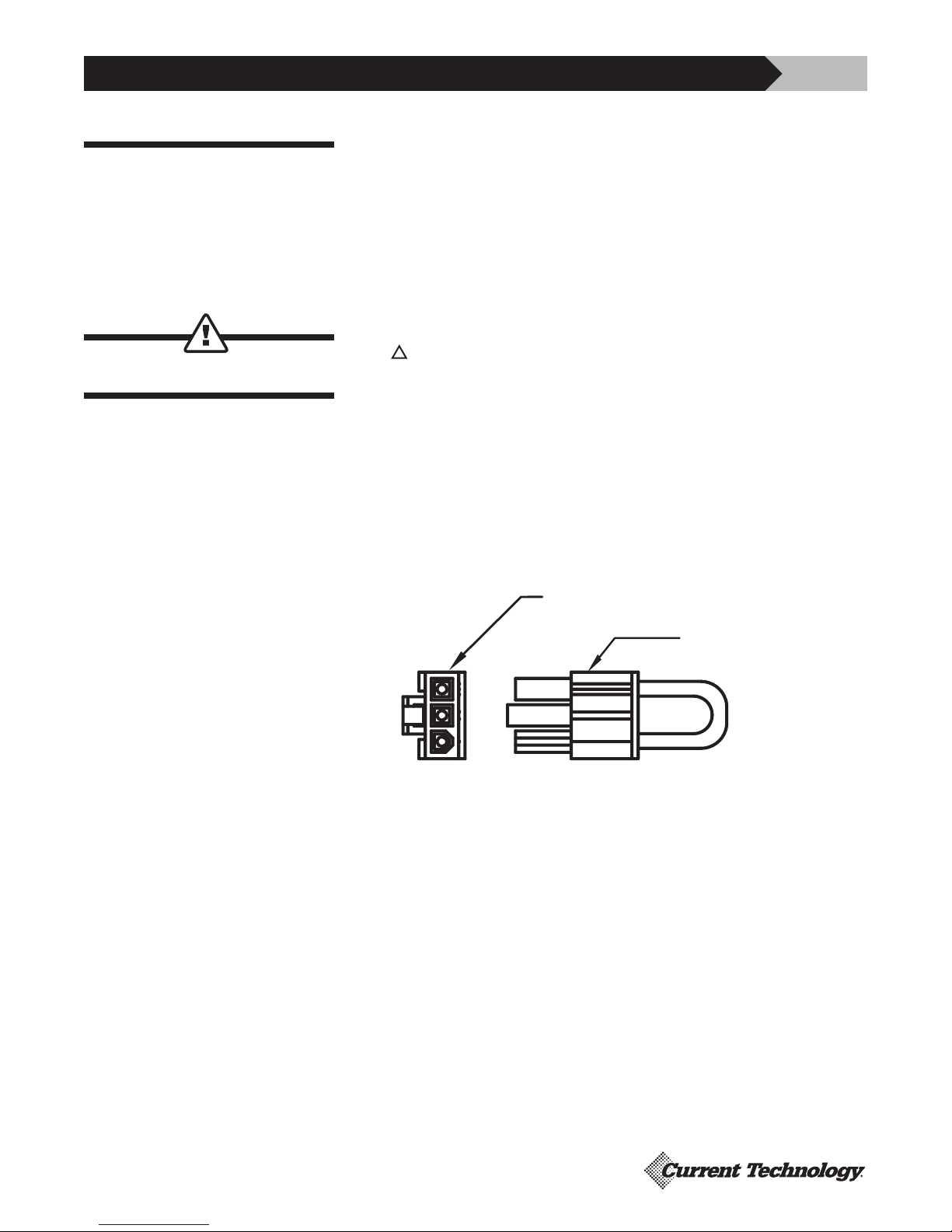
PX3 models equipped with a filter system (“-F” suffix), and have a neutral
connection, come with a green jumper wire that loops out of the 3-pin
connector on the ISM and connects a filter neutral to ground. In certain
medical applications, or circuits which employ GFCI protection, this Neutral to
Ground filter connection should be removed.
Connector on ISM
TM
Neutral to Ground Jumper
Removed from ISM
TM
Figure 10
Removal is accomplished by pulling the green jumper from the connector on
the ISM. Once removed, the jumper should be placed in the clear vinyl pocket
containing the unit test data for future use if desired (Figure 10).
Page 14
CURRENT TECHNOLOGY® PX3TM INSTALLATION, OPERATION AND MAINTENANCE MANUAL
14
Before Applying Power
Checklist
✓
Field Testing: Your PX3 has been carefully tested before leaving the factory.
However, the performance of this unit as a surge suppression device can be
confirmed in the field prior to startup using a portable DTS-2 Tester.
The optional DTS-2 Tester may have been purchased along with your PX3 or
Field Startup Testing Service may have been specified during the purchase of
™
the PX3.
Check with the owner or owner’s representative to see if this test is
required at your site.
If you have questions about Field Startup Testing or would like to
®
arrange for this service, call Current Technology
Technical Support at
800.238.5000.
Confirm Pre-Installation Checklist: Confirm that the “Pre-Installation
Checklist” found in the beginning of this manual was completed correctly
before proceeding.
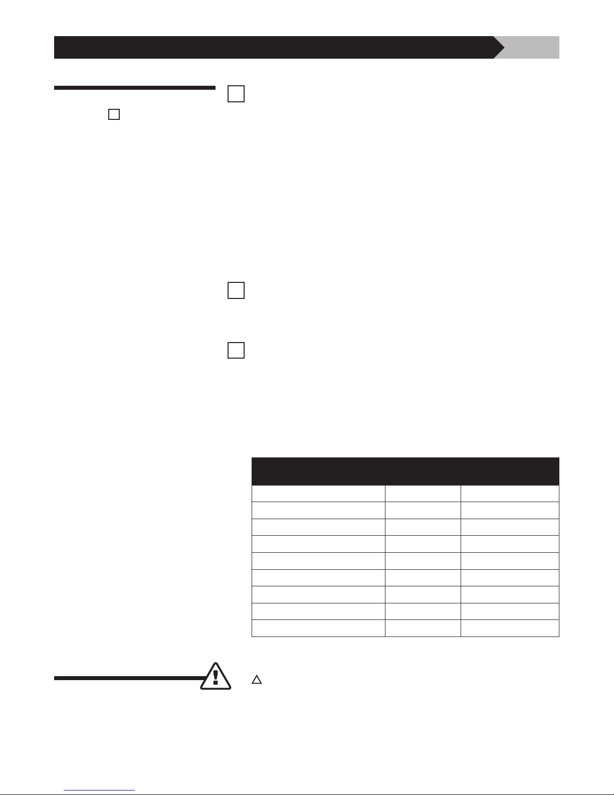
Confirm Line Voltage: Measure the line to line voltages feeding the
panelboard or disconnect and be sure they are within ±10% of the rated
line voltage of the PX3. Use the following table to determine the range of
acceptable voltages for each model of the PX3. The power system operating
frequency should be between 47–63 Hz.
W A R N I N G !
Table 3: Acceptable Voltage Ranges for All PX3 Models
PX3
MODEL NO.
NOMINAL
L-L VOLTAGE
-10% TO +10%
L-L VOLTAGE
PX3-xxx-240-2G-xxx-xx-xx 240 216 to 264
PX3-xxx-208-3Y-xxx-xx-xx 208 188 to 228
PX3-xxx-380-3Y-xxx-xx-xx 380 342 to 419
PX3-xxx-480-3Y-xxx-xx-xx 480 432 to 528
PX3-xxx-600-3Y-xxx-xx-xx 600* 540 to 660
PX3-xxx-240-3H-xxx-xx-xx 240 216 to 264
PX3-xxx-240-3D-xxx-xx-xx 240 216 to 264
PX3-xxx-480-3D-xxx-xx-xx 480 432 to 528
PX3-xxx-600-3D-xxx-xx-xx 600* 540 to 660
*Not available with Integral Disconnect
Note: first “xxx” specifies rating of 050, 080, 100, 125, 150, 200kA
W A R N I N G !
Do not apply power if the measured voltage is not within the range
specified for the PX3 model being installed.
➤ Apply power to the PX3 by closing the circuit breaker or switch (if any)
feeding the PX3 or closing the PX3 integral disconnect.
Page 15
CURRENT TECHNOLOGY® PX3TM INSTALLATION, OPERATION AND MAINTENANCE MANUAL
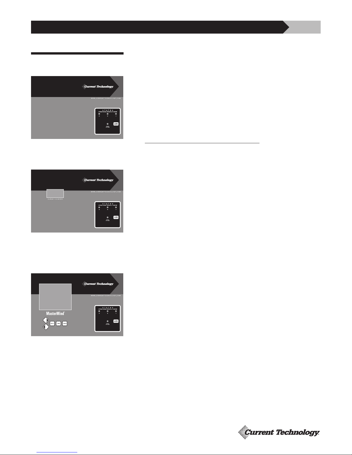
➤ If your PX3 has M1 Standard Monitoring (see Figure 11):
Verify Proper Operation
Verify that only the green indicating lights are illuminated and that there are no
red lights illuminated. Green lights indicate a normal condition for each phase.
Orange lights indicate protection of 40–75% and Red lights indicate protection
of <40%. Three-phase units have three (3) green indicating lights labeled “A”,
“B”, and “C”. Split-phase units should only have lights “A” and “C” illuminated.
See table below for LED status indication.
The M1 Standard Monitoring is equipped with a dual set of Form “C” contacts
(see Figure 12). The relay containing the contacts is in the “alarm condition”
or normally closed when the power is off to the unit, when the unit is
Figure 11: PX3 with M1 Standard
Monitoring.
encountering loss of power to one or more phases, or the PX3 is encountering
more than 40% loss of capacity due to internal fuse operation. Test the
operation of the Form “C” contacts by de-energizing the PX3 and checking
the state of the contacts with a continuity tester or observing the effect of the
contacts on the user provided remote alarm circuits.
15
Figure 12: PX3 with M2 Standard
Monitoring with Surge Counter.
Figure 13: PX3 with MasterMind
Advanced Monitoring
➤ If your PX3 has the M2 Option (See Figure 12):
The M2 option is equipped with a surge counter. The number of surges
detected by the counter is displayed on a 6-digit LCD display on the front
of the PX3 door. The surge counter will also increment each time power is
applied to the unit after being in the “off” state. The counter can be reset by
pressing the button on the front of the counter.
The M1 and M2 Standard Monitoring also contain an audible alarm that
should not operate under normal conditions. To silence audible alarm,
press ALARM SILENCE button on display.
®
➤ If your PX3 is equipped with the MasterMind
Advanced Monitoring
Option (see Figure 13)
®
Please refer to the MasterMind
®
manual for Specifications and Operation.
tnbpowersolutions.com/current_technology
Page 16
CURRENT TECHNOLOGY® PX3TM INSTALLATION, OPERATION AND MAINTENANCE MANUAL
DRC1 DRC2
Table 4: LED and Display Alarm Status Conditions
16
Condition Corresponding Phase LED
Alarm
Cond
M3 Status Message** Priority *
Phase Loss (<80%) LED Off Y Alarm: Phase x Loss 1A
Phase Low (80 to <90%) LED Short Blink Green (≈25% duty) Y Alarm: Phase x Low 1B
Phase High (>110%) LED Long Blink Green (≈75% duty) Y Alarm: Phase x High 1C
N-G OverVoltage N/A Y Alarm: N-G Voltage High 2
Frequency Out of Range N/A Y Alarm: Frequency
3
Out of Range
% Protection < XX% LED On Red Y Alarm: Protection x Low 4
Filter/Cap Loss LED Blink Red once every 2 seconds Y Alarm: Protection Filter x Loss 5
% Protection XX to YY% LED On Orange N Alarm: Protection x Reduced 6
Notes:
* 1 Highest priority takes precedence: I.e. if phase is lost, LED is Off, no blinking even if filter loss. Alarm Condition means the Audible Alarm is ON, Dry Relay Contacts is OFF
(de-energized), and System Alarm LED is ON.
2 % Protection levels of 40% and 75% are default settings which can be changed by the user (M3 System only). If the Surge Module or Current Rating settings are changed,
the Protection levels will change automatically.
** 3 Subsequent Status message will be displayed on M3 Character and Graphics Displays, where “x” is corresponding Phase (A, B, C or L1, L2). The Highest Priority condition
will over-write earlier conditions. Messages may be truncated to fit screen area (with T&B acceptance).
4 Red System Status LED will remain on after Status has returned to normal. User must clear the status by pressing the M3 Cancel button.
5 Alarm Conditions will also be logged in the Events Log.
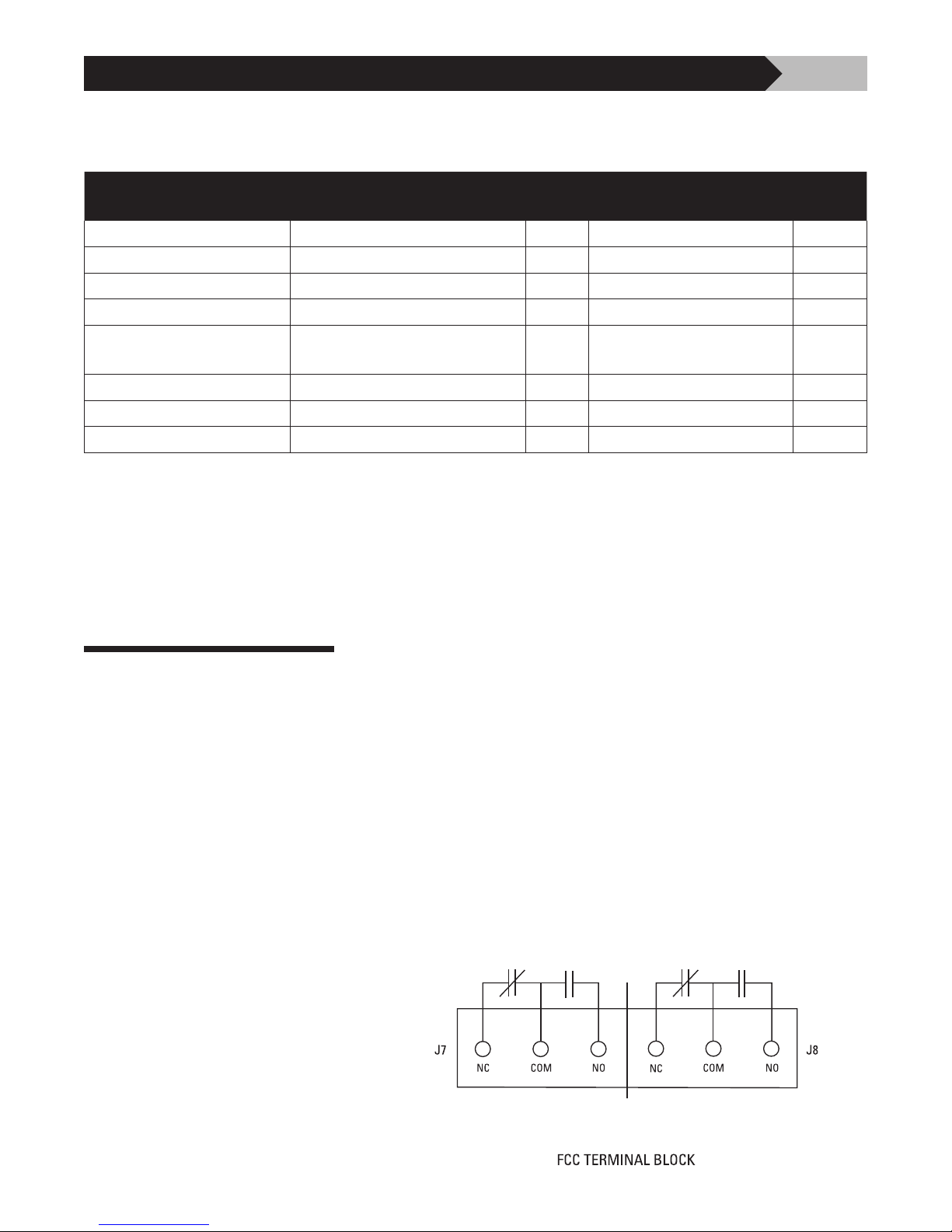
Connecting Form “C”
Dry Contacts
Dry Contacts: All PX3 models have a dual set of Form “C” dry contacts
available for connection to user-provided remote alarm and monitoring circuits.
The installer must provide the appropriate raceway and wiring for this circuit
observing the restrictions on conduit openings illustrated in an earlier section
of this manual. The installer must route the monitoring conductors to the blue
terminal blocks on the door-mounted circuit board. Choose the appropriate
materials and routing to allow the door to open and close without pinching or
stressing wires.
Figure 14 shows the Form “C” contact configuration. The annotations on the
diagram match the markings on the blue terminal block.
DRC1 DRC2
tnbpowersolutions.com/current_technology
Figure 14
• Rated 250V 2A DC, 250V 5A AC, 14-22 AWG
Page 17

CURRENT TECHNOLOGY® PX3TM INSTALLATION, OPERATION AND MAINTENANCE MANUAL
Your Current Technology® PX3 surge suppression system does not require
Troubleshooting
periodic maintenance. The unit contains no serviceable parts. The unit’s
heavy-duty design should preclude the need for any repairs; however, the
following indications and procedures can be checked (See Table 5):
Table 5: Troubleshooting Checklist
INDICATION PROCEDURE
17
One or more phase
indicator lights are off
• Check that the external power source
supplying power to unit is energized
• Check that the circuit breaker or switch (if
appropriate) feeding the PX3 is turned “on”
Phase status lights
are orange, indicating
40–75% protection
• Check the cables connecting the doormounted devices to the suppression module.
Exercise caution as High Voltage is present
on door mounted PCBs
Phase status lights
are red, indicating
<40% protection
• If all of above are O.K., contact factory
• If breaker is tripped, use a portable Diagnostic Test Set (DTS-2) to verify unit
integrity before resetting the breaker
Portable Diagnostic Test
Set (Current Technology
®
Contact factory
Model DTS-2) indications
are not in range* for the
product
Installation Assistance
*Ranges are located on the underside of DTS-2 lid.
Our staff is available to support you.
Monday through Friday, 8:00 a.m. to 5:00 p.m. (EST):
800.238.5000 or 804.236.3300
Page 18

CURRENT TECHNOLOGY® PX3TM INSTALLATION, OPERATION AND MAINTENANCE MANUAL
When properly installed the PX3 Surge Suppression System will provide years
Operation/Maintenance
of uninterrupted service.
With several levels of monitoring available, the user should be able to verify the
normal operation of the PX3 and confirm that it is connected correctly to the
power system.
®
Current Technology
does recommend testing in order to verify that the unit is
able to clamp surges to an acceptable level.
This test should be coordinated with scheduled maintenance events in your
facility. It can be performed in-house with the aid of the DTS-2 Portable Test
Set or requested as a service from a Current Technology
representative.
The PX3 Surge Suppression System is available with the following options:
Options
18
®
authorized service
Stand-Alone Options
Standards and Listings
M1 LED/Phase + Audible Alarm, Dry Relay Contacts
M2 M1 + Surge Counter
M3 Advanced Monitoring, Character Display, Modbus RTU
M4E M3 + Ethernet, Modbus TCP
M5 Advanced Monitoring, Graphics Display, Modbus RTU
M6E M5 + Ethernet, Modbus TCP
DTS DTS-2 Diagnostic Test Set
MxX Remote Monitor Extension M1X through M6EX
HPI HPI Cable
The following standards and listings apply to the PX3 product line:
• UL Listed 1449 4th Edition for Type 1 and Type 2 SPD applications, cUL,
and UL 1283
• Meets Requirements for UL 96A
• Compliant to IEEE C62.41.1-2002, C62.41.2-2002 and C62.45-2002
• NFPA 70 [NEC], Article 285
tnbpowersolutions.com/current_technology
• RoHS Compliant
Page 19
CURRENT TECHNOLOGY® PX3TM INSTALLATION, OPERATION AND MAINTENANCE MANUAL
Appendix
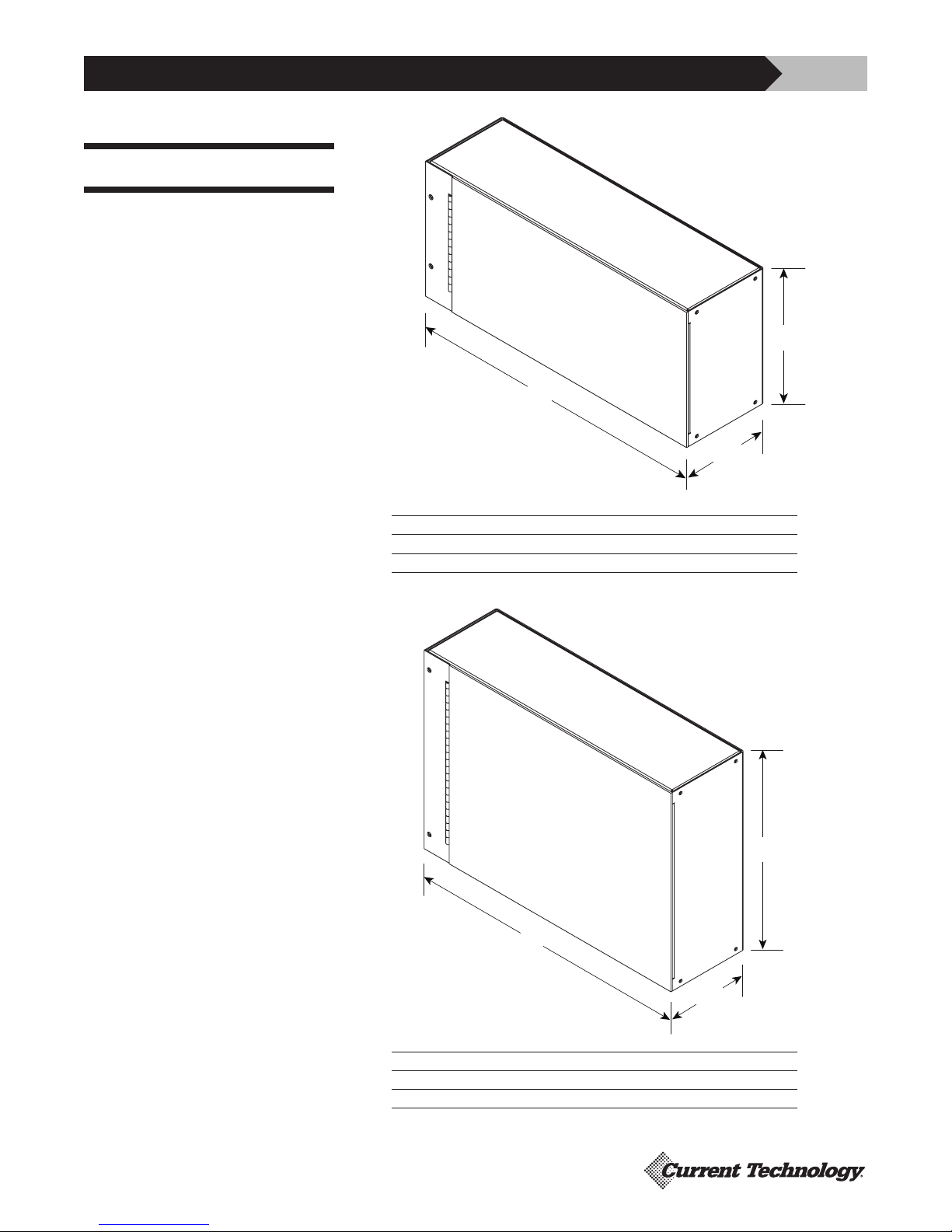
Dimensional Specifications
Figure 15
TM
050 – 100
PX3
PX3TM Inches (mm)
H 9.00 (228.6)
W 20.00 (508.0)
D 5.75 (146.0)
19
(H)
(W)
(D)
Figure 16
TM
PX3
125 – 200 and
TM
050 – 100 with Integral
PX3
Disconnect
(H)
(W)
(D)
PX3TM Inches (mm)
H 14.00 (355.6)
W 20.00 (508.0)
D 5.75 (146.0)
Page 20

CURRENT TECHNOLOGY® PX3TM INSTALLATION, OPERATION AND MAINTENANCE MANUAL
Thomas & Betts Power Solutions, LLC / Current Technology® warrants that
15 Year Limited Warranty
PX3 suppression filter systems (the “Product”), shall meet applicable industry
standards and specifications and be free from defects in materials and/or
workmanship. Should any failure of the Product to conform to this warranty
appear within fifteen (15) years from the date of the purchase of the Product,
Thomas & Betts Power Solutions shall either repair or replace the defective
Product, or part thereof, upon return to Thomas & Betts Power Solutions’
manufacturing facility in Richmond, Virginia with transportation charges prepaid.
Thomas & Betts Power Solutions shall have no liability under this warranty for
any problems or defects directly or indirectly caused by misuse of the Product,
alteration of the Product (including removal of any warning labels), accident,
neglect or improper installation, application, operation, or repair of the Product.
20
Model #
Date of Purchase
THE WARRANTY STATED HEREIN IS THE SOLE AND EXCLUSIVE WARRANTY
FOR CURRENT TECHNOLOGY
®
PRODUCTS, AND IS IN LIEU OF ALL OTHER
EXPRESS AND IMPLIED WARRANTIES. THOMAS & BETTS POWER SOLUTIONS
SPECIFICALLY DISCLAIMS ALL OTHER EXPRESS AND IMPLIED WARRANTIES,
INCLUDING, BUT NOT LIMITED TO, ALL IMPLIED WARRANTIES OF
MERCHANTABILITY AND FITNESS FOR A PARTICULAR PURPOSE. Installation,
operation, or use of the Product for which this warranty is issued shall
constitute acceptance of the terms hereof.
The liability of Thomas & Betts Power Solutions under this warranty is
expressly limited to the replacement or repair of the defective Product or the
defective part thereof, at Thomas & Betts Power Solutions’ sole option.
IN NO EVENT SHALL THOMAS & BETTS POWER SOLUTIONS BE LIABLE FOR
SPECIAL, INCIDENTAL, OR CONSEQUENTIAL DAMAGES OF ANY KIND OR
CHARACTER. IN NO EVENT WILL THOMAS & BETTS POWER SOLUTIONS’
LIABILITY EVER EXCEED THE PURCHASE PRICE PAID FOR SUCH DEFECTIVE
PRODUCT.
This warranty is not transferable and may only be enforced by the purchaser.
Claims under this warranty must be submitted to Current Technology
®
within
thirty (30) days of discovery of any PX3 product defect.
Warranty Period
PX3™ 15 Years from original date of purchase
Date Installed
Installer
© 2018, Thomas & Betts Power Solutions, LLC. • Thomas & Betts Power Solutions, LLC., is a wholly owned subsidiary of Thomas & Betts Corporation.
Current Technology
®
is a registered trademark of Thomas & Betts Corporation • Specifications are subject to change without notice. • Visit our website for latest revisions.
Thomas & Betts Power Solutions
5900 Eastport Blvd. • Richmond, VA 23231-4453 USA
Tel: (804) 236-3300 • Toll free: (800) 238-5000 • Fax: (804) 236-4841
tnbpowersolutions.com/current_technology
PN 750-0062-003 B00 081418
 Loading...