

Page 1
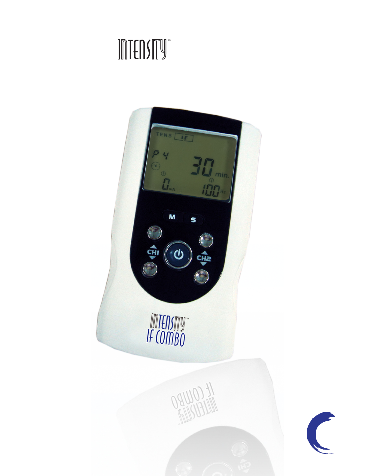
if combo
INSTRUCTION MANUAL
Page 2

This manual is valid for the InTENSity
TM
IF
Combo TENS and IF Stimulator
This user manual is published by Current Solutions™, LLC
Current Solutions™, LLC does not guarantee its contents and
reserves the right to improve and amend it at any time without prior
notice. Amendments may however be published in new editions of
this manual.
All Rights Reserved. Rev. V1.1 © 2010
: United States Federal Law restricts this device to sale by or
on the order of a physician or licensed practitioner
Conformity to safety standards
Current Solutions™, LLC declares that the device complies
with following normative document:
IEC60601-1, IEC60601-1-2, IEC60601-2-10, IEC60601-1-4,
ISO10993-5, ISO10993-10, ISO10993-1
Page 3
Table of Contents
1.SAFETY INFORMATIO
1.1 General description
1.2 Medical background
1.3 Indication for use
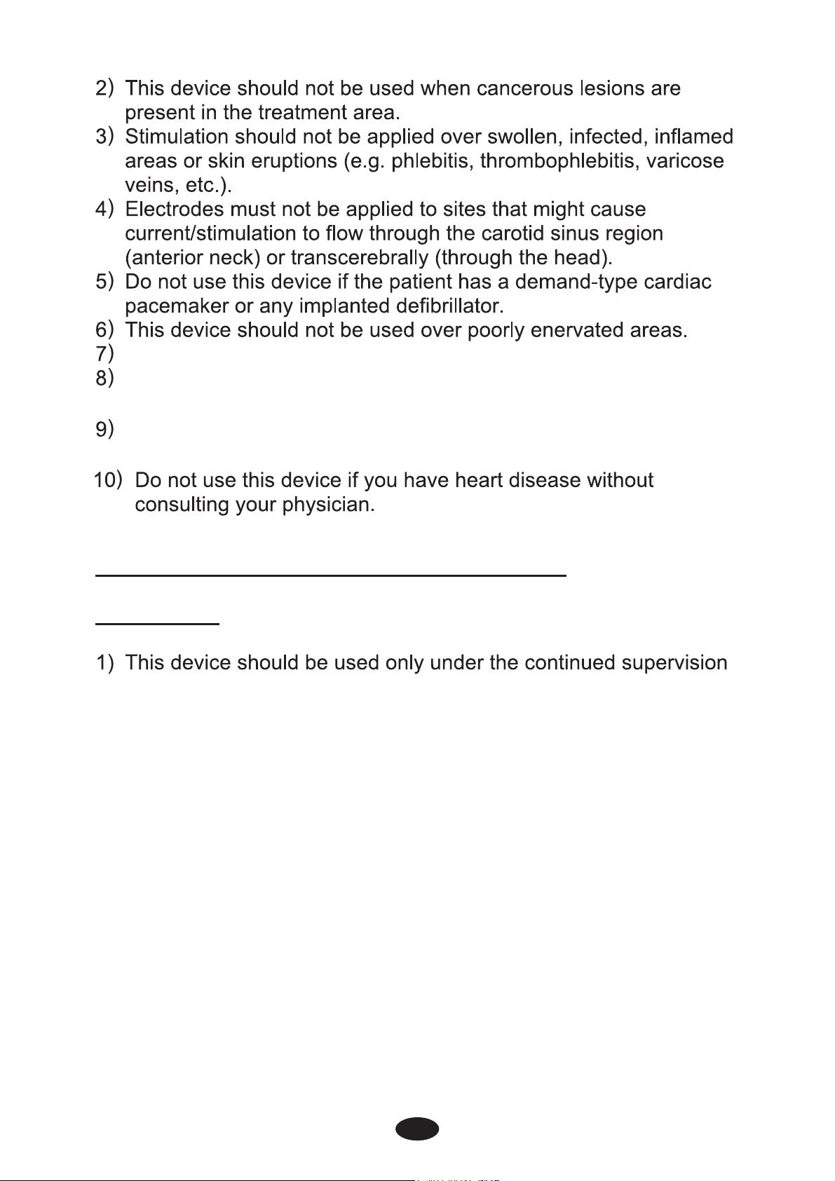
1.4 Contraindications
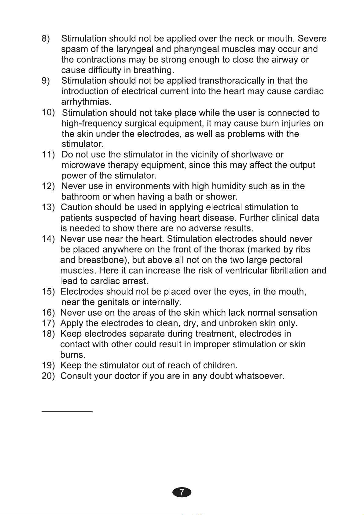
1.5 Warnings, Cautions, Adverse Reactions
2.PRESENTATION………
2.1 Front and Rear panel
2.2 LCD display
3.SPECIFICATION
3.1 Accessories
3.2 Technical information
3.3 The waveforms of the stimulation programs
4.INSTRUCTION FOR U
4.1 Battery
4.2 Connect electrodes to lead wires
4.3 Connect lead wires to device
4.4 Electrodes
4.5 Turn ON
4.6 Select the Therapeutic Mode
4.7 Steps to set a new program
4.8 Adjust Channel Intensity
4.9 Safety Lock Feature
4.10 Stop the treatment
4.11 Turn OFF
4.12 Low battery indicator
4
5.PROGRAM……………………………………………………….……23
6.
6.1 Tips for skin care
6.2 Cleaning the device
6.3 Electrodes
6.4 Cleaning the Electrode cords
6.5 Maintenance
7.TROUBLESHOOTIN
8.STORAGE…………………………
9.
10.ELECTROMAGNETIC COMPATIB
11.GLOSSARY OF SYMBLOS
…………………………………….……...24
Page 4

1. Safety information
4
1.1 General
InTENSity
featuring two therapeutic modes: Transcutaneous Electrical Nerve
Stimulation (TENS) and Interferential (IF), which are used for pain
relief. The stimulator sends gentle electrical current to underlying
nerves and muscle group via electrodes applied on the skin. The
parameters of device are controlled by the buttons on the front panel.
TM
IF Combo stimulator is a portable electrotherapy device
The
intensity level is adjustable according to the needs of patients.
1.2 Medical background
EXPLANATION OF PAIN
Pain is a warning system and the body’s method of telling us that
something is wrong. Pain is important; without it abnormal conditions
may go undetected, causing damage or injury to vital parts of our
bodies. Even though pain is a necessary warning signal of trauma or
malfunction in the body, nature may have gone too far in its design.
Aside from its value in diagnosis, long-lasting persistent pain serves
no useful purpose. Pain does not begin until coded message travels
to the brain where it is decoded, analyzed, and then reacted to. The
pain message travels from the injured area along the small nerves
leading to the spinal cord. Here the message is switched to different
nerves that travel up the spinal cord to the brain. The pain message
is then interpreted, referred back and the pain is felt.
EXPLANATION OF TENS
Transcutaneous Electrical Nerve Stimulation (TENS) is a noninvasive, drug free method of controlling pain. TENS uses tiny
electrical impulses sent through the skin to nerves to modify your
pain perception. TENS does not cure any physiological problem; it
only helps control the pain. TENS does not work for everyone;
however, in most patients it is effective in reducing or eliminating the
pain, allowing for a return to normal activity.
HOW TENS WORKS
There is nothing “magic” about Transcutaneous Electrical Nerve
Stimulation (TENS). TENS is intended to be used to relieve pain.
The TENS unit sends comfortable impulses through the skin that
stimulate the nerve (or nerves) in the treatment area. In many cases,
Page 5

5
this stimulation will greatly reduce or eliminate the pain sensation the
patient feels. Pain relief varies by individual patient, mode selected for
therapy, and the type of pain. In many patients, the reduction or
elimination of pain lasts longer than the actual period of stimulation
(sometimes as much as three to four times longer). In others, pain is
only modified while stimulation actually occurs. You may discuss this
with your physician or therapist.
EXPLANATION OF IF
Interferential Stimulation (IF) is an anti-inflammatory based treatment
modality. Interferential stimulation is characterized by two
alternating-current sine waves or square waves of differing
frequencies that “work” together to produce an interferential current
that is also known as a beat pulse or alternating modulation
frequency. One of the two currents is usually held at 4,000 Hz, and
the other can be held constant or varied over a range of 4,001 to
4,100 Hz. Because of the frequency, the interferential wave meets
low impedance when crossing the skin to enter deep into soft tissues.
The interferential currents reportedly can stimulate sensory, motor,
and pain fibers. These large impulse fibers interfere with the
transmission of pain messages at the spinal cord level. This deep
tissue penetration stimulates parasympathetic nerve fibers for
increased blood flow and edema reduction. It utilizes the low electriccurrent to stimulate muscle nerves to achieve the symptomatic relief
of chronic intractable pain, post-traumatic pain, and post-surgical
pain.
1.3 Indication for use
InTENSity
T M
IF Combo Stimulator may be used for the Symptomatic
relief of chronic intractable pain, acute post traumatic pain or acute
post surgical pain.
IMPORTANT SAFETY INFORMATION!
Read instruction manual before operation. Be sure to comply with all
“Contraindications”, Warnings”, “Cautions” and “Adverse reactions”
in the manual. Failure to follow instructions can cause harm to user
or device.
1.4 Contraindications
This device should not be used for symptomatic local pain relief
1
unless etiology is established or unless a pain syndrome has
been diagnosed.
Page 6
This device should not be used on patients with epilepsy.
This device should not be used on patients with serious arterial
circulatory problems in the lower limbs
This device should not be used on patients with abdominal or
inguinal hernia
1.5 Warnings, Cautions and Adverse Reactions
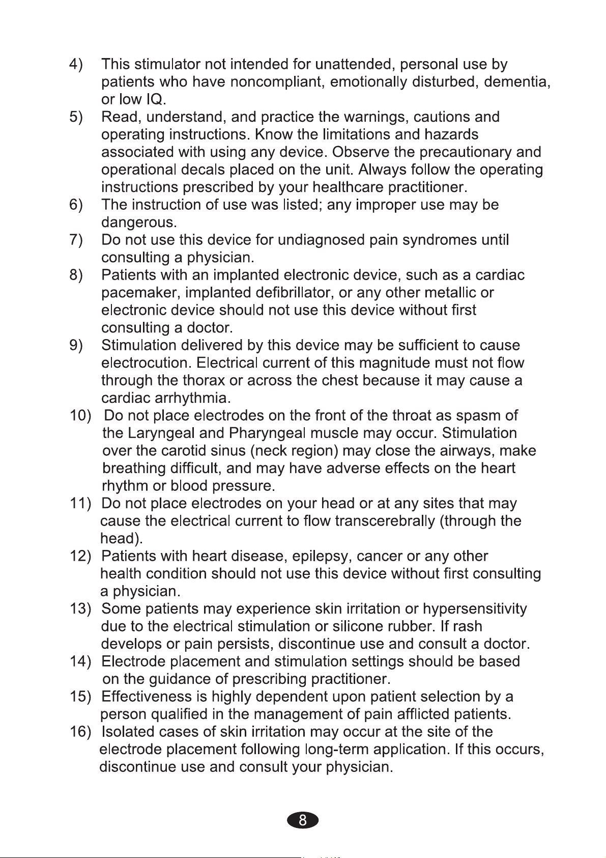
WARNINGS:
of a licensed physician.
2) The long-term effects of chronic electrical stimulation are
unknown. Electrical stimulation devices do not have any curative
value.
3) TENS is a symptomatic treatment and, as such, suppresses the
sensation of pain, which would otherwise serve as a protective
mechanism.
4) Safety has not been established for the use of therapeutic
electrical stimulation during pregnancy. Do not use during
pregnancy unless directed by your physician.
5) Electrical stimulation is not effective for pain of central origin.
6) Electronic monitoring equipment (such as ECG monitors and
ECG alarms) may not operate properly when electrical stimulation
is in use.
7) Stimulation should not be applied over the carotid sinus nerves,
particularly in patients with a known sensitivity to the carotid sinus
reflex.
Page 7
CAUTIONS:
1) Federal law (USA) restricts this device to sale by or on the order
of a physician.
2) For single patient use only.
3) Keep yourself informed of the contraindications.
Page 8
Page 9

17) The electrodes are only to be placed on healthy skin. Avoid
9
skin irritation by ensuring that good contact is achieved between
electrodes and skin.
18) If the stimulation levels are uncomfortable or become
uncomfortable, reduce the stimulation Intensity to a comfortable
level and contact your physician if problems persist.
19) This device should not be used while driving, operating
machinery, close to water, or during any activity in which
involuntary muscle contractions may put the user at undue risk of
injury.
20) Never use the device in rooms where aerosols (sprays) are
used or pure oxygen is being administered.
21) Do not use it near any highly flammable substances, gases or
explosives.
22) Do not use this device at the same time as other equipment
which sends electrical pulses to your body.
23) Do not confuse the electrode cables and contacts with your
headphones or other devices, and do not connect the electrodes
to other devices.
24) Do not use sharp objects such as pencil point or ballpoint pen
to operate the buttons on the control panel.
25) Inspect Applicator cables and associated connectors before
each use.
26) Turn the device off before applying or removing electrodes.
27) Electrical stimulators should be used only with the leads and
electrodes recommended for use by the manufacturer
28)
This device has no AP/APG protection. Do not use it in the
presence of explosive atmosphere and flammable mixture.
Adverse Reactions:
1)
Skin irritation from the electrode gel and electrode burns are
potential adverse reactions. If skin irritation occurs, discontinue
use and consult your physician.
Note: Always use electrodes that are legally marketed and sold in
the United States under 510K guidelines.
2)
If the stimulation levels are uncomfortable, reduce the stimulation
Intensity to a comfortable level and contact your physician if
problems persist.
Page 10
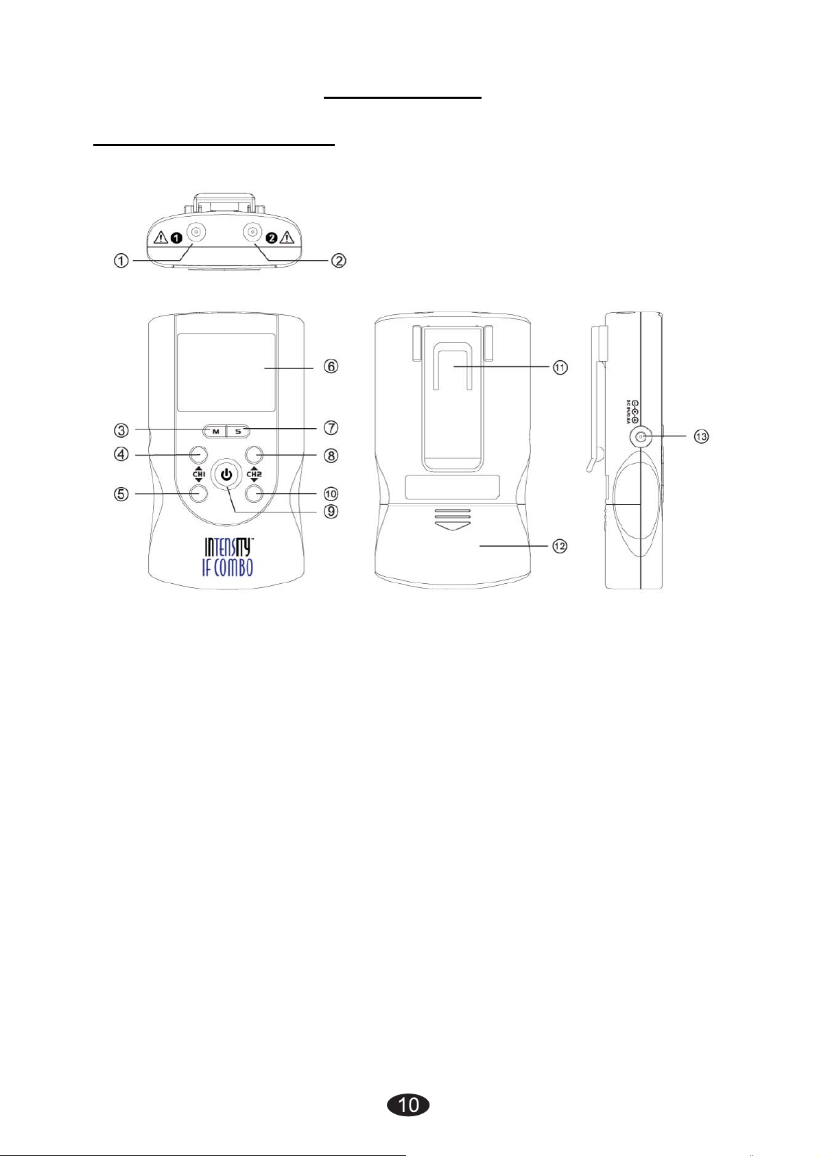
2. Presentation
2.1 Front and Rear Panel
1) Output socket: electric signal output after connection of the cable
with adhesive electrodes channel 1.
2) Output socket: electric signal output after connection of the cable
with adhesive electrodes channel 2.
3) Therapeutic mode selection (M). Stop the treatment. Exit setting
mode to the user interface.
4) Increasing the output intensity of channel 1 [▲]. To set the
application program and the parameter of the waveform in the
setting state.
5) Decreasing the output intensity of channel 1 [▼]. To set the
application program and the parameter of the waveform in the
setting state. To unlock the current treatment program.
6) LCD display: Shows the operating state of the device.
7) Parameter Selection (S): press the button to enter setting state;
you can select the difference parameters in conjunction with [▲]
and [▼].
Page 11
▲]. To set the
] button and hold for
▼]. To set the
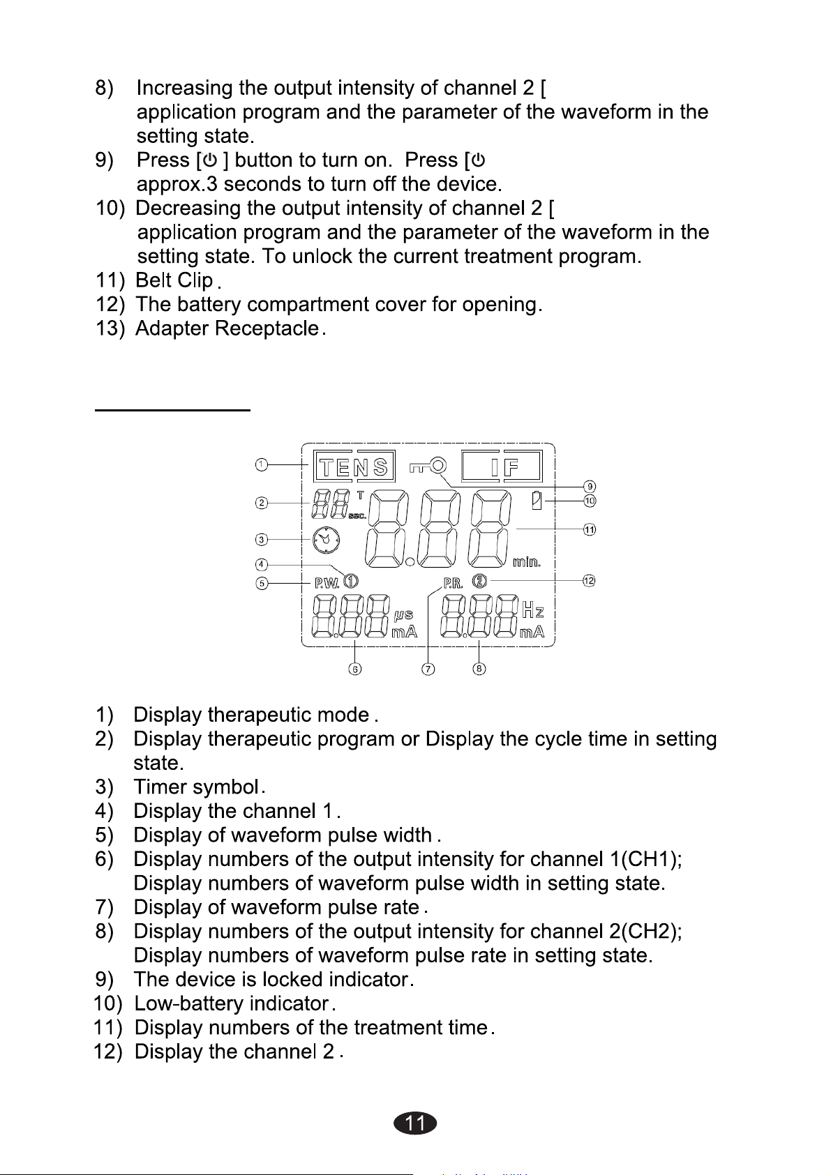
2.2 LCD display
Page 12
3. Specification
12
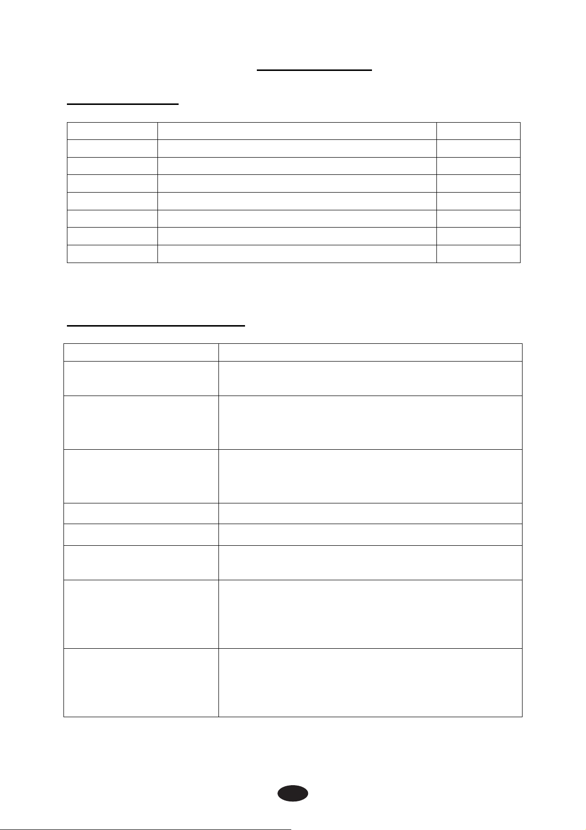
3.1 Accessories
No DESCRIPTION Q’TY
1 Electrical stimulator device 1 piece
2 Electrodes Leads 2 pieces
3 1.5” x 1.5” Adhesive Electrodes 4 pieces
4 9V Alkaline Battery, type 6LR61 1 piece
5 Instruction Manual 1 piece
6 Carrying case 1 piece
3.2 Technical information
Channel Dual, isolated between channels
Power supply
7 AC Adaptor (optional) 1 piece
9.0 V Alkaline DC -1 *6LR61 battery
Adapter output:9.0Vdc 800mA
5°C to 40°C (41℉ to 104℉)with a
Operating conditions
Storage conditions
Dimensions 4.5×2.55×0.9 inches(L*W*H)
Weight 0.28 lbs(With battery)
Tolerance
Timer
Electrode Detection
relative humidity of 30%-75%,atmospheric
pressure from 700 to 1060 Hpa
-10°C to 50°C (14℉ to 122℉)with a
relative humidity of 10%-90%,atmospheric
pressure from 700 to 1060 Hpa
There may be a ±5% tolerance of all setting
and ±10% tolerance of output of intensity.
Adjustable, from 1 to 60 minutes or
continuous, Adjustable in 1minutes each
step. Treatment time countdown
automatically.
The amplitude level will be reset to 0mA
when the amplitude level is 12mA or greater
Function
and an open circuit at either channel is
detected.
Page 13
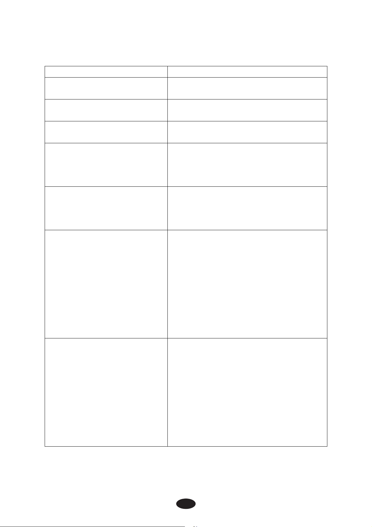
Technical specifications for Transcutaneous Electrical Nerve
13
Stimulator (TENS) mode
Waveform Mono-phase square pulse wave
Pulse amplitude
Pulse Width
Pulse Rate
Burst (P1)
Normal (P2)
Adjustable, 0~105mA peak at 1000
ohm Load each channel, 1mA/Step.
Adjustable, from 50 to 300us
microseconds, 10μS/step
Adjustable, from 1 to 150 Hz, 1
Hz/step
Burst rate: Adjustable, 0.5 ~ 5Hz;
0.1Hz/step
Pulse width adjustable, 50~300μS
Frequency fixed = 100 Hz
The pulse rate and pulse width are
adjustable. It generates continuous
stimulation based on the setting
value.
The pulse width is automatically
varied in a cycle time. The pulse
width is decreased from its original
Pulse Width Modulation
(P3)
Pulse Rate Modulation (P4)
setting to 60% in setting cycle time,
and then increased from 60% to its
original setting in nest setting cycle
time. In this program, pulse rate (1
to 150Hz), pulse width (50 to 300us)
and cycle time (5 to 30 sec) are fully
adjustable.
The pulse rate is automatically
varied in a cycle time. The pulse rate
is decreased from its original setting
to 60% in setting cycle time, and
then increased from 60% to its
original setting in nest setting cycle
time. In this program, pulse rate (1
to 150Hz), pulse width (50 to 300us)
and cycle time (5 to 30 sec) are fully
adjustable.
Page 14
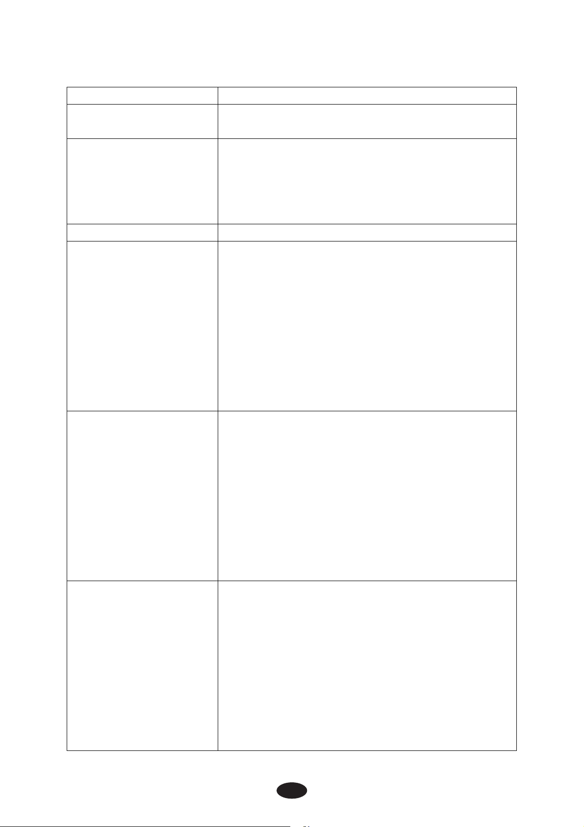
Technical specifications for Interferential (IF) mode
14
Waveform Bi-phase square pulse
Pulse amplitude Adjustable, 0~70mA peak to peak at 1000
ohm Load each channel, 1mA/Step.
Pulse Rate Channel 1 – Fundamental frequency: 4000
Hz fixed
Channel 2 – Selectable frequency: 4001 to
4150 Hz
Interference frequency: 1 to 150 Hz.
Phase Width 125μs
The pulse rate of the CH1 is fixed in
4000Hz; CH2 pulse rate is increased from
4001Hz to 4010Hz in a cycle time, and then
decreased from 4010Hz to 4001Hz in nest
P1
P2
setting cycle time. In this program, CH2
interference frequency is varied from 1Hz to
10Hz, cycle time (5 to 30 sec) is fully
adjustable.
CH 2 pulse rate=4000Hz+ Interference
frequency
The pulse rate of the CH1 is fixed in
4000Hz; CH2 pulse rate is increased from
4001Hz to 4150Hz in a cycle time, and then
decreased from 4150Hz to 4001Hz in nest
setting cycle time. In this program, CH2
interference frequency is varied from 1Hz to
150Hz, cycle time (5 to 30 sec) is fully
adjustable.
CH 2 pulse rate=4000Hz+ Interference
frequency
The pulse rate of the CH1 is fixed in
4000Hz; CH2 pulse rate is increased from
4080Hz to 4150Hz in a cycle time, and then
decreased from 4150Hz to 4080Hz in nest
setting cycle time. In this program, CH2
P3
interference frequency is varied from 80Hz
to 150Hz, cycle time (5 to 30 sec) is fully
adjustable.
CH 2 pulse rate=4000Hz+ Interference
frequency
Page 15
The pulse rate of the CH1 is fixed in
4000Hz; CH2 pulse rate is automatically
varied in a cycle time. Interference
frequency is increased from its original
setting to 60% in setting cycle time, and
P4
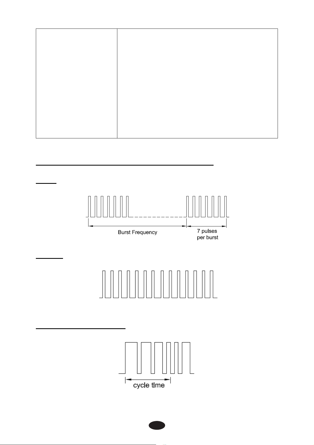
3.3 The waveforms of the stimulation programs
Burst
then decreased from 60% to its original
setting in nest setting cycle time. In this
program, CH2 interference frequency (2 to
150Hz) and cycle time (5 to 30 sec) are fully
adjustable.
CH 2 pulse rate=4000Hz+ Interference
frequency
Normal
Pulse Width Modulation
15
Page 16
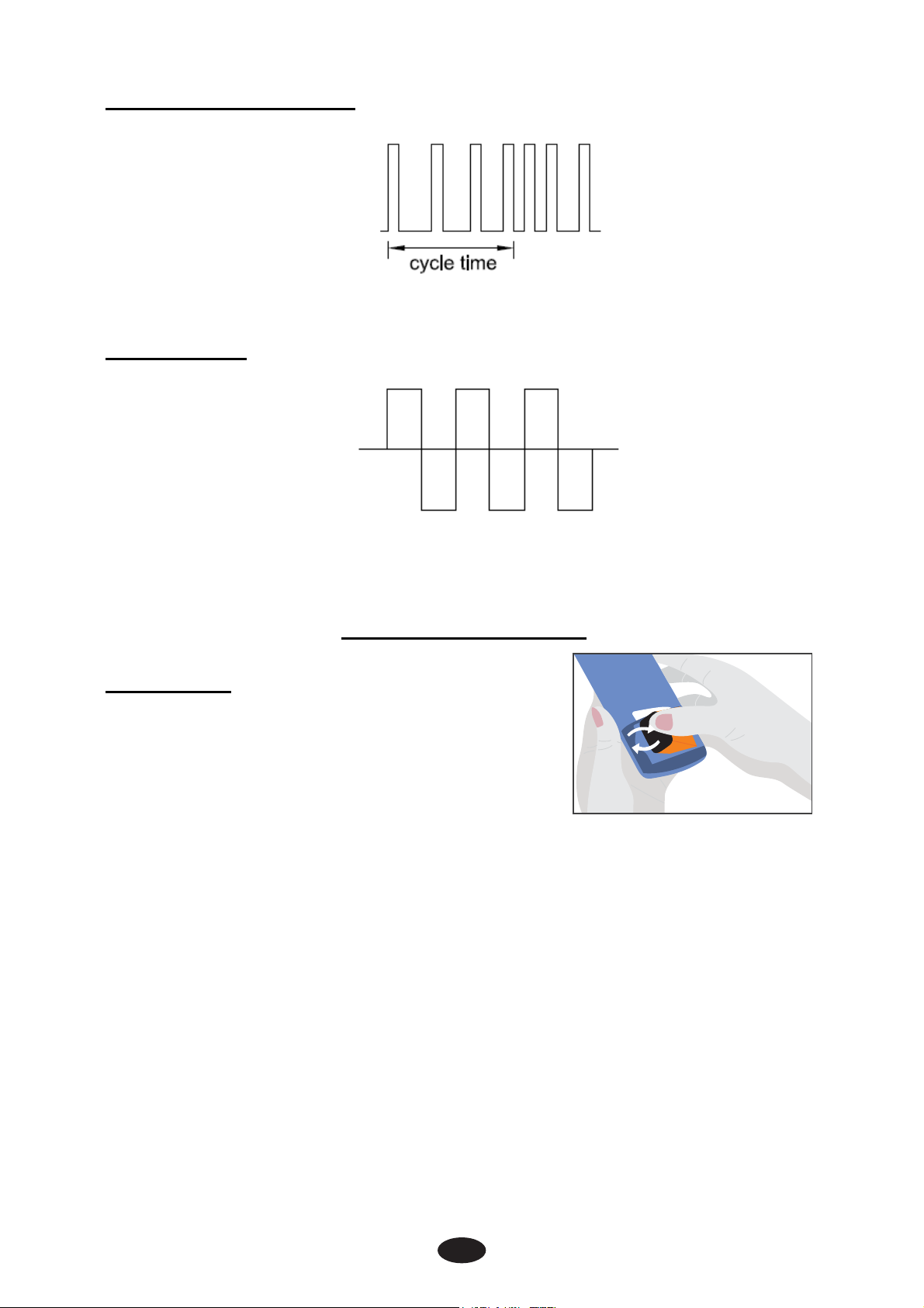
Pulse Rate Modulation
16
Interferential
4. Instruction for use
4 .1 Battery
4.1.1 Check/Replace the battery
Over time, in order to ensure the functional
safety of device, changing the battery is
necessary.
1) Slide the battery compartment cover and open.
2) Insert the 9V battery into the battery compartment.
3) Make sure you are installing the battery properly. Be sure to
match the positive and negative ends of the battery to the
marking in the battery compartment of the device.
4) Press and pull down following the direction of the arrow indicated
on the photo.
5) Replace the battery compartment cover and press to close
6) If replace the battery, you should slide the battery compartment
cover and open. Pull up the battery following the direction of the
arrow indicated on the photo. And insert the 9V battery according
to the above steps 2-5.
Page 17
4.1.2 Disposal of battery
Spent batteries do not belong in the household waste.
Dispose of the battery according to the current federal,
state and local regulations.
Caution:
1) Battery may be fatal if swallowed. Therefore, keep the battery
and the product out of the range of children, if a battery was
swallowed, consult a physician immediately.
2) If a battery has leaked, avoid contact with skin, eyes and
mucus membranes, Rinse the affected spots with lots of
clear water immediately and contact a physician right away.
3) Battery may not be charged, dismantled, thrown into fire or
short-circuited.
4) Protect battery from excess heat; Take the battery out of the
product if they are spent or in case you no longer use the
article. This prevents damage caused by leaking battery.
5) Always replace the same type battery.
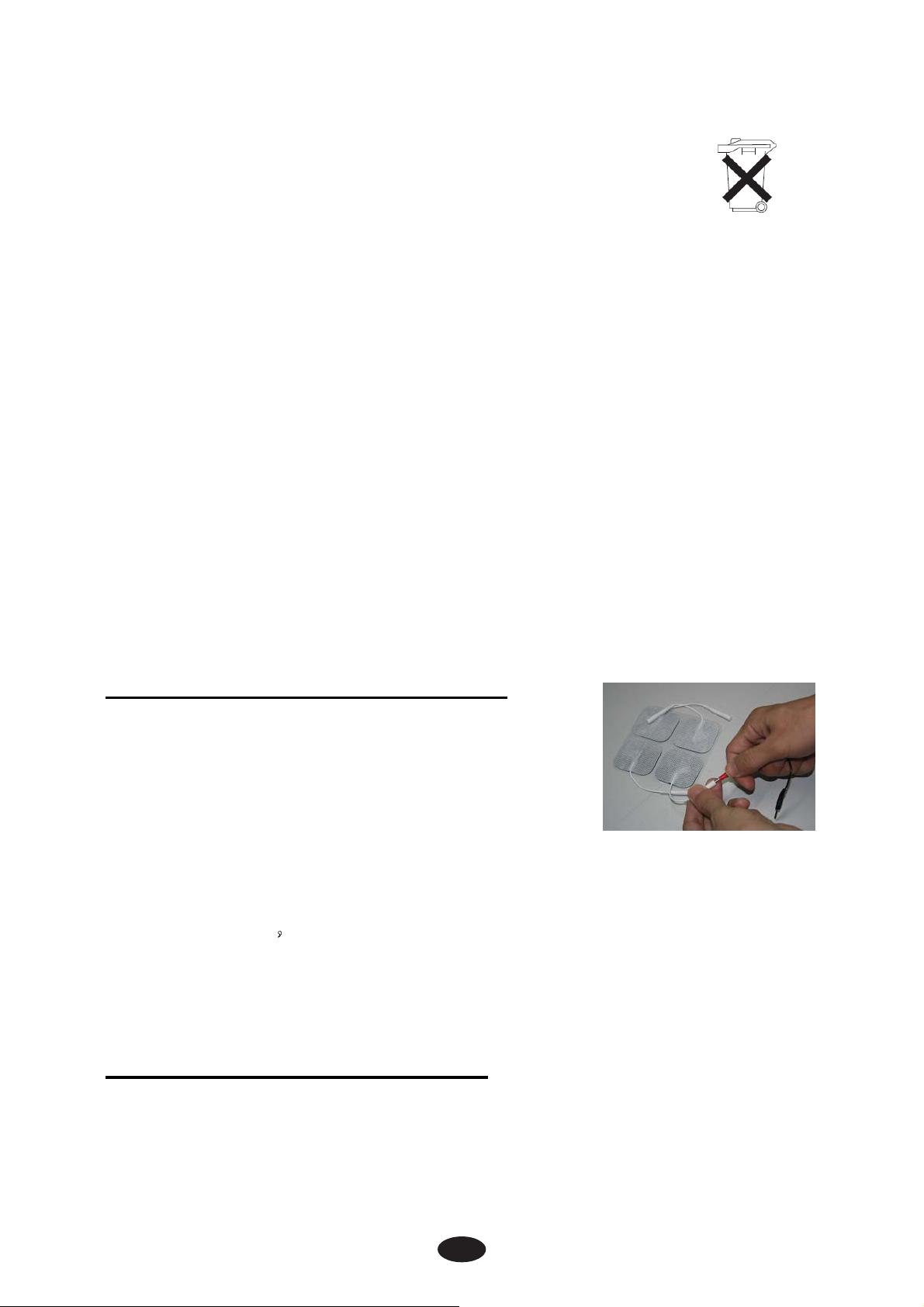
4.2 Connect electrodes to lead wires
Insert the lead wire connector into electrodes
connector (standard 0.08 inch female
connection). Make sure no bare metal of the
pins is exposed.
Caution:
Always use the electrodes with the requirements of the
IEC/EN60601-1 ,
as with CE mark, or which are legally marketed in the US under
510(K) procedure.
ISO10993-1/-5/-10 and IEC/ EN60601-1-2, such
4.3 Connect lead wires to device
1) Before proceeding to this step, be sure the device is completely
turns OFF.
17
Page 18
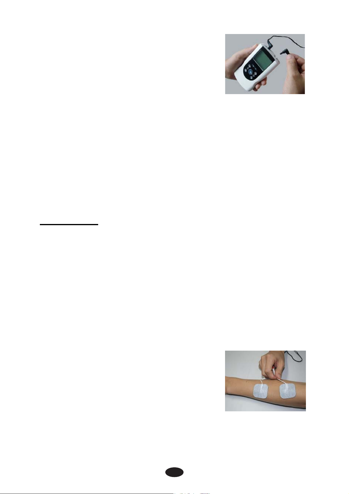
2) The wires provided with the system insert
into the jack sockets located on top of the
device.
3) Holding the insulated portion of the
connector, push the plug end of the wire
into one of the jacks (see drawing); one or
two sets of wires may be used.
4) This device has two output receptacles controlled by Channel 1
and Channel 2 at the top of the unit. You may choose to use one
channel with one pair of lead wires or both channels with two
pairs of lead wires. Using both channels gives the user the
advantage of stimulating two different areas at the same time.
Caution:
Do not insert the plug of the patient lead wire into any AC power
supply socket.
4.4 Electrode
4.4.1 Electrode options
The electrodes are disposable and should be routinely replaced
when they start to lose their adhesive nature. If you are unsure of
your electrode adhesive properties, order replacement electrodes.
Replacement electrodes should be re-ordered through or on the
advice of your physician to ensure proper quality. Follow application
procedures outlined in electrode packing, to maintain optimal
stimulation and to prevent skin irritation.
4.4.2 Place electrodes on skin
Apply electrodes to the exact site indicated by
your physician or therapist, before applying
electrodes, be sure the skin surface over
which electrodes are placed is thoroughly
cleaned and dried. Make sure the electrodes
are placed firmly to the skin and make good contact between the
skin and the electrodes. Place the electrodes over the skin; attach
them properly, firmly, and evenly.
18
Page 19

Caution:
1) Before applying the self-adhesive electrodes, it is
recommended to wash and degrease the skin, and then dry it.
2) Do not turns on the device when the self-adhesive electrodes
are not positioned on the body.
3) Never remove the self-adhesive electrodes from the skin
while the device is still turns on.
4) It is recommended that, at minimum 1.5" x 1.5" self-adhering
based, square electrodes are used at the treatment area
4.4.3 Electrode placement
The placement of electrodes can be one of the most important
parameters in achieving success with therapy. Of utmost importance
is the willingness of the physician to try the various styles of
electrode placement to find which method best fits the needs of the
individual patient.
Every patient responds to electrical stimulation differently and their
needs may vary from the conventional settings suggested here. If the
initial results are not positive, speak to your physician about
alternative stimulation settings and/or electrode placements. Once
an acceptable placement has been achieved, mark down the
electrodes sites and the settings, so the patient can easily continue
treatment.
4.5 Turn on
Before using the device for the first time, you are strongly advised to
take careful note of the contraindications and safety measures
detailed at the beginning of this manual (Safety information), as this
powerful equipment is neither a toy nor a gadget !
In order to turn on the devi
The operation page appears on the screen.
4.6 Select the Therapeutic Mode
There are two therapeutic modes available –TENS and IF. The
therapeutic mode can be selected by pressing the [M] control.
Page 20
Caution:
Consult your physician for your suitable therapeutic mode
4.7 Steps to Set a New Program
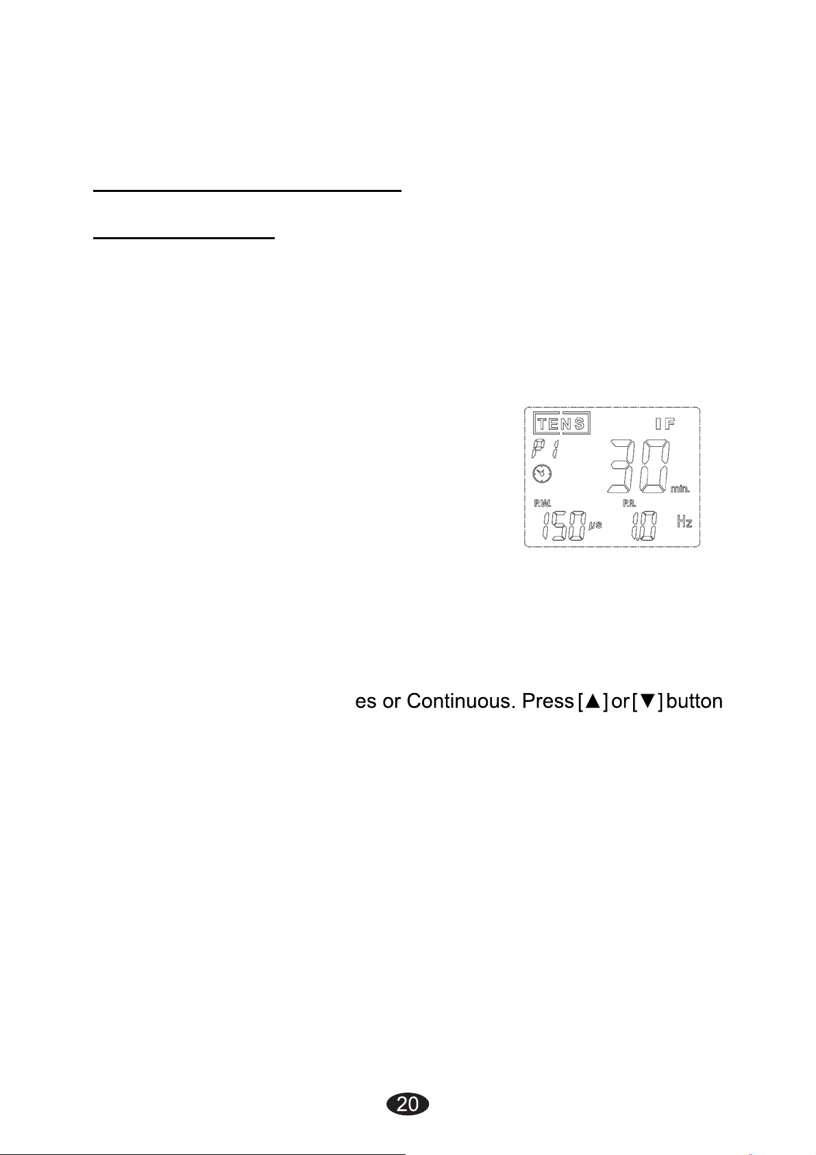
4.7.1 TENS Setting
Press the [S]button cycle to enter the setting state. The settings can
be adjusted according to the following steps:
1) Set the Therapeutic Program
There are 4 programs in TENS therapeutic mode available –Burst
(P1), Normal (P2), Pulse Width Modulation (P3), and Pulse Rate
Modulation (P4). The therapeutic program
can be selected by pressing the [▲] and [▼]
button.
2) Set Cycle Time (Optional)
Cycle time is adjustable form 5 to 30 seconds.
Only modulation has this parameter setting.
Press [S] button cycle to enter this menu, and then press the [▲] and
[▼] button to adjusting the setting.
3) Set Timer
Press [S] button cycle to enter this setting. The treatment time is
adjustable from 1 to 60 minut
control to adjust setting. You can set the timer to “Continuous” mode
by pressing the [▲] control when it shows 60 minutes. Its output will
be shut off when time is up.
4) Set Pulse Width
Pulse Width is adjustable from 50 us to 300 us. Press [S] button to
enter this menu, then press [▲] or [▼] button to adjust the setting.
5) Set Pulse Rate
Pulse rate is adjustable from 1 Hz to 150 Hz (0, 5 Hz to 5 Hz for
Burst). Press [S] button cycle to enter this menu, and then press [▲]
or [▼] button to adjust the setting.
Page 21
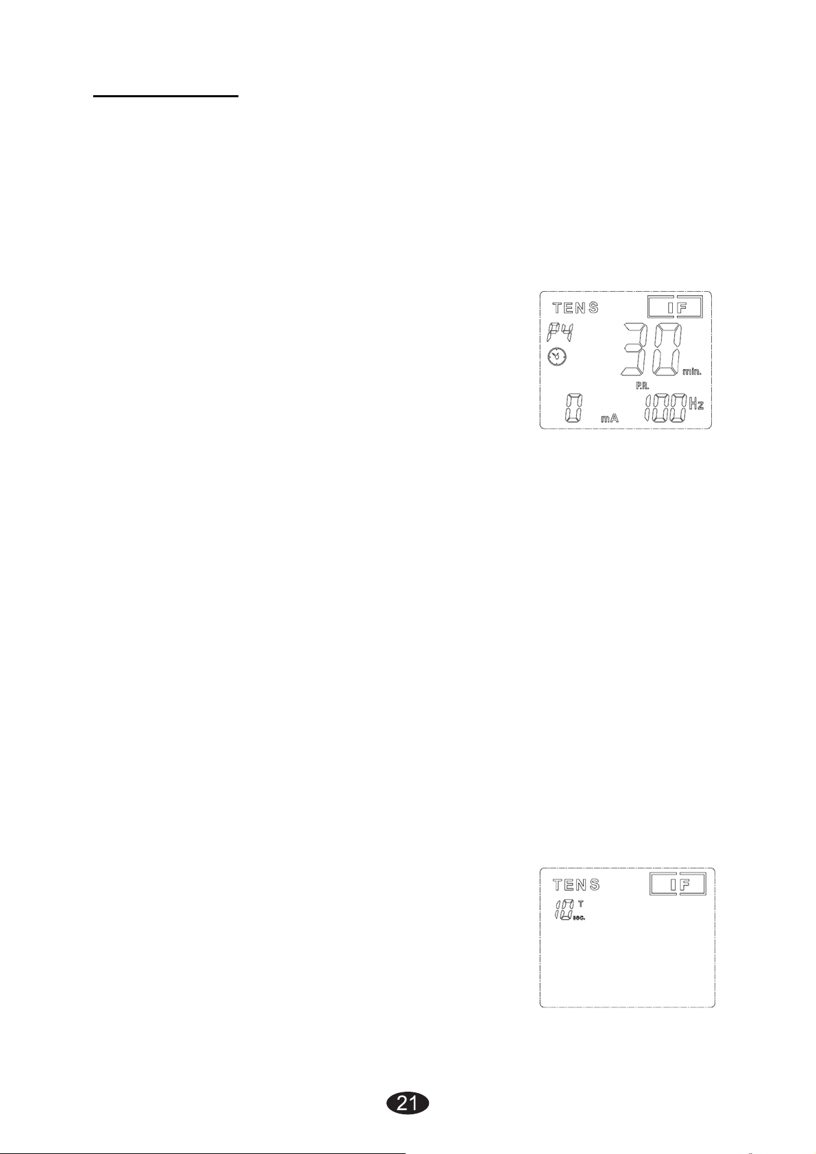
4.7.2 IF Setting
Press the [S] button to enter the setting state. The settings can be
adjusted according to the following steps:
1) Set the Therapeutic Program
There are 4 programs in IF therapeutic mode available. The
therapeutic program can be selected by pressing the [▲] and [▼]
button. The mode you selected will show up on the top of liquid
crystal display.
2) Set Timer
Press [S] button cycle to enter this setting. The treatment time is
adjustable from 1 to 60 minutes or Continuous. Press [▲] or [▼] control
to adjust setting. You can set the timer to “Continuous” mode by
pressing the [▲] button when it shows 60 minutes. Its output will be
shut off when time is up.
3) Set Interference frequency (optional)
Channel 1 has 4000 Hz fixed Fundamental frequency. Channel has
selectable frequency from 4001 to 4150 Hz; Interference frequency
is adjustable form 1 Hz to 150 Hz. Only “P4” has this parameter
setting. Press “S” button cycle to enter this menu, and then press the
[▲] and [▼] button to adjusting the setting.
4) Set Cycle Timer
Cycle time is adjustable form 5 to 30 seconds. Press [S] button cycle
to enter this menu, and then press the [▲] and [▼] button to
adjusting the setting.
Page 22

4.8 Adjust Channel Intensity
22
Press the intensity control button ([▲] and [▼]) to control the
intensity output. Slowly press the intensity button control until you
reach the setting recommended by your physician or therapist.
Repeat for the other channel, if both channels are to be used.
Caution:
1) If the stimulation levels are uncomfortable or become
uncomfortable, reduce the stimulation intensity to a
comfortable level and contact your medical practitioner if
problems persist.
2) If the electrodes no placed firmly on skin or the device has
not connected on the electrodes, the stimulator’s output
intensity surpasses 12mA, the intensity will enulls
automatically reset to 0mA.
4.9. Safety Lock Feature
The Safety Lock Feature automatically activates after there is no
operation in the panel for 30 seconds by locking out the ability to
press the buttons. This is a safety feature to prevent accidental
changes to your settings and to prevent accidental increases to the
intensity levels. You can press either one of the [▼] buttons to
unlock the device.
4.10. Stop the treatment
When you have activated the treatment timer, you can press the [M]
button or the [▼] button to control stop the treatment.
Caution:
Default state; if the button is locked, you can press only one of
the [▼] buttons to unlock, and then press the [M]button or the
[▼] button to control stop the treatment.
Page 23
4.11. Turn OFF
Press [
] button and hold for approx.3 seconds to turn OFF the
device.
Caution:
1) If there is no operation in the panel for 2 minutes in the
waiting state, the device will be turns off automatically.
2) In shutdown state, keep pressing the channel 2 [▼] first, and
then press [
]button at the same to restore factory
parameter settings
4.12. Low battery indicator
A battery symbol is shown on the display when the battery is almost
empty. As long as the stimulator is working normally you can
continue the treatment. When stimulation feels weaker than usual or
the stimulator turns off, it is time to replace the new battery.
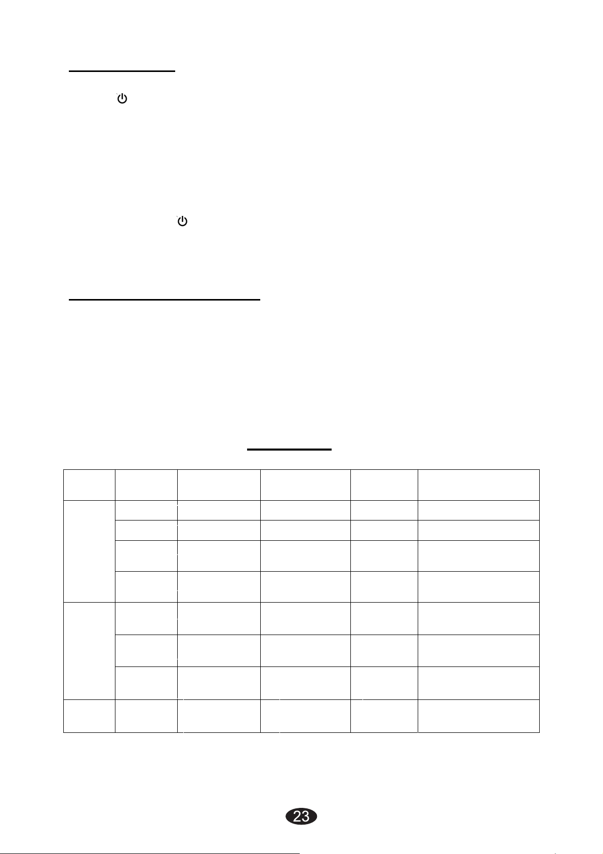
Mode Program
P1 Burst 0.5-5Hz
TENS
IF
P2 Continuous 1-150Hz
P3
P4
P1
P2
P3
P4
5. Program
Modulation
Method
Pulse width
modulation
Frequency
modulation
Frequency
modulation
Frequency
modulation
Frequency
modulation
Frequency
modulation
Frequency
1-150Hz
1-150Hz
4kHz
4001-
4001-
4080-
4001-
4010Hz
4kHz
4150Hz
4kHz
4150Hz
4kHz
4150Hz
Pulse
Width
50-
300us
50-
300us
50-
300us
50-
300us
125us 1-60min,continous
125us 1-60min,continous
125us 1-60min,continous
125us 1-60min,continous
Treat time
1-60min,continous
1-60min,continous
1-60min,continous
1-60min,continous
Page 24

6. Cleaning and Care
24
6.1 Tips for skin care
To avoid skin irritation, especially if you have sensitive skin, follow
these suggestions:
1) Wash the area of skin where you will be placing the electrodes,
using mild soap and water before applying electrodes, and after
taking them off. Be sure to rinse soap off thoroughly and dry skin
well.
2) Excess hair may be clipped with scissors; do not shave
stimulation area.
3) Wipe the area with the skin preparation your clinician has
recommended. Let this dry. Apply electrodes as directed.
4) Many skin problems arise from the “pulling stress” from adhesive
patches that are excessively stretched across the skin during
application. To prevent this, apply electrodes from centre outward;
avoid stretching over the skin.
5) To minimize “pulling stress”, tape extra lengths of lead wires to
the skin in a loop to prevent tugging on electrodes.
6) When removing electrodes, always remove by pulling in the
direction of hair growth.
7) It may be helpful to rub skin lotion on electrode placement area
when not wearing electrodes.
8) Never apply electrodes over irritated or broken skin.
6.2 Cleaning the device
1) Remove the battery from the device every time when you clean.
2) Clean the device after use with a soft, slight moistened cloth. In
case of more extreme soiling you can also moisten the cloth with
mild soapy water.
3) Do not use any chemical cleaners or abrasive agents for cleaning.
Page 25
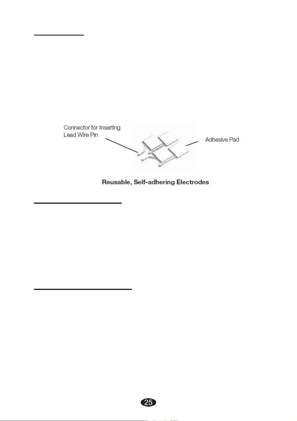
6.3 electrodes
1) Use the device only with the leads and electrodes provided by the
manufacturer. Use only the electrode placements and stimulation
settings prescribed by your physician or therapist.
2) It is recommended that, at minimum, 1.5"X1.5" self-adhering
square electrodes are used at the treatment area.
3) Inspect your electrodes before every use. Replace electrodes as
needed. Reusable electrodes may cause slight skin irritation, lose
adhesion and deliver less stimulation if overused.
To use these electrodes:
1) Attach the electrode to the lead wire.
2) Remove the protective backing from the electrode surface. Do not
throw away the protective backing because it is reused after the
treatment session has been completed.
3) Place the tacky surface to the prescribed skin area by pressing
the electrode firmly against the skin.
To remove your electrodes:
1) Lift the corner of the electrode and gently remove it from the skin.
2) Apply the protective backing to the tacky side of the electrode.
Place the electrode on the side of the protective backing that is
labeled with the word on.
3) It may be helpful to improve repeated application by spreading a
few drops of cold water over the adhesive and turn the surface up
to air dry. Over Saturation with water will reduce the adhesive
properties.
Page 26

4) Between uses, store the electrodes in the resealable bag in a cool
dry place.
Caution:
1) Do not pull on the electrode wire. Doing so may damage the
wire and electrode.
2) Do not apply to broken skin.
3) The electrodes should be discarded when they are no longer
adhering.
4) The electrodes are intended for single patient use only.
5) If irritation occurs, discontinue use and consult your
clinician.
6) Read the instructions for use of self-adhesive electrodes
before application.
7) Always use the electrodes with the requirements of the
IEC/EN60601-1, ISO10993-1/-5/-10 and IEC/ EN60601-1-2,
such as with CE mark, or are legally marketed in the US
under 510(K) procedure.
6.4 Cleaning the Electrode‘s cords
Clean the electrode cords by wiping them with a damp cloth. Coating
them lightly with talcum powder will reduce tangles and prolong the
life.
6.5 Maintenance
Maintenance and all repairs should only be carried out by an
authorized agency. The manufacturer will not be held responsible for
the results of maintenance or repairs by unauthorized persons.
The user must not attempt any repairs to the device or any of its
accessories. Please contact the retailer for repair.
Opening of the equipment by unauthorized agencies is not allowed
and will terminate any claim to warranty.
Check the unit before each use for signs of wear and/or damage.
Replace wear items as required.
Page 27
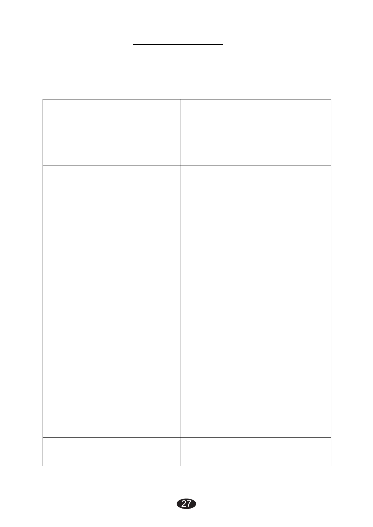
7. Troubleshooting
If your device does not seem to be operating correctly, refer to the
chart below to determine what may be wrong. Should none of these
measures correct the problem, the device should be serviced.
Problem Possible Cause Solution
Display
fails to
light
Stimulation
Stimulation
uncomfort
able.
up
is weak
is
Battery contact failure 1. Try fresh batteries.
2. Ensure batteries are inserted
correctly. Check the following
contacts:
• All contacts are in place.
• All contacts are not broken.
Electrodes
1. Dried out or
contaminated
2. Placement
Lead wires
1.Old/worn/damaged
Intensity is too high
Electrodes are too
close together
Damaged or worn
electrodes or lead wires
Electrode active area
size is too small.
Replace and re-connect
Replace
Decrease intensity.
Reposition the electrodes.
Replace.
Replace electrodes with ones that have
an active area no less than
16.0cm2(4cm*4cm).
Intermittent
output
Stimulation
is
ineffective
Lead wires
Program option in use
Improper electrode and
applicator placement
Unknown
1. Verify connection is secure. Insure
firmly.
2. Turn down the intensity. Rotate lead
wires in socket 90°. If still intermittent,
replace lead wire.
3. If still intermittent after replacing lead
wire, a component may have failed.
Call the repair department.
Some programs will seem intermittent.
This is expected.
Refer to the Program Option Controls in
the Operation section for a description
of the program option.
Reposition electrode and applicator
Contact clinician.
Page 28
8. Storage
28
1) For a prolonged pause in treatment, store the device in a dry
room and protect it against heat, sunshine and moisture.
2) Store the device in a cool, well-ventilated place
3) Never place any heavy objects on the device.
9. Disposal
Used fully discharged batteries must be disposed of in a specially
labeled collection container, at toxic waste collection points or
through an electrical retailer. You are under legal obligation to
dispose of batteries correctly.
Please dispose of the device in accordance with the legal
obligation.
Page 29
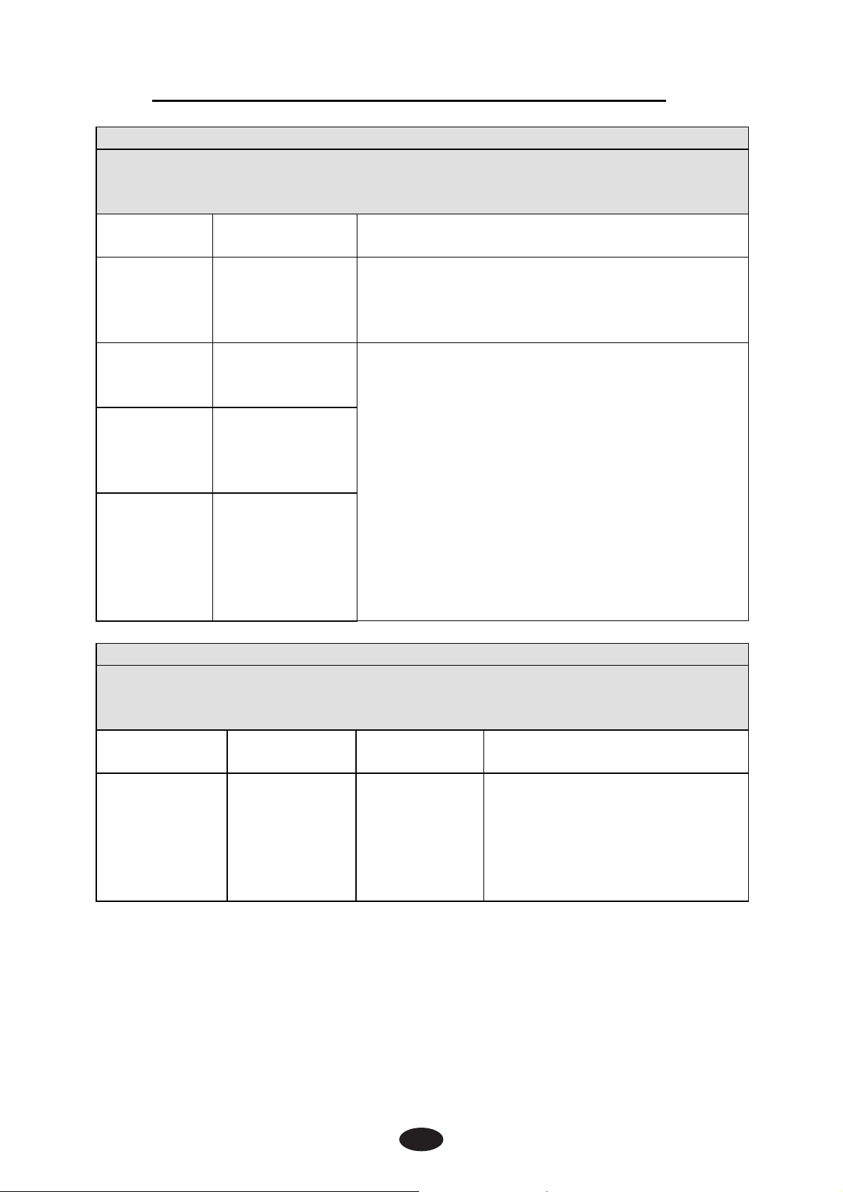
10. Electromagnetic Compatibility (EMC) Tables
29
Guidance and manufacturer’s declaration - electromagnetic emissions
The device is intended for use in the electromagnetic environment specified
below. The customer or the user assures that it is used in such an
environment.
Emissions
test
RF
emissions
CISPR 11
RF
emissions
CISPR11
Harmonic
emissions
lEC 610003-2
Voltage
fluctuations
/ flicker
emissions
lEC 610003-3
Guidance and manufacturer’s declaration — electromagnetic immunity
The device is intended for use in the electromagnetic environment specified
below. The customer or the user should assure that it is used in such an
environment.
Immunity test
Electrostatic
discharge
(ESD)
lEC 61000-42
Compliance Electromagnetic environment - guidance
The device uses RF energy only for its
Group 1
Class B
Not applicable
Not applicable
IEC 60601
test level
±6 kV contact
±8 kV air
internal function. Therefore, its RF emissions
are very low and are not likely to cause any
interference in nearby electronic equipment.
The device is suitable for use in all
establishments other than domestic and those
directly connected to the public low-voltage
power supply network that supplies buildings
used for domestic purposes.
Compliance
level
±6 kV contact
±8 kV air
Electromagnetic environment guidance
Floors should be wood,
concrete or ceramic tile. If
floors are covered with
synthetic material, the relative
humidity should be at least
30 %.
Page 30
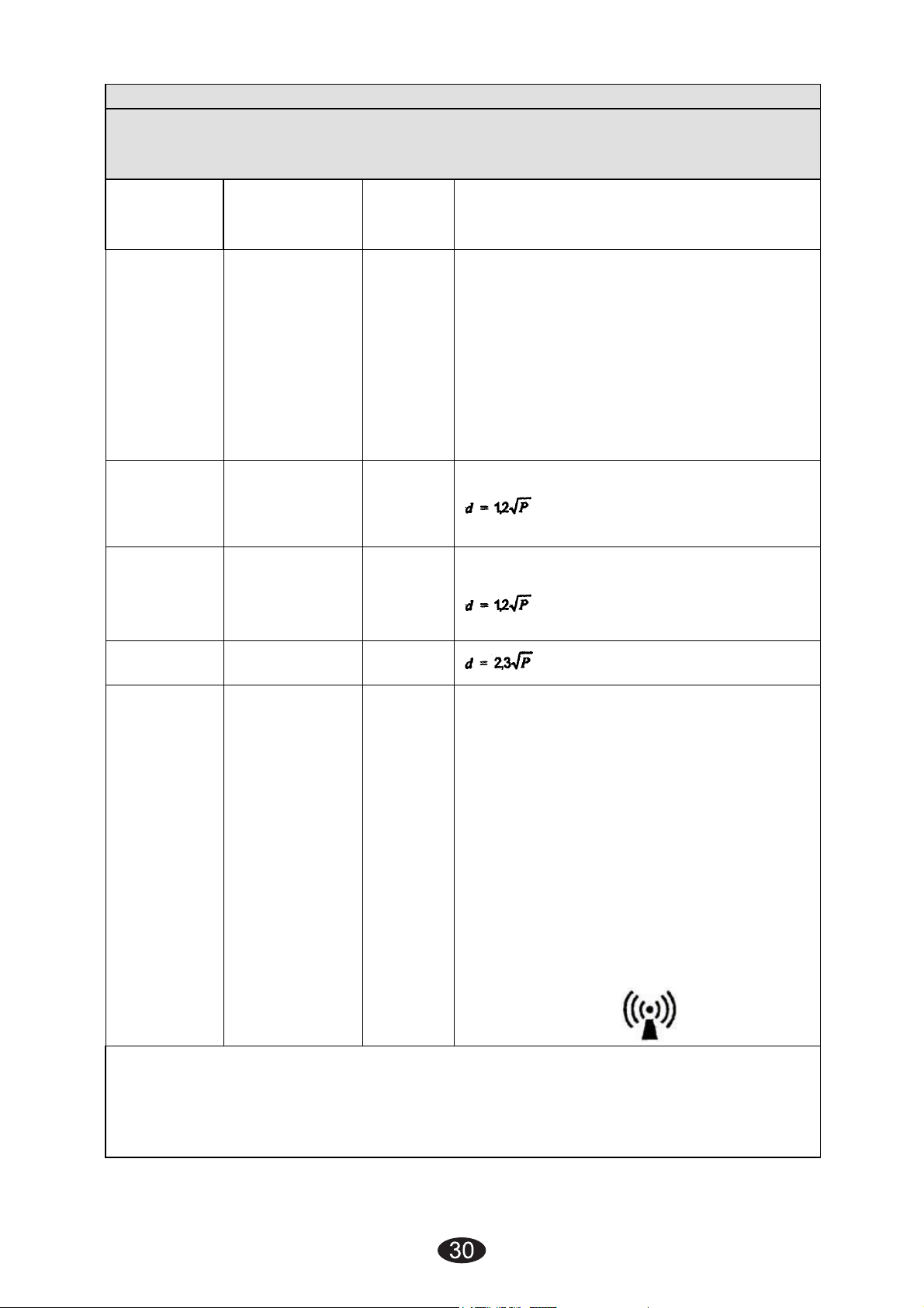
Guidance and- manufacturer’s declaration. Electromagnetic immunity
The device is intended for use in. the electromagnetic environment specified
below. The customer or the user should assure that it is used in such an
environment.
Immunity
test
IEC 60501
test level
Complia
nce
level
Electromagnetic environment guidance
Portable and mobile RF
communications equipment should be
used no closer to any part of the
device, including cables, than the
recommended separation distance
calculated from the equation
applicable to the frequency of the
transmitter.
Recommended separation distance
Conducted
RF lEC
61000-4-6
3 Vrms 150
kHz to 80
MHz
3 Vrms
Radiated
RF lEC
61000-4-3
3 V/m80 MHz
to 2.5 GHz
3 V/m
, 80MHz to 800MHz
, 800MHz to 2,5MHz
Where P is the maximum output power
rating of the transmitter In watts (W)
according to the. Transmitter
manufacturer and d Is the
recommended separation distance in
meters (m).
Field strengths from fixed RF
transmitters, as determined by an
electromagnetic site survey,
should be less than the compliance
level in
each frequency
range.
Interference may occur In the vicinity
of equipment marked with the following
symbol:
NOTE I At 80 MHz ends 800 MHz. the higher frequency range applies.
NOTE 2 These guidelines may not apply in all situations. Electromagnetic
propagation is affected by absorption and reflection from structures, objects
and people.
Page 31
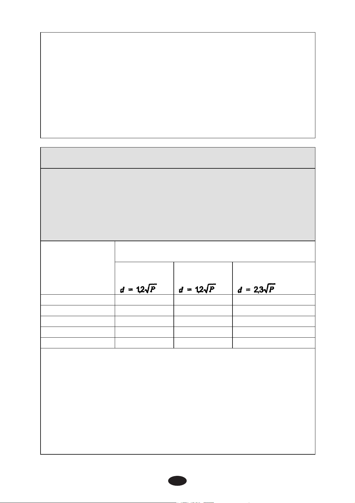
1. Field strengths from fixed transmitters, such as base stations for radio
31
(cellular/cordless) telephones and land mobile radios, amateur radio, AM and
FM radio broadcast and TV broadcast cannot be predicted theoretically with
accuracy. To assess the electromagnetic environment due to fixed RF
transmitters, an electromagnetic site survey should be considered. If the
measured field strength in the location in which the device is used exceeds
the applicable RF compliance level above, should be observed to verify
normal operation. If abnormal performance is observed, additional measures
may be necessary, such as reorienting or relocating the device.
2. Over the frequency range 150 kHz to 80 MHz, field strengths should be
less than [Vi] V/m.
Recommended separation distances between
portable and mobile RF communications equipment and the device
The device is intended for use in an electromagnetic environment in
which radiated RF disturbances are controlled. The customer or the
user of the device can help prevent electromagnetic interference by
maintaining a minimum distance between portable and mobile RF
communications equipment (transmitters) and the as recommended
below, according to the maximum output power of the
communications equipment.
Separation distance according to frequency of
Rated maximum
transmitterm
output power
of transmitter
150 kHz to
80 MHz
80 MHz to
800 MHz
800 MHz to 2,5
GHz
W
0,01 0.12 0.12 0.23
0,1 0.38 0.38 0.73
1 1.2 1.2 2.3
10 3.8 3.8 7.3
100 12 12 23
For transmitters rated at a maximum output power not listed above,
the recommended separation distance d in meters (m) can be
estimated using the equation applicable to the frequency of the
transmitter, where P is the maximum output power rating of the
transmitter in watts (W) accordable to the transmitter manufacturer.
NOTE I At 80 MHz and 800 MHz. the separation distance for the
higher frequency range applies.
NOTE 2 These guidelines may not apply in all situations.
Electromagnetic propagation is affected by absorption and
reflection from structures, objects and people.
Page 32
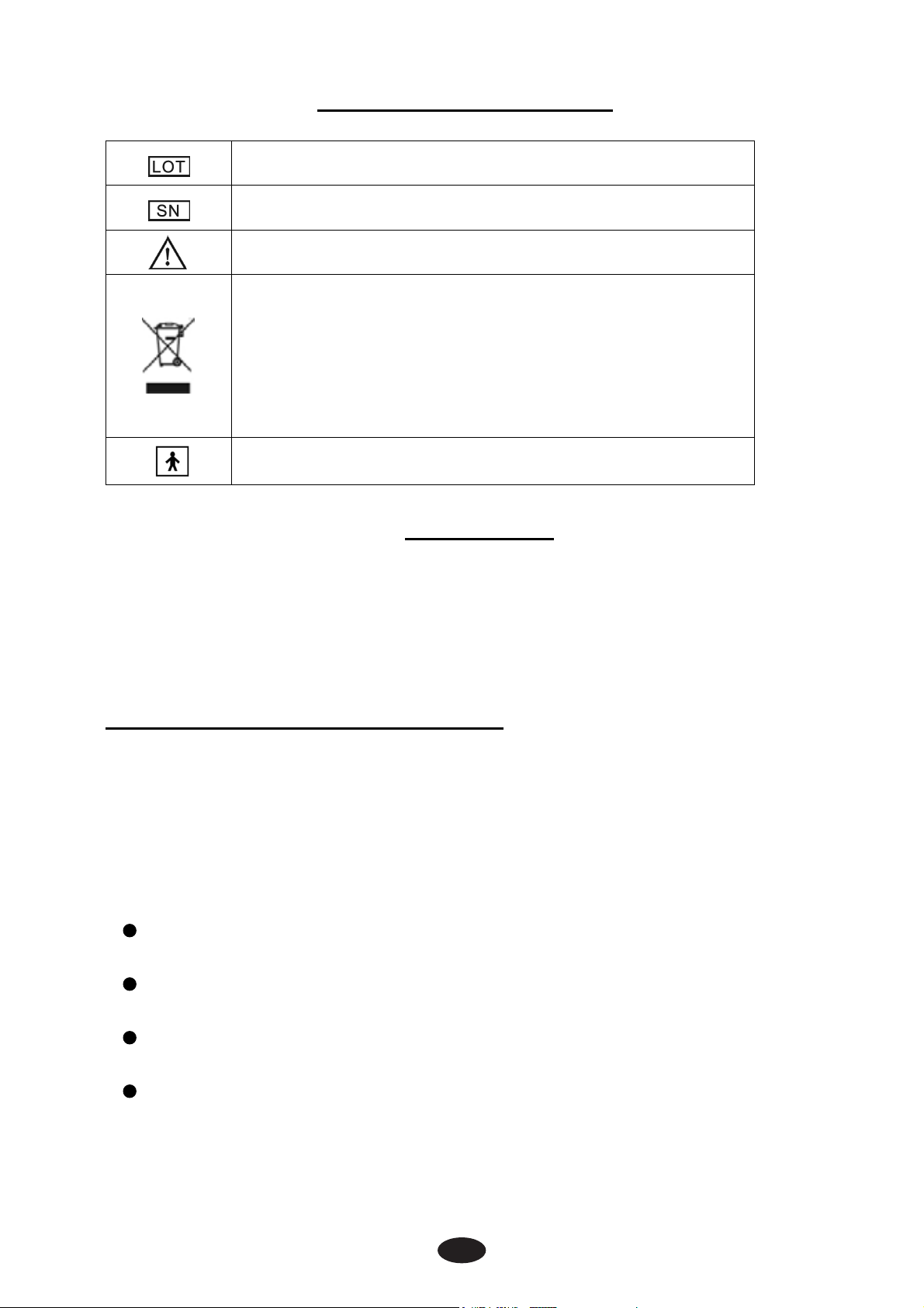
11. Glossary of Symbols
32
Batch code……..01000001
Serial number……50000001
Attention: Read the operating instruction for use!
Electrical devices are recyclable material and should not
be disposed of with household waste after their useful
life! Help us to protect the environment and save
resources and take this device to the appropriate
collection points. Please contact the organization which
is responsible for waste disposal in your area if you have
any questions.
Type BF Applied Part
12. Warranty
Please contact your dealer in case of a claim under the warranty.
If you have to send in the unit, enclose a copy of your receipt
and state what the defect is.
The following warranty terms apply:
1) The warranty period for device is one year from date of purchase.
In case of a warranty claim, the date of purchase has to be
proven by means of the sales receipt or invoice.
2) Repairs under warranty do not extend the warranty period either
for the device or for the replacement parts.
3) The following is excluded under the warranty:
All damage which has arisen due to improper treatment, e.g.
nonobservance of the user instruction.
All damage which is due to repairs or tampering by the customer
or unauthorized third parities.
Damage which has arisen during transport from the manufacturer
to the consumer or during transport to the service centre.
Accessories which are subject to normal wear and tear.
4) Liability for direct or indirect consequential losses caused by the
unit is excluded even if the damage to the unit is accepted as a
warranty claim.
Page 33

Page 34

Page 35

Page 36

Manufactured for:
Current SolutionsTM LLC
3814 Woodbury Drive
Austin,TX 78704
Ph:(800)871-7858
www.currentsolutionsnow.com
 Loading...