

Page 1
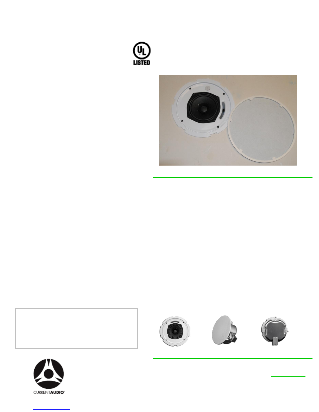
SPA525FR User’s Installation Guide
5.25” Low Profile, In-Ceiling,
Full Range Loudspeaker
The easy to install SPA525FR is a full-range ceiling
loudspeaker that incorporates a paper cone woofer with
cloth surround. It was designed for the universal USA
mandated School upgrades.
This speaker provides superior and more natural sound
for both foreground and background applications. The
Enclosed Metal design makes it the ideal choice for
typical applications in open beam attic or enclosed
ceilings. This speaker is UL 2043 Plenum rated.
The speaker grill color is white, and is a close match to
Frazee White Shadow 181. It can be painted to match
any décor. The speaker enclosure is a durable UVresistant material that allows for both indoor and outdoor
installations. The perforated powder-coated aluminum
alloy grill is long-lasting, corrosion resistant and rustfree.
Four built-in expanding transverse dog leg clamps
permit installation with or without pre-wire construction
brackets in drywall or material with thickness of 7/32” to
1 3/16”.
The included mounting kit allows for installation in
standard 2’x2’ or 2’x4’ suspended ceiling tiles. The kit
also offers support to prevent sagging. To comply with
UL, NFPA90 and NFPA70A an earthquake ring is
provided on the speaker for added support and to
prevent the unit from falling in the event of seismic
disturbances.
Electrical connection, up to 12 gauge wire, is made by
four screw down 2-pole, removable captive connector.
SPECIFICATIONS
Driver
Grill specification Fastlock Perforated aluminum with scrim cloth
Frequency
Response 75Hz – 18kHz
Impedance 8 ohms nominal
Power Handling 16 Watts Continuous & 32 Watts Program
SPL 83 dB 1W/1m
Diameter x Depth 10 3/8“ (263mm) x 4" (102mm)
Cutout Diameter 8.94" (227mm)
Product Weight
(each) 5 lbs (2.3kg)
Shipping Pack
Dimensions 2 pair
(weight)
5.25" Paper Cone, Cloth Surround
22" x 13" x 12" (20 lbs) 10kg with Mounting
Hardware
Part Number 99003
Manual URL www.currentaudio.com
Accessories - NC6CB New Construction Bracket
- Volume Control
www.currentaudio.com
1830 John Towers Avenue El Cajon, CA 92020 Sales 866-927-7181
©2009 Current Audio LLC
RPA 92020Rev2 04/11
Page 2
SPA525FR User’s Installation Guide
Packaging and Enclosed Parts
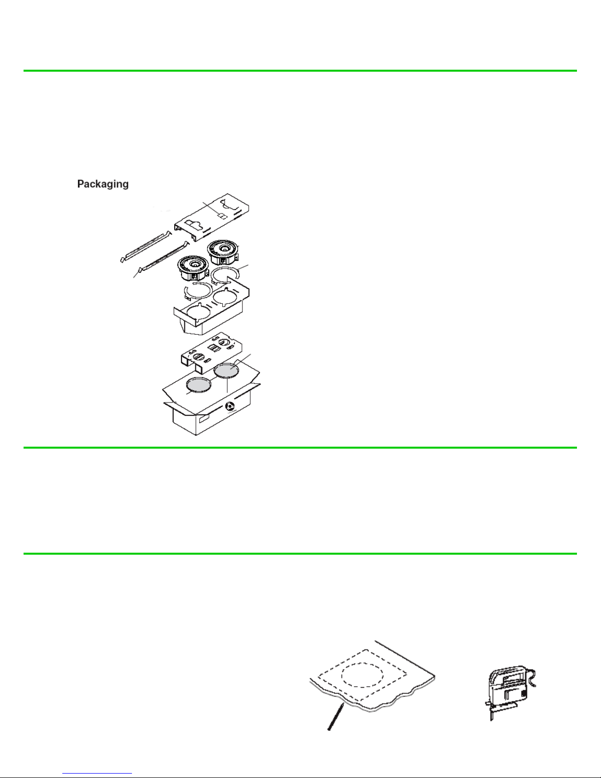
The following diagram shows all of the included parts for assembly and installation. Please inspect your pack for damaged or missing
parts. Notify your supplier if any discrepancies occur.
Rough-in
Mounting
Screws
Only simple hand tool are required for assembly and
installation.
Required tools: #2 Phillips screwdriver, Small Flathead
slotted screwdriver with a
1/8” inch blade or smaller, Drywall Hand saw. A saber may
be requires if you are cutting into plywood.
V-rails (4)
(2 pc each
speaker)
Speakers
C-ring
Rough-ins
Fastlock
Speakers
Grilles
Painting the Speaker Grille
Tear along the smaller perforated line of the cutout template marked as a paint shield. Push it into the front baffle of the speaker. Paint the
front.
Remove the paint shield after the paint has dried.
Drywall Ceiling Installation
1
Take the cutout template from the packaging box and
punch out along the larger perforated circle.
Place the cutout template against the ceiling and
and trace along the inside circle. Carefully cut out
the ceiling material along the circle.
Cut Material
Trace Template
Rev 92020Rev1 06/09
Page 3
SPA525FR User’s Installation Guide
2
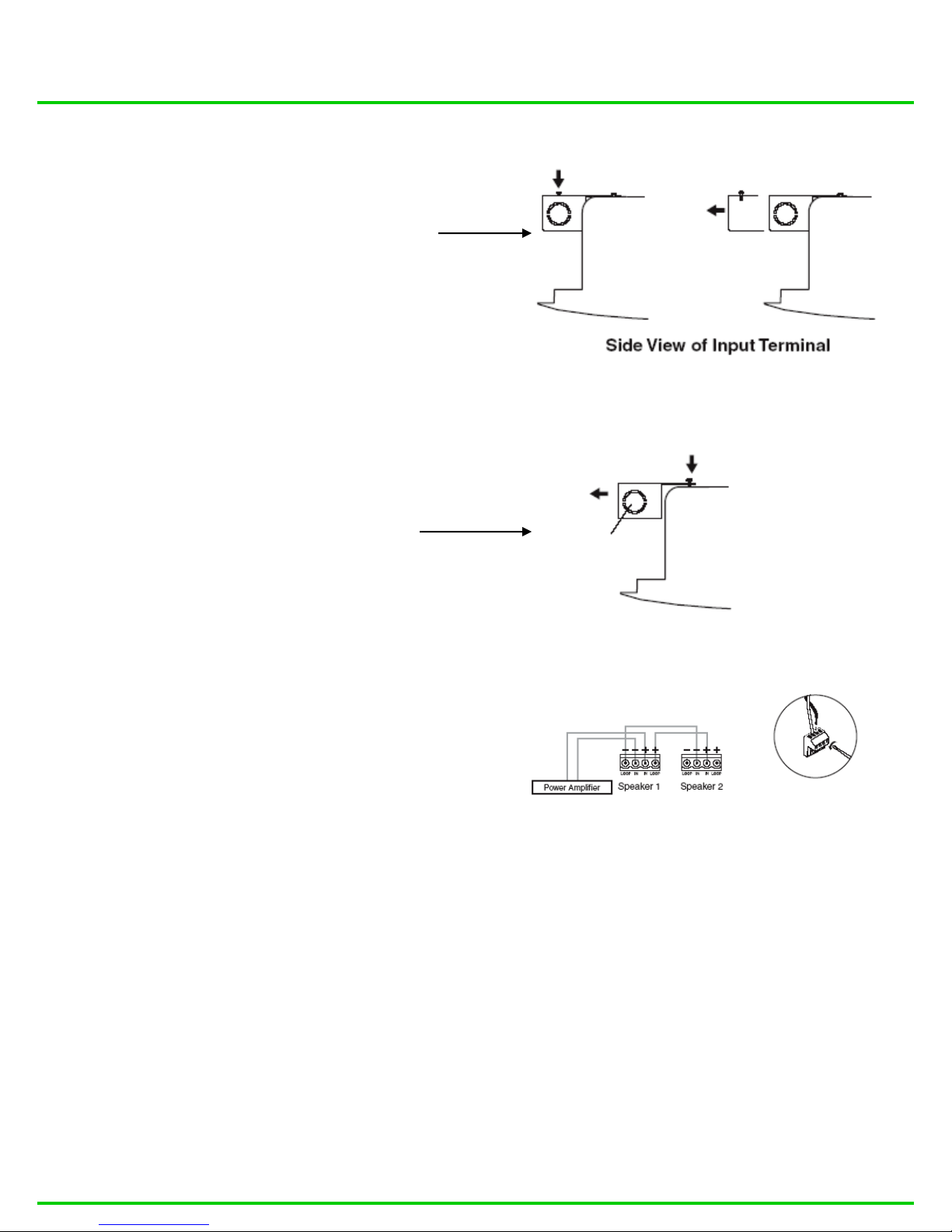
The side terminal cover, as shown in step 3f, must first
be removed before wiring the speaker.
Loosen the single top screw of the side terminal cover
and pull the side terminal cover straight out.
See the illustration below.
Loosen
Screw
Side
Terminal
cover
3
a) Remove the top terminal cover (see illustration
in step 3f) by loosening (do not remove) both top
screws, sliding the top terminal cover away from the
Screws, and removing the cover, as shown here.
b) Remove the knockout (s) from the top terminal
cover depending on the direction from which the
conduit (s) will be entering and/or leaving the
cover.
c) Insert the conduit (s) into the knockout opening (s)
and secure the conduit to the cover with the locking
nut.
NOTE: Installation in a plenum-rated environment
Requires plenum rated wire gauge of 14 AWG to
18 AWG.
Loosen two
Screws
Top Terminal
Cover
Knockout
To connect speakers in parallel, see the wiring
diagram below.
Z-Pole Captive
Screw Connector
e) Bring the speaker up to the bottom of the hole in the
ceiling.
d) Pull the speaker wires from the conduit, strip 0.2”
(5 mm) from the wire ends (do not tin the wires), and
secure the wires into the 4 screw z-pole removable
captive connector.
RPA Rev 92020Rev2 04/11
Page 4
SPA525FR User’s Installation Guide
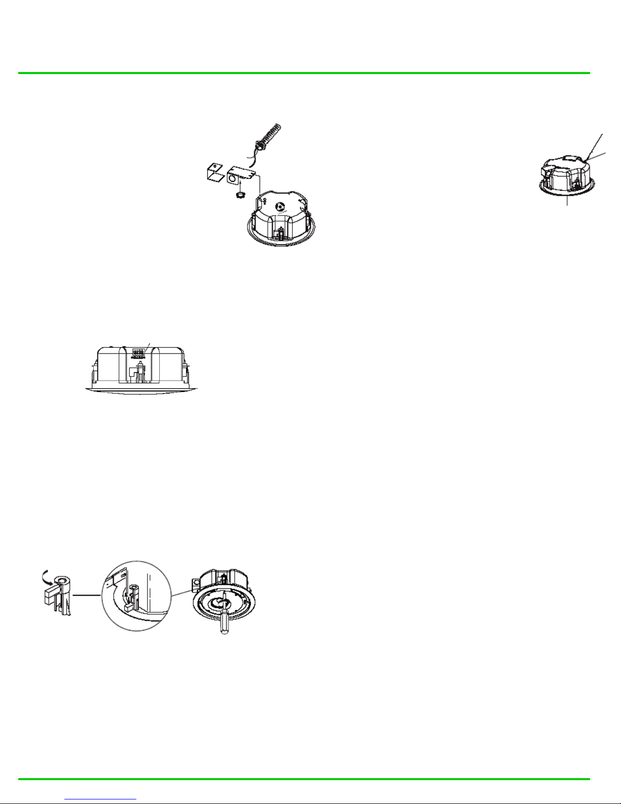
f) Plug the wired connector from step 3d into the
speaker’s audio input connector. Secure the top
terminal cover with the two top screws that were
loosened in step 3a; hook the side terminal cover
to the top terminal cover; and secure the side
terminal cover in place with the screw that was
loosened in step 2.
NOTE: Installation in a plenum-rated environment
Requires plenum rated wire gauge of 14 AWG to
18 AWG.
4-pole Captive Screw Connector
Front View of Input Terminal
Side
Terminal
Cover
4
See Note Below.
Top Terminal
Cover
Align the Fast Cock Grill Tabs with the speaker
detents. Twist clockwise until the tabs lock with the
Detent.
NOTE: Grill must be rotated enough to ensure it is
locked in place to prevent the grill from loosening.
Suspended Ceiling Installation
1
Remove the ceiling tile where
the speaker is to be installed.
2
Use the cutout template to trace the
hole on the tile, then cut out the hole
(see step 1 on page 3)
3
4
Bring the speaker cable
through the hole in the cut
tile, then reinstall the tile.
Remove the adjacent tile.
Place the 2 V-rails
and 1 C-ring across the tile
Seismic Tab &
Support Line
Loosen the four screws on the front baffle ½ turn
(counterclockwise). Insert the speaker in the ceiling
hole, then tighten the screws (clockwise) until the
dog legs clamp the speaker to the ceiling. See
below.
CAUTION: Do not overtighten screws.
Dog Leg
5
Connect a secondary support line from the seismic
tab to a secure support point according to local
building codes.
5
Connect the wires to the
speaker terminal
connector. (see step 3
Drywall Ceiling
Installation.)
7
Connect a secondary
support line from the
seismic tab to a secure
support point.
(See Step 5 of Drywall
Ceiling Installation)
8
where speaker is to be
installed. Bring the speaker
up to the bottom of the hole in
the ceiling tile.
6
Loosen the four screws on
the front baffle ½ turn
(counterclockwise).
Then tighten the screws
(clockwise) until the dog
legs clamp the speaker
to the ceiling.
CAUTION: Do not
overtighten screws.
Install the grille (see step 5 of Drywall Ceiling Installation).
Rev 92020Rev2 04/11
 Loading...