

Page 1

Wireless Thermostat (WTS10)
Installation Instructions
The Daintree Networks Wireless Thermostat (WTS10) operates seamlessly within the ControlScope® wireless building
control platform. The WTS10 is a low voltage wireless commercial programmable thermostat that can connect to any
single or multi-stage conventional or heat pump HVAC system. As part of the ControlScope system and using industry
standard ZigBee® wireless communications, the WTS10 can be managed and programmed from any location using the
ControlScope Manager (CSM) web application, eliminating the need for on-site, manual thermostat adjustment.
Installation Process
If this is a new thermostat installation, locate the
thermostat 4 to 5 feet above the floor in accordance
with applicable building codes. Install in a location that
provides good airflow characteristics and avoid areas
behind doors, near corners, air vents, direct sunlight, or
heat generating devices. Installation in these areas could
impact thermostat performance. Wiring must conform
to all building codes and ordinances as required by local
and national code authorities having jurisdiction for this
installation.
1. Always turn off power to the air conditioning and/or
heating system prior to installing thermostat.
2. Determine the HVAC equipment type. Note to Installer:
Circle the type of equipment and giive this information to
the commissioning agent:
A. 1 Stage Heat / 1 Stage Cool Conventional System
B. 2 Stage Heat / 2 Stage Cool Conventional System
C. 3 Stage Heat / 2 Stage Cool Conventional System
D. 1 Stage Heat / 1 Stage Cool Heat Pump System
(without Auxiliary Heating)
E. 2 Stage Heat / 1 Stage Cool Heat Pump System
(with Auxiliary Heating)
F. 2 Stage Heat / 2 Stage Cool Heat Pump System
(without Auxiliary Heating)
G. 3 Stage Heat / 2 Stage Cool Heat Pump System
(with Auxiliary Heating)
3. Refer to the Wiring: Thermostat Terminals section to
determine the number of wires necessary to install this
thermostat with your system.
• A common connection between the HVAC unit and
the thermostat “C” terminal is required.
• When replacing an existing thermostat, and before
disconnecting any wires, mark each wire
connected to the existing thermostat with the
terminal letter to which it is connected.
• Make sure the disconnected wires do not slip back
through the wall opening; anchor them outside the
wall opening.
4. Ensure that power to the air conditioning and heating
systems is turned off.
5. Mount the WTS10 thermostat.
A. Remove the thermostat front body from the base.
B. Guide thermostat wires through the center opening
in the base. Anchor them so they do not slip back
into the wall.
C. Hold the thermostat base against the wall in the
desired thermostat location.
D. Mark placement of mounting holes as appropriate.
E. Remove thermostat base from the wall. Install wall
anchors as required at the mounting hole locations.
F. Re-insert the wires through the center opening on
the base. Anchor them so they do not slip back into
the wall.
G. Fasten the base to the wall using the supplied #6
screws into the wall anchors.
DT103 (Rev. 12.8.17)
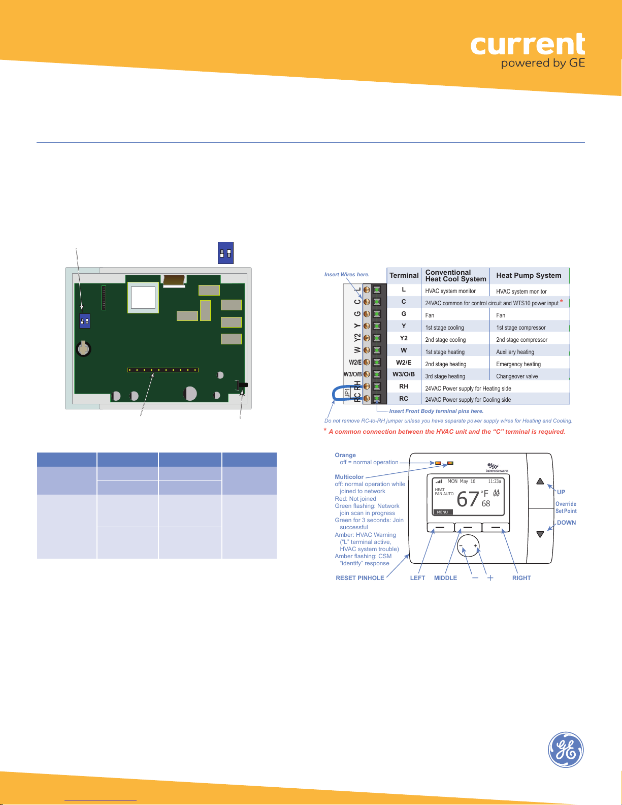
6. Refer to Wiring: Thermostat Terminals and wire the
terminals on the thermostat base to the attached HVAC
equipment.
1
Page 2
Wireless Thermostat (WTS10)
• When replacing an exisng thermostat, before disconnecng any wires, mark
each wire connected to the exisng thermostat with the terminal leer to
which it is connected.
• Make sure the disconnected wires do not slip back through the wall opening;
anchor them outside the wall opening using a pencil or screwdriver.
A. Remove the thermostat front body from the base.
B. Guide thermostat wires through the center opening in the base. Make sure
they don’t slip back into the wall.
C. Hold the thermostat base against the wall in the desired thermostat locaon.
D. Mark placement of mounng holes as appropriate.
E. Remove thermostat base from the wall. Install wall anchors as required at the
mounng hole locaons.
F. Re-insert the wires through the center opening on the base. Anchor them so
they don’t slip back into the wall.
G. Fasten the base to the wall using the supplied #6 screws into the wall anchors.
base to the aached HVAC equipment.
This is used to set the thermostat for operaon with the HVAC system.
RC RH W Y2 Y G C L
W2/E
W3/O/B
RC RH W Y2 Y G C L
W2/E
W3/O/B
JP1
Insert Front Body terminal pins here.
Insert Wires here.
L
C
G
Y
Y2
W
W2/E
W3/O/B
RH
RC
Terminal
Conventional
Heat Cool System
HVAC system monitor
24VAC common for control circuit and WTS10 power input
*
Fan
1st stage cooling
2nd stage cooling
1st stage heating
2nd stage heating
3rd stage heating
24VAC Power supply for Heating side
24VAC Power supply for Cooling side
HVAC system monitor
Fan
1st stage compressor
2nd stage compressor
Auxiliary heating
Emergency heating
Changeover valve
Heat Pump System
Do not remove RC-to-RH jumper unless you have separate power supply wires for Heating and Cooling.
*
A common connection between the HVAC unit and the “C” terminal is required.
UP
DOWN
MIDDLELEFT RIGHTRESET PINHOLE
Orange
off = normal operation
Multicolor
off: normal operation while
joined to network
Red: Not joined
Green flashing: Network
join scan in progress
Green for 3 seconds: Join
successful
A
mber: HVAC Warning
(“L” terminal active,
HVAC system trouble)
A
mber flashing: CSM
“identify” response
FAN AUTO
HEAT
MENU
MON May 16
11:23a
67
F
°
68
Override
Set
Point
Installation Process continued
7. On the thermostat body, locate switch SW1 on the
circuit board as shown below. This is used to set the
thermostat for operation with the HVAC system.
XUYXXK
XUYXXK
XUK
E/B STD
G/O
OXVUIZ
OXVUIZ
ON
1 2
XUYXXK
XUYXXK
XUK
XUYXXK
XUYXXK
XUK
Reset PinFront Body Terminal Pins: Align with terminal block on base
STD (on, up)
HP (off, down)
SW1: Set System Type - Example shows
E/BONSTD
ON
SW1
1 2
G/O
HP
8. Set switches as appropriate for your system:
System Type Source Switch #1 Switch #2
Conventional
Heat Pump
9. Attach the thermostat front body to the base, being
careful to align the terminal pins on the front body with
the terminal block on the base.
10. Restore system power.
11. Test the thermostat according to the procedure in the
Test section for the connected HVAC system.
Switch #1: Off (G/O) - Gas
Switch #2: On (STD) - Conventional
XUY 0V B0AB MKLXXK
XUY 0V B0AB MKLXXK
XUYXXK
NB0 SMXUY 0V B0AB MKLX XK
XUK
OXVUIZ
L C G Y Y2 W W2/C W3/O/B RH RC
XUYXXK
XUYXXK
XUYXXK
XUYXXK
XUK
XUK
Electric E/B (on, up)
Gas G/O (off, down)
Heat
Changeover
Valve
Cool
Changeover
Valve
E/B (on, up)
G/O (off, down)
Wiring: Thermostat Terminals
To prevent electrical shorts and potential damage to the
thermostat, ensure all of the base wire connections are
secure and are not touching any other terminal. Push any
excess wire back into the wall cavity and insulate the wire
opening with suitable material.
HP
OXVUIZ
OXVUIZ
OXVUIZ
12. Set the time and date on the thermostat. See the
“Keypad Operation Guide.”
13. Review the default program schedules in the “Keypad
Operation Guide” and adjust as necessary.
14. When you are ready to commission the ControlScope
wireless network, see Joining the ZigBee Wireless
Network.
2
Page 3

Wireless Thermostat (WTS10)
Testing
WARNING! Read BEFORE Testing
• Do not short across terminals on the gas valve or
at the heating or cooling system control board to
test the thermostat installation. This could damage
the thermostat and void the warranty.
• Do not select COOL mode if the outside temperature
is below 50° F (10° C). This could damage the
controlled cooling system and cause personal
injury.
• Ensure the power supply is correct and the display is
reading current room temperature.
Test for Conventional System
1. Press and hold down the (LEFT) button, then
momentarily press Reset pinhole. The screen will go blank.
When you see INSTALLATION MODE release (LEFT) button.
All the outputs are turned off.
2. “HVAC: ELEC Heat/Cool” indicates SW1 is set for Electric
Conventional System. “HVAC: GAS Heat/Cool” indicates
SW1 is set for Gas Conventional System. If the display is
incorrect, please review the SW1 switch positions.
3. “FAN” is highlighted. Press the
FAN output (ON/OFF). After testing the FAN output, it is
best to keep the FAN output ON to test other outputs.
+ button to toggle the
9. Press the (DOWN) button to highlight “Stage3”. Press
the + button to toggle the HEAT stage 3 output (ON/OFF).
10. Press the Reset pinhole to stop the INSTALLATION
MODE.
Test for Heat Pump Systems
1. Hold the (LEFT) button, then momentarily press
Reset pinhole. The screen will go blank. When you see
INSTALLATION MODE release the (LEFT) button. All the
outputs are turned off.
2. “HVAC: Heat Pump <O>” indicates SW1 is set for cool
changeover valve O. “HVAC: Heat Pump <B>” indicates
SW1 is set for heat changeover valve B. If the display is
incorrect, please review the SW1 switch positions.
3. The setting for “STAGE” is highlighted. Press the +
button to scroll through the selections: “1H1C or 2H/1C”
and “2H2C or 3H2C.” When the desired STAGE selection
is highlighted, press the (DOWN) button to enter your
selection and advance to the FAN selection.
4. Press the + button to toggle the FAN output (ON/OFF).
Keep the FAN output ON while testing the other outputs.
5. Press the (DOWN) button to highlight the setting for
“COOL: Stage1”. Press the + button to toggle the COOL
stage 1 output (ON/OFF). For a 2-Stage cooling system,
press the (DOWN) button to highlight “Stage2”. Press the
+ button to toggle the COOL stage 2 output (ON/OFF).
4. Press the (DOWN) button to highlight COOL: “Stage1”.
Press the + button to toggle the COOL stage 1 output
(ON/OFF).
5. Press the (DOWN) button to highlight “Stage 2”. Press
+ button to toggle the COOL stage 2 output (ON/OFF).
6. Press the (DOWN) button to go to the HEAT test. All
cool outputs are turned off; the fan output will be turned
off for a GAS System, and the fan output will keep current
status for an Electric System.
7. HEAT: “Stage1” is highlighted, press the + button to
toggle the HEAT stage 1 output (ON/OFF).
8. Press the (DOWN) button to highlight “Stage2”. Press
the + button to toggle the HEAT stage 2 output (ON/OFF).
6. Press the (DOWN) button to go to the HEAT test. All
cool outputs will be turned off, and the fan output will
keep it’s current status. HEAT: “Stage1” is highlighted.
Press the + button to toggle the HEAT stage 1 output
(ON/OFF). For a 2 or 3-Stage heat system, press the
(DOWN) button to highlight “Stage2”. Press the + button
to toggle the HEAT stage 2 output (ON/OFF). For a 3-Stage
heat system, press the (DOWN) button to highlight
“AUX”. Press the + button to toggle the Auxiliary Heating
output (ON/OFF). Press the (DOWN) button to highlight
the “EMER” setting. Press the + button to toggle the
EMERGENCY output (ON/OFF).
7. Press the Reset pinhole to stop the INSTALLATION
MODE.
3
Page 4

Wireless Thermostat (WTS10)
LED Operation
The WTS10 has two LEDs above the display. Upon powerup the LEDs cycle on and off briefly as the thermostat
goes through its start-up routine. After the start-up
routine is complete, the LEDs operate as described in the
tables below.
Left (orange) LED Description
Not Lit
Orange, flashing
Right (multicolor) LED Description
Not Lit
Red, solid
Green, flashing
Green, solid for 3 seconds
Amber, solid
Amber, flashing
Normal operation.
Bootloader reprogramming MCU after OTA
firmware update performed successfully.
Normal operation while joined to ZigBee
network.
Thermostat has not joined a ZigBee
network.
Thermostat is scanning for a network to
join.
Thermostat has joined a ZigBee network.
HVAC system warning: 24VAC is detected
at thermostat’s L terminal.
Thermostat is responding to an “Identify”
command from CSM.
Joining the ZigBee Wireless Network
After successfully completing the Installation Test the
WTS10 is ready to communicate with the Daintree
Wireless Area Controller (WAC) and be commissioned and
configured using the ControlScope Manager (CSM) webbased application. The thermostat automatically tries to
join the WAC network every 5 minutes. The WAC must be
commissioned and Add New Devices must be initiated
on the WAC before the thermostat can join the ZigBee
wireless network.
For information about configuring the thermostat using
CSM, see the on-line help.
Once the thermostat is joined, it ignores its built in
schedules. The WAC passes configuration information like
setpoint, heat/cooling mode, lock levels etc. at the start of
each CSM schedule.
If the thermostat loses communication with the WAC the
following things will happen: (1) Thermostat continues
to use the existing configuration set by the WAC. (2)
Keypad automatically unlocks after 30 minutes to allow
manual changes. (3) If remote temperature sensor(s) are
enabled, and the thermostat does not receive a remote
temperature report within 15 minutes, it will switch to its
built-in temperature sensor.
Power Supply
Output
Radio Properties
Compliance
Operating Environment
Specifications
Temperature
Measurement
Control
Switching Circuit
18 – 30VAC at R – C terminals
3A max, 1A each terminal
2.4 GHz, +20dBm transmit power
ETL listed, FCC ID: D12CT-EM2606, IC ID:
1700A-CT-EM2606
32°F to 113°F (0°C – 45°C). Indoor use only
Fahrenheit or Celsius
Display range: 14°F – 99°F (5°C – 37°C)
Display resolution: 1°F (1°C)
Setting range: 45°F – 90°F (7.0°C – 32.0°C)
Setting resolution: 1°F (0.5°C)
Accuracy: +/- 1°F @ 75°F
Switching differential 1st stage: User
selectable
• 0.5°F (default), 1.0°F, 2.0°F (0.25°C, 0.5°C,
1.0°C)
Switching differential 2nd stage: Fixed
2°F (1°C)
Switching differential 3rd stage: Fixed 2°F
(1°C)
Operational differential: Less than +/- 2°F
Control timing:
• Compressor short cycle timer – 5 min
Residual cooling fan delay: User selectable
• 0 (disabled), 30, 60, 90 sec
• Default = 60 sec
Control Switches:
• Latching relay, 2A max load per relay
Relays:
• 1st stage/Aux heating control
• 2nd stage/Emergency heating control
• Fan Control
• Heating/Cooling O/B control, 3rd stage
conventional heat control
• 1st stage cooling control / 1st stage
heat-pump heating control
• 2nd stage cooling control / 2nd stage
heat-pump heating control
Call 1 888 694 3533 products.currentbyge.com
GE is a trademark of the General Electric Company. All other trademarks are the property of their respective owners.
Information provided is subject to change without notice. All values are design or typical values when measured
under laboratory conditions. Current and GE Lighting are businesses of the General Electric Company. © 2017 GE
4
 Loading...