

Page 1

Wireless Adapter (WA100-PM)
i. Installation Instructions
The Daintree WA100-PM Wireless Adapter forms part of the Daintree ControlScope wireless controls solution for smart
commercial and industrial buildings. It transmits and receives messages over the wireless ZigBee® network and controls lights.
The WA100-PM is an AC powered device that provides On/Off switching as well as 0-10V analog dimming control for
LED drivers and ballasts.* It also provides power for low voltage occupancy sensors, photosensors (daylight harvesters),
wall switches, and control signals while it provides the wireless adaptation that enables them to communicate with the
rest of the wireless control solution. The control signals to and from these connected devices pass between the WA100-PM
and the Wireless Area Controller in ControlScope Manager (CSM), the Daintree management app.
Installation Process
1. Disconnect power before installation. Turn off all
power to affected light fixtures by turning off circuit
breakers. Confirm that power is off at all light fixtures
before continuing installation.
2. Set the WA100-PM DIP switches to support the device(s)
being connected to it. See DIP Switch Settings (pages 2-3).
3. IMPORTANT: Affix the small label with 4-5 digits of the
WA100-PM’s IEEE address on the floor Plan to indicate
its location.
4. Mount the WA100-PM in the driver cavity of the light
fixture, or external to the light fixture, or to a junction box
approved for the application. See Mounting (page 13).
5. Connect low voltage wiring from the WA100-PM to the
driver, switch(es) and/or sensors as appropriate for your
application. See Wiring (pages 4-11). Cap any unused wires.
6. Connect line voltage wires from the supply circuit to the
WA100-PM and to the driver as shown in Wiring. Cap any
unused wire.
7. Check load circuits then turn on the circuit breakers
to power up the WA100-PM. The light connected to the
WA100-PM turns On when power is initially applied (and
when power is restored after a power failure).
8. Ensure the WA100-PM green Power LED is On.
9. Press and hold the blue RESET button on the WA100-PM
for 3 seconds to reset the unit. Release the button when
the
green Joined LED and the red Error LEDs begin flashing.
LED Indicators
Error—On when the Wireless Adapter is in an error state.
Flashes once per second to indicate DIP Switch
configuration error. Flashes to indicate unit Reset
and during Installation Test Mode (red).
Joined—On when the Wireless Adapter has joined a
ZigBee
sensor Installation Test Mode (green).
Power—On when power is applied to the Wireless
Adapter (green).
®
network. Flashes to indicate Reset and during
RESET
Error Joined Power Reset
LED LED LED
10. Perform the installation test appropriate for your
application. See Installation Tests (pages 14-16) .
DT113 (Rev. 12.8.17)
1
Page 2
Wireless Adapter (WA100-PM)
Switch Adapter
WA100-PM Model Variants
The model number WA100 was the original version of the adapter and is no longer sold. The WA100-PM model monitors and
measures the power consumption of the connected lighting load. The WA100-PM reports power measurement data to CSM.
Unless specifically noted, all references to the WA100-PM also apply to the WA100.
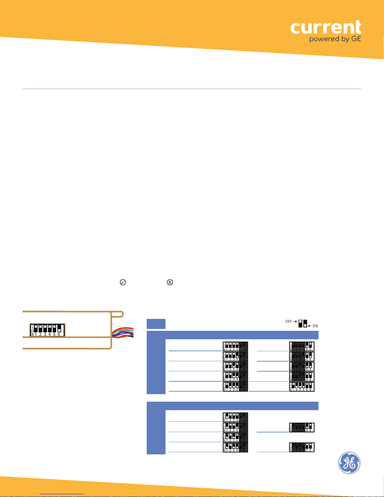
DIP switch settings
DIP switch settings enable the WA100-PM to operate appropriately for the type of lighting control it provides and the
type of device(s) to which it is connected and adapting for wireless communication. Set DIP switches based only on the
devices that are physically wired to the WA100-PM.
There are two primary adaptation modes to choose from as determined by the DIP switch 1 setting.
• In Light Adapter Mode, the settings are for the type
of lighting control that is available on the connected
driver, and/or the sensor type(s) connected to the
WA100-PM.
Configure DIP switch settings only as shown in this instruction. Incorrect switch settings will cause unexpected
operation.
• In the Switch Adapter Mode, settings are for the
connected switch type and whether the WA100-PM
is connected to a light.
After you change DIP switch settings, you need to press the blue Reset button for 3 seconds to reset the unit. Release
the button when the green Joined and red Error LEDs begin flashing.
Fig. 1: DIP switch location
Fig. 2: DIP Switch Table — See DIP switch Mode descriptions
for information about each option.
Mode
Light Adapter
Driver type switches 1 to 4
On/Off + 0-10V dimming
On/Off (no dimming)
Alternate Switching
Bi-Level
No Driver
(sensors only)
Switch type switches 1 to 4
Dimming
On/Off (no dimming)
Alternate Switch
Bi-Level
DIP Switch Positions:
Sensor switches 5 & 6
Occupancy
Photosensor
Both
None
Range Extender*
no light, no sensor
*Valid only with firmware v2.6 or higher
Light output ID
Light + Switch
(driver & switch
are same type)
No Light
(switch only)
5 & 6
2
Page 3

Wireless Adapter (WA100-PM)
Bi-Level Switching States
Alternate Switching States
DIP Switch Mode descriptions
Light Adapter Mode
Control Type
On/Off + 0-10V dimming: provides On/Off control using its line voltage Switched Load connection to the driver(s).
It also provides 0-10V dimming control to the driver(s).
On/Off (no dimming): provides On/Off control using its line voltage Switched Load connection, and its low voltage
digital output to an external relay. Note, both outputs are switched at the same time in this driver control mode.
Alternate: provides On/Off switching for one driver load using its line
voltage Switched Load connection, and its low voltage digital
output to an external relay to switch a second driver load. This allows
lighting level control for no load (0%), one or the other of the two loads,
and both loads (100%). See Figure 13.
Bi-Level: provides On/Off switching for one driver with two loads using its
line voltage Switched Load connection and low voltage digital output
an external relay to switch the second load. This allows lighting level
to control for no load (0%), partial load (according to driver capability)
Intensity Level WA100 Switched Aux Relay
Off (0%) Off Off
Low (1-49%) On Off
Medium (50-99%) Off On
Maximum (100%) On On
Intensity Level WA100 Switched Aux Relay
Off (0%) Off Off
Medium (1-99%) On Off
Maximum (100%) On On
or full load (100%). See Figure 12.
No Driver (sensors only): provides wireless adaptation to connected occupancy sensor and/or photosensor only.
No driver control.
Sensor
To provide wireless adaptation for sensors, set DIP switches 1, 5 & 6 according to the type(s) of sensors
connected to the WA100-PM.
Range Extender
The WA100-PM joins the ZigBee network and acts only as a wireless repeater to improve the wireless range
and/ or reliability. No lights or devices are connected to the WA100-PM.
Switch Adapter Mode
Switch Type
Dimming: operating the connected switch generates dimming and On/Off signals.
On/Off (no dimming): operating the connected switch generates On/Off signals.
Alternate: operating the connected switch will switch separate drivers, providing no load (0%), partial
load (one or the other of the two loads, according to the driver loading) or full load (100%).
Bi-Level: operating the connected switch will switch loads independently in a bi-level driver (or 2 drivers),
providing no load (0%), partial load (according to the driver capability or driver loading) or full load (100%).
3
Page 4

Wireless Adapter (WA100-PM)
Switch Adapter Mode continued
Light output ID
Light + Switch (driver and switch are the same type): the connected driver matches the operational capability
of the switch. For example:
• If the Switch type is “Dimming,” a dimming switch and 0-10V dimmable driver are both connected to the
WA100-PM. See Figure 10.
• If the Switch type is “On/Off (no dimming)” an On/Off switch is connected to the WA100-PM digital input
and On/Off driver(s) are connected to the WA100-PM’s line voltage Switched Load connection and/or an
external relay connected to the WA100-PM’s low voltage digital output.
• If the Switch type is “Bi-Level,” a bi-level driver and bi-level switch connect to the WA100-PM.
No Light (switch only): provides wireless adaptation for the selected switch type only. No light is connected to
the WA100-PM.
Occupancy Sensor Time Delays
Occupancy sensor time delays must be set for minimum.
When the ControlScope lighting control network is commissioned, time delays are set in the Daintree ControlScope
Manager (CSM) system. These CSM “Off delays” start counting down after the sensor’s internal time delay expires.
Therefore, set occupancy sensors for the minimum time delay during the WA100-PM installation.
Wiring
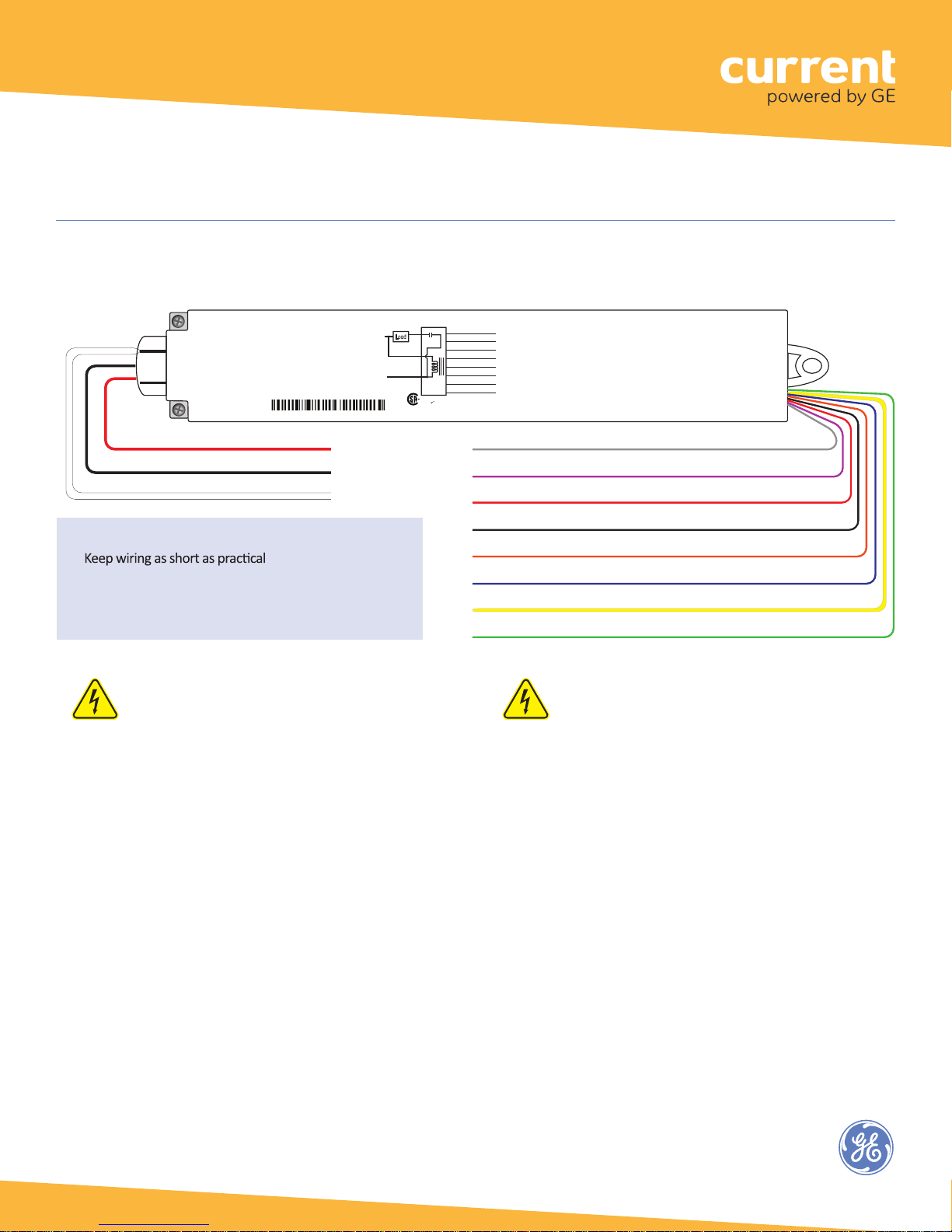
Line voltage wiring connects to the electrical supply circuit and to the driver(s). The Black (Hot) flying lead and the Red
(Switched Load) flying lead are 14AWG. The White (Neutral) flying lead is 18AWG.
Low voltage 22AWG flying leads provide for connections to supply low voltage power and carry control signals to and
from low voltage devices such as switches, dimmers, photocells, isolated relays and 0-10V analog dimming driver
controls. Do not connect any single low voltage device to more than one WA100-PM.
While the WA100-PM is in Installation Test mode the low voltage devices connected to the WA100-PM directly control
the lights wired to the same WA100-PM. After you exit Installation Test mode, the lights turn On and are NOT controlled
by the devices connected to the WA100-PM.
After joining the wireless network, the control signals from the low voltage devices pass through the WA100-PM and
are sent wirelessly to the ControlScope network. Depending on the zone and device configuration in the CSM, wireless
signals from the WAC to the WA100-PM determine the operation of the light(s).
Design Caution
Wireless adapters must always be provided with uninterrupted power. Do not install
a wireless adapter such as the WA100-PM to control an electrical circuit that provides
power to other wireless devices or adapters. If power to wireless adapters or devices
is shut off, control and communication with them is disabled.
4
Page 5
Wireless Adapter (WA100-PM)
Line Voltage
Low Voltage
Fig. 3: Wiring Identification
Blue (Digital In 1)
Wiring
Wireless Adapter with Power Monitoring
Model: WA100-PM
Input: 120-277VAC, 50/60 Hz
Load: 15A@120-277VAC Ballast or Incandescent, 1hp@120-230VAC
Output: +24VDC; 75mA
Ambient Temperature -4° to 149°F (-20° to 65°C)
FOR INDOOR USE ONLY UL 2043 Plenum Rated
Patent: www.daintree.net/company/patents
IEEE Address: 00228103007-00000
15A
Neut
Load
15A+45mA
Hot
45mA
White
Black
C
Red
Relay
WA100-PM
US
RoHS
Yellow (Digital In 2)
Orange (0-10V In)
Red (24VDC Output)
Black (Ground)
Green (Digital Out LSD)
Violet (0-10V Out)
Gray (Ground)
CONTAINS FCC ID: Z6G-DT357
CONTAINS IC: 10478A-DT357
CAN ICES-3 (B)/NMB-3(B)
Wiring
22AWG
RED 14AWG Switched Load 120-277VAC
BLACK 14AWG Hot 120-277VAC
WHITE 18AWG Neutral
Reducing noise on low voltage (0-10V) wiring
•
• Keep signal lines separate from mains voltage lines.
• Reduce the area created by the signal lines and the GND
return (i.e., keep them close together).
• If possible twist the signal line with the GND return.
GRAY Analog Ground
VIOLET 0-10V Analog output (dimming control)
RED 24VDC Power output
BLACK Digital Ground
ORANGE 0-10V Analog input (photosensor)
BLUE Digital input 1 (active high: occ. sensor -or- On/Dim Up for switch mode)
YELLOW Digital input 2 (active high: Off/Dim Down input for switch mode)
GREEN Digital output (On/Off for aux power pack, bi-level & alternate ballast control)
CAUTION: Risk of electrical shock
• Disconnect all power before installation and during servicing. Do not open WA100-PM
enclosure; no user-serviceable parts inside.
• All installation and maintenance of line voltage equipment must be performed by a
qualified electrician.
• The WA100-PM must be installed in accordance with all local, state, and national
electrical codes and requirements.
• Wiring connectors are not supplied. UL recognized wiring connectors must be used in
the installation.
5
Page 6
WHITE Neutral
Wireless Adapter (WA100-PM)
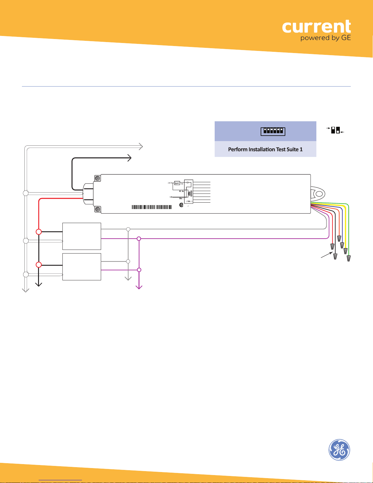
Fig. 4: Dimming Light Fixtures:
Line Voltage
Wires
RED Switched Load
120-277VAC
Hot
Neutral
Hot
Neutral
BLACK Hot 120-277VAC
Dimming Ballast
or LED Driver
(0-10VDC)
Dimming Ballast
or LED Driver
(0-10VDC)
Blue (Digital In 1)
15A
GRAY (-)
VIOLET (+)
GRAY (-)
VIOLET (+)
Wireless Adapter with Power Monitoring
Model: WA100-PM
Input: 120-277VAC, 50/60 Hz
Load: 15A@120-277VAC Ballast or Incandescent, 1hp@120-230VAC
Output: +24VDC; 75mA
Ambient Temperature -4° to 149°F (-20° to 65°C)
FOR INDOOR USE ONLY UL 2043 Plenum Rated
Patent: www.daintree.net/company/patents
IEEE Address: 00228103007-00000
GRAY Analog Ground
*
VIOLET 0-10V Analog Output (dimming control)
*
0-10V Dimming output
*
5 mA available
Up to 10 LED drivers or flourescent ballasts typical; the chance of low voltage errors increases with more.
Load
15A+45mA
Yellow (Digital In 2)
Relay
Orange (0-10V In)
45mA
Red (24VDC Output)
Black (Ground)
Green (Digital Out LSD)
Violet (0-10V Out)
Gray (Ground)
W
CONTAINS FCC ID: Z6G-DT357
CONTAINS IC: 10478A-DT357
RoHS
C
US
CAN ICES-3 (B)/NMB-3(B)
Driver type:
On/Off + 0-10V
dimming
DIP Switches
↓
DIP Switch Positions:
O
1 2 3 4 5 6
N
( all O F F)
Wired
Sensor:
None
Cap unused wires.
OFF
Low Voltage
Wires
ON
6
Page 7
( #4 O N )
DIP Switches
WHITE Neutral
Wireless Adapter (WA100-PM)
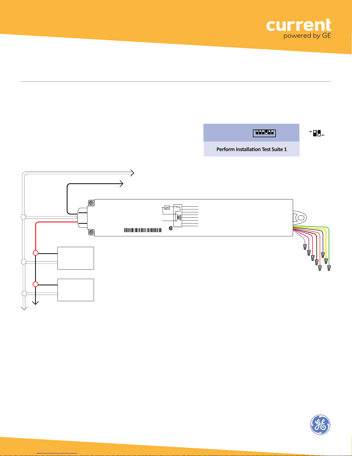
Fig. 5: On/Off (non-dimming) Light Fixtures:
This configuration allows the WA100-PM to provide automatic On/Off switching of light fixtures.
Line Voltage
Wires
RED Switched Load
120-277VAC
Hot
Neutral
Hot
Neutral
BLACK Hot 120-277VAC
ON/OFF
Light
Fixture
ON/OFF
Light
Fixture
Wireless Adapter with Power Monitoring
Model: WA100-PM
Input: 120-277VAC, 50/60 Hz
Load: 15A@120-277VAC Ballast or Incandescent, 1hp@120-230VAC
Output: +24VDC; 75mA
Ambient Temperature -4° to 149°F (-20° to 65°C)
FOR INDOOR USE ONLY UL 2043 Plenum Rated
Patent: www.daintree.net/company/patents
IEEE Address: 00228103007-00000
Neut
Hot
Load
15A+45mA
45mA
White
Black
C
15A
Red
WA100-PM
US
Relay
RoHS
Blue (Digital In 1)
Yellow (Digital In 2)
Orange (0-10V In)
Red (24VDC Output)
Black (Ground)
Green (Digital Out LSD)
Violet (0-10V Out)
Gray (Ground)
CONTAINS FCC ID: Z6G-DT357
CONTAINS IC: 10478A-DT357
CAN ICES-3 (B)/NMB-3(B)
Driver type:
On/Off (no dimming)
↓
O
DIP Switch Positions:
1 2 3 4 5 6
N
Wired
Sensor:
None
OFF
Low Voltage
Cap unused
ON
Wires
wires.
7
Page 8
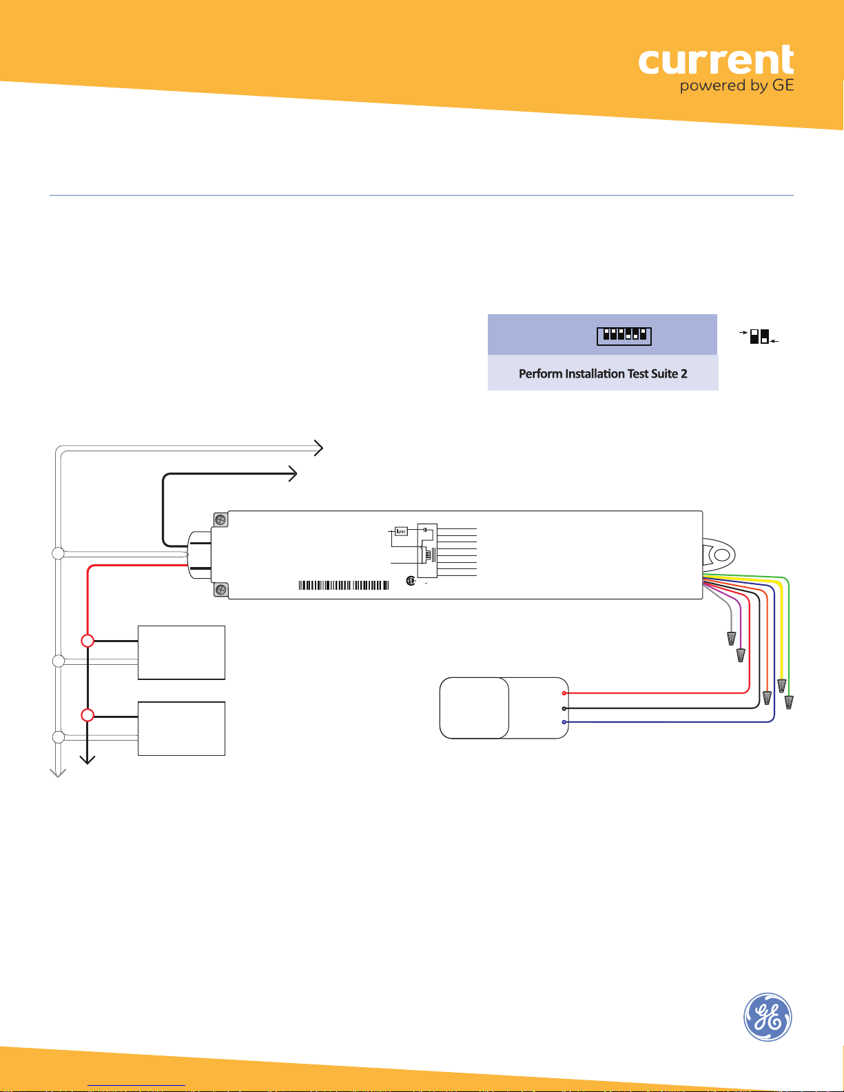
ON
( #4, 5 O N )
WHITE Neutral
Wireless Adapter (WA100-PM)
Fig. 6: On/Off (non-dimming) Light Fixture(s), Occupancy Sensor configuration:
This configuration allows the WA100-PM to provide automatic On/Off switching based on occupancy.
Set occupancy sensor for minimum time delay.
Line Voltage
Wires
RED Switched Load
120-277VAC
Hot
Neutral
Hot
Neutral
BLACK Hot 120-277VAC
ON/OFF
Light
Fixture
ON/OFF
Light
Fixture
Wireless Adapter with Power Monitoring
Model: WA100-PM
Input: 120-277VAC, 50/60 Hz
Load: 15A@120-277VAC Ballast or Incandescent, 1hp@120-230VAC
Output: +24VDC; 75mA
Ambient Temperature -4° to 149°F (-20° to 65°C)
FOR INDOOR USE ONLY UL 2043 Plenum Rated
Patent: www.daintree.net/company/patents
IEEE Address: 00228103007-00000
Neut
Hot
Load
15A+45mA
DIP Switches
Driver type:
On/Off (no dimming)
Blue (Digital In 1)
15A
Yellow (Digital In 2)
Red
Relay
Orange (0-10V In)
45mA
Red (24VDC Output)
White
Black (Ground)
Green (Digital Out LSD)
Violet (0-10V Out)
Black
Gray (Ground)
WA100-PM
CONTAINS FCC ID: Z6G-DT357
CONTAINS IC: 10478A-DT357
RoHS
C
US
CAN ICES-3 (B)/NMB-3(B)
24VDC
Occupancy
Sensor
24V in
Common
Control Out
↓
O
1 2 3 4 5 6
N
Wired
DIP Switch Positions:
Sensor:
Occupancy
RED 24VDC Power Output
BLACK Digital Ground
BLUE Digital Input 1
OFF
Low Voltage
Cap unused
Wires
wires.
8
Page 9
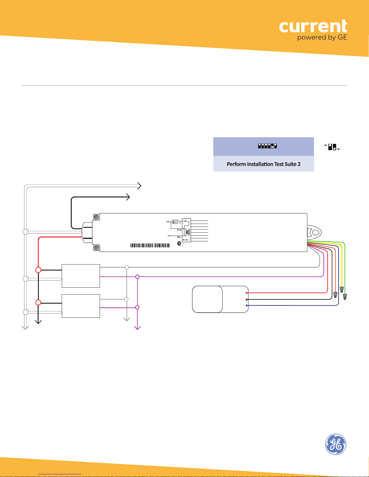
( #5 O N )
WHITE Neutral
Wireless Adapter (WA100-PM)
Fig. 7: Dimming Driver(s), Occupancy Sensor configuration:
This configuration allows the WA100-PM to provide automatic 0-10V dimming control and to switch drivers On/Off
based on occupancy. Set occupancy sensor for minimum time delay.
Line Voltage
Wires
RED Switched Load
120-277VAC
Hot
Neutral
Hot
Neutral
BLACK Hot 120-277VAC
Dimming Ballast
or LED Driver
(0-10VDC)
Dimming Ballast
or LED Driver
(0-10VDC)
GRAY (-)
VIOLET (+)
GRAY (-)
VIOLET (+)
DIP Switches
↓
O
DIP Switch Positions:
1 2 3 4 5 6
N
RED 24VDC Power Output
24VDC
Occupancy
Sensor
Driver type:
On/Off + 0-10V
dimming
24V in
Common
Control Out
Blue (Digital In 1)
15A
Wireless Adapter with Power Monitoring
Model: WA100-PM
Input: 120-277VAC, 50/60 Hz
Load: 15A@120-277VAC Ballast or Incandescent, 1hp@120-230VAC
Output: +24VDC; 75mA
Ambient Temperature -4° to 149°F (-20° to 65°C)
FOR INDOOR USE ONLY UL 2043 Plenum Rated
Patent: www.daintree.net/company/patents
IEEE Address: 00228103007-00000
GRAY Analog Ground
*
VIOLET 0-10V Analog Output (dimming control)
*
0-10V Dimming output
*
5 mA available
Up to 10 LED drivers or fluorescent ballasts typical; the chance of low voltage errors increases with more.
Load
15A+45mA
Yellow (Digital In 2)
Relay
Orange (0-10V In)
45mA
Red (24VDC Output)
Black (Ground)
Green (Digital Out LSD)
Violet (0-10V Out)
Gray (Ground)
CONTAINS FCC ID: Z6G-DT357
CONTAINS IC: 10478A-DT357
RoHS
C
US
CAN ICES-3 (B)/NMB-3(B)
Wired
Sensor:
Occupancy
OFF
BLACK Digital Ground
BLUE Digital Input 1
Low Voltage
Wires
Cap unused
wires.
ON
9
Page 10
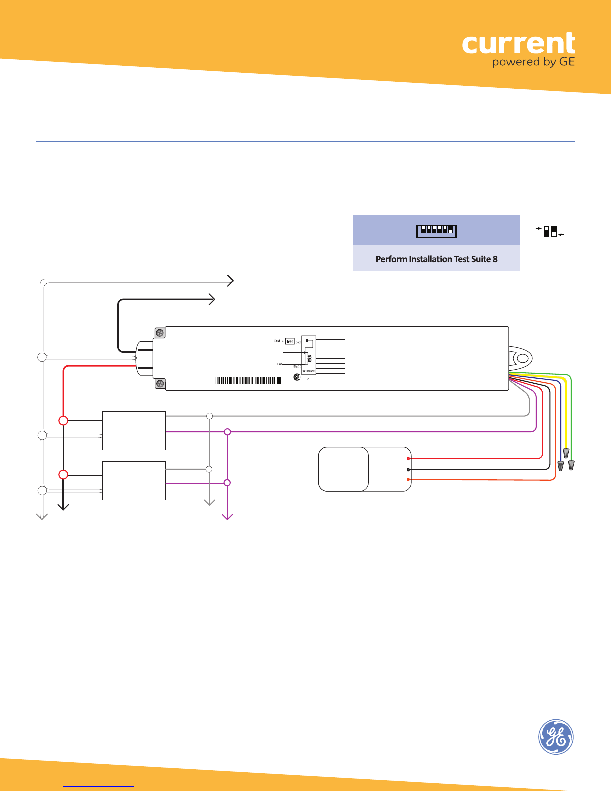
dimming
( #6 ON )
DIP Switches
WHITE Neutral
Up to 10 LED drivers or fluorescent ballasts typical; the chance of low voltage errors increases with more.
Wireless Adapter (WA100-PM)
Fig. 8: Dimming Light Fixture(s), Photosensor configuration:
This configuration allows the WA100-PM to provide automatic 0-10V dimming control and to switch light fixtures On/Off.
Line Voltage
Wires
RED Switched Load
120-277VAC
Hot
Neutral
Hot
Neutral
BLACK Hot 120-277VAC
Dimming Ballast
or LED Driver
(0-10VDC)
Dimming Ballast
or LED Driver
(0-10VDC)
GRAY (-)
VIOLET (+)
GRAY (-)
VIOLET (+)
15A
Load
15A+45mA
45mA
White
C
Relay
US
Wireless Adapter with Power Monitoring
Model: WA100-PM
Input: 120-277VAC, 50/60 Hz
Load: 15A@120-277VAC Ballast or Incandescent, 1hp@120-230VAC
Output: +24VDC; 75mA
Ambient Temperature -4° to 149°F (-20° to 65°C)
FOR INDOOR USE ONLY UL 2043 Plenum Rated
Patent: www.daintree.net/company/patents
IEEE Address: 00228103007-00000
GRAY Analog Ground
*
VIOLET 0-10V Analog Output (dimming control)
*
Blue (Digital In 1)
Yellow (Digital In 2)
Orange (0-10V In)
Red (24VDC Output)
Black (Ground)
Green (Digital Out LSD)
Violet (0-10V Out)
Gray (Ground)
CONTAINS FCC ID: Z6G-DT357
CONTAINS IC: 10478A-DT357
RoHS
CAN ICES-3 (B)/NMB-3(B)
24VDC
Photosensor
0-10V output
Driver:
On/Off + 0-10V
24V in
Common
0-10V Out
↓
O
1 2 3 4 5 6
N
Wired Sensor:
DIP Switch Positions:
Photosensor
OFF
RED 24VDC Power Output
BLACK Digital Ground
ORANGE 0-10V Analog Input
Low Voltage
Wires
Cap unused
wires.
ON
0-10V Dimming output
*
5 mA available
DT113 (Rev. 12.8.17)
10
Page 11
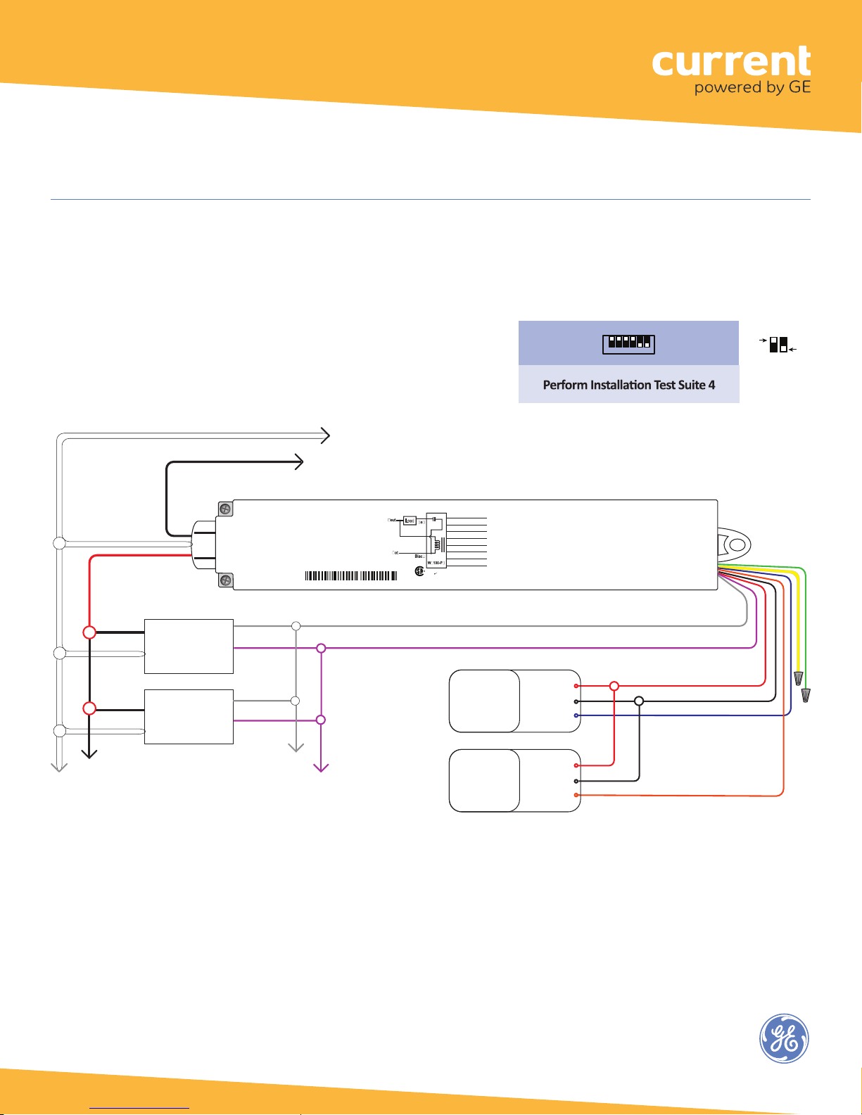
(#5, 6 ON )
WHITE Neutral
Wireless Adapter (WA100-PM)
Fig. 9: Dimming Light Fixture(s), Photosensor, Occupancy Sensor configuration:
This configuration allows the WA100-PM to provide automatic 0-10V dimming control and to switch drivers On/Off. Set
occupancy sensor for minimum time delay.
DIP Switches
BLACK Hot 120-277VAC
Driver:
On/Off + 0-10V
dimming
↓
O
1 2 3 4 5 6
N
Wired Sensor:
DIP Switch Positions:
Occupancy +
Photosensor
OFF
ON
Line Voltage
Wires
RED Switched Load
120-277VAC
Hot
Neutral
Hot
Neutral
Dimming Ballast
or LED Driver
(0-10VDC)
Dimming Ballast
or LED Driver
(0-10VDC)
*
5 mA available
Up to 10 LED drivers or fluorescent ballasts typical;
the chance of low voltage errors increases with more.
15A
Load
15A+45mA
Relay
45mA
White
RoHS
C
US
GRAY (-)
VIOLET (+)
Wireless Adapter with Power Monitoring
Model: WA100-PM
Input: 120-277VAC, 50/60 Hz
Load: 15A@120-277VAC Ballast or Incandescent, 1hp@120-230VAC
Output: +24VDC; 75mA
Ambient Temperature -4° to 149°F (-20° to 65°C)
FOR INDOOR USE ONLY UL 2043 Plenum Rated
Patent: www.daintree.net/company/patents
IEEE Address: 00228103007-00000
GRAY Analog Ground
*
VIOLET 0-10V Analog Output (dimming control)
*
GRAY (-)
VIOLET (+)
0-10V Dimming output
Blue (Digital In 1)
Yellow (Digital In 2)
Orange (0-10V In)
Red (24VDC Output)
Black (Ground)
Green (Digital Out LSD)
Violet (0-10V Out)
Gray (Ground)
CONTAINS FCC ID: Z6G-DT357
CONTAINS IC: 10478A-DT357
CAN ICES-3 (B)/NMB-3(B)
24VDC
Occupancy
Sensor
24VDC
Photosensor
0-10V output
24V in
Common
Control Out
24V in
Common
0-10V Out
RED 24VDC Power Output
BLACK Digital Ground
BLUE Digital Input 1
ORANGE 0-10V Analog Input
Low Voltage
Wires
Cap unused
wires.
11
Page 12
WHITE Neutral
Wireless Adapter (WA100-PM)
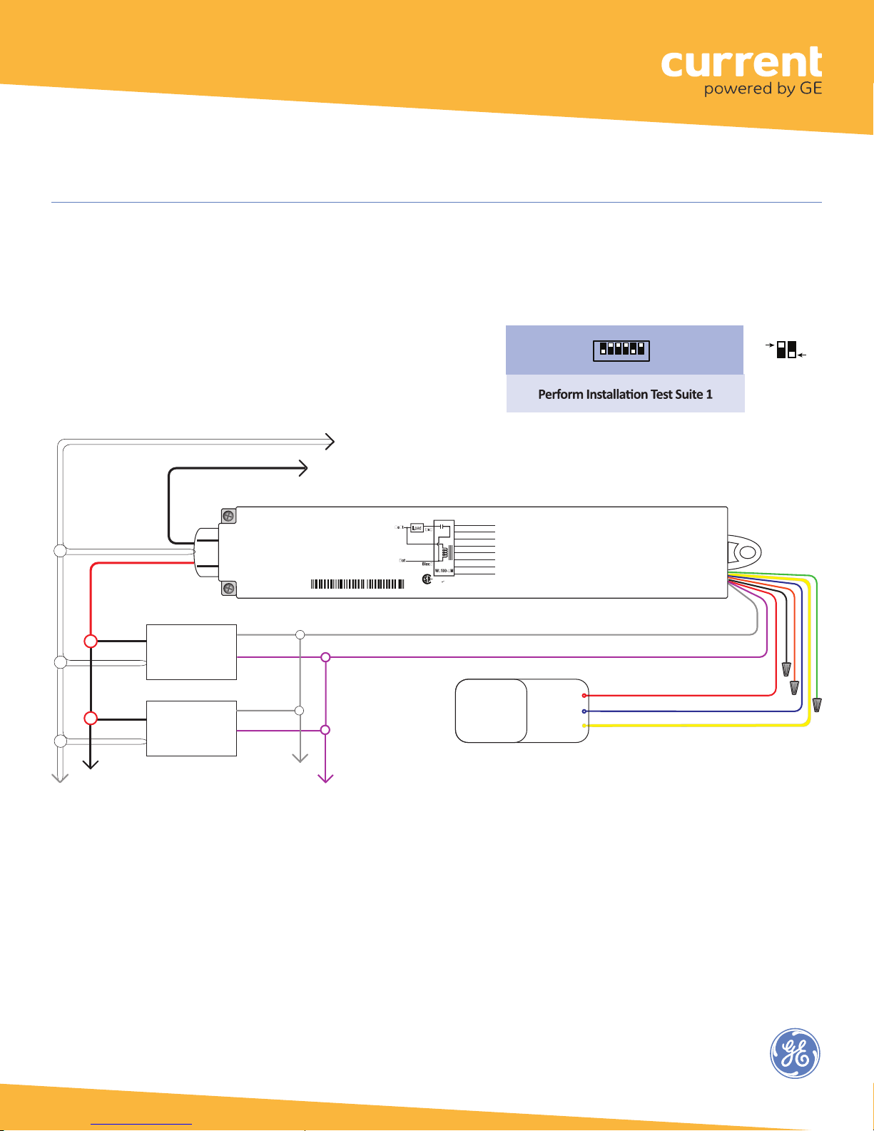
Fig. 10: Dimming Light Fixture(s) and Switch configuration:
This configuration allows the WA100-PM to provide 0-10V dimming control and to switch light fixtures On/Off. It also
provides manual On/Off control through a low voltage momentary contact switch.
Line Voltage
Wires
RED Switched Load
120-277VAC
Hot
Neutral
Hot
Neutral
BLACK Hot 120-277VAC
Dimming Ballast
or LED Driver
(0-10VDC)
Dimming Ballast
or LED Driver
(0-10VDC)
GRAY (-)
VIOLET (+)
GRAY (-)
VIOLET (+)
Wired
Switch Type:
Dimming
DIP Switches
↓
O
1 2 3 4 5 6
N
(# 1,5 ON)
Light output:
DIP Switch Positions:
driver same as
switch
Blue (Digital In 1)
15A
Wireless Adapter with Power Monitoring
Model: WA100-PM
Input: 120-277VAC, 50/60 Hz
Load: 15A@120-277VAC Ballast or Incandescent, 1hp@120-230VAC
Output: +24VDC; 75mA
Ambient Temperature -4° to 149°F (-20° to 65°C)
FOR INDOOR USE ONLY UL 2043 Plenum Rated
Patent: www.daintree.net/company/patents
IEEE Address: 00228103007-00000
GRAY Analog Ground
*
VIOLET 0-10V Analog Output (dimming control)
*
*
0-10V Dimming output
5 mA available
Up to 10 LED drivers or fluorescent ballasts typical; the chance of low voltage errors increases with more.
Load
15A+45mA
Yellow (Digital In 2)
Relay
Orange (0-10V In)
45mA
Red (24VDC Output)
White
Black (Ground)
Green (Digital Out LSD)
Violet (0-10V Out)
Gray (Ground)
CONTAINS FCC ID: Z6G-DT357
CONTAINS IC: 10478A-DT357
RoHS
C
US
CAN ICES-3 (B)/NMB-3(B)
Momentary
Contact
Switch
+24VDC
ON
OFF
RED 24VDC Power
OFF
BLUE Digital Input 1
YELLOW Digital Input 2
Low Voltage
Wires
Cap unused
wires.
ON
12
Page 13
Wireless Adapter (WA100-PM)
DIP Switches
WHITE Neutral
Bi-Level Switching States
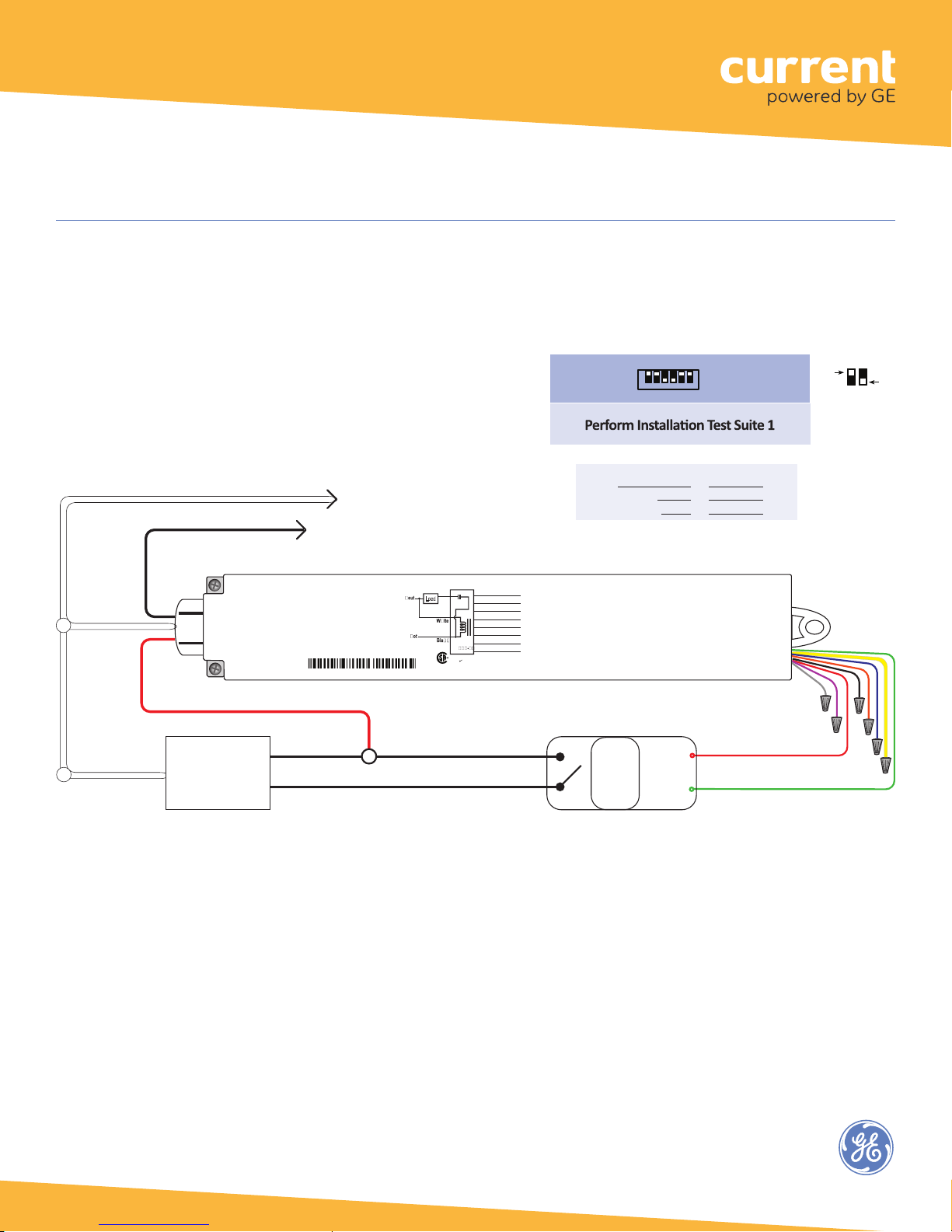
Fig. 11: Bi-level Switching:
This configuration allows the WA100-PM to switch loads independently in a bi-level driver (or 2 drivers), providing no
load (0%), partial load (according to the driver/ballast capability) or full load (100%).
Line Voltage
Wires
Neutral
BLACK Hot 120-277VAC
RED Switched Load 120-277VAC
Hot
Bi-Level
Driver/Ballast
(or 2 driver/ballasts)
Switched Hot
Wireless Adapter with Power Monitoring
Model: WA100-PM
Input: 120-277VAC, 50/60 Hz
Load: 15A@120-277VAC Ballast or Incandescent, 1hp@120-230VAC
Output: +24VDC; 75mA
Ambient Temperature -4° to 149°F (-20° to 65°C)
FOR INDOOR USE ONLY UL 2043 Plenum Rated
Patent: www.daintree.net/company/patents
IEEE Address: 00228103007-00000
Load
15A+45mA
45mA
C
15A
Red
Relay
WA
RoHS
US
Blue (Digital In 1)
Yellow (Digital In 2)
Orange (0-10V In)
Red (24VDC Output)
Black (Ground)
Green (Digital Out LSD)
Violet (0-10V Out)
Gray (Ground)
CONTAINS FCC ID: Z6G-DT357
CONTAINS IC: 10478A-DT357
CAN ICES-3 (B)/NMB-3(B)
Driver:
Bi-Level
↓
O
1 2 3 4 5 6
N
(# 3 ,4 ON )
DIP Switch Positions:
Intensity Level WA100 Switched Aux Relay
Off (0%) Off Off
Medium (1-99%) On Off
Maximum (100%) On On
RED 24VDC Power
GREEN Digital Ouptut LSD
Aux.
Relay
+24VDC
GND
Wired Sensor:
None
OFF
Low Voltage
Cap unused
Wires
wires.
ON
13
Page 14
Alternate Switching States
ON
DIP Switches
Wireless Adapter (WA100-PM)
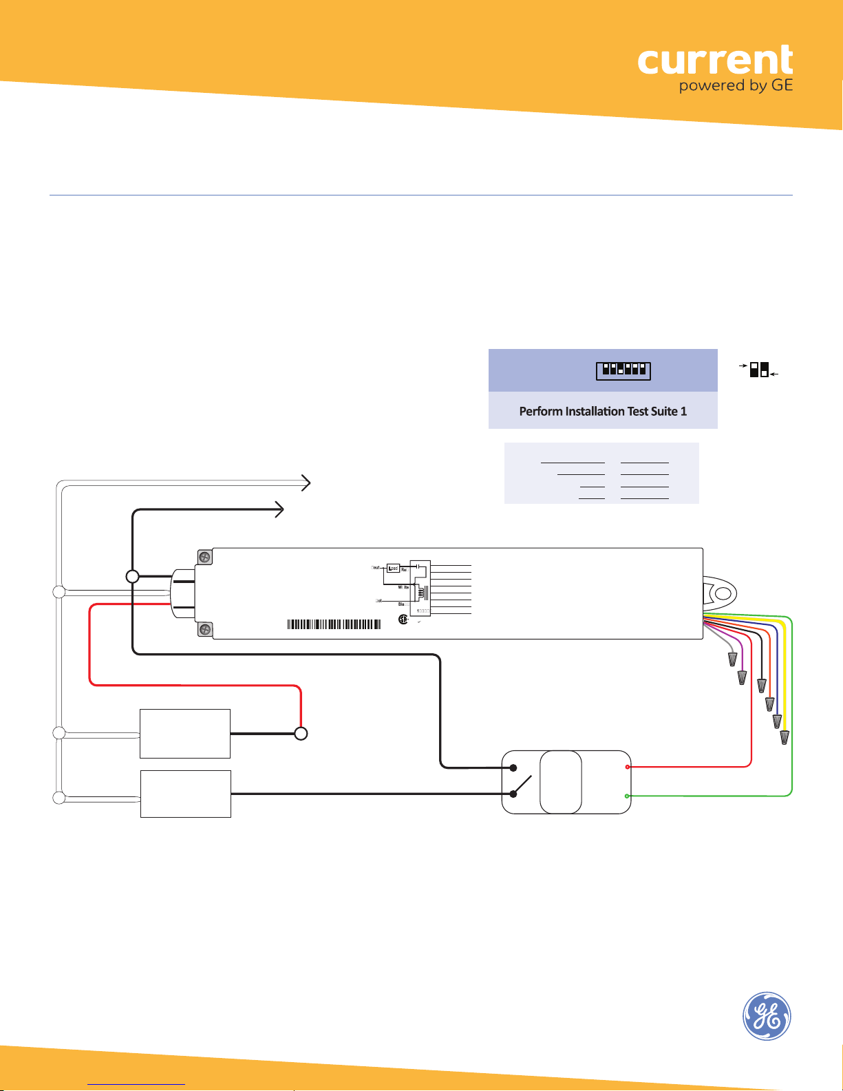
Fig. 12: Alternate Switching:
This configuration allows the WA100-PM to alternate in switching separate drivers, providing no load (0%), partial load
(according to the driver loading) or full load (100%).
Always connect the smaller proportion of the total load to the WA100-PM’s RED Switched Load wire.
Line Voltage
Wires
RED Switched Load 120-277VAC
Neutral
Neutral
Driver/Ballast 1
(1% to 49% of
Driver/Ballast 2
(50% to 99% of
WHITE Neutral
BLACK Hot 120-277VAC
Hot
total Load)
Hot
total Load)
Wireless Adapter with Power Monitoring
Model: WA100-PM
Input: 120-277VAC, 50/60 Hz
Load: 15A@120-277VAC Ballast or Incandescent, 1hp@120-230VAC
Output: +24VDC; 75mA
Ambient Temperature -4° to 149°F (-20° to 65°C)
FOR INDOOR USE ONLY UL 2043 Plenum Rated
Patent: www.daintree.net/company/patents
IEEE Address: 00228103007-00000
Load
15A+45mA
Driver:
Alternate Switching
↓
O
1 2 3 4 5 6
N
(# 3 ON)
Wired
DIP Switch Positions:
Sensor:
None
OFF
Intensity Level WA100 Switched Aux Relay
Off (0%) Off Off
Low (1-49%) On Off
Medium (50-99%) Off On
Maximum (100%) On On
Blue (Digital In 1)
15A
Yellow (Digital In 2)
Relay
Orange (0-10V In)
45mA
Red (24VDC Output)
Black (Ground)
Green (Digital Out LSD)
Violet (0-10V Out)
Gray (Ground)
WA
CONTAINS FCC ID: Z6G-DT357
CONTAINS IC: 10478A-DT357
RoHS
C
US
CAN ICES-3 (B)/NMB-3(B)
Hot
Aux.
Relay
+24VDC
GND
RED 24VDC Power
GREEN Digital Ouptut LSD
Low Voltage
Wires
Cap unused
wires.
14
Page 15
ON
( #4 O N )
DIP Switches
WHITE Neutral
Wireless Adapter (WA100-PM)
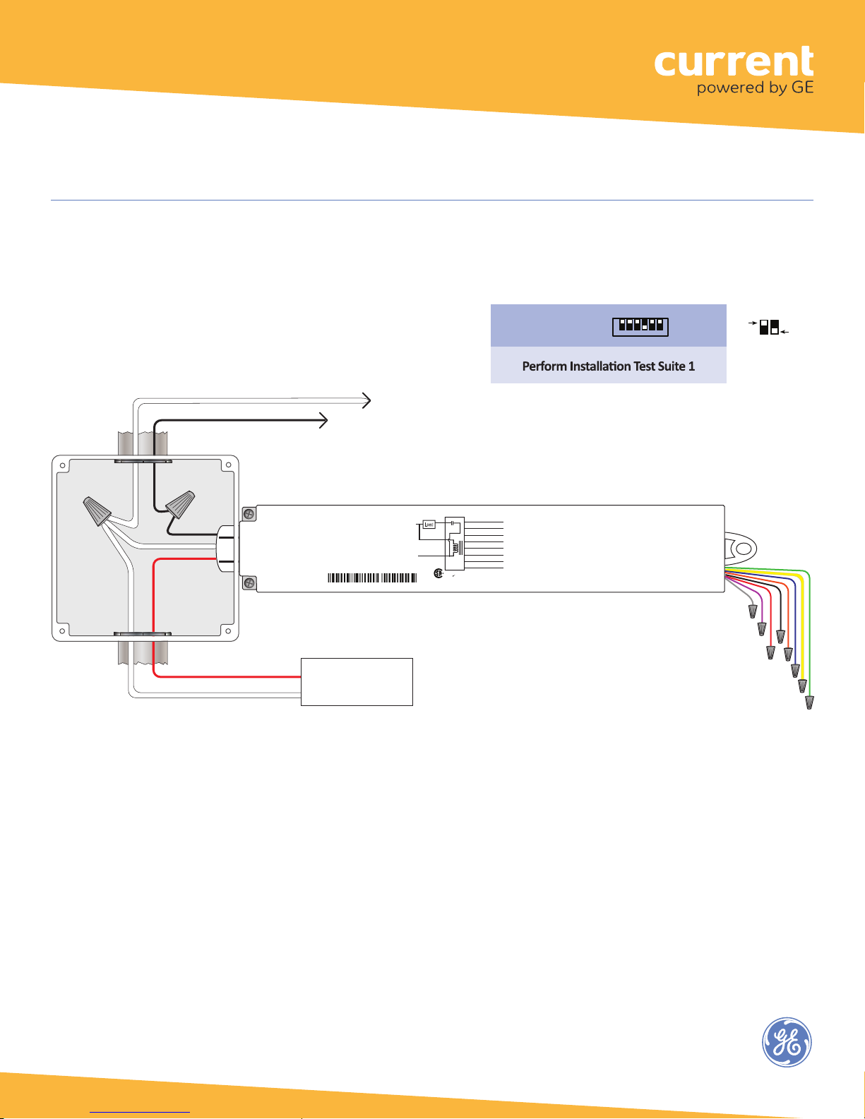
Fig. 13: Switching a Branch Circuit:
This configuration allows the WA100-PM to provide On/Off switching of a branch circuit.
Line Voltage
Wires
J-Box or
Equivalent
BLACK Hot 120-277VAC
RED
Switched Hot
Neutral
Wireless Adapter with Power Monitoring
Model: WA100-PM
Input: 120-277VAC, 50/60 Hz
Load: 15A@120-277VAC Ballast or Incandescent, 1hp@120-230VAC
Output: +24VDC; 75mA
Ambient Temperature -4° to 149°F (-20° to 65°C)
FOR INDOOR USE ONLY UL 2043 Plenum Rated
Patent: www.daintree.net/company/patents
IEEE Address: 00228103007-00000
Neut
Hot
Branch Circuit
Load
15A+45mA
45mA
White
C
Black
15A
Red
Relay
WA100-PM
US
Blue (Digital In 1)
Yellow (Digital In 2)
Orange (0-10V In)
Red (24VDC Output)
Black (Ground)
Green (Digital Out LSD)
Violet (0-10V Out)
Gray (Ground)
CONTAINS FCC ID: Z6G-DT357
CONTAINS IC: 10478A-DT357
RoHS
CAN ICES-3 (B)/NMB-3(B)
Driver type:
On/Off (no dimming)
↓
O
DIP Switch Positions:
1 2 3 4 5 6
N
Wired
Sensor:
None
OFF
Low Voltage
Wires
Cap unused
wires.
15
Page 16
( #4 O N )
DIP Switches
}
Wireless Adapter (WA100-PM)
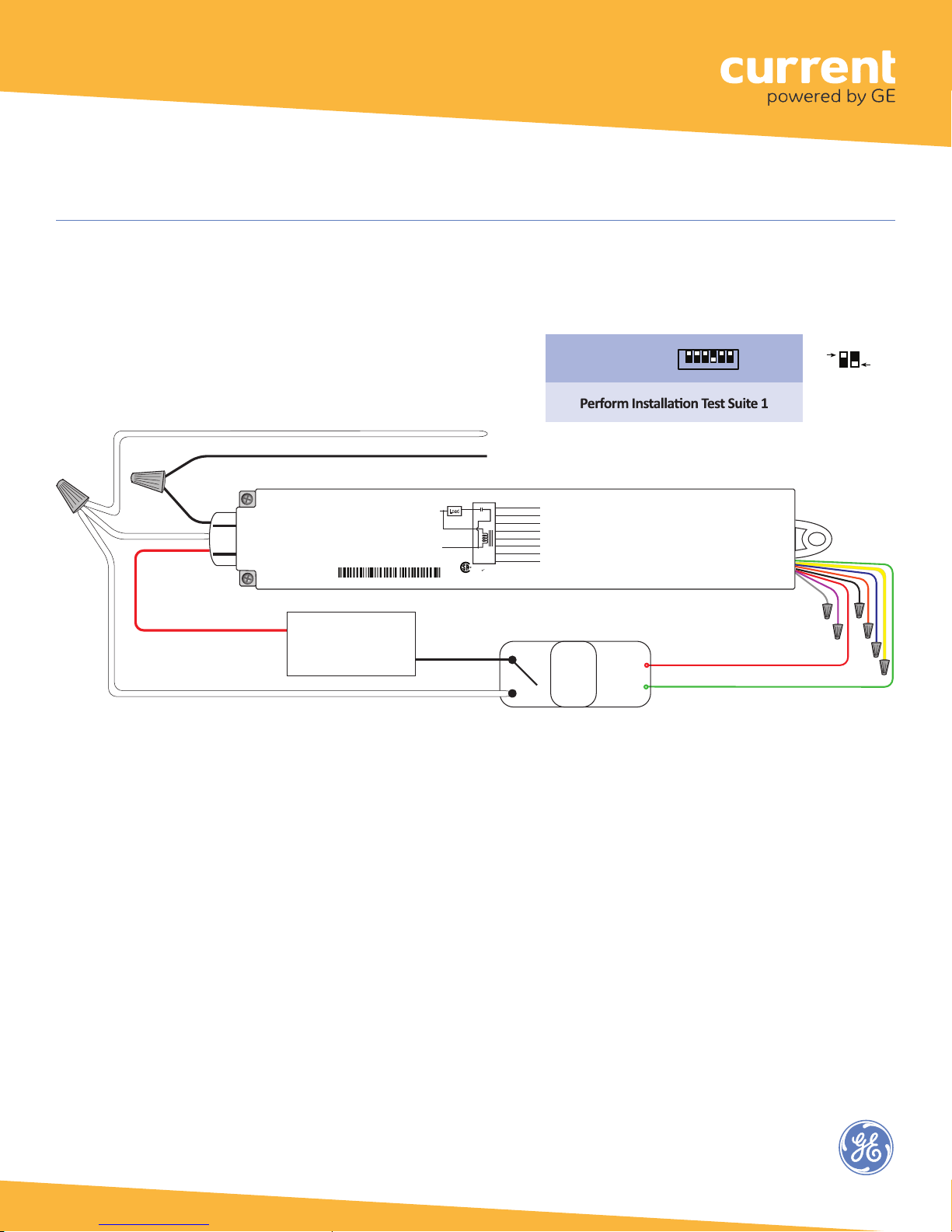
Fig. 14: 208V 2-Pole (Phase-to-Phase) wiring
This configuration allows the WA100-PM to provide On/Off switching of a branch circuit.
WHITE PHASE A (120V)*
Blue (Digital In 1)
15A
Yellow (Digital In 2)
Red
Relay
Orange (0-10V In)
45mA
Red (24VDC Output)
White
Black (Ground)
Green (Digital Out LSD)
Violet (0-10V Out)
Black
Gray (Ground)
WA100-PM
CONTAINS FCC ID: Z6G-DT357
CONTAINS IC: 10478A-DT357
RoHS
C
US
CAN ICES-3 (B)/NMB-3(B)
208V Supply
BLACK PHASE B (120V)*
Neut
Wireless Adapter with Power Monitoring
Model: WA100-PM
Input: 120-277VAC, 50/60 Hz
Load: 15A@120-277VAC Ballast or Incandescent, 1hp@120-230VAC
Output: +24VDC; 75mA
Ambient Temperature -4° to 149°F (-20° to 65°C)
FOR INDOOR USE ONLY UL 2043 Plenum Rated
Patent: www.daintree.net/company/patents
IEEE Address: 00228103007-00000
Load
15A+45mA
Hot
RED Switched Line Voltage*
Lighting Load
PHASE A*
PHASE A*
* Line Voltage Wires and connections must be secured in an appropriate enclosure,
in accordance with all local, state, and national electrical codes and requirements.
Wiring connectors are not supplied. UL recognized wiring connectors must be used in the installation.
Driver type:
On/Off (no dimming)
Aux.
+24VDC
Relay
GND
↓
O
DIP Switch Positions:
1 2 3 4 5 6
N
Wired
Sensor:
None
RED 24VDC Power
GREEN Digital Ouptut LSD
OFF
ON
Low Voltage
Wires
Cap unused
wires.
16
Page 17
( #4 O N )
DIP Switches
WHITE Neutral
Wireless Adapter (WA100-PM)
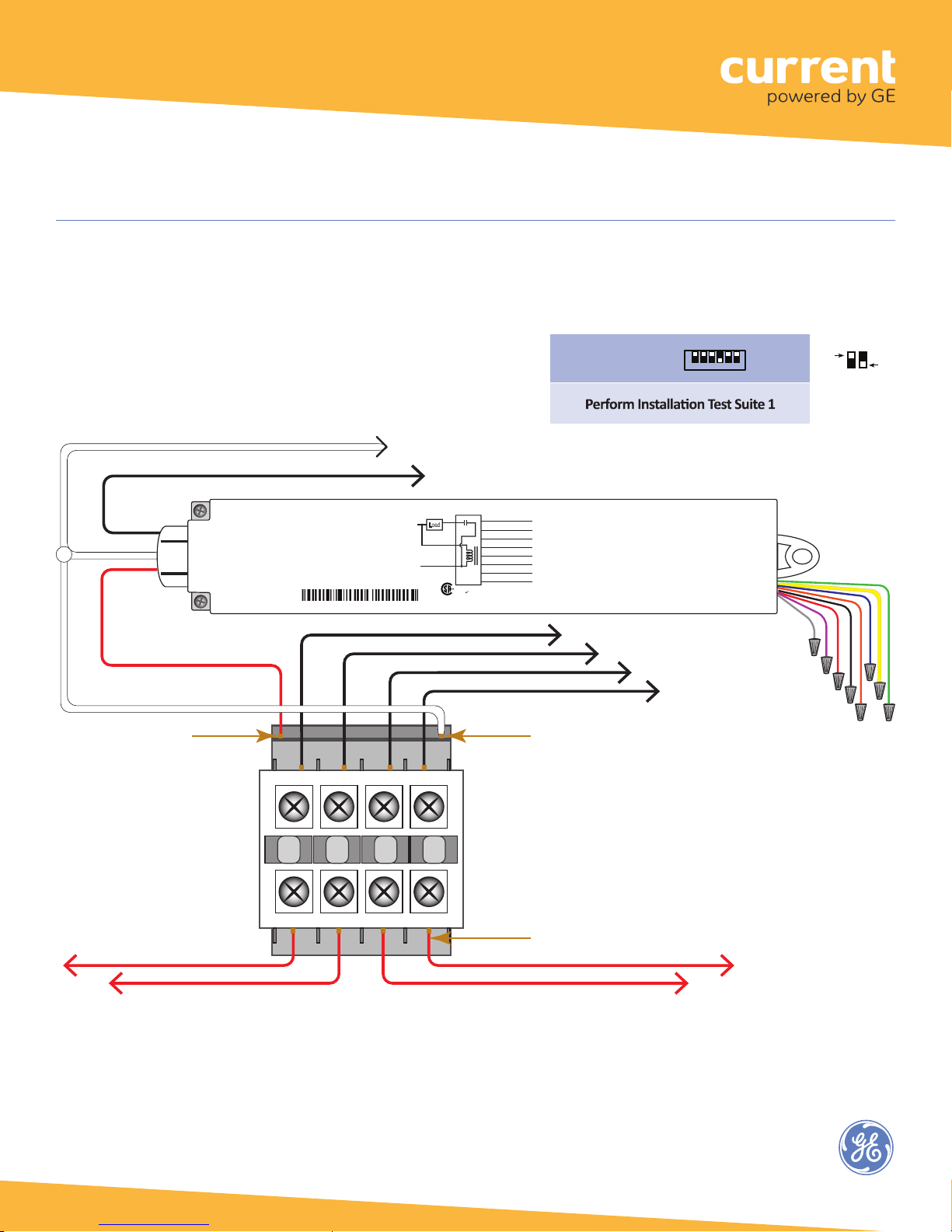
Fig. 15: Switching Contactors:
This configuration allows the WA100-PM to provide On/Off switching control to an external contactor.
Neutral
Line Voltage
Wires
RED
Switched Load
120/277VAC
Hot
Control Input
Hot
BLACK Hot 120/277VAC
Wireless Adapter with Power Monitoring
Model: WA100-PM
Input: 120-277VAC, 50/60 Hz
Load: 15A@120-277VAC Ballast or Incandescent, 1hp@120-230VAC
Output: +24VDC; 75mA
Ambient Temperature -4° to 149°F (-20° to 65°C)
FOR INDOOR USE ONLY UL 2043 Plenum Rated
Patent: www.daintree.net/company/patents
IEEE Address: 00228103007-00000
1L1 2 3L2 3 5L3 4 7L4
1
Neut
Hot
Load
15A+45mA
C
45mA
White
Black
15A
Red
Relay
WA100-PM
US
RoHS
Blue (Digital In 1)
Yellow (Digital In 2)
Orange (0-10V In)
Red (24VDC Output)
Black (Ground)
Green (Digital Out LSD)
Violet (0-10V Out)
Gray (Ground)
CONTAINS FCC ID: Z6G-DT357
CONTAINS IC: 10478A-DT357
CAN ICES-3 (B)/NMB-3(B)
Driver type:
On/Off (no dimming)
Control Input
Neutral
↓
O
DIP Switch Positions:
1 2 3 4 5 6
N
Line Voltage Supply
Hots
Wired
Sensor:
None
OFF
Low Voltage
Wires
Cap unused
wires.
ON
CONTACTOR
(120 or 277VAC
Coil Voltage)
1
2T1 2 4T2 3 6T3 4 8T4
Load Outputs
(Hot)
17
Page 18
Wireless Adapter (WA100-PM)
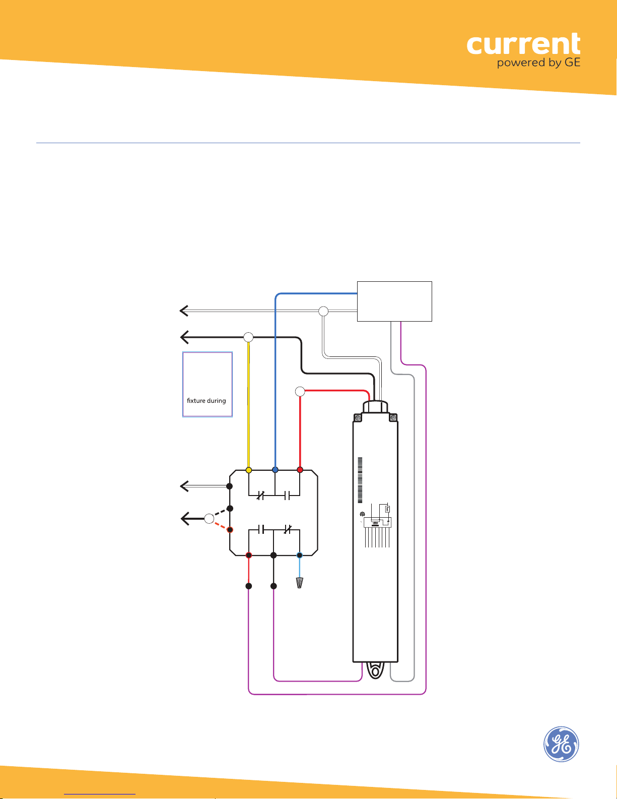
Fig. 16: Bypass WA100 switched power and 0-10V dimming control during power failure
In the wiring diagram here, while Regular power is supplied to the LVS model RRU-X-UM the WA100-PM provides
switched On/Off power and 0-10V dimming control to the fixture driver or ballast.
When the RRU-X-UM senses loss of Regular power it passes Emergency power directly to the fixture.
It disconnects the WA100-PM switched output and disconnects the WA100-PM dimming control so that the fixture will
operate at maximum output during the power failure.
EMERGENCY
Line Voltage (120-277VAC)
WHITE Neutral
Hot
Wiring to
bypass WA100
Line Voltage
and Dimming
control to
power failure
REGULAR
Line Voltage
(120-277VAC)
WHITE
YELLOW
NC
Neutral
Hot
LVS Model RRU-X-UM
*
NO
Connect
*
120VAC to BLK
277VAC to ORG
RED
BLUE
COM
COM
BLACK
WHITE Neutral
BLACK Hot
RED Switched Load
120-277VAC
RED
NO
NC
BLUE
FIXTURE
LED Driver or
Electronic Dimming
Ballast (0-10VDC)
GRAY
0-10V Ground
Wireless Adapter with Power Monitoring
Model: WA100-PM
Input: 120-277VAC, 50/60 Hz
Load: 15A@120-277VAC Ballast or Incandescent, 1hp@120-230VAC
Output: +24VDC; 75mA
Ambient Temperature -4° to 149°F (-20° to 65°C)
FOR INDOOR USE ONLY UL 2043 Plenum Rated
Patent: www.daintree.net/company/patents
IEEE Address: 00228103007-00000
Neut
Hot
Load
15A+45mA
C
45mA
White
Black
Red
US
WA100-PM
Relay
RoHS
CONTAINS FCC ID: Z6G-DT357
CONTAINS IC: 10478A-DT357
CAN ICES-3 (B)/NMB-3(B)
Green (Digital Out LSD)
Yellow (Digital In 2)
Orange (0-10V In)
Red (24VDC Output)
Black (Ground)
Violet (0-10V Out)
Gray (Ground)
WA100-PM
VIOLET
0-10V
dimming
Control
15A
Blue (Digital In 1)
VIOLET 0-10V
18
Page 19
EMERGENCY
Wireless Adapter (WA100-PM)
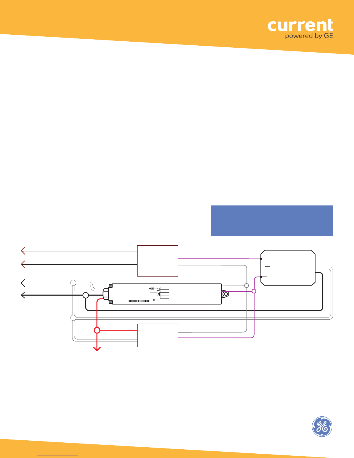
Fig. 17: Emergency and Regular Light Fixtures: Wiring to Dim while Regular Power is Available
In this application, the WA100-PM is powered by the Regular power circuit and is installed inside the Regular Light
Fixture. While Regular power is supplied to the RRU-2 the WA100-PM provides switched On/Off power to the Regular
Light Fixture.
The WA100-PM also controls dimming to the Regular and Emergency Light Fixture. The 0-10V dimming circuit from
the WA100-PM is brought into the Emergency Light Fixture. The Emergency Light Fixture is powered by the Emergency
power circuit.
When the RRU-2 senses loss of Regular power, the RRU-2 disconnects the 0-10V output from the WA100-PM and the
Emergency Light Fixture operates at maximum output from the Emergency power circuit. (Note: If the RRU-2 is not
installed, the Emergency Fixture will dim to minimum because the WA100-PM 0-10V output shorts when the adapter
loses power.)
Set DIP switches and perform Installation
Test appropriate to 0-10v dimming and
connected sensors.
Neutral
EMERGENCY
Hot 120-277VAC
REGULAR
Neutral
REGULAR
Hot 120-277VAC
Emergency Fixture
Dimming Ballast
or LED Driver
VIOLET 0-10V Analog Output
GRAY Analog Ground
(0-10VDC)
Blue (Digital In 1)
15A
Neut
Load
Yellow (Digital In 2)
Red
Relay
Orange (0-10V In)
45mA
Red (24VDC Output)
White
Black (Ground)
Green (Digital Out LSD)
15A+45mA
Hot
Violet (0-10V Out)
Black
Gray (Ground)
WA100-PM
CONTAINS FCC ID: Z6G-DT357
CONTAINS IC: 10478A-DT357
RoHS
C
US
CAN ICES-3 (B)/NMB-3(B)
or LED Driver
WA100-PM
RED Switched
Hot 120-277VAC
Wireless Adapter with Power Monitoring
Model: WA100-PM
Input: 120-277VAC, 50/60 Hz
Load: 15A@120-277VAC Ballast or Incandescent, 1hp@120-230VAC
Output: +24VDC; 75mA
Ambient Temperature -4° to 149°F (-20° to 65°C)
FOR INDOOR USE ONLY UL 2043 Plenum Rated
Patent: www.daintree.net/company/patents
IEEE Address: 00228103007-00000
Regular Fixture
Dimming Ballast
(0-10VDC)
Model RRU-2
N/O
GRAY
VIOLET
19
Page 20
Wireless Adapter (WA100-PM)
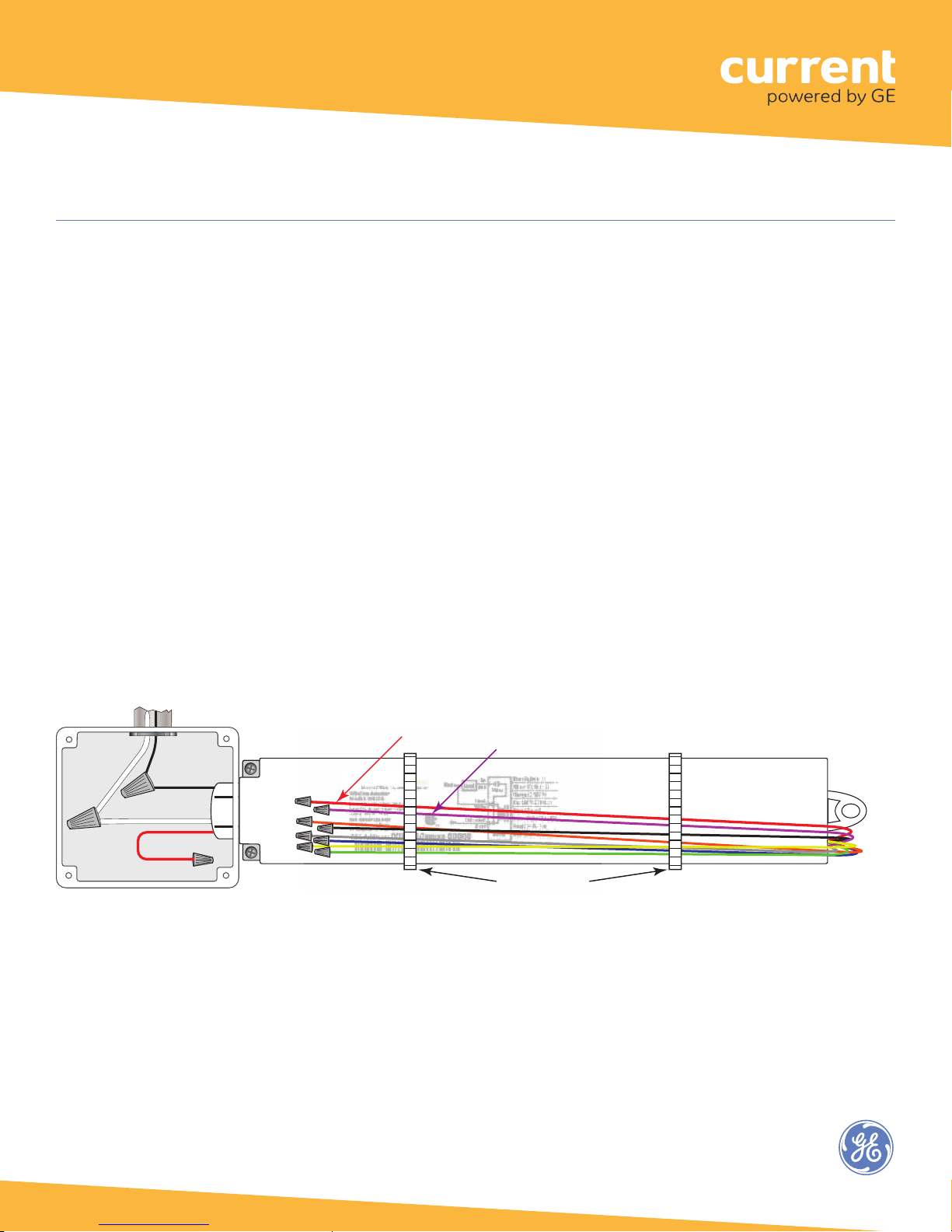
Trimming and Dressing
When the wiring connections have been decided and extra (unused) wires identified, secure the unused wires to keep
them neat, out of the way, and protected against shorting or interference with other components, wiring, or devices.
It is best to trim unused wires to about 5 inches in length, isolate them using a wire nut or equivalent, then bundle and
bind them close to the adapter’s body. Be sure that unused Red and Violet output wires are completely isolated from all
other wires. Unused line voltage wires must be securely isolated and housed inside a junction box, or other approved
electrical enclosure.
Securing Low Voltage Wires
1. Make sure the unit is NOT powered.
2. Cut the unused low voltage wires approximately five
inches from where they exit the WA100-PM body.
3. Isolate the end of each wire using a wire nut, shrink
tubing, or equivalent.
4. Wrap the unused low voltage wires around the side of
the adapter in a bunch, and secure them in place using a
white or clear cable tie.
Fig. 18: Secure unused wires
Line Voltage
Wires
J-Box or
Equivalent
Hot 120/230/277VAC
BLACK 14AWG
WHITE 18AWG Neutral
RED 14AWG
Switched load
Cap unused wires
RED: 24VDC power output
VIOLET: 0-10V output
Tie Wrap (or equiv.)
Low Voltage Wires
20
Page 21
Wireless Adapter (WA100-PM)
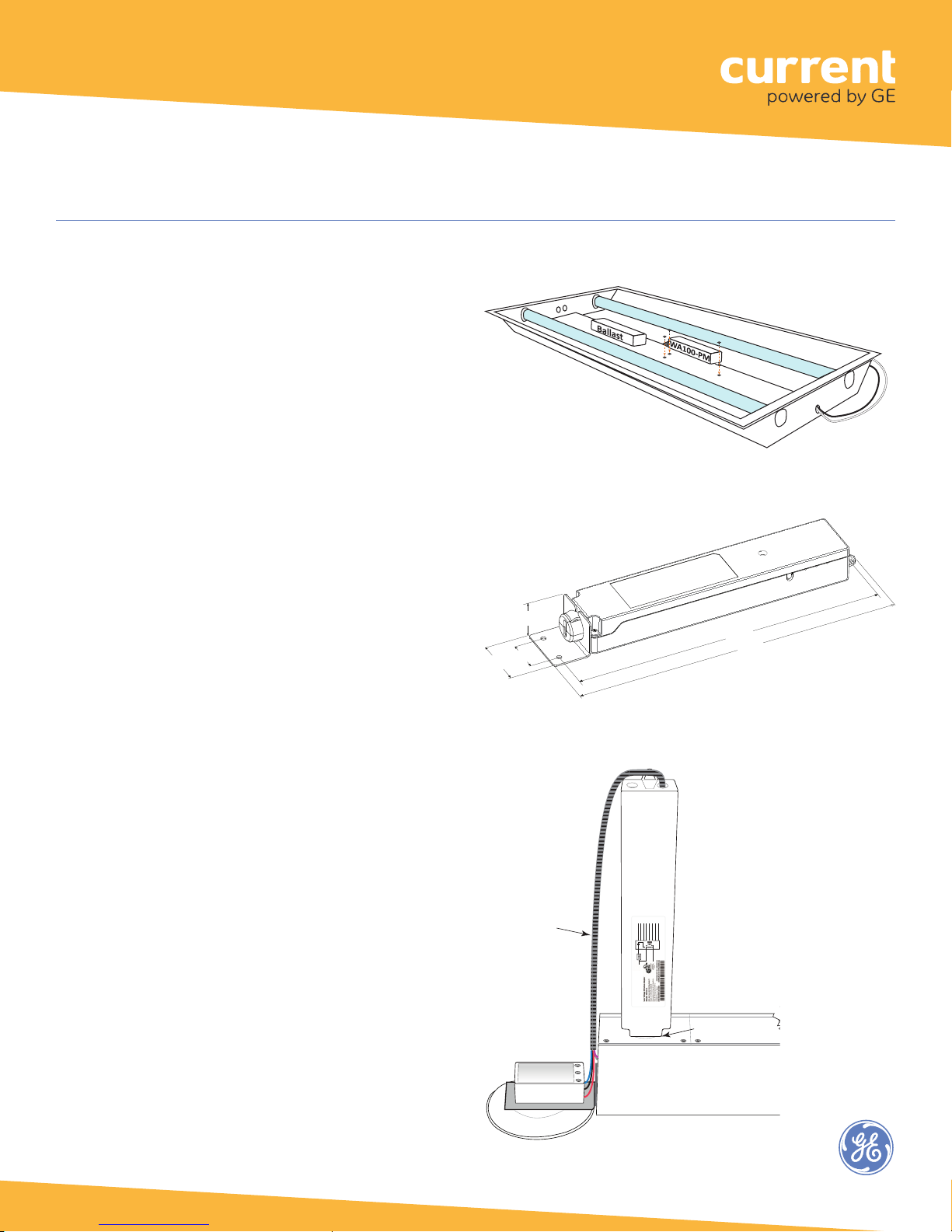
Mounting
The WA100-PM is designed so that it can be mounted in
a variety of ways. Depending on the construction of the
fixture and its ability to propagate radio signals, it can be
mounted inside the fixture in the ballast/driver channel.
A printed bar code label with the full IEEE address is
included with the WA100-PM. Affix this label to the outside
of the fixture. Choose a standard location so that when
someone looks for fixtures containing a WA100-PM,
they will easily find it.
Using the Mounting Bracket
The mounting bracket included with the WA100-PM
and shown in the illustration below provides a screw-
mounting alternative. The bracket has a slot that
allows wires to remain connected as you snap the
bracket onto the WA100-PM nipple. The WA100-PM
can be secured at the other end using the integral
screw tab.
Alternatively, it can be mounted externally to a
junction box, enclosure, or fixture housing through
a 1/2” knockout.
Fig. 19: Mounting in driver channel
Fig. 20: Mounting with the included bracket
1.18”
26
1.65”
(42 mm)
(30 mm)
1.02”
(26 mm)
9.53”
(242 mm)
10.08”
(256 mm)
Fig. 21: Mounting external to the top of a suspended fixture
Low Voltage
Wiring
(in sleeve)
Occupancy
Sensor
)
)
nalog In
(A
Blue (Digital In 1)
Yellow (Digital In 2)
Red (24VDC Output)
Black (Gnd
Violet (0-10V Out)
Orange
Green (Dig Out LSD)
Relay
WA100
C
e
12A
Red
45mA
Black
Whit
12A+45mA
Load
.
12A
Hot
US
Neut
C
A100
r, Model: W
te
12A Ballast or Incandescent Load
Output: 24VDC @75mAFOR INDOOR USE ONLY
UL 2043 Plenum Rated
Wireless Adap
Input: 120/230/277VAC, 50/60 Hz, 12A
WA100-PM
Grey (Gnd)
CONTAINS FCC ID: S4GEM35XA
CONTAINS IC ID: 8735A-EM35XA
Air Temperature -4 to 122°F (-20° to 50° C)
IEEE Address: 002281021002000A
Light Fixture
1/2” Knockout in
Fixture Housing (top)
21
Page 22

Wireless Adapter (WA100-PM)
Installation Tests
All lighting devices, including wireless adapters, must be tested for proper operation.
After setting the DIP switches for your application, mounting, wiring low voltage, wiring line voltage, powering up and
resetting the unit, perform the recommended Installation Test. The Installation Test mode automatically times out after
5 minutes of no activity.
While the WA100-PM is in Installation Test mode, the low voltage devices connected to the WA100-PM directly control
the lights wired to the same WA100-PM. After you exit the Installation Test mode, the lights turn On and are NOT
controlled by the devices connected to the WA100-PM. After commissioning the ControlScope system, lighting control is
determined by configuration settings in the ControlScope Manager.
IMPORTANT NOTICES
Complete Installation Tests
Successful commissioning is dependent on testing each wireless-adapted lighting fixture and/or control device
at the time of installation. Finding installation issues or device problems earlier saves significant time during the
commissioning process.
Record IEEE Addresses
If you have not already done so, be sure that each WA100-PM’s IEEE address (last 4 or 5 digits) is recorded on the
facility floor plan. You can use the 4 or 5 digit label supplied with the WA100-PM or you can write the last 4 or 5
digits on the floor plan. This information will be used during the commissioning process.
After the lighting installation is complete, a marked-up copy of the facility floor plan showing the identity and
location of each wireless adapter (including associated light fixtures, switches and sensors) should be available. This
will simplify and expedite the commissioning process.
Test Suite 1:
On/Off, Dimming, Alternate Switching or Bi-Level Drivers Only
1.
2. Check that the connected lights cycle On and Off, or cycle from maximum to minimum brightness then turn
Off per the DIP switch configuration.
3. Press and immediately release the Reset button to exit testing.
4. Press and hold the blue RESET button on the WA100-PM for 3 seconds to reset the unit. Release the button
when the green Joined LED and the red Error LEDs begin flashing.
Press and immediately release the blue Reset button. The red Error LED flashes once, then pauses and repeats.
22
Page 23

Wireless Adapter (WA100-PM)
Test Suite 2:
Any Driver + Occupancy Sensor
2. Check that the connected lights cycle On and Off, or cycle from maximum to minimum brightness then turn
Off per the DIP switch configuration.
3. Press and immediately release the blue Reset button again. The red Error LED flashes twice,
then pauses and repeats.
4. Trigger the occupancy sensor. The light connected to the driver turns On. When the sensor
times out the light turns Off.
5. Press and immediately release the Reset button to exit testing.
6. Press and hold the blue RESET button on the WA100-PM for 3 seconds to reset the unit. Release the button
when the green Joined LED and the red Error LEDs begin flashing.
Test Suite 3:
Dimming Driver + Occupancy Sensor + Photosensor
1.
2. Check that the lights connected to the driver cycle from maximum to minimum brightness then turn Off,
then repeat.
3.
4. Trigger the occupancy sensor. The green Joined LED turns On and the light connected to the driver turns On.
When the sensor times out the Joined LED and light turns Off.
5. Press and immediately release the blue Reset button again. The red Error LED flashes three times, then pauses
and repeats.
6. The light connected to the driver turns On.
7. The light’s output is proportional to the amount of light received by the photosensor.
•
Cover the photosensor –
• For switched lights, cover the photosensor – the light turns Off.
Shine a bright light at the photosensor – the light turns On.
8. Press and immediately release the Reset button to exit testing.
9. Press and hold the blue RESET button on the WA100-PM for 3 seconds to reset the unit. Release the button
when the green Joined LED and the red Error LEDs begin flashing.
1. Press and immediately release the blue Reset button. The red Error LED flashes once, then pauses and repeats.
Press and immediately release the blue Reset button. The red Error LED flashes once, then pauses and repeats.
Press and immediately release the blue Reset button. The red Error LED flashes twice, then pauses and repeats.
For dimming lights, shine a bright light at the photosensor – the light gets brighter.
the light gets dim.
23
Page 24

Wireless Adapter (WA100-PM)
Test Suite 4:
Any Switch(es) + Any Matching Light Type(s)
1.
2. Check that the connected lights cycle On and Off, or cycle from maximum to minimum brightness then turn
Off per the DIP switch configuration.
3. Press and immediately release the blue Reset button again. The red Error LED flashes four times, then pauses
and repeats.
4.
5. Press and immediately release the Reset button to exit testing.
6. Press and hold the blue RESET button on the WA100-PM for 3 seconds to reset the unit. Release the button
when the green Joined LED and the red Error LEDs begin flashing.
Test Suite 5:
Occupancy Sensor Only
1.
2. Trigger the occupancy sensor. The green Joined LED turns On. When the sensor times out the Joined LED
turns Off.
3. Press and immediately release the Reset button to exit testing.
4. Press and hold the blue RESET button on the WA100-PM for 3 seconds to reset the unit. Release the button
when the green Joined LED and the red Error LEDs begin flashing.
Press and immediately release the blue Reset button. The red Error LED flashes once, then pauses and repeats.
Operate the switch(es) connected to the WA100-PM and observe that the lights turn On, Off, and Dim as expected.
Press and immediately release the blue Reset button. The red Error LED flashes twice, then pauses and repeats.
Test Suite 6:
Photosensor Only
1. Press and immediately release the blue Reset button. The red Error LED flashes three times, then pauses
and repeats.
2. The green Joined LED begins to flash. Increase the amount of light at the photosensor by shining a bright light
at it. The green Joined LED flashes at a faster rate.
3. Press and immediately release the Reset button to exit testing.
4. Press and hold the blue RESET button on the WA100-PM for 3 seconds to reset the unit. Release the button
when the green Joined LED and the red Error LEDs begin flashing.
Test Suite 7:
Switch Only (On/Off, Dimming, Alternate Switching or Bi-Level)
1. Press and immediately release the blue Reset button. The red Error LED flashes four times, then pauses
and repeats.
2. Operate the switch connected to the WA100-PM. The green Joined LED turns On for the duration of the switch
activation (applies to On, Off, and Dim functions).
3. Press and immediately release the Reset button to exit testing.
4. Press and hold the blue RESET button on the WA100-PM for 3 seconds to reset the unit.
Release the button when the green Joined LED and the red Error LEDs begin flashing.
24
Page 25

Wireless Adapter (WA100-PM)
Test Suite 8:
Dimming Driver + Photosensor
1.
Press and immediately release the blue Reset button. The red Error LED flashes once, then pauses and repeats.
2. Check that the lights connected to the driver cycle from maximum to minimum brightness then turn Off,
then repeat.
3. Press and immediately release the blue Reset button again. The red Error LED flashes three times, then pauses
and repeats.
4. The light connected to the driver turns On.
5. Increase the amount of light at the photosensor by shining a bright light at it. The light’s output is proportional
to the amount of light received by the photosensor.
•
For dimming
Cover the photosensor – the light gets dim.
• For switched lights, cover the photosensor – the light turns Off.
Shine a bright light at the photosensor – the light turns On.
6. Press and immediately release the Reset button to exit testing.
7. Press and hold the blue RESET button on the WA100-PM for 3 seconds to reset the unit. Release the button
when the green Joined LED and the red Error LEDs begin flashing.
lights, shine a bright light at the photosensor – the light gets brighter.
Test Suite 9:
Occupancy Sensor + Photosensor
1.
Press and immediately release the blue Reset button. The red Error LED flashes twice, then pauses and repeats.
2. Trigger the occupancy sensor. The green Joined LED turns On. When the sensor times out the Joined LED
turns Off.
3. Press and immediately release the blue Reset button again. The red Error LED flashes three times, then pauses
and repeats.
4. The green Joined LED begins to flash. Increase the amount of light at the photosensor by shining a bright light
at it. The green Joined LED flashes at a faster rate.
5. Press and immediately release the Reset button to exit testing.
6. Press and hold the blue RESET button on the WA100-PM for 3 seconds to reset the unit. Release the button
when the green Joined LED and the red Error LEDs begin flashing.
25
Page 26

Wireless Adapter (WA100-PM)
Joining the ZigBee Lighting Control Network
After the Installation Test is complete the WA100-PM is ready to communicate with the Daintree Wireless Area Controller
(WAC) and the Daintree ControlScope Manager (CSM) web-based lighting management user interface. Upon commissioning,
the WA100-PM “Join” LED turns on solid and remains on as long as the WA100-PM is included in the ZigBee Network.
After joining the network, the low voltage devices connected to the WA100-PM do not directly control the lights that are
wired to the same WA100-PM. The control signals from the low voltage devices pass through the WA100-PM and are sent
wirelessly to the ControlScope network. Depending on the zone and device configuration in the CSM, wireless signals from
the WAC to the WA100-PM determine the operation of the light(s).
For more information about configuring the lighting control network, see the instructions and on-line help provided with the
ControlScope Manager application.
Troubleshooting
The Installation Test procedure fails.
1. Confirm that the WA100-PM is powered.
2. Check the connections from the WA100-PM to the driver(s) and low voltage control devices.
3. Check to be sure the WA100-PM DIP switch settings are correct.
4. Press and hold the Reset button for 3 seconds to reset the WA100-PM.
5. Perform the Installation Test again.
Connected lights do not turn Off during the occupancy sensor Installation Test.
1. Make sure the sensor is not detecting occupancy.
2. Check the occupancy sensor time delay and make sure it is set for minimum.
When the ControlScope lighting control network is commissioned, time delays are set in the Daintree
CSM system. These CSM “Off delays” start counting down after the sensor’s internal time delay expires.
Therefore, set occupancy sensors for the minimum time delay during the WA100-PM installation.
The red Error LED is flashing once every second.
DIP switch configuration is invalid. At least one DIP switch must be On to enable an interface.
1. Enable the interface(s) that are connected by turning appropriate DIP switch(es) On.
2. Press the blue Reset button for 3 seconds to reset the unit.
26
Page 27

Wireless Adapter (WA100-PM)
FCC warning message
This equipment has been tested and found to comply
with the limits for a Class B digital device, pursuant to
Part 15 of the FCC Rules. These limits are designed
to provide reasonable protection against harmful
interference in a residential installation. This equipment
generates, uses and radiates radio frequency energy
and, if not installed and used in accordance with the
instructions, may cause harmful interference to radio
communications. However, there is no guarantee that
interference will not occur in a particular installation.
If this equipment does cause harmful interference to
radio or television reception, which can be determined
by turning the equipment off and on, the user is
encourage to try to correct the interference by one
or more of the following measures:
• Reorient or relocate the receiving antenna;
• Increase the separation between the equipment
and receiver;
• Connect the equipment into an outlet on a
circuit different from that to which the receiver
is connected;
• Consult the dealer or an experienced radio/TV
technician for help.
Industry Canada (IC) Warning
Message
Product complies with Part 15 of the FCC Rules.
Operation is subject to the following two conditions: (1)
This device may not cause harmful interference, and (2)
This device must accept any interference received,
including interference that may cause undesired
operation. CAN ICES-005 B / NMB-005 B
Input Voltage
Switched Output Relay
Low Voltage Output
Low Voltage Wiring
Specifications
Memory and Storage
Analog Dimming
Analog Input
Digital Inputs (2)
Digital Output
Radio Properties
Operating Environment
Compliance
Mounting
Dimensions
* “Driver” references include “ballasts” unless otherwise noted.
120-277VAC, 50-60Hz
15A driver/incandescent @ 120-277VAC
1hp @ 120-230VAC
(switched to Hot/Active)
24VDC; 75mA maximum
®
Intel
Atom™ Processor E3805
22AWG, 600V, UL 1015, plenum rated Max.
recommended length of up to 100’ (30m)
0-10VDC, 5mA max (sink or source), up to
10 typical 0.5mA sinking drivers/ballasts*
Photosensor 0-10VDC
Active high. Occupancy sensor,
Dim Up/Down (switch mode)
LSD (low side driver) aux relay control,
75mA maximum (including attached
sensors)
2.4 GHz, +8 dBm, Range dependent
on RF propagation variables such as
metal obstacles
Indoor, dry location
-4o to 149oF (-20o to 65oC)
CSA certified, plenum rated, FCC Part 15, CA IC
½” knockout, screw tab, optional mounting bracket supplied
9.4” L x 1.7” W x 1.18” H
10.1” L x 1.7” W x 1.18” H with
mounting bracket
Call 1 888 694 3533 products.currentbyge.com
GE is a trademark of the General Electric Company. All other trademarks are the property of their respective owners.
Information provided is subject to change without notice. All values are design or typical values when measured
under laboratory conditions. Current and GE Lighting are businesses of the General Electric Company. © 2017 GE
27
Page 28
Plug Load Applications (WA100-PM)
WHITE Neutral
WHITE Neutral
ON
(# 2,4 ON)
DIP Switches
ON
(# 2,3 ON)
DIP Switches
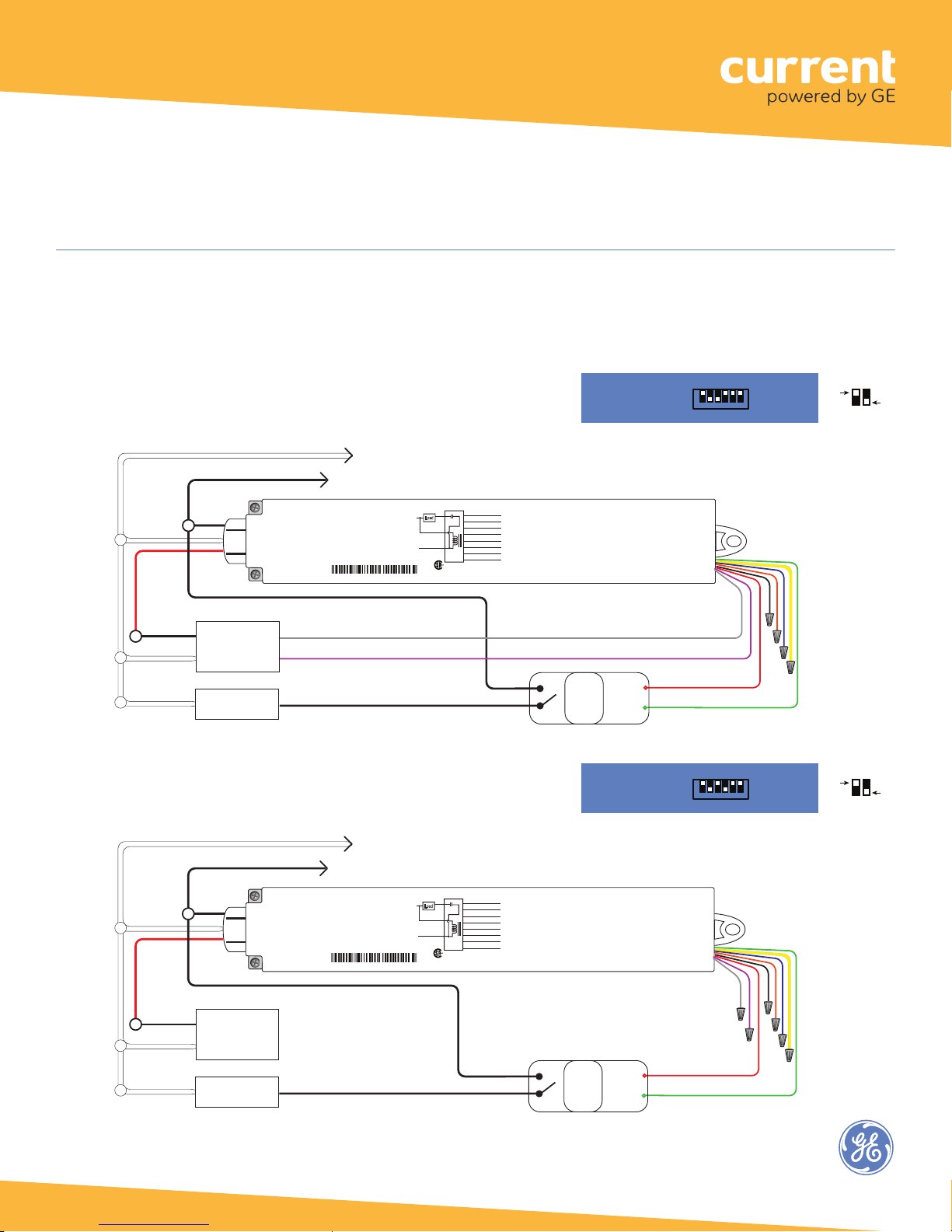
ii. Appendix 1: Installation Advisory - Plug Load Applications (WA100-PM)
Plug load control functionality for the WA100-PM is made available with WA100-PM firmware provided in ControlScope
Manager version 3.5.3.1. During testing the Plug Load cycles on/off in sync with the lighting load. Relays used to control
plug loads must be compliant with UL498 (Attachment Plug and Receptacles) or equivalent.
Wiring for Combination Plug Load (Basic Aux Relay) and Dimming Light
In the wiring diagram below, the WA100-PM is used to control both a
dimming light and a plug load circuit.
BLACK Hot 120-277VAC
Line Voltage
Wires
RED
Switched
Load
120-277VAC
Hot
Neutral
Dimming Ballast
or LED Driver
(0-10VDC)
www.daintree.net
Wireless Adapter with Power Monitoring
Model: WA100-PM
Input: 120-277VAC, 50/60 Hz
Load: 15A@120-277VAC Ballast or Incandescent, 1hp@120-230VAC
Output: +24VDC; 75mA
Ambient Temperature -4° to 149°F (-20° to 65°C)
FOR INDOOR USE ONLY UL 2043 Plenum Rated
Patent: www.daintree.net/company/patents
IEEE Address: 00228103007-00000
Neut
Hot
GRAY (-) Analog Ground
VIOLET (+) 0-10V Analog Output (dimming control)
Load
15A+45mA
Blue (Digital In 1)
15A
Yellow (Digital In 2)
Red
Relay
Orange (0-10V In)
45mA
Red (24VDC Output)
White
Black (Ground)
Green (Digital Out LSD)
Violet (0-10V Out)
Black
Gray (Ground)
WA100-PM
CONTAINS FCC ID: Z6G-DT357
CONTAINS IC: 10478A-DT357
RoHS
C
US
CAN ICES-3 (B)/NMB-3(B)
*
Hot
Neutral
Plug Load
Hot
Wiring for Combination Plug Load (Basic Aux Relay) and On/Off Light
In the wiring diagram below, the WA100-PM is used to control both an
On/Off light and a plug load circuit.
Driver: On/Off +
0-10V dimming
Plug Load: On/Off
DIP Switch Positions:
O
1 2 3 4 5 6
N
Perform Installation Test Suite 1
Low Voltage
**
GND
RED 24VDC Power
GREEN Digital Ouptut LSD
DIP Switch Positions:
O
1 2 3 4 5 6
N
+24VDC
Aux.
Relay
(20A)
Driver: On/Off
Plug Load: On/Off
Perform Installation Test Suite 1
Wired
Sensor:
None
Wires
Cap unused
wires.
Wired
Sensor:
None
OFF
OFF
BLACK Hot 120-277VAC
Line Voltage
Wires
RED
Switched
Load
120-277VAC
Hot
Neutral
Neutral
*0-10V Dimming output, 5 mA available, Up to 10 LED drivers or fluorescent
ballasts typical; the chance of noise on the signal increases with more.
**Relays used to control plug loads must be compliant with UL498
(Attachment Plug and Receptacles) or equivalant.
Ballast
or LED Driver
(non-dimming)
Plug Load
Hot
www.daintree.net
Wireless Adapter with Power Monitoring
Model: WA100-PM
Input: 120-277VAC, 50/60 Hz
Load: 15A@120-277VAC Ballast or Incandescent, 1hp@120-230VAC
Output: +24VDC; 75mA
Ambient Temperature -4° to 149°F (-20° to 65°C)
FOR INDOOR USE ONLY UL 2043 Plenum Rated
Patent: www.daintree.net/company/patents
IEEE Address: 00228103007-00000
Neut
Hot
Load
15A+45mA
Blue (Digital In 1)
15A
Yellow (Digital In 2)
Red
Relay
Orange (0-10V In)
45mA
Red (24VDC Output)
White
Black (Ground)
Green (Digital Out LSD)
Violet (0-10V Out)
Black
Gray (Ground)
WA100-PM
CONTAINS FCC ID: Z6G-DT357
CONTAINS IC: 10478A-DT357
RoHS
C
US
CAN ICES-3 (B)/NMB-3(B)
Hot
Aux.
Relay
(20A)
+24VDC
GND
**
RED 24VDC Power
GREEN Digital Ouptut LSD
Low Voltage
Wires
Cap unused
wires.
1
Page 29
Plug Load Applications (WA100-PM)
WHITE Neutral
Ground
ON
(# 2,3 ON)
DIP Switches
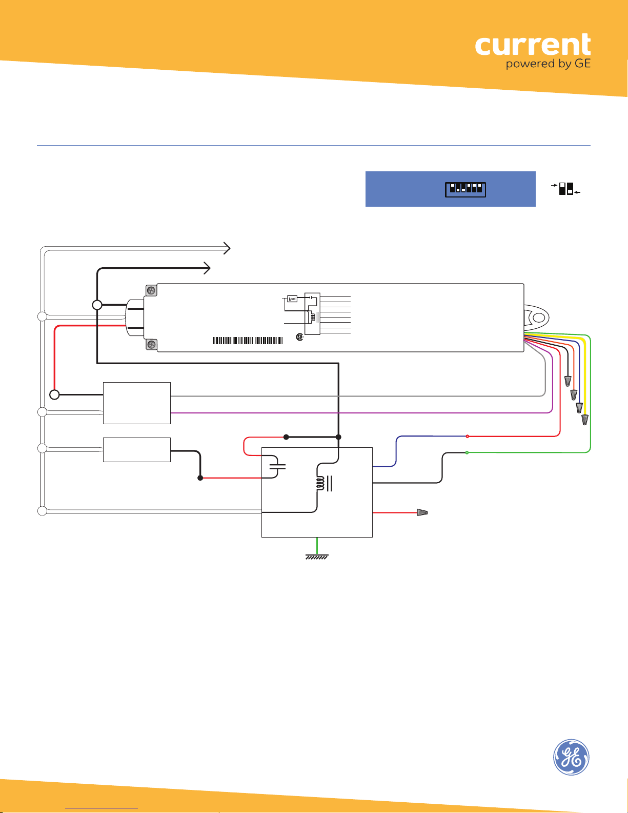
Wiring for Combination Plug Load (Aux Relay with
Input Control Signal) and Dimming Light
In the wiring diagram below, the WA100-PM is used to
control both a dimming light and a plug load circuit.
BLACK Hot 120-277VAC
Line Voltage
Wires
RED
Switched
Load
120-277VAC
Hot
Neutral
Neutral
Dimming Ballast
or LED Driver
(0-10VDC)
Plug Load
GRAY (-) Analog Ground
VIOLET (+) 0-10V Analog Output (dimming control)
SW Hot
www.daintree.net
Wireless Adapter with Power Monitoring
Model: WA100-PM
Input: 120-277VAC, 50/60 Hz
Load: 15A@120-277VAC Ballast or Incandescent, 1hp@120-230VAC
Output: +24VDC; 75mA
Ambient Temperature -4° to 149°F (-20° to 65°C)
FOR INDOOR USE ONLY UL 2043 Plenum Rated
Patent: www.daintree.net/company/patents
IEEE Address: 00228103007-00000
RED
RED
Driver: On/Off +
0-10V dimming
Plug Load: On/Off
O
1 2 3 4 5 6
N
Wired
DIP Switch Positions:
Sensor:
None
OFF
Perform Installation Test Suite 1
Load
15A+45mA
Hot
C
45mA
White
Black
Red
WA100-PM
US
Relay
RoHS
Yellow (Digital In 2)
Orange (0-10V In)
Red (24VDC Output)
Black (Ground)
Green (Digital Out LSD)
Violet (0-10V Out)
Gray (Ground)
CONTAINS FCC ID: Z6G-DT357
CONTAINS IC: 10478A-DT357
CAN ICES-3 (B)/NMB-3(B)
Blue (Digital In 1)
15A
Neut
Hot
Low Voltage
Wires
Cap unused
wires.
*
Hot
**
Control Output
BLUE
BLACK Common
RED 24VDC Power
GREEN Digital Ouptut LSD
Aux Relay with input
control signal (20A)
GREEN
RED 24VDC
*0-10V Dimming output, 5 mA available, Up to
10 LED drivers or fluorescent ballasts typical; the
chance of noise on the signal increases with more.
**Relays used to control plug loads must be
compliant with UL498 (Attachment Plug and
Receptacles) or equivalant.
2
Page 30
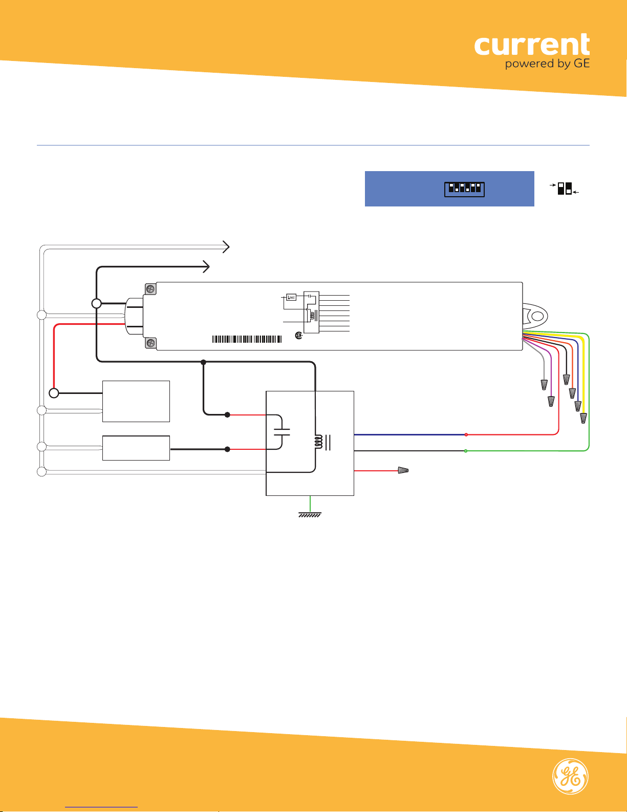
Plug Load Applications (WA100-PM)
ON
(# 2,4 ON)
DIP Switches
WHITE Neutral
Ground
Wiring for Combination Plug Load (Aux Relay with Input
Control Signal) and On/Off Light
In the wiring diagram below, the WA100-PM is used to
control both an On/Off light and a plug load circuit.
BLACK Hot 120-277VAC
Line Voltage
Wires
RED
Switched
Load
120-277VAC
Hot
Neutral
Neutral
Ballast
or LED Driver
(non-dimming)
Plug Load
SW Hot
www.daintree.net
Wireless Adapter with Power Monitoring
Model: WA100-PM
Input: 120-277VAC, 50/60 Hz
Load: 15A@120-277VAC Ballast or Incandescent, 1hp@120-230VAC
Output: +24VDC; 75mA
Ambient Temperature -4° to 149°F (-20° to 65°C)
FOR INDOOR USE ONLY UL 2043 Plenum Rated
Patent: www.daintree.net/company/patents
IEEE Address: 00228103007-00000
Hot
RED
RED
Neut
Load
15A+45mA
Hot
Aux Relay with input
control signal (20A)
45mA
White
Black
C
15A
Red
WA100-PM
US
Relay
RoHS
Blue (Digital In 1)
Yellow (Digital In 2)
Orange (0-10V In)
Red (24VDC Output)
Black (Ground)
Green (Digital Out LSD)
Violet (0-10V Out)
Gray (Ground)
CONTAINS FCC ID: Z6G-DT357
CONTAINS IC: 10478A-DT357
CAN ICES-3 (B)/NMB-3(B)
Hot
GREEN
Driver: On/Off
Plug Load: On/Off
O
1 2 3 4 5 6
N
Perform Installation Test Suite 1
**
BLUE Control Output
BLACK Common
RED 24VDC
10 LED drivers or fluorescent ballasts typical; the
chance of noise on the signal increases with more.
Wired
DIP Switch Positions:
Sensor:
None
OFF
Low Voltage
Cap unused
Wires
wires.
RED 24VDC Power
GREEN Digital Ouptut LSD
*0-10V Dimming output, 5 mA available, Up to
**Relays used to control plug loads must be
compliant with UL498 (Attachment Plug and
Receptacles) or equivalant.
Call 1 888 694 3533 products.currentbyge.com
GE is a trademark of the General Electric Company. All other trademarks are the property of their respective owners.
Information provided is subject to change without notice. All values are design or typical values when measured
under laboratory conditions. Current and GE Lighting are businesses of the General Electric Company. © 2017 GE
3
 Loading...