

Page 1

Safety Instructions & Warnings 1
What’s Included 2
Install Orbit Marine IC PRO LED 3
Cable Connections 4
Remote & Controller Overview 5
Controller Programming 7
Warranty & Safety Warnings 12
IMPORTANT: Please refer to additional safety warnings on last page.
- Carefully examine light fixture, wires and all components before and after installation. Ensure there is no
damage or water on any components BEFORE plugging into a GFCI wall outlet.
- NEVER plug in a wet cord. Always unplug with dry hands for any maintenance or service.
- Ensure 12VDC UL® transformer is plugged into a GFCI approved outlet with a drip loop for each light
fixture. If using eFlux wave or flow pumps, ensure a 24VDC UL
®
transformer is used with drip loop.
- Turn controller OFF and disconnect lights and pumps from power & GFCI outlet before performing service.
- Never look directly into the LEDs.
- Never run pumps dry or out of water.
- Follow all safety instructions for any eFlux wave or flow pumps or additional accessory add-ons.
- eFlux wave pumps create a tremendous amount of water flow. Do not install pump where the
strong current can harm corals or animals.
- eFlux wave pumps can produce powerful waves in both wave and surge modes. Ensure your aquarium is
designed for wave pumps and ensure pumps are mounted low enough not to push water out of the
aquarium tank.
- Ensure light fixture is kept clean of any saltwater or salt creep. Fixture is IP65 rated for water splashing
but must be kept clean of water, moisture, salt creep and/or any mineral deposits.
AC Power
GFCI Outlet
12VDC
Power Supply
LOOP®
Controller
Wave Pump
Manifold HUB
24VDC ONLY
P1P3
P2
12VDC
Power Supply
Drip
Loop
Drip
Loop
SAVE THESE INSTRUCTIONS
L1L2
LOOP® IC Light
Manifold HUB
12V DC ONLY
Orbit Marine PRO IC LED
eFlux Accessory
Wave Pump Add-on
Use caution when
installing magnets
Ensure pump location
will not spill water from
wave motion
Use only with GFCI
Protected AC Outlet
Keep fixture clean of
water and/or salt creep
Ensure use of drip
loop for all cables
Ensure use of drip
loop for all cables
Ensure correct voltage power
supply for each component
Thank You!
For purchasing our Orbit Marine IC PRO LED
Lighting system. Please read all instructions
before getting in the LOOP®!
Safety Instructions
Safety Instructions & Warnings
Table of Contents
Page 1
24VDC
Power Supply
Page 2

Additional Help
Orbit Marine IC PRO LED Light
™
What’s Included
For additional installation & operating instructions and videos, visit our website at www.current-usa.com
Each Orbit Marine IC PRO LED lighting system includes:
Item Description Quantity
A Orbit Marine IC PRO LED Light Fixture 2
B Adjustable Docking Mounts (pre-installed) 4
C 12V DC Transformer, UL® Listed 2
D Light HUB & Wave Pump HUB System 1
E Infrared Sensor 1
F
LOOP® LED Light & Pump Controller 1
G LOOP
® Controller Bracket w/2 Screws 1
H LOOP
® IC Wireless Remote Control
1
I
J Extension Cables 2
Cable Wraps
3
A
B
C
D
G
L1L2
E
F
I
H
Note:
If your Orbit Marine IC PRO LED is
missing any components, please contact
us directly at www.current-usa.com.
DO NOT RETURN TO RETAILER
Accessory eFlux Wave Pumps
#6004 Accessory Wave Pump 660 GPH
#6005 Accessory Wave Pump 1050 GPH
#6006 Accessory Wave Pump 2100 GPH
Controllable DC Flow Pumps
#6009 EFlux DC Flow Pump 1050 GPH
#6010 EFlux DC Flow Pump 1900 GPH
#6011 EFlux DC Flow Pump 3170 GPH
#4193 Adjustable Tank Mount Bracket
Page 2
J
!"
Recommended Accessories
Bluetooth® Controller
TM
You’re Wave Pump
Ready!
Simply plug in any accessory wave
pump and control the flow. Create
surging water currents or mimic pulsing
waves with your LOOP
® control & remote.
Add an eFlux DC return pump to
your system and have complete
control over your water flow.
Additional Accessories
L1L2
!"
Get the complete LOOP®
experience and upgrade
to Bluetooth
®. Mobile ready,
temperature, audio and
more! Coming soon...
12V DC
Transformer
Page 3

Installation Instructions
Orbit Marine IC PRO LED Light Fixture Installation
Fixture Installation
Step 1. Unpack light fixture and components. Remove any plastic film on light fixture (A).
Step 2. Slide the adjustable docking legs (B) on the side of the light fixture (A) to match the length of
your aquarium. (Refer to Orbit Adjustable Tank Mounting Bracket or Orbit Hanging Kit instructions if
using those instead of sliding docking mounts.)
Step 3. Set fixture on aquarium and ensure docking legs fit snug on edges of aquarium.
INSTALLING LOOP IC CONTROLLER AND IC LIGHT & WAVE PUMP MANIFOLD HUB
Step 4. Choose a location underneath your aquarium cabinet free of excessive moisture and/or
saltwater creep. Note: If you want the LOOP
® IC Cont
r
oller (F) outside cabinet, ensure the mounting
location is 8-12” away from where the IC Light & Wave Pump Manifold HUB (D) will be mounted.
Step 5. Using included wood mounting screws, mount the IC Light & Wave Pump HUB Manifold
(D) and LOOP
®IC Contr
oller bracket (G) to stand. Slide the LOOP
® IC
Controller (F) into bracket. Velcro
®
G
F
LOOP Controller
Manifold HUB
Wood Screws
Wood Screws
!
"
I
IR Sensor
Step 6. An IR receiving sensor is located on the front of the LOOP® IC Controller and is what receives
included in case you choose to mount your LOOP
® IC controller underneath your aquarium stand. To
mount sensor, unwrap cable and attach the IR sensor to your stand using the stick tape. Ensure
cable can reach IC light manifold HUB (D).
CABLE CONNECTIONS
Important:
Before connecting all components
together, please review the following
specifications in regards to the IC
Light & Wave Pump Manifold HUB (D).
IC LIGHT HUB
Page 3
D
L1L2
D
L1L2
Wave Pump HUB
Power
Light #1
Power
Light #2
Power
Pump #1
Power
Pump #2
Power
Pump #3
Light #1
Pump #3
Pump #2
Pump #1
Light #2
Optional
Remote
IR Sensor
LOOP
Controller
Optional
LED Display
Communications
Important:
Ensure only 12VDC is used with the
IC Light HUB and only 24VDC is used
with the Wave Pump HUB. If you see
“ERR” on your LOOP controller, it
indicates the wrong power supply
is being used.
Note: Two (2) additional extension cables (J) are included with each Orbit Marine IC PRO system. These
extension cables can be used for either your Orbit Marine IC Pro LED lights, eFlux Wave or DC pumps.
control and on-demand signals from the wireless remote. An additional remote IR sensor (I) is
tape is also included as an optional attachment method.
Page 4

Cable Connections
Step 8. Connect cables in the following order:
a. Connect LOOP
®Controller micr
oUSB cable into Port#1 on bottom of IC Light Manifold HUB
b. Connect IR Sensor micro USB cable into Port#2 on bottom of IC Light Manifold HUB (optional)*
c. Connect Orbit Marine IC PRO LED light #1 into L1 Light Connection on front of IC Light Manifold HUB**
d. Connect 12V DC transformer cable into L1 Light Power DC input on front of IC Light Manifold HUB
Step 9. Plug 12V DC transformers into GFCI outlet. Communication LED indicator light on IC light manifold
Step 10. Use velcro cable wraps (L) to safely store excess cables.
Step 11. Remove clear plastic tab from battery compartment
on Orbit Marine IC PRO remote control (H).
Step 12. Press Main Power key to turn Orbit Marine IC PRO light ON.
Step 13.
A
B
C
D
AC Power
GFCI Outlet
12VDC
Transformer
!
"
Optional Remote
IR Infrared Sensor
B
C
D
Main Power
Remove Battery Tab
* NOTE: The LOOP Controller has an integrated IR sensor on the front display. If mounting the controller outside your cabinet, the optional IR
IR Infrared Sensor B is not required. If the the LOOP
®
controller is mounted inside the cabinet, the IR sensor can be mounted outside the stand.
Follow programming steps on the following pages to
set the LOOP
® IC Controller clock and begin operation.
12VDC Transformers will
have black O-ring on cord
Page 4
L2
Orbit Marine IC PRO LED Light
TM
AC Power
GFCI Outlet
12VDC
Transformer
Orbit Marine IC PRO LED Light #2
E
F
c. Connect Orbit Marine IC PRO LED light #2 into L2 Light Connection on front of IC Light Manifold HUB**
d. Connect 12V DC transformer cable into L2 Light Power DC input on front of IC Light Manifold HUB
E
F
Orbit Marine IC PRO LED Light #1
IC LIGHT HUB
L1L2
Wave Pump HUB
**If additional lighting cable is needed, 2 Extension cables (J) are included.
Optional Extention
Cables (J)
Connect up to 3 eFlux
Accessory Wave Pumps
(sold separately)
#6004 eFlux Accessory Wave Pump 660 gph
#6005 eFlux Accessory Wave Pump 1050 gph
#6006 eFlux Accessory Wave Pump 2100 gph
Page 5
Installation Instructions
LOOP® IC Remote Control Overview
SET
CLOCK
OFF
TIME
ON
TIME
M
P/S
1
2
3
HOUR
MINUTE
WEATHER
FEED
+
_
%
Wave Pump Programming
Dynamic Modes
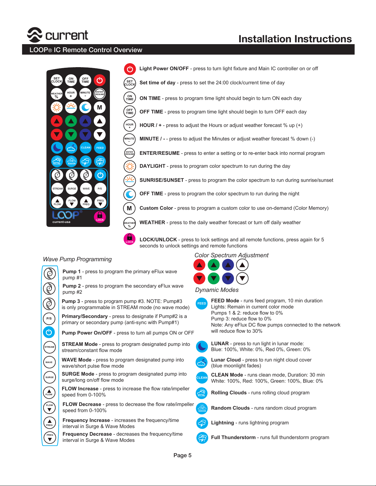
Light Power ON/OFF - press to turn light fixture and Main IC controller on or off
Color Spectrum Adjustment
CLEAN
SET
CLOCK
OFF
TIME
ON
TIME
M
1 2
3
HOUR
MINUTE
current-usa
+
-
H
H
ENTER
RESUME
WEATHER
%
®
FEED
CLEAN
LOCK
LOCK
Page 5
STREAM SURGE WAVE P/S
FLOW
FLOW
FREQ
FREQ
Set time of day - press to set the 24:00 clock/current time of day
ON TIME - press to program time light should begin to turn ON each day
OFF TIME - press to program time light should begin to turn OFF each day
HOUR / + - press to adjust the Hours or adjust weather forecast % up (+)
MINUTE / - - press to adjust the Minutes or adjust weather forecast % down (-)
ENTER/RESUME - press to enter a setting or to re-enter back into normal program
DAYLIGHT - press to program color spectrum to run during the day
SUNRISE/SUNSET - press to program the color spectrum to run during sunrise/sunset
OFF TIME - press to program the color spectrum to run during the night
Custom Color - press to program a custom color to use on-demand (Color Memory)
WEATHER - press to the daily weather forecast or turn off daily weather
LOCK/UNLOCK - press to lock settings and all remote functions, press again for 5
seconds to unlock settings and remote functions
RESUME
ENTER
Pump 1 - press to program the primary eFlux wave
pump #1
Pump 2 - press to program the secondary eFlux wave
pump #2
Pump 3 - press to program pump #3. NOTE: Pump#3
is only programmable in STREAM mode (no wave mode)
Primary/Secondary - press to designate if Pump#2 is a
primary or secondary pump (anti-sync with Pump#1)
Pump Power On/OFF - press to turn all pumps ON or OFF
STREAM Mode - press to program designated pump into
stream/constant flow mode
WAVE Mode - press to program designated pump into
wave/short pulse flow mode
SURGE Mode - press to program designated pump into
surge/long on/off flow mode
FLOW Increase - press to increase the flow rate/impeller
speed from 0-100%
FLOW Decrease - press to decrease the flow rate/impeller
speed from 0-100%
Frequency Increase - increases the frequency/time
interval in Surge & Wave Modes
Frequency Decrease - decreases the frequency/time
interval in Surge & Wave Modes
Full Thunderstorm - runs full thunderstorm program
Lightning - runs lightning program
Random Clouds - runs random cloud program
Rolling Clouds - runs rolling cloud program
CLEAN Mode - runs clean mode, Duration: 30 min
White: 100%, Red: 100%, Green: 100%, Blue: 0%
Lunar Cloud - press to run night cloud cover
(blue moonlight fades)
LUNAR - press to run light in lunar mode:
Blue: 100%, White: 0%, Red 0%, Green: 0%
FEED Mode - runs feed program, 10 min duration
Lights: Remain in current color mode
Pumps 1 & 2: reduce flow to 0%
Pump 3: reduce flow to 0%
Note: Any eFlux DC flow pumps connected to the network
will reduce flow to 30%
STREAM
WAVE
SURGE
FLOW
FLOW
FREQ
FREQ
Page 6
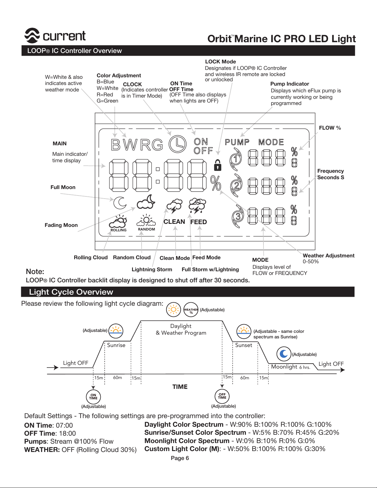
LOOP® IC Controller Overview
MODE
Pump Indicator
LOCK Mode
CLEAN
Color Adjustment
B=Blue
W=White
R=Red
G=Green
Displays which eFlux pump is
currently working or being
programmed
Displays level of
FLOW or FREQUENC
Y
Designates if LOOP
® IC Controller
and wireless IR remote are locked
or unlocked
MAIN
Main indicator/
time display
FEED
CLOCK
ON Time
OFF Time
Full Moon
Fading Moon
Rolling Cloud Random Cloud
Full Storm w/Lightning
Lightning Storm
Clean Mode
Feed Mode
Note:
LOOP® IC Controller backlit display is designed to shut off after 30 seconds.
W=White & also
indicates active
weather mode
FLOW %
Frequency
Seconds S
Weather Adjustment
0-50%
(OFF Time also displays
when lights are OFF)
(Indicates controller
is in Timer Mode)
Light Cycle Overview
Light OFF
TIME
15m
15m
15m
15m60m
60m
Moonlight
Sunrise
Daylight
& Weather Program
Sunset
ON
TIME
OFF
TIME
6 hrs.
Please review the following light cycle diagram:
(Adjustable)
(Adjustable)
(Adjustable)
(Adjustable)
(Adjustable)
(Adjustable - same color
spectrum as Sunrise)
ON Time: 07:00
OFF Time: 18:00
Pumps: Stream @100% Flow
WEATHER: OFF (Rolling Cloud 30%)
Daylight Color Spectrum - W:90% B:100% R:100% G:100%
Sunrise/Sunset Color Spectrum - W:5% B:70% R:45% G:20%
Moonlight Color Spectrum - W:0% B:10% R:0% G:0%
Custom Light Color (M): - W:50% B:100% R:100% G:30%
Default Settings - The following settings are pre-programmed into the controller:
WEATHER
%
Light OFF
Page 6
Orbit Marine IC PRO LED Light
TM
Page 7
Installation Instructions
LOOP® IC Controller Programming
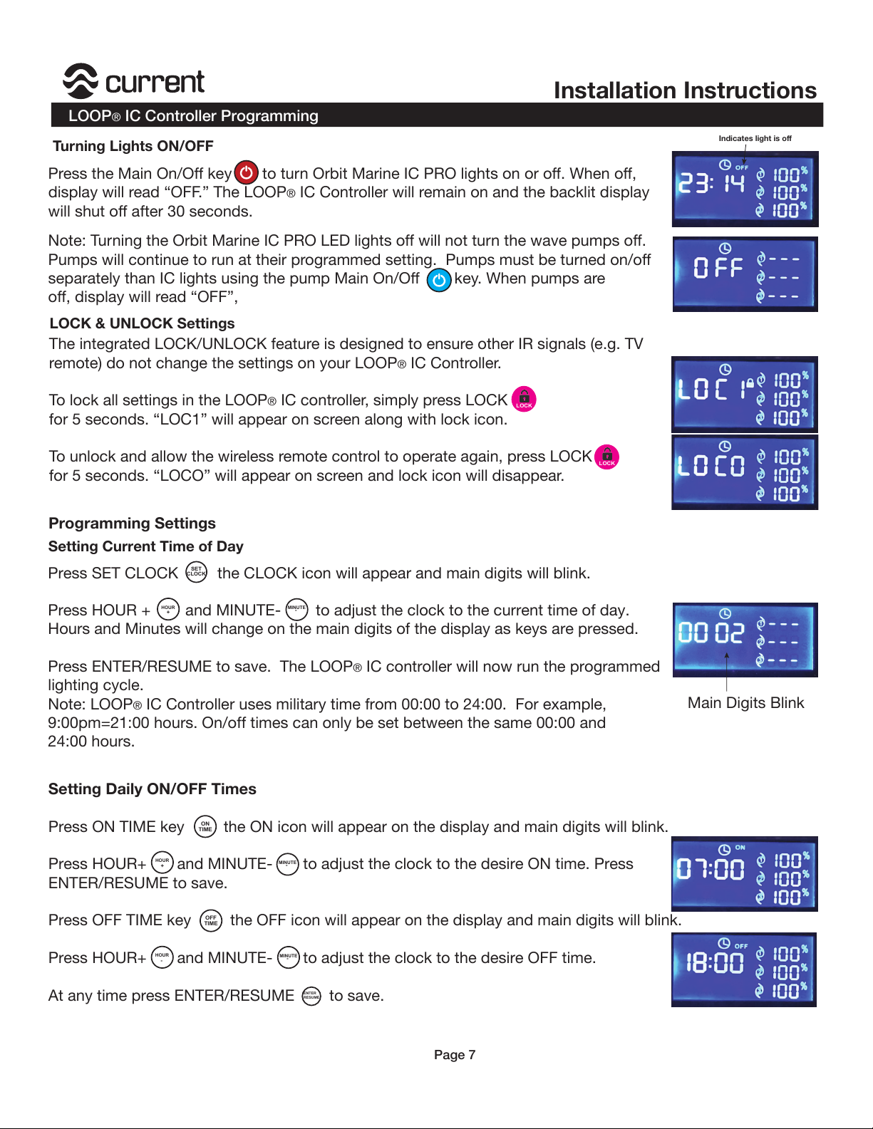
Turning Lights ON/OFF
LOCK
LOCK
Note: Turning the Orbit Marine IC PRO LED lights off will not turn the wave pumps off.
Pumps will continue to run at their programmed setting. Pumps must be turned on/off
separately than IC lights using the pump Main On/Off key. When pumps are
off, display will read “OFF”,
Press the Main On/Off key to turn Orbit Marine IC PRO lights on or off. When off,
display will read “OFF.” The LOOP® IC Controller will remain on and the backlit display
will shut off after 30 seconds.
The integrated LOCK/UNLOCK feature is designed to ensure other IR signals (e.g. TV
remote) do not change the settings on your LOOP
® IC Controller.
To lock all settings in the LOOP
® IC controller, simply press LOCK
for 5 seconds. “LOC1” will appear on screen along with lock icon.
To unlock and allow the wireless remote control to operate again, press LOCK
for 5 seconds. “LOCO” will appear on screen and lock icon will disappear.
LOCK & UNLOCK Settings
Setting Current Time of Day
Programming Settings
Press SET CLOCK the CLOCK icon will appear and main digits will blink.
Press HOUR + and MINUTE- to adjust the clock to the current time of day.
Hours and Minutes will change on the main digits of the display as keys are pressed.
Press ENTER/RESUME to save. The LOOP
® IC controller will now run the programmed
lighting cycle.
Note: LOOP
® IC Controller uses military time from 00:00 to 24:00. For example,
9:00pm=21:00 hours. On/off times can only be set between the same 00:00 and
24:00 hours.
SET
CLOCK
HOUR
MINUTE
+
-
Setting Daily ON/OFF Times
Press ON TIME key the ON icon will appear on the display and main digits will blink.
Press HOUR+ and MINUTE- to adjust the clock to the desire ON time. Press
ENTER/RESUME to save.
Press OFF TIME key the OFF icon will appear on the display and main digits will blink.
Press HOUR+ and MINUTE- to adjust the clock to the desire OFF time.
At any time press ENTER/RESUME to save.
HOUR
MINUTE
-
-
OFF
TIME
ON
TIME
ENTER
RESUME
HOUR
MINUTE
+
-
Main Digits Blink
Indicates light is off
Page 7
Page 8
LOOP® IC Controller Programming
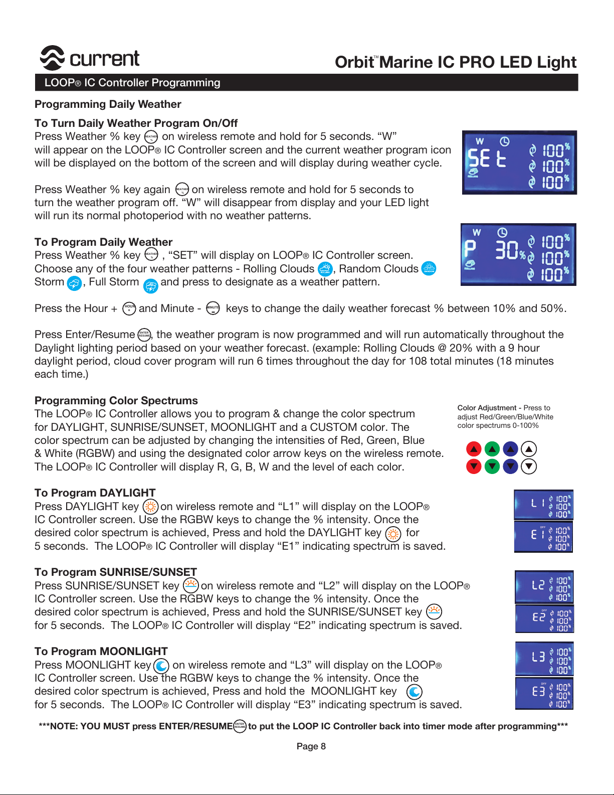
To Turn Daily Weather Program On/Off
Press Weather % key on wireless remote and hold for 5 seconds. “W”
will appear on the LOOP
® IC Controller screen and the current weather program icon
will be displayed on the bottom of the screen and will display during weather cycle.
Press Weather % key again on wireless remote and hold for 5 seconds to
turn the weather program off. “W” will disappear from display and your LED light
will run its normal photoperiod with no weather patterns.
To Program Daily Weather
Press Weather % key , “SET” will display on LOOP
® IC Controller screen.
Choose any of the four weather patterns - Rolling Clouds , Random Clouds
Storm , Full Storm and press to designate as a weather pattern.
Press the Hour + and Minute - keys to change the daily weather forecast % between 10% and 50%.
Press Enter/Resume , the weather program is now programmed and will run automatically throughout the
Daylight lighting period based on your weather forecast. (example: Rolling Clouds @ 20% with a 9 hour
daylight period, cloud cover program will run 6 times throughout the day for 108 total minutes (18 minutes
each time.)
Programming Color Spectrums
The LOOP
® IC Controller allows you to program & change the color spectrum
for DAYLIGHT, SUNRISE/SUNSET, MOONLIGHT and a CUSTOM color. The
color spectrum can be adjusted by changing the intensities of Red, Green, Blue
& White (RGBW) and using the designated color arrow keys on the wireless remote.
The LOOP
® IC Controller will display R, G, B, W and the level of each color.
To Program DAYLIGHT
Press DAYLIGHT key on wireless remote and “L1” will display on the LOOP
®
IC Controller screen. Use the RGBW keys to change the % intensity. Once the
desired color spectrum is achieved, Press and hold the DAYLIGHT key for
5 seconds. The LOOP
® IC Controller will display “E1” indicating spectrum is saved.
To Program SUNRISE/SUNSET
Press SUNRISE/SUNSET key on wireless remote and “L2” will display on the LOOP
®
IC Controller screen. Use the RGBW keys to change the % intensity. Once the
desired color spectrum is achieved, Press and hold the SUNRISE/SUNSET key
for 5 seconds. The LOOP® IC Controller will display “E2” indicating spectrum is saved.
To Program MOONLIGHT
Press MOONLIGHT key on wireless remote and “L3” will display on the LOOP
®
IC Controller screen. Use the RGBW keys to change the % intensity. Once the
desired color spectrum is achieved, Press and hold the MOONLIGHT key
for 5 seconds. The LOOP
® IC Controller will display “E3” indicating spectrum is saved.
MINUTE
HOUR
+
%
WEATHER
-
ENTER
RESUME
Color Adjustment - Press to
adjust Red/Green/Blue/White
color spectrums 0-100%
%
WEATHER
%
WEATHER
***NOTE: YOU MUST press ENTER/RESUME to put the LOOP IC Controller back into timer mode after programming***
Page 8
ENTER
RESUME
Programming Daily Weather
Orbit Marine IC PRO LED Light
TM
Page 9
Installation Instructions
LOOP® IC Controller Programming
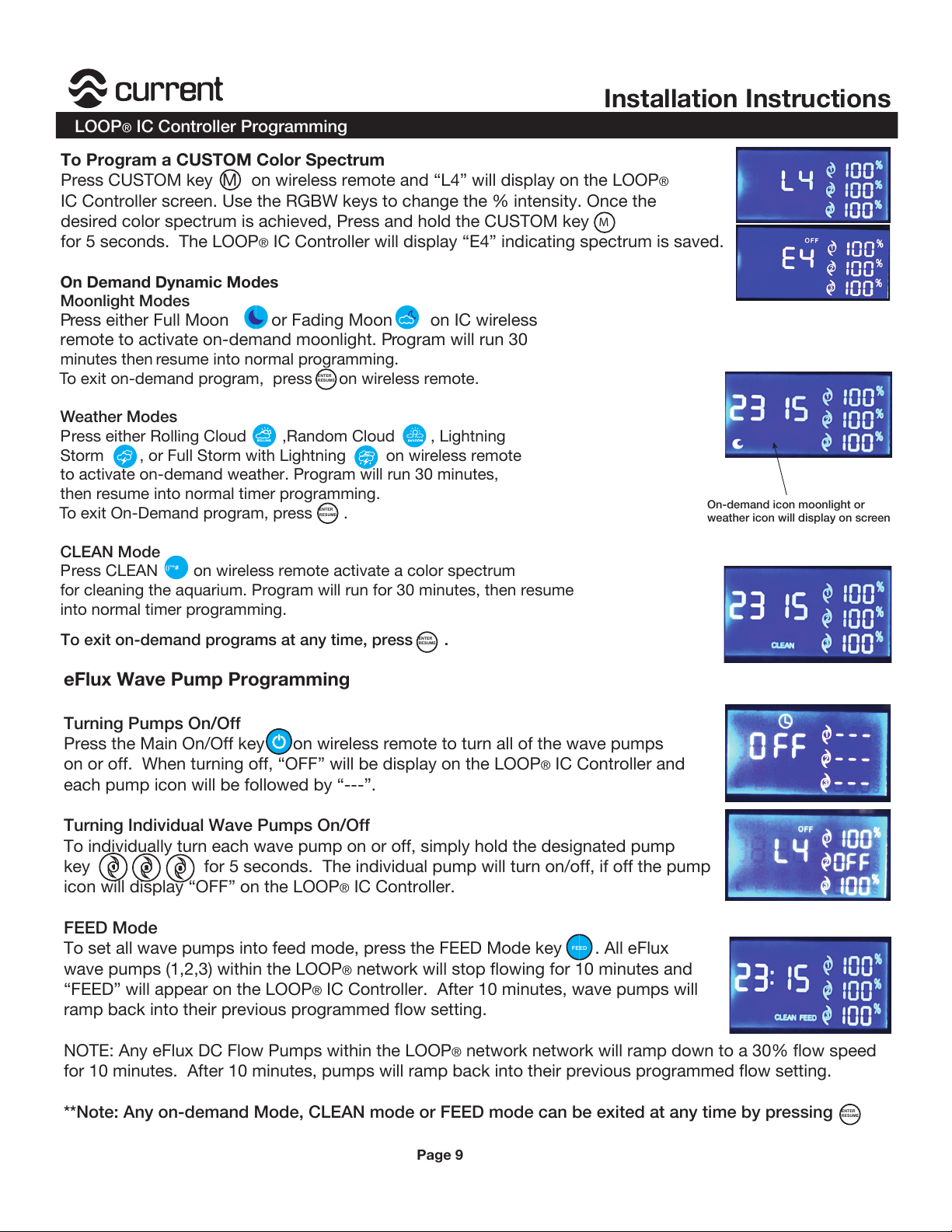
To Program a CUSTOM Color Spectrum
Press CUSTOM key M on wireless remote and “L4” will display on the LOOP
®
IC Controller screen. Use the RGBW keys to change the % intensity. Once the
desired color spectrum is achieved, Press and hold the CUSTOM key
for 5 seconds. The LOOP
® IC Controller will display “E4” indicating spectrum is saved.
On Demand Dynamic Modes
Moonlight Modes
Press either Full Moon or Fading Moon on IC wireless
remote to activate on-demand moonlight. Program will run 30
minutes then resume into normal programming.
To exit on-demand program, press on wireless remote.
Weather Modes
Press either Rolling Cloud ,Random Cloud , Lightning
Storm , or Full Storm with Lightning on wireless remote
to activate on-demand weather. Program will run 30 minutes,
then resume into normal timer programming.
To exit On-Demand program, press .
CLEAN Mode
Press CLEAN on wireless remote activate a color spectrum
for cleaning the aquarium. Program will run for 30 minutes, then resume
into normal timer programming.
To exit on-demand programs at any time, press .
ENTER
RESUME
ENTER
RESUME
ENTER
RESUME
()"*#
eFlux Wave Pump Programming
Turning Pumps On/Off
Press the Main On/Off key on wireless remote to turn all of the wave pumps
on or off. When turning off, “OFF” will be display on the LOOP
® IC Controller and
each pump icon will be followed by “---”.
Turning Individual Wave Pumps On/Off
To individually turn each wave pump on or off, simply hold the designated pump
key for 5 seconds. The individual pump will turn on/off, if off the pump
icon will display “OFF” on the LOOP
® IC Controller.
FEED Mode
To set all wave pumps into feed mode, press the FEED Mode key . All eFlux
wave pumps (1,2,3) within the LOOP
® network will stop flowing for 10 minutes and
“FEED” will appear on the LOOP
® IC Controller. After 10 minutes, wave pumps will
ramp back into their previous programmed flow setting.
NOTE: Any eFlux DC Flow Pumps within the LOOP
® network network will ramp down to a 30% flow speed
for 10 minutes. After 10 minutes, pumps will ramp back into their previous programmed flow setting.
**Note: Any on-demand Mode, CLEAN mode or FEED mode can be exited at any time by pressing
+
,
-
FEED
ENTER
RESUME
On-demand icon moonlight or
weather icon will display on screen
Page 9
M
Page 10
LOOP® IC Controller Programming
eFlux Wave Pump Programming
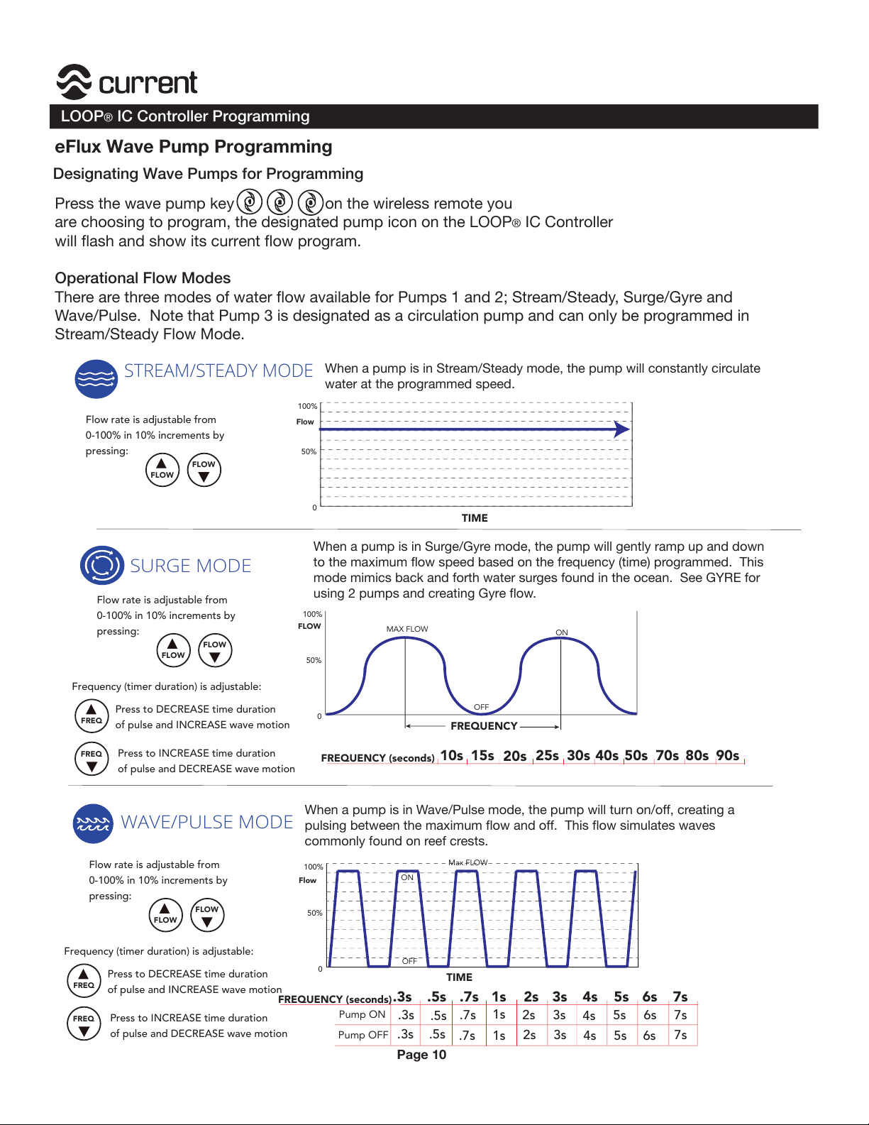
Press the wave pump key on the wireless remote you
are choosing to program, the designated pump icon on the LOOP
® IC Controller
will flash and show its current flow program.
Operational Flow Modes
There are three modes of water flow available for Pumps 1 and 2; Stream/Steady, Surge/Gyre and
Wave/Pulse. Note that Pump 3 is designated as a circulation pump and can only be programmed in
Stream/Steady Flow Mode.
0
1
2
TIME
0
100%
50%
Flow
Flow rate is adjustable from
0-100% in 10% increments by
pressing:
FLOW
FLOW
STREAM/STEADY MODE
When a pump is in Stream/Steady mode, the pump will constantly circulate
water at the programmed speed.
SURGE MODE
FREQ
FREQ
0
100%
50%
FLOW
Press to DECREASE time duration
of pulse and INCREASE wave motion
Press to INCREASE time duration
of pulse and DECREASE wave motion
FREQUENCY
10s
FREQUENCY (seconds)
15s
20s
25s 30s 40s 50s 70s 80s 90s
MAX FLOW
Frequency (timer duration) is adjustable:
WAVE/PULSE MODE
0
100%
50%
Flow
Pump OFF
Pump ON
.3s .5s
1s 2s 3s 4s 5s 6s 7s
.3s .5s
.7s
.3s
.5s
.7s
1s
1s
2s2s3s
4s
5s 6s 7s
3s
4s 5s 6s
7s
.7s
TIME
ON
FREQUENCY (seconds)
OFF
Max FLOW
ON
OFF
When a pump is in Surge/Gyre mode, the pump will gently ramp up and down
to the maximum flow speed based on the frequency (time) programmed. This
mode mimics back and forth water surges found in the ocean. See GYRE for
using 2 pumps and creating Gyre flow.
When a pump is in Wave/Pulse mode, the pump will turn on/off, creating a
pulsing between the maximum flow and off. This flow simulates waves
commonly found on reef crests.
Flow rate is adjustable from
0-100% in 10% increments by
pressing:
FLOW
FLOW
FREQ
FREQ
Press to DECREASE time duration
of pulse and INCREASE wave motion
Press to INCREASE time duration
of pulse and DECREASE wave motion
Frequency (timer duration) is adjustable:
Flow rate is adjustable from
0-100% in 10% increments by
pressing:
FLOW
FLOW
Designating Wave Pumps for Programming
Page 10
Orbit Marine IC PRO LED Light
TM
Page 11
Installation Instructions
LOOP® IC Controller Programming
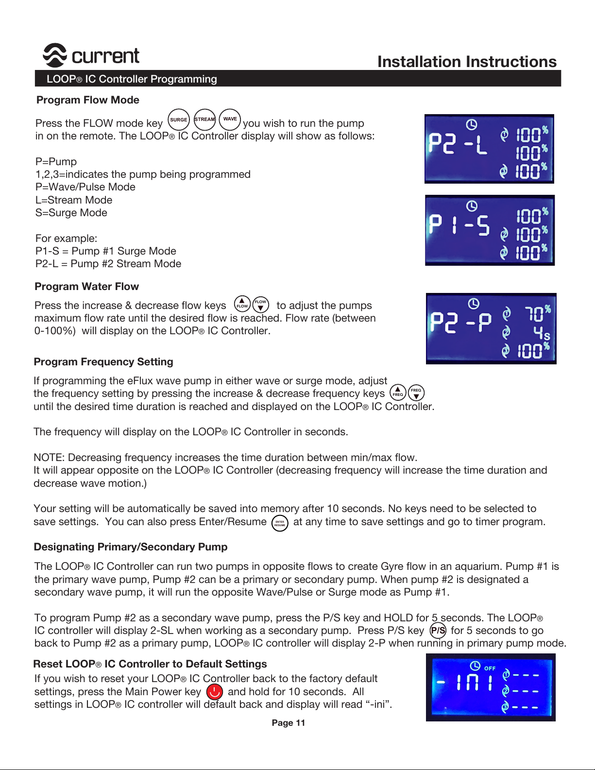
Press the FLOW mode key you wish to run the pump
in on the remote. The LOOP
® IC Controller display will show as follows:
P=Pump
1,2,3=indicates the pump being programmed
P=Wave/Pulse Mode
L=Stream Mode
S=Surge Mode
For example:
P1-S = Pump #1 Surge Mode
P2-L = Pump #2 Stream Mode
STREAM
SURGE
WAVE
Press the increase & decrease flow keys to adjust the pumps
maximum flow rate until the desired flow is reached. Flow rate (between
0-100%) will display on the LOOP
® IC Controller.
If programming the eFlux wave pump in either wave or surge mode, adjust
the frequency setting by pressing the increase & decrease frequency keys
until the desired time duration is reached and displayed on the LOOP® IC Controller.
The frequency will display on the LOOP
® IC Controller in seconds.
NOTE: Decreasing frequency increases the time duration between min/max flow.
It will appear opposite on the LOOP® IC Controller (decreasing frequency will increase the time duration and
decrease wave motion.)
Your setting will be automatically be saved into memory after 10 seconds. No keys need to be selected to
save settings. You can also press Enter/Resume at any time to save settings and go to timer program.
The LOOP
® IC Controller can run two pumps in opposite flows to create Gyre flow in an aquarium. Pump #1 is
the primary wave pump, Pump #2 can be a primary or secondary pump. When pump #2 is designated a
secondary wave pump, it will run the opposite Wave/Pulse or Surge mode as Pump #1.
To program Pump #2 as a secondary wave pump, press the P/S key and HOLD for 5 seconds. The LOOP
®
IC controller will display 2-SL when working as a secondary pump. Press P/S key for 5 seconds to go
back to Pump #2 as a primary pump, LOOP
® IC controller will display 2-P when running in primary pump mode.
FLOW
FLOW
FREQ
FREQ
ENTER
RESUME
If you wish to reset your LOOP® IC Controller back to the factory default
settings, press the Main Power key and hold for 10 seconds. All
settings in LOOP
® IC controller will default back and display will read “-ini”.
P/S
Program Flow Mode
Program Water Flow
Program Frequency Setting
Designating Primary/Secondary Pump
Page 11
Reset LOOP® IC Controller to Default Settings
Page 12
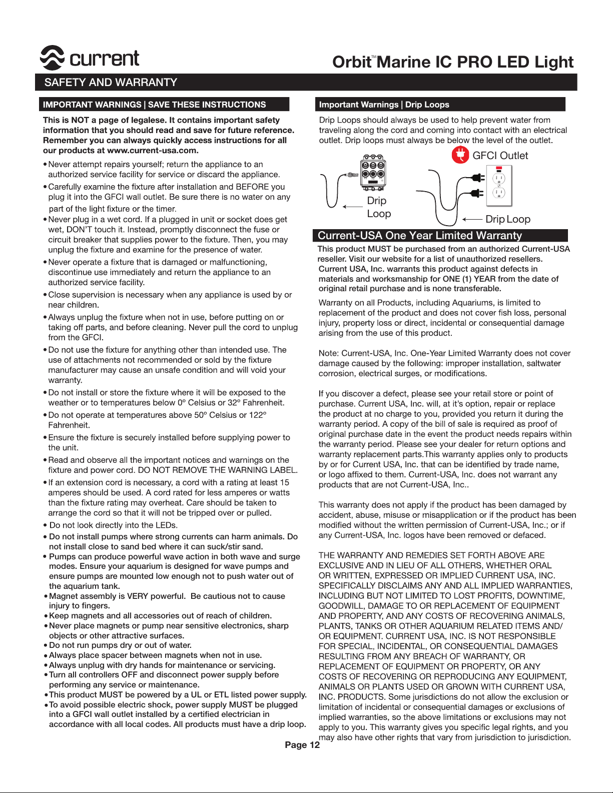
GFCI Outlet
Drip
Loop
P1P3
P2
Drip
Loop
D
C
Do not install pumps where strong currents can harm animals. Do
not install close to sand bed where it can suck/stir sand.
Pumps can produce powerful wave action in both wave and surge
modes. Ensure your aquarium is designed for wave pumps and
ensure pumps are mounted low enough not to push water out of
the aquarium tank.
Magnet assembly is VERY powerful. Be cautious not to cause
injury to fingers.
Keep magnets and all accessories out of reach of children.
Never place magnets or pump near sensitive electronics, sharp
objects or other attractive surfaces.
Do not run pumps dry or out of water.
Always place spacer between magnets when not in use.
Always unplug with dry hands for maintenance or servicing.
Turn all controllers OFF and disconnect power supply before
performing any service or maintenance.
This product MUST be powered by a UL or ETL listed power supply.
To avoid possible electric shock, power supply MUST be plugged
into a GFCI wall outlet installed by a certified electrician in
accordance with all local codes. All products must have a drip loop.
This product MUST be purchased from an authorized Current-USA
reseller. Visit our website for a list of unauthorized resellers.
Current USA, Inc. warrants this product against defects in
materials and worksmanship for ONE (1) YEAR from the date of
original retail purchase and is none transferable.
Current-USA One Year Limited Warranty
SAFETY AND WARRANTY
Page 12
Orbit Marine IC PRO LED Light
TM
 Loading...