

Page 1
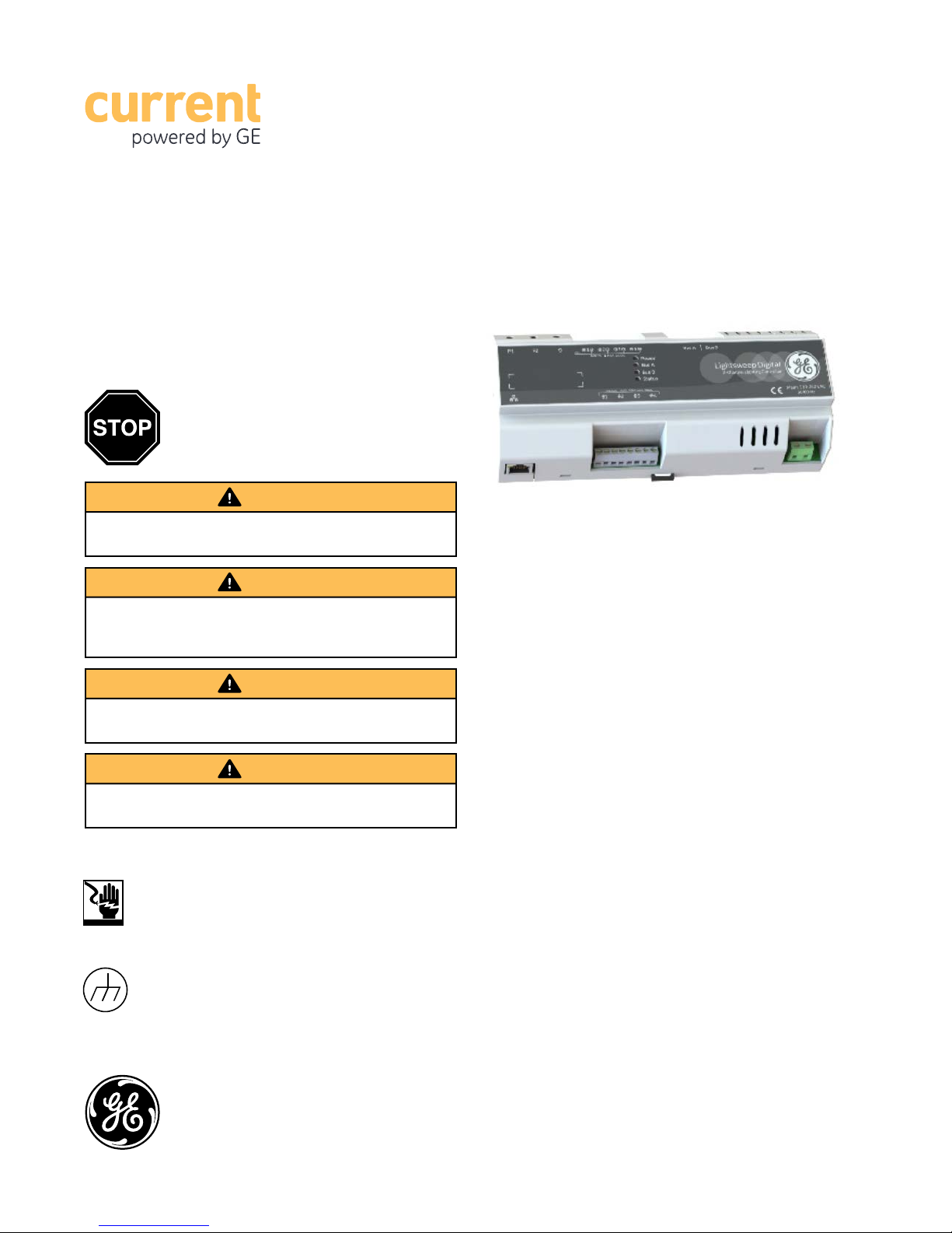
Lightsweep
Българската версия на инструкциите за инсталация и информация за
Българската версия на инструкциите за инсталация и информация за
безопасност могат да бъдат намерени на следния адрес:
Lightsweep™ Digital Controller
BEFORE YOU BEGIN
Read these instructions completely and carefully.
Save these instructions for future use.
WARNING
Risk of electrical shock. Disconnect power before service
installation, or maintenance of the product.
Installation Guide
CTRL020
™
Digital System
IMPORTANT
WARNING
Risk of fire. Follow all relevant IEC or UL instructions and
local building codes. Use only IEC or UL approved wire for
input/output connections.
WARNING
Seperation of Circuits. Install in accordance with National
Electric Code and local codes rules.
CAUTION
Risk of injury. Wear safety glasses and gloves during
installation and servicing.
Prepare Electrical Wiring
Electrical Requirements
The Lightsweep™ Digital Controller must be
connected to the mains supply according to its
ratings on the product label.
Grounding Instructions
The grounding and bonding of the overall system
shall be done in accordance with National Electric
Code (NEC) Article 600 and local codes.
To ensure the product warranty is valid, please ensure
all installation instructions and environmental conditions
for storage and operation are complied with.
Only GE trained contractors can install the product.
Must be installed in a Cabinet.
BG-
безопасност могат да бъдат намерени на следния адрес:
HR-Hrvatska verzija priručnika za ugradnju i sigurnosnih informacija nalazi se na sljedećoj
lokaciji:
CS- Návod k montáži a bezpečnostní informace v češtině najdete zde:
DA-Den danske version af installationsvejledningen og sikkerhedsoplysninger kan ndes på
følgende placering:
NL- De Nederlandse versie van de installatie-instructies en veiligheidsinformatie kan op de
volgende locatie worden gevonden:
ET- Eestikeelse paigaldusjuhendi ja ohutusnõuded leiate aadressilt:
EN-The English version of the installation instruction and safety information can be found at
the following location:
FI-
Asennusohjeiden ja turvallisuustietojen suomenkielinen versio löytyy seuraavasta paikasta:
FR- La version française des instructions d’installation et informations de sécurité est
disponible à l’adresse suivante :
DE- Die deutsche Version der Installationsanleitung und Sicherheitsinformationen nden Sie
in folgendem Verzeichnis:
EL-
ληροφοριών ασφάλειας στην εξής τοποθεσία:
HU- A telepítési útmutató és a biztonsági információk magyar nyelvű változata az alábbi
címen található:
IT- La versione italiana del manuale di installazione e sicurezza può essere reperita nella
seguente sezione:
LV- Uzstādīšanas instrukciju un drošības informāciju latviešu valodā var atrast šeit:
LT- Lietuvišką diegimo instrukcijos ir saugos informacijos versiją galima rasti šioje vietoje:
PL- Polską wersję instrukcji instalacji oraz informacje dotyczące bezpieczeństwa można
znaleźć w następującej lokalizacji:
PT- A versão em Português das instruções de instalação e das informações de segurança
pode ser encontrada na seguinte localização:
RO-Versiunea în limba română a instrucţiunilor de instalare şi a informaţiilor de siguranţă
pot găsite la:
SK- Slovenskú verziu montážnej príručky a bezpečnostných inštrukcií nájdete na nasledu
júcej lokalite:
SL-
Slovenska različica navodil za namestitev in varnostnih navodil se nahaja na naslednji strani:
ES- La versión española de las instrucciones de instalación y la información sobre seguridad
puede encontrarse en la siguiente ubicación:
SV- Ni hittar den svenska versionen av installationsanvisningarna och säkerhetsinformationen
på följande plats:
Page 2
Technical Data
Key Functions
Type: Lightsweep™ Digital Controller
Product Code: LL-DC
SKU: 93037756
Dimensions: W x L x H: 213 x 90 x 58 mm
Weight: 400 grams
Housing: DIN (EN50022) rail mounted, M12
Warranty: 5 years
Powering Device
Power Input: 110 - 240 V AC 50/60Hz *
Fuse Protection - Internal: 1A load, T/SLO-BLO, VDE/UL rated
Electrical Safety Class: EU Safety Class II if installed in
an appropriate mounting box
Terminals: Screw terminals
Terminal Assignment:
Wire size: 30-12 AWG (0.05-3 mm2)
(solid or stranded wire with sleeve)
See wiring diagrams and
information printed on unit. If
* In case of 277V usage step down transformer needed. Please find the compatible
type in table below. Usage of other step down transformer is possible. Please contact
your local support for more information.
incorrectly connected there is a risk
of failure, malfunction or destruction.
Compatible Step Down Transformer
MANUFACTURER T YPE
Hatch Lighting LS120-75EN-277
Product Availability
SKU DESCRIPTION
93037756 LightSweep™ Digital Controller LL-DC
ARTICLE
NO.
Operating Conditions
Operating Temperature: 0°C - 45°C
Relative Humidity: 90%, non-condensing
IP Rating: 20
Interfaces
Digital Interface: Two independent digital
communication and power supply
interface. The power supply is
feeding 18,5V/175mA DC, +/-10%,
it has electrical current limitation
and protection against overheating
and overvoltage. DALI 2.0 devices
can be connected, please contact
your local support for compatible
device’s list.
Relay Outputs: 4 outputs as Solid state dry contacts,
24-240V AC or DC nominal load,
400V/50mA peak, galvanically
separated contacts
(VISO= max. 4.5 kV between contacts)
Input Interface: 4-channel Max. 25VDC
Data Interface: 1 Ethernet connector: RJ45, 10Mbit/s
full duplex
Data Cable Routes: CAT5 and higher grade, max. 100
meter cable length
Controller Network: Up to 10 Lightsweep Digital Controller
can form a network
Product
Certifications
E486320
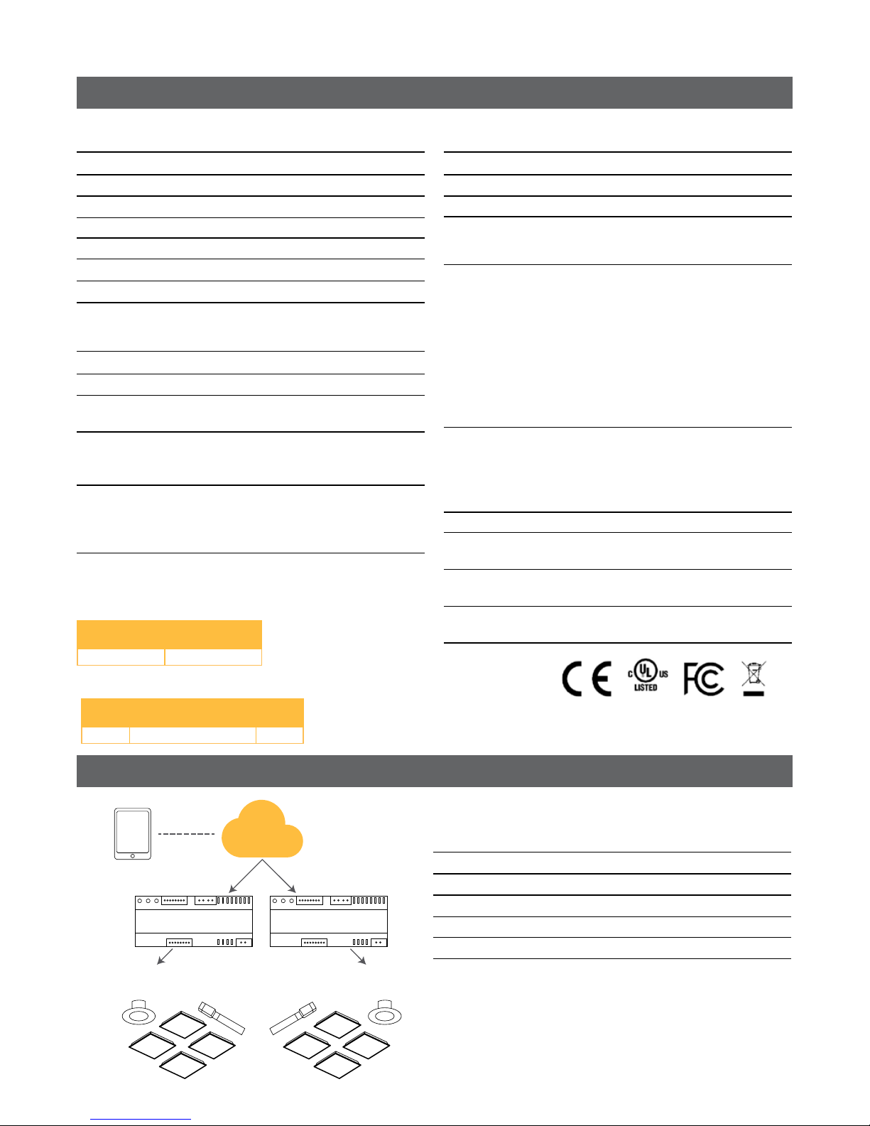
System Components
Digital
TM
TM
Lightsweep
Digital
Switch
Interface
Mobile
device
LightsweepTM Digital
network
TM
Lightsweep
Digital
Multisensor
Luminaires Luminaires
Lightsweep
local network
LANLAN
Lightsweep
Digital
Switch
Interface
TM
LightsweepTM Digital
network
Lightsweep™ Digital system components:
SKU DESCRIPTION ARTICLE NO.
93037756 Lightsweep™ Digital Controller LL-DC
93045357 Lightsweep™ Digital Multisensor Recessed LL-DMS2-CR
93037758 Lightsweep™ Digital Multisensor Surface Mounted LL-DMS2-CS
93037759 Lightsweep™ Digital Switch Interface for up to 3 buttons LL-DSW-PB3
93037760 Lightsweep™ Digital Switch Interface for up to 9 buttons LL-DSW-PB9
TM
Lightsweep
Digital
Multisensor
Page 3
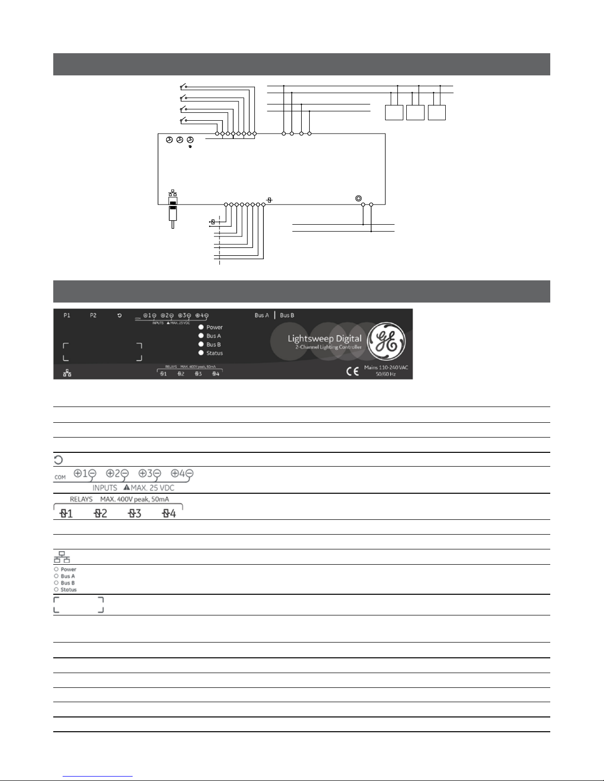
Wiring Diagram
Bus A
mains 110-240VAC ~50/60HzL
N
RJ45
AC~
Bus B
INPUTS MAX. 25VDC
1234
1 234
RELAYS MAX. 400V peak, 50mA
THERNET
Bus A
+-+-+-+-
COM
Bus A
Bus B
Bus B
LightsweepTM Digital Controller
DRIVER
Fixture
Lightsweep
TM
Digital Switch
Interface
+-+-
P1
24V - 240V AC/DC
(max. 50mA)
DRY CONTACTS
P2
Lightsweep
TM
Digital
Multisensor
Marking
Check marking on the
front label of device:
Marking Definition
Mains 110-240 VAC / 50/60 Hz Power In
P1 Pushbutton 1 (Corresponding to Bus A)
P2 Pushbutton 2 (Corresponding to Bus B)
Pushbutton - Reset Device
Input Terminals 1. - 4.
Dry Contacts
Output terminals 1.-4.
Solid state relays for external relays (External relays max. 400V peak, 50mA)
Bus A Terminal for Digital bus ‘A’
Bus B Terminal for Digital bus ‘B’
Ethernet Connector
Indicator LED for feedback in operation
See explanation below.
Place for MAC/ individual ID of device
Notes
Purpose of the Control: Operating Control
Method of Mounting Control: Independently Mounted Control for panel mounting
Type of action and additional features: Type 1
Control Pollution Degree: 2
Software Class and Structure: Class A
Rated Impulse Voltage: 2500
Page 4
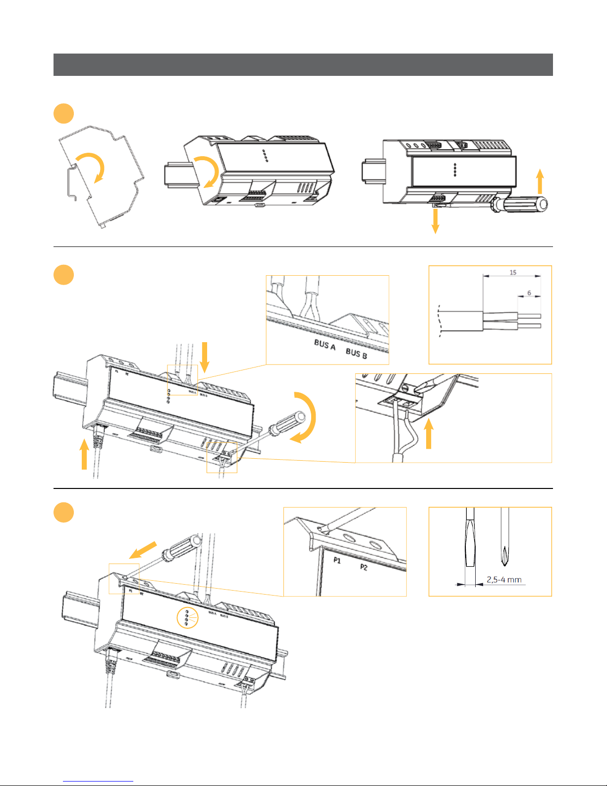
Installation
Strip wires as shown
on illustration.
Mains
110-240VAC ~50/60Hz
Important! Must be installed in a Cabinet.
1
2
Strip wires as shown
on illustration.
3
Mains
110-240VAC ~50/60Hz
Short press P1/P2 to start testing DIGITAL A/B Bus: lamps
Short press P1/P2 to start testing DIGITAL A/B
start dimming up and down on the bus until another
Bus: lamps start dimming up and down on the
short press is performed or 5-minute timer is expired.
bus until another short press is performed or
Meanwhile ‘DIGITAL A/B’ LED is blinking purple
5-minute timer is expired. Meanwhile ‘DIGITAL
A/B’ LED is blinking purple
Page 5
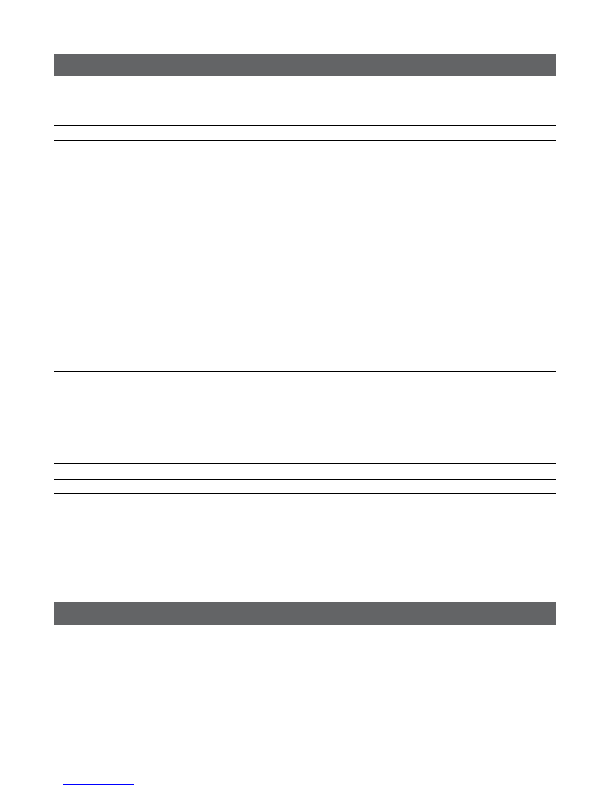
Connecting Digital Devices
Cable length limitations, Digital bus (control interfaces in accordance with 15.5 of IEC 61347-2-3:2011):
Conductor x-section, AWG/mm2, copper
Cable length, ft./m 310/95 390/120 620/190 790/240 1250/375*
*overall cable length above 1000ft/300m shall be avoided
DC resistance must not exceed 4Ω; according to IEC62386-101:2014.
Both Electrical and Logical limitations of Digital bus shall be considered when sizing / designing of the lighting control system.
Electrical limitations of each Digital bus
Max current load on each bus = 175mA
When connecting devices calculate power consumption of
the devices on the bus
• Control Gear: 2 mA**
• Lightsweep™ Digital Switch Interface: 2 mA
• Lightsweep™ Digital Multisensor 2: 3 mA
18/.75 17/1 15/1.5 14/2 12/3*
Logical limitations of each Digital bus
• Max number of Digital control gears applicable per bus: 64 pcs
• Max number of Digital input devices applicable per bus: 64 pcs
Input devices are GE Digital switches and sensors. In terms
of connecting 3rd party Digital devices please contact
support.
Wiring Relay outputs
Maximum cable length of relay outputs: DC resistance must not exceed 10Ω (see table below)
Cable length limitations, relay drive outputs:
Conductor x-section, AWG/mm2, copper
Cable length, ft./m 40/12 100/30 250/75 1000/300 2000/600 3000/900
30/.05 26/.125 23/.25 17/1 14/2 12/3
Wiring Input interfaces on controller
Warning: negative terminals are common internally. Loops should be avoided
Maximum cable length for inputs: wiring DC resistance must not exceed 100Ω
Cable length limitations, analog control inputs (negative terminals are common internally):
Conductor x-section, AWG/mm2, copper
Cable length, ft./m 500/150 1200/375 2500/750 10000/3000 20000/6000 31000/9000
**care should be taken applying cable lengths above 1650ft/500m as it can harmfully inuence stability.
30/.05 26/.125 23/.25** 17/1** 14/2** 12/3**
Separation of circuits
Warning: the wiring shall be installed in accordance with National Electric Code and local codes rules; the power wiring
must be separated accordingly from the class 2 signal wiring
Power wiring - AC power input and the relay outputs
Signal wiring - Ethernet, input interfaces and Digital Bus A/B
Network Connectivity
Lightsweep™ system requires wired network for operation
and wireless (Wi-Fi) network for commissioning and setup
(In case of standalone deployment, this can be a temporary
network).
Lightsweep™ devices should be placed into an independent
broadcast domain in the network, separated from any other
devices and communications. These Controllers can obtain
their IP addresses with DHCP, therefore an active IPv4 DHCP
service should be available in this network segment. Static
IP addresses are not supported.
The hand held device with the commissioning application
should be connected to the same network segment. The
proper Wi-Fi coverage in the whole commissioning area is
an essential need.
Page 6
Device Status Indicators
LED signals
Power LED:
• BLUE = device is powered and in operation
Bus A/Bus B:
• BLUE = Bus status is ok
• Blinking BLUE = communication on the Bus
• RED = Bus error (short)
• Blinking RED = More device than allowed on the Bus
• Blinking PURPLE = Bus test in progress
• Continuous PURPLE = PB1/2 push is active
Status:
• Continuously blinking BLUE = status OK
• Blinking blue quickly = Controller is booting or busy
• Blinking purple slowly = Controller is searching for
endpoints
• Continuous BLUE or OFF = Controller is frozen, perform
a reset
• Blinking red quickly = TLS handshake / Authentication
Test & Reset Installation
TEST of connected devices
• PB1 (pushbutton 1) short press: start testing Bus A bus:
lamps start dimming up and down on the bus until
another short press is performed or 5-minute timer is
expired. Meanwhile ‘Bus A’ LED is blinking purple.
• PB2 (pushbutton 2) short press: start testing Bus B bus:
lamps start dimming up and down on the bus until
another short press is performed or 5-minute timer is
expired. Meanwhile ‘Bus B’ LED is blinking purple.
Real Time Clock
In case of power outage controller can keep the set internal clock. Retention time: 1 week.
RESET functionalities
• (reset button) short press: restart controller (HW reset,
no software conguration impact)
• PB1 long press (min 10 seconds): reset all Digital devices,
control gears + other devices to reset value on Bus A
• PB2 long press (min 10 seconds): reset all Digital devices,
control gears + other devices to reset value on Bus B
• PB1 + PB2 Long press (min 10 seconds) = reset controller
to factory defaults: empty ash conguration database,
reset passwords and run self-test. All indicator LEDs blink
4 times when device reset.
Failure Modes & Quick Repair
# Statement Take action
1 Controller do not react on buttons and status LED is continuous
BLUE or OFF. on device
2 If Bus A/B indicator LED is continuously RED, then Bus error. Check Digital bus wiring voltage drop,
wiring short circuit or endpoint limitation
3 If Bus A/B indicator LED is Blinking RED, then controller has more Check Digital device limitation
Digital device on the bus than allowed
4 If two lamps work together than the same short address was set. Reprogram driver or reset Bus A or B by
long-press on PB 1 or 2
5 If the power indicator LEDs ashing up blue for a few second and The controller cannot be repaired locally.
then all indicator LEDs are dark. Contact GE support.
6 If all indicator LEDs are dark.
Push reset button or power o and
Check supply voltage. Contact GE support.
Page 7

Legal Disclaimer
For Legal disclaimer please visit our website.
Contact Information:
Webpage: currentbyge.com
For further information contact your local sales.
All trademarks are the property of their respective owners. Information provided is subject to
change without notice. All values are design or typical values when measured under laboratory
conditions. Current, powered by GE is a business of the General Electric Company.
© 2018 GE.
www.currentbyge.com CTRL020 (Rev 09/05/18)
 Loading...