

Page 1
FLOTON ST20 USER MANUAL
Sleep Apnea Breathing Therapy Device
ENGLISH
Page 2
Floton Auto CPAP
2
SYMBOL KEY 6
CAUTIONS AND WARNINGS 7
CAUTIONS! 7
WARNINGS! 8
LIABILTY 9
INTRODUCTION 10
INTENDED USE 10
CONTRAINDICATIONS 10
DESCRIPTION OF THE DEVICE AND HUMIDIFIER 11
FLOTON ST20 11
FRONT AND BACK VIEW 12
CONTROL PANEL 13
HUMIDIFIER 14
ACCESSORIES 15
ACCESSORIES AND PARTS 16
CONNECTING THE SYSTEM 16
HUMIDIFIER 17
MASK 17
Page 3
Floton Auto CPAP
3
PARAMETERS, KEYS AND DISPLAY 18
PARAMETERS 18
KEYS 19
ON/OFF KEY 19
INPUT KEYS 19
RETURN KEY 19
DISPLAY 20
MONITORING DISPLAY 20
MODE DISPLAY (ST/T/S/APCV/CPAP) 20
RAMP AND AUTO DISPLAY 20
FUNCTIONS THE DEVICE 21
I-SLOP (SPEED OF RISING PRESSURE) 21
E-SENS (SENSITIVITY OF EXPIRATION TRIGGERING) 21
SPONTANEOUS MODE: SMODE 21
TIMED MODE : TMODE 21
CPAP MODE 21
ST MODE / SPONTANEOUS-TIMED MODE 22
AUTOMATIC MODE 22
PRESSURE CONTROL MODE: APCV (ASSISTED PRESSURE CONTROL VENTILATION) 22
RAMP FUNCTION 22
ALARMS 23
POWER FAILURE 23
Page 4
Floton Auto CPAP
4
CHECKING THE POWER FAILURE ALARM 23
LEAKAGE 23
CLEANING AND MAINTENANCE 24
CLEANING THE FLOTON ST20 24
CHANGING THE FLOTON ST20 CLOCK BATTERY 24
CLEANING THE HUMIDIFIER 24
HUMIDIFIER FUSE 25
CHANGING FILTER 25
TROUBLESHOOTING 26
SERVICE 29
SPECIFICATIONS 29
DISPOSAL 30
QUALITY WARRANTY ERROR! BOOKMARK NOT DEFINED.
ELECTRIC MAGNETIC INFORMATION 31
GUIDANCE AND MANUFACTURERS DECLARATION OF ELECTROMAGNETIC IMMUNITY FOR EQUIPMENT AND SYSTEMS THAT ARE NOT LIFE SUPPORTING 31
RECOMMENDED SEPARATION DISTANCES BETWEEN PORTABLE AND MOBILE RF COMMUNICATIONS EQUIPMENT AND THE FLOTON AUTO CPAP 34
Page 5
Floton Auto CPAP
5
DISCLAIMER OF WARRANTY AND LIMITATION OF CURASA ERROR! BOOKMARK NOT DEFINED.
CONTACT DETAILS 35
Page 6
Floton Auto CPAP
6
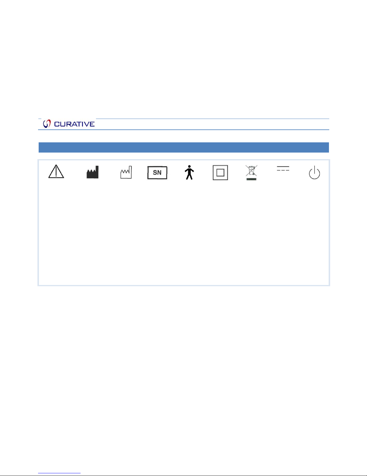
SY MBO L K EY
Attention!
Consult
accompanying
documents
Manufacturer
Date of
manufacture
Serial
number
Type B
applied part
Class II
Double
insulated
The device,
accessories
and the
packaging
have to be
disposed
correctly at
the end of
the usage.
Please
follow Local
Laws or
Regulations
for disposal
DC Power
Standby
Page 7
Floton Auto CPAP
7
CA UTI ONS AN D WARNI NGS
CA UTI ONS !
This device is restricted to sale by or on the order of a physician.
Do not use the device before the recommended therapeutic pressure is prescribed by a physician.
The device should be used with the external AC/DC adapter provided by manufacturer. Use of other AC/DC adapters may
damage the device or cause fire and electric shock hazards.
To prevent water entering the breathing circuit connection on the mask, the device must always be positioned below the
head.
Do not use the device at room temperatures above 35°C. If the device is used when temperature is above 35°C then the
temperature of the airflow may exceed 41°C, which could cause thermal irritation or injury to the patient’s airway.
Do not place the device near any items (curtains, bedding, couch) or heating devices (air conditioners, radiators, vents) that
may disrupt the airflow around the device.
Before carrying or packing the device you must empty the humidifier of water
The device should only be used with marked parts provided or recommended by your authorized dealer.
Check the alarm function regularly and if the device has not been used for a long time please check the power failure alarm
before use. If the Power failure alarm is invalid the device must be left in stand-by mode or left running for at least 12 hours
before checking the alarm again to make sure it is functioning normally.
If the device has recently been placed in a very hot or very cold environment, wait for 2 hours to allow temperature to
normalize before switching the device on.
The device can only be operated at temperatures between 5°C and 35°C.
Page 8

8
Sleep Apnea Breathing Therapy Device
User Manual
8
WA RNI NGS !
The device cannot be used whilst mobile.
This device is for adult use only and not for use by children or persons with certain disabilities who would require supervision
in order to use the device safely.
The device cannot be used for life support.
Do not use the device in the presence of nitrous oxide or flammable anesthetic mixtures in combination with oxygen or air.
In the event that the device noise level becomes higher than normal, the devices output of air becomes too hot, the device
has an abnormal smell or if any part of the device becomes broken, stop using it immediately contact an authorized dealer.
The device can only be switched off completely when the power supply is disconnected from the wall socket.
Make sure the exhalation opening in the mask or swivel is open so that the exhaled air containing CO2can escape.
To avoid rebreathing do not wear the mask for more than 3 minutes when the device is not switched on. (Note. At low
pressures the airflow may not be sufficient to remove all exhaled gas (CO2) therefore some rebreathing may occur.) Relevant
to curative?
The air inlet of the device should never be covered.
To avoid electric shock:
o Do not use the device if the device if the casing or cables are damaged.
o Do not use the device of it has been dropped in water.
o Keep device away from water.
o Before cleaning the device pull the power plug out of the socket.
Page 9

9
Sleep Apnea Breathing Therapy Device
User Manual
9
This device is for single patient use only and should not be shared with other patients.
If the patient experiences mucous membrane dryness in the nose and pharynx, frontal sinus trouble, earache, a running nose
or skin sensitivity etc. you should consult your physician immediately.
Operation of the device may be adversely affected by:
- Electromagnetic fields exceeding the level of 3V/m in the test conditions of EN 60601-1-2
- The operation of high frequency (diathermy) equipment.
- Defibrillators, or short wave therapy equipment
- Radiation (e.g., X-ray, CT)
- Magnetic fields (e.g., MRI).
- Do not sterilize the device with high pressured steam
LI ABI LTY
The manufacturer shall not be held liable for any damages in case of:
Tampering, modifying, adding expansion features or repair by persons who have not been authorized by the manufacturer.
Using accessory or spare parts that are not recommended by us, or not officially registered.
Using the device in a way that was not instructed in the manual.
Page 10

10
Sleep Apnea Breathing Therapy Device
User Manual
10
IN TRO DUC TIO N
IN TEN DED US E
The Floton ST20 respiratory sleep apnea breathing therapy device is for use by patients with sleep apnea or hypopnea syndrome to
reduce the frequency of sleep apnea, hypopnea and increases nocturnal SaO2.
It provides a stable continuous positive airway pressure whilst the humidifier provides warm and humid air which helps to avoid
nose and airway dryness increasing the comfort for the patient.
The therapeutic pressure is prescribed by a physician according to patient’s condition.
CONTR AIN DIC ATI ONS
The use of positive airway pressure may be contraindicated if the patient suffers from the following pre existing conditions:
Pneumothorax
Pneumomediastinum (Air in mediastinum)
Cerebrospinal fluid leakage
Pneumocephalus
Extremely low blood pressure or shock
Confusion or coma resulting in the patient not been able to co-operate with or accept the mask
Excessive secretions in the airway as well as not coughing effectively and weak voluntary breathing.
Page 11
11
Sleep Apnea Breathing Therapy Device
User Manual
11
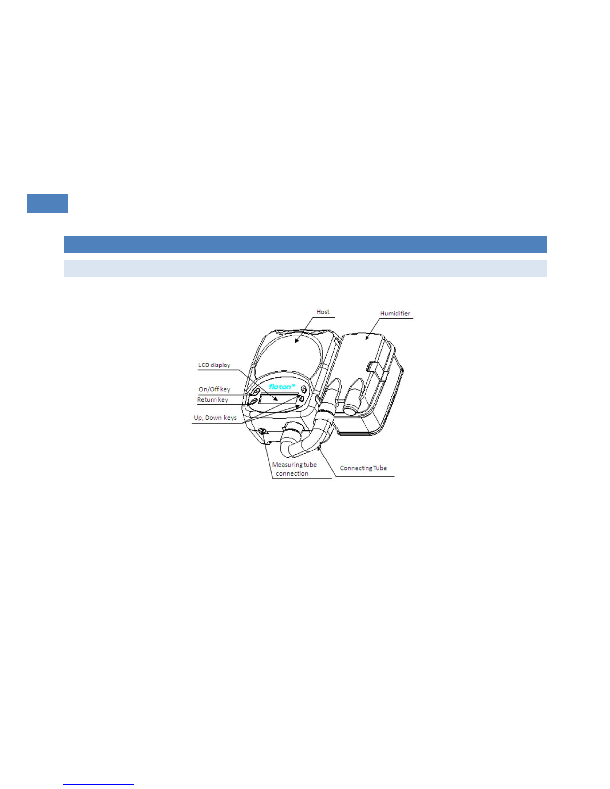
DE SCR IPT ION OF THE DE VIC E A ND HUM IDIF IER
FL OTO N S T20
Page 12
12
Sleep Apnea Breathing Therapy Device
User Manual
12
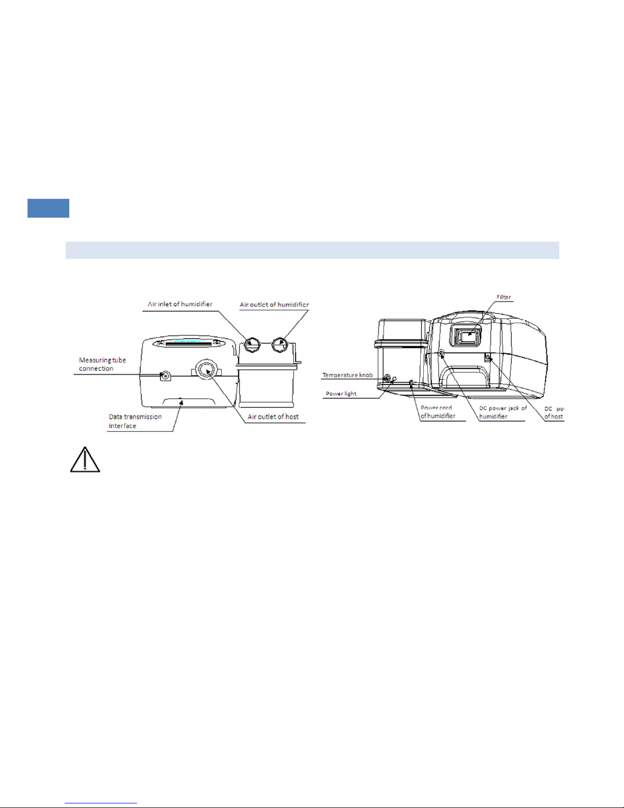
FR ONT AN D B ACK VI EW
Front
Back
Attention! The data transmission interface is only used during production or service when transmitting data to RS232 or
the USB of a PC.
Equipment connected to the analog or digital interfaces must comply with the respective IEC standards (e.g. IEC 950 for data
processing equipment and IEC 60601-1 for medical equipment). All configurations shall comply with the current version of the
standard for SYSTEMS IEC 601-1-1. If you are in doubt consult the technical service department or your local representative. RS232
and the USB port are only for technical use.
Page 13
13
Sleep Apnea Breathing Therapy Device
User Manual
13
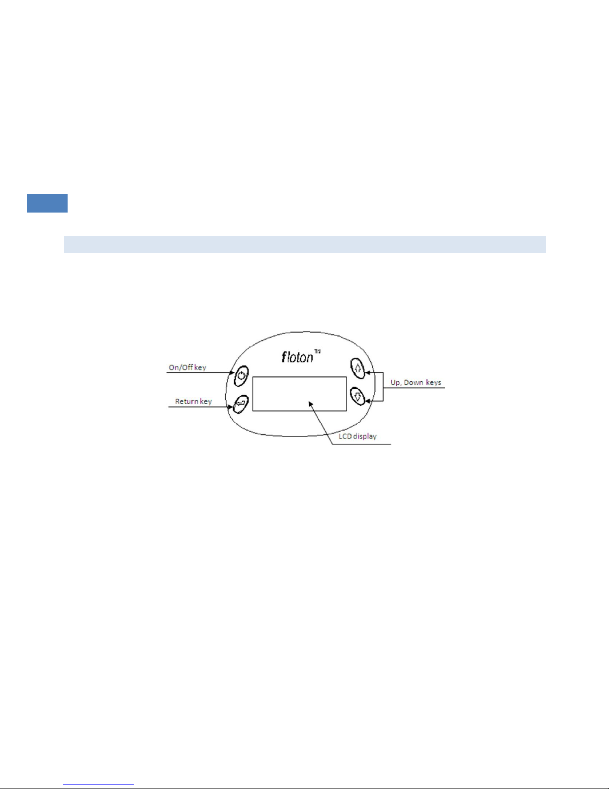
CONTR OL PAN EL
Page 14
14
Sleep Apnea Breathing Therapy Device
User Manual
14
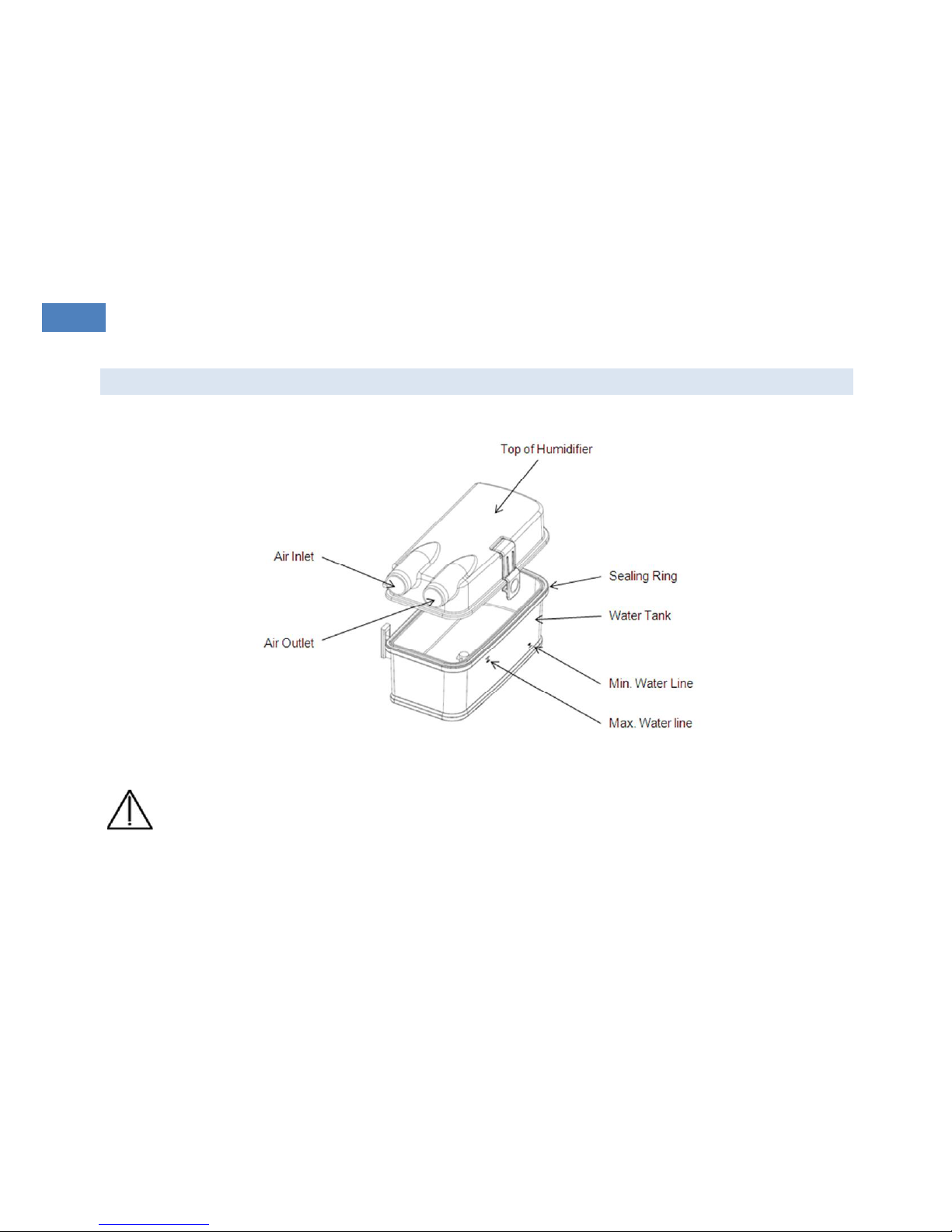
HU MID IFI ER
Warning! The humidifiers DC power jack can only be used to connect to the device with the provided power cable for
the humidifier. Do not connect it with the other devices.
Page 15
15
Sleep Apnea Breathing Therapy Device
User Manual
15
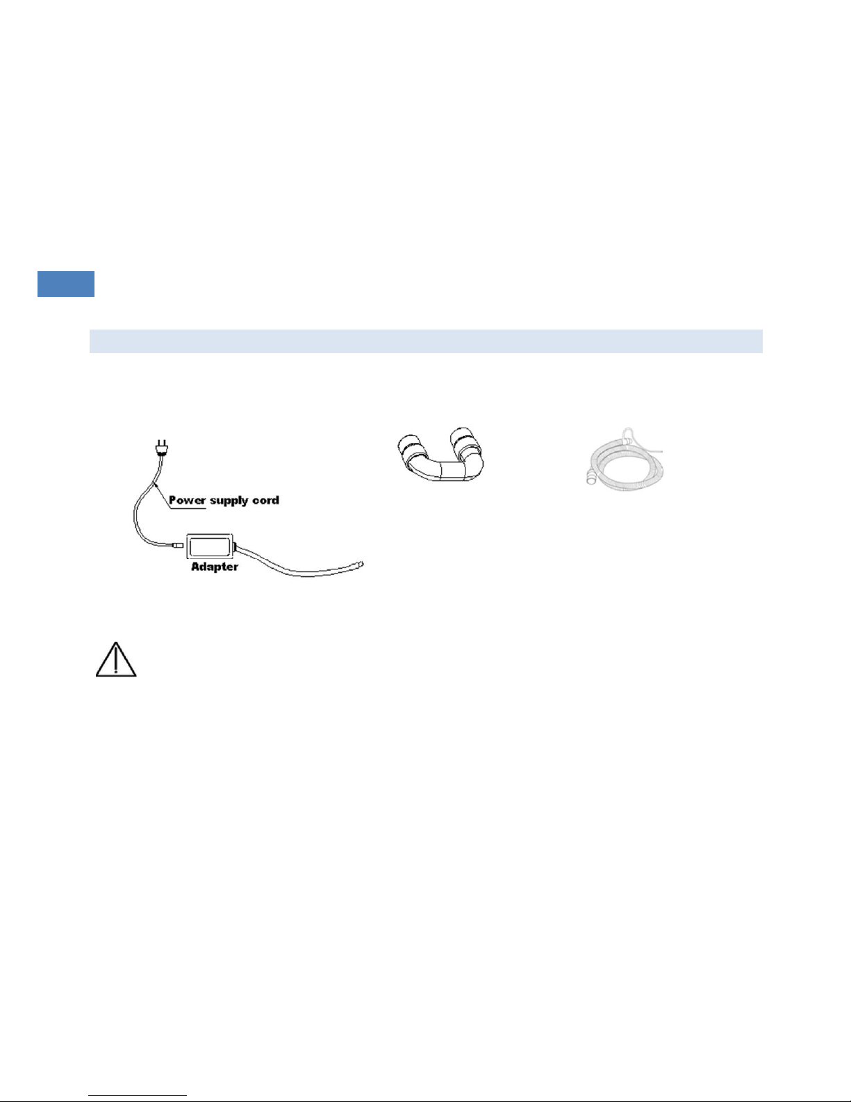
AC CES SOR IES
Power supply cord and power supply adapter
Connecting tube
Hose with a pressure tube
WARNING! The device should be used only with the external AC/DC adapter provided by manufacturer. Use of other
AC/DC adapters may cause damage to the device and cause fire and electric shock hazards.
Page 16

16
Sleep Apnea Breathing Therapy Device
User Manual
16
AC CES SOR IES AND PA RTS
1 Floton ST20 device (including one fine filter)
1 Humidifier
1 Power supply adapter (including one power supply cord for AC input)
1 Hose with an inserted pressure tube
1 Mask (connector diameter 22mm)*
1 Headgear (for use with mask)*
1 Connecting tube
Note: Items with * can be supplied by the manufacturer or purchased from other vendors that are CE-marked.
CONNE CTI NG THE SYS TEM
Check whether the device is damaged and if any accessories or parts are missing.
Put the device on a stable and even surface. Make sure the air inlet in the back of the device is not blocked.
Connect the power supply adapter with the power supply cord and then connect the DC output of adapter with DC power
jack on the back of the device.
Connect the two ends of the hose to the device’s air outlet and mask separately.
Connect the pressure tube to the pressure port in the device.
Connect to the power supply. Power supply adapter: AC input voltage range: AC 100-240V (50/60Hz); DC output: 24VDC2.5A
Max. When the device is on the power indicator light will illuminate and the display will show the preset parameters.
Page 17

17
Sleep Apnea Breathing Therapy Device
User Manual
17
HU MID IFI ER
Before the first use of the Floton ST20 humidifier please clean it thoroughly.
When filling the humidifier with water please disconnect it from the device
Fill the Floton ST20 humidifier with purified or distilled water only. The water must be cool, contain no other additions and
be below the maximum water line.
The temperature range of the humidifier can be adjusted according to patient’s requirement.
When humidifier is connected correctly and the device is turned on and is delivering airflow, the humidifier automatically
heats and the indicator will light green. When it reaches the set temperature the indicator light will switch off. Use the knob
to adjust the heating level.
MA SK
For information on use of the mask please refer to separate instructions provided with the mask.
Page 18

18
Sleep Apnea Breathing Therapy Device
User Manual
18
PA RAM ETE RS, KEYS A ND DIS PLA Y
PA RAM ETE RS
Function
Introduction
Range
IPAP
Inspiratory Positive Air Pressure
4 to 20cmH2O [0.5 cmH2O per step]
EPAP
Expiratory Positive Air Pressure
4 to 20cmH2O [0.5 cmH2O per step]
VT
Tidal Volume
N/A
BPM
Breaths per minute
5 to 40, 1bpm per step
Leak
Leakage Volume per minute
N/A
I-SLOP
Speed of rising pressure
1 to 6, 1 per step
E-SENS
Sensitivity of expiration triggering
1 to 6, 1 per step
MODE
Operation mode
APCV, S, T, ST, CPAP
IE%
The percentage of inspiration time in a respiration cycle,
applicable with T or ST mode
10% to 80% - 1% per step
RAMP
Ramp Time
0 to 60min, 1min per step
AUTO
Automatic operation mode
ON/OFF
Page 19
19
Sleep Apnea Breathing Therapy Device
User Manual
19
KE YS
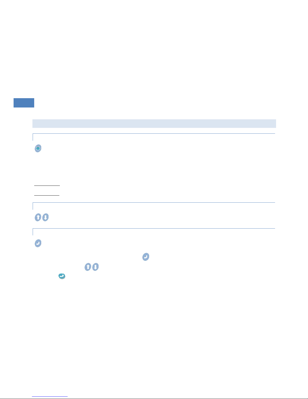
ON /OF F K EY
Press the key down gently for about 1-2 seconds to turn on the device.
When the device is turned on the background light of LCD display will be illuminated. It will be turned off if no any action is
performed within 5 seconds. When the Power supply is plugged in the device is in stand-by mode. The power indicator will be
continuously on when the device is in stand-by mode.
Device On/Off means that motor is On or Off.
Power On/Off means that power supply is On or Off.
IN PUT KEYS
Input keys are used for selecting functions and adjusting the parameters of a given function.
RE TUR N K EY
Return key is used for accessing edit mode and confirming changes of parameters.
To access edit mode to adjust parameters press the key once so that the editing function field blinks.
With the input keys change the value of the selected parameter.
Press key again to confirm and move to next parameter automatically.
Page 20
20
Sleep Apnea Breathing Therapy Device
User Manual
20
DI SPL AY
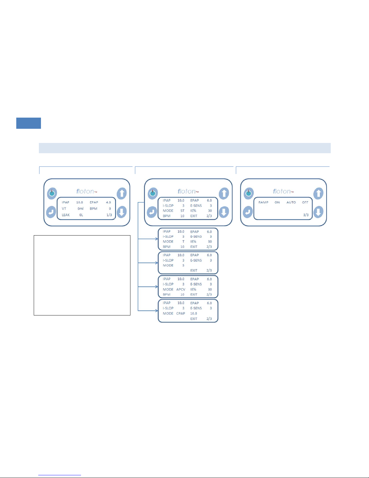
MONIT ORI NG DIS P LAY
MODE DIS PLA Y (S T/T /S/ APC V/C PAP)
RA MP AND AU TO D ISP LAY
Warning! IPAP cannot be set lower than
EPAP.
When CPAP is enabled, then IPAP and
EPAP are limited to 20cmH2O.
Warning! High EPAP pressure could
cause discomfort to the patient.
Carefully evaluate the patient if you set
the EPAP level above 15cmH2O.
Page 21

21
Sleep Apnea Breathing Therapy Device
User Manual
21
FU NCT ION S THE DEV ICE
I- SLO P ( SPEED OF R ISI NG PRE SSUR E)
When Expiration switched to Inspiration, the speed of rising pressure is changeable. The range of the I-SlOP is from 1 to 6, the
smaller of the value, the faster of the pressure rising speed. If I-SlOP is 1, the speed of rising is fastest.
E- SEN S ( SEN SITIVIT Y O F EXPI RATION TRI GGE RIN G)
When the device is working at S mode, the sensitivity of expiration triggering is adjustable. The range of the E_SENS is from 1 to 6,
the smaller of the value, the more sensitive of expiration triggering. If E_SENS is 1, the expiration triggering is most sensitive.
SP ONT ANE OUS MODE: S MOD E
The inspiration and expiration phase is dependent on patient's spontaneous breathing. During the inspiration phase the device
delivers at the preset IPAP pressure and during expiration phase the device delivers at the preset EPAP pressure.
TI MED MO DE : T MOD E
The inspiration and expiration phase is dependent on the settings of the device.The patients breathing will be controlled by the BPM
(Breaths per minute) and IE% (percentage of inspiration time over a respiration cycle) set
The pressure will be switched automatically at a rate determined by BPM and IE%. T Mode only works in manual mode (AUTO OFF).
CP AP MOD E
In CPAP mode the device will output the set pressure constantly.
Page 22

22
Sleep Apnea Breathing Therapy Device
User Manual
22
ST MODE / S PON TAN E OUS-TI MED MO DE
ST mode includes 2 patterns, when the patient is able to breath spontaneously, the device works as S mode; however, when the
patient is unable to breath spontaneously or the patients breath slows to a rate less than the preset backup rate (BPM), the device
will switch to T mode. ST mode works in manual mode (AUTO = OFF).
AU TOM ATI C M ODE
If the device is in Automatic mode the first breath will activate the device when the patient is wearing the mask.
The device will switch to standby mode if:
o The mask is off for 3 seconds or more,
o The patient hose is disconnected, or
o The humidifier is switched off.
PR ESS URE CO NTR OL M ODE: A PCV (A SSI S TED PR ESS URE CO NTROL V EN TILA TIO N)
APCV mode is similar to the ST mode, except that all breaths in a controlled cycle . The APCV mode is a pressure-limited, device-orpatient triggered, time-cycled mode. Therefore, the inspiratory pressure may be triggered by the patient or by the therapy device,
but IPAP will be pressure-limited with a set cycle time determined by the inspiratory time control (IE%)
RA MP FUN CTI ON
When this function is selected the device will start delivering the minimum air pressure first before increasing the pressure steadily
to the set pressure within the set time. This function is to allow the patient to fall asleep more comfortably. This soft start function is
particularly helpful for patients who are not accustomed to continuous positive airway pressure therapy. The pressure delay time
range is between 0 - 60 minutes with pressure steps every minute.
Page 23
23
Sleep Apnea Breathing Therapy Device
User Manual
23
When using Ramp function pressing the On/Off key will activate the Ramp. If the On/Off key is pressed again the Ramp function
will be skipped and the air pressure will rise to the set pressure.
AL ARM S
PO WER FA ILURE
WARNING! During use if a power failure occurs patients may inhale expired air.
In case of a power failure or if the power cord is disconnected the alarm will sound to inform the patient that they should
remove the mask.
The alarm can be switched off by pressing the on/off key or will switch off automatically if power resumes.
CH ECK ING TH E PO WER FA ILU RE ALA RM
Switch the device on and keep running for at least 10 seconds. If the power cord is unplugged or the power is switched off at the
socket the alarm should sound. Check whether the alarm lasts long enough (around 30sec). When the device is switched on the
alarm should stop automatically. Please check the alarm at least once a month.
LEAKA GE
WARNING! To minimize leakage ensure that the headgear is adjusted and fits appropriately
Page 24
24
Sleep Apnea Breathing Therapy Device
User Manual
24
If the AUTO ON function is disabled and the device detects that a patient’s mask has been taken off, or if there is an air leak,
the motor will run at a lower speed automatically and the pressure will reduce to below the set pressure.
When the air leakage stops the device will work normally again and return to the set pressure.
CL EAN ING AN D MAINT ENANCE
CL EAN ING THE F LOT ON ST20
WARNING! To avoid electrical shock unplug the Floton ST20 power cord before cleaning the device
WARNING! Do not immerse the device in liquid or allow any liquid to enter the enclosure, inlet filter, or any other
openings
1. To clean the exterior of the device use a dampened cloth and a mild detergent. Allow the device to dry completely before
plugging in the power cord.
2. The mask and tubing should be cleaned daily. For details on cleaning your mask and accessories refer to the cleaning
instructions packaged with the accessories.
CHANG ING TH E F LOT ON ST2 0 C LOC K BATTE RY
A rechargeable Lithium Button Battery is used for the clock inside the device. There is a danger of explosion and fire if the battery is
incorrectly replaced. Replace only with the same type RTC battery. Model: MC621, 3.0 V, 3 mAh.
CL EAN ING TH E H UMI DIF IER
1. Disconnect the patient hose from the humidifier and remove the upper cap of the humidifier.
2. Empty the water out of the humidifier before cleaning it with a moistened cloth with a mild detergent or soapy water.
3. Never submerge the humidifier in water!
Page 25

25
Sleep Apnea Breathing Therapy Device
User Manual
25
HU MID IFI ER FUS E
The specification of the fuse for the heater in humidifier is 108°C 250V 10A
CHANG ING FI LTER
The fine filter is in the filter cassette at the back of the device. Take it out and change it with a new one every week. Never use the
device without a filter.
Dirty inlet filters may cause high operating temperatures that may affect device performance. Regularly examine the inlet filters for
cleanliness. If there is a lot of dust or smoke in the environment change the filter more frequently.
Page 26
26
Sleep Apnea Breathing Therapy Device
User Manual
26
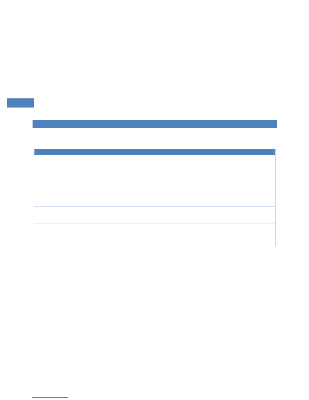
TR OUB LES HOO TIN G
Different problems that may be encountered, their causes and solutions are detailed below.
If your dealer cannot resolve the problems, please consult your physician or contact our service center.
Problem
Cause
Solution
Dryness and irritation of
nose and throat
Dry air
Use a humidifier or heated humidifier
Cold nose
Low room temperature
Increase room temperature
Dryness in mouth and
pharynx
Breathing through mouth
Use chin strap or full face mask
Low therapeutic pressure (ask your
physician)
Irritated or dry eyes
Leakage between mask and skin
Adjust the mask’s position and headgear.
If the mask is worn out, change it. Try
another type of mask.
Redness
or inflammation of skin
under the mask
Headgear is too tight
Wrong mask size
Allergic reaction
Loose the headgear
Ask your physician
Ask your physician
Water in the mask
When the room temperature is low and
the humidifier is on, it may cause water
to condense.
Lower the humidifier’s heating
temperature or increase the room
temperature. Wrap the patient hose in a
towel or a soft cloth to keep warm.
Page 27

27
Sleep Apnea Breathing Therapy Device
User Manual
27
Problem
Cause
Solution
Low output pressure or big
pressure fluctuation
Water getting in the pressure sampling
tube or the pressure tube blocked.
The pressure tube may not be connected
with the device.
Dry thoroughly or clean the pressure
tube.
Connect the pressure tube with the
device correctly.
Pain in nose, sinuses or
ears.
inflammation
Stop therapy and see your physician
immediately.
Discomfort due to high
pressure.
When pressure is over
13cmH2O(~1.3kPa), some patients will
feel unpleasant. But this pressure may
be needed for effective therapy.
You may take up to 4 weeks to be
accustomed to higher pressures. When
using the device, breathe through nose
with mouth closed and keep calm. If you
continue to experience discomfort
consult your physician.
Symptoms of sleep apnea
syndrome appears again.
(like day time sleepiness)
When your weight is increased, your
nose is blocked or you drink etc, you
need higher pressures.
Consult your physician.
Air is too warm
Dirty filter
Air inlet blocked
The device is too close to wall, curtains
or other objects, which hinders air
circulation
Change filter
Check air inlet
Take away the device to keep it over
20cm from wall, curtains or other
objects
No air flow
Defective device
Water in the pressure tube
Contact our service center
Dry the pressure tube thoroughly
Page 28

28
Sleep Apnea Breathing Therapy Device
User Manual
28
Problem
Cause
Solution
Low air flow
Ramp function is active
Air inlet blocked
Decrease soft start time
Check air inlet
Motor always operates at
maximum speed
The pressure tube is not connected or it
is blocked
Leakage in the device
Check the pressure tube
Contact our service center
When turned on, the device
doesn’t work
The device is in automatic operation
(AUTO ON)
Power is not plugged in
No electric supply
Fuse is blown (Note: before checking,
unplug power cable!)
Set the device to manual operation
(AUTO OFF)
Check whether power cable is connected
with the device
Check main electricity supply,
Change fuse
Contact our service center
Motor works normally but
the output pressure is lower
than the set pressure
Patient hose or pressure tube is not
correctly connected with the device
Air leakage through mask or patient tube
Defect device
Check whether connection is correct and
firm
Contact our service center
Only low output pressure
Dirty filter or air outlet blocked
Therapeutic pressure readjusted
Soft start function active
Change filter, check air outlet
Consult your physician
If necessary, cancel soft start function or
set soft start function time again
Too noisy
Patient hose is not connected or
connected incorrectly
Leakage through mask or patient hose
Not air tight between humidifier and
device
Check connection
Check patient hose
Check humidifier and device
Power failure alarm invalid
The device not used for long time (at
least three months)
Put the device on stand-by mode for 12
hours.
Page 29
29
Sleep Apnea Breathing Therapy Device
User Manual
29
SE RVI CE
Service of the Floton ST20 should only be performed by persons authorized by the company.
To increase the device’s life, the user must read the Floton ST20 sleep apnea breathing therapy device’s safety instructions
and cleaning instructions.
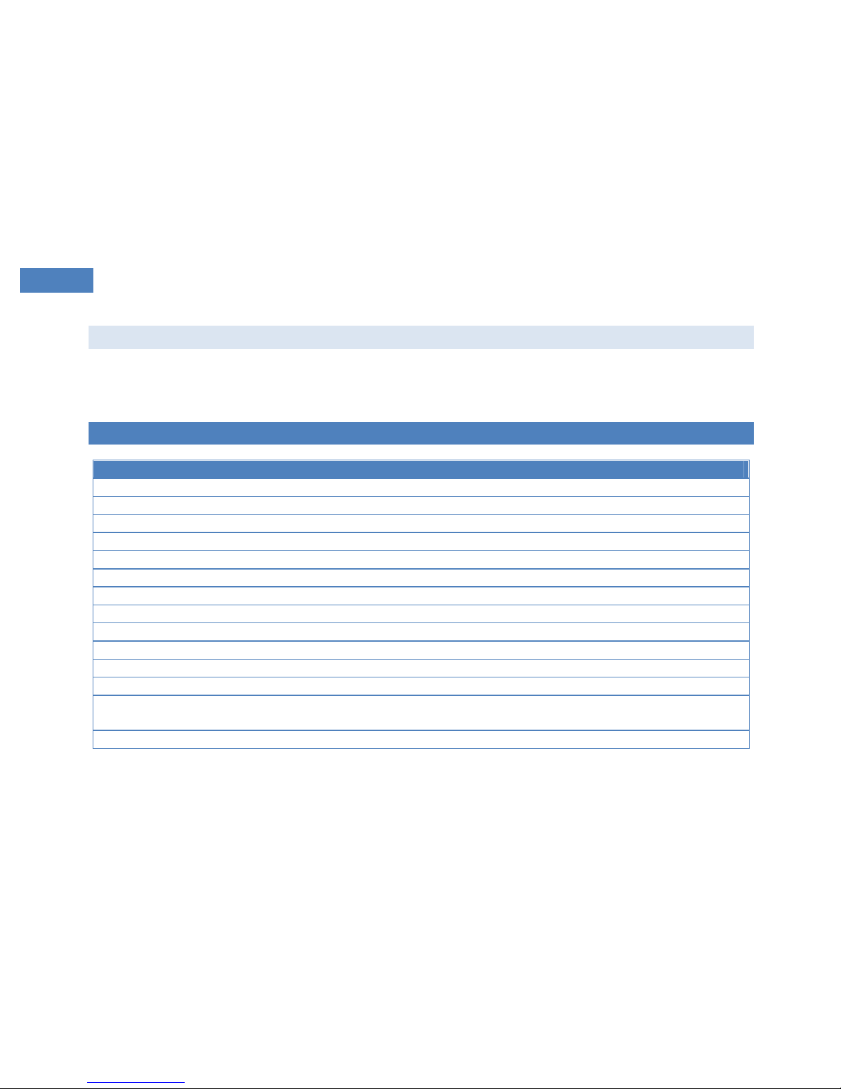
SP ECI FIC ATI ONS
Floton ST20
Pressure range
4cm H2O (~0.4kPa) -20 cm H2O (~2.0kPa)
Pressure variance
±0.4 cm H2O (~0.04kPa)
Ramp time
0-60min. adjustable 1min./step
Noise: (10 cm H2O/~1.0kPa)
<30dB (A)
Dimensions
170 mm L* 117 mmW * 93 mmH
Weight
1.6Kg (1.4Kg without humidifier)
Water temperature
44°C Maximum
DC Voltage
24VDC
DC Current
2.5A Maximum
Protection again electric shock
Class II
Degree of protection against electric shock
Type B Applied Part
Degree of protection against harmful ingress of water
Ordinary Equipment, IPX0
Electromagnetic Compatibility
Floton ST20 sleep apnea breathing therapy device meets the
requirements of EN 60601-1-2.
Fuses
There are no user-replaceable fuses.
Page 30
30
Sleep Apnea Breathing Therapy Device
User Manual
30
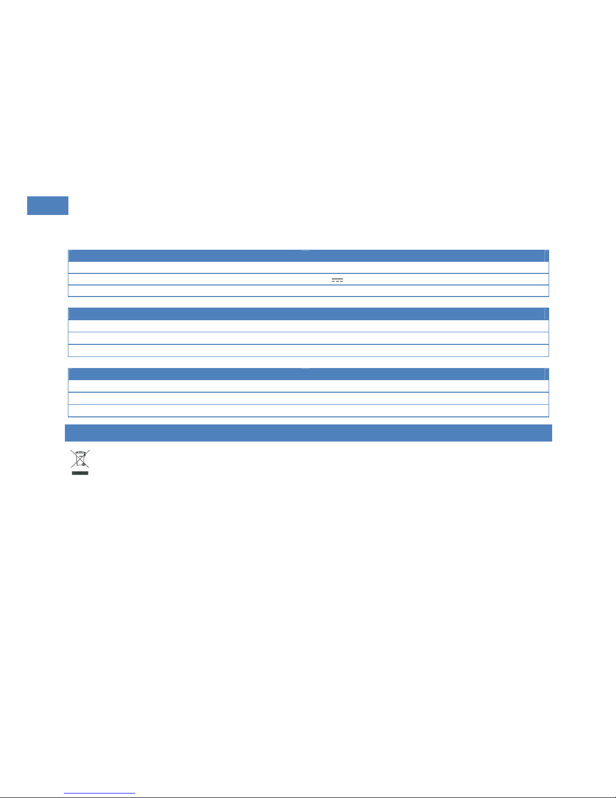
AC/DC adapter
Model
SNP- A069
Output
+24V , 2.5A
Input
100-240V ~, 50/60Hz, 2-1A
Operation
Temperature
+5°C ~ +35°C
Relative humidity
10%%~ 93%(non-condensing)
Atmosphere pressure
700hPa ~ 1060hPa
Transport or storage
Temperature
-20°C ~ +55°C
Relative humidity
10% ~ 93%(non-condensing)
Atmosphere pressure
500hPa ~ 1060hPa
DI SPO SAL
This device, its accessories and its packaging have to be disposed correctly at the end of the usage. Please follow Local Laws or
Regulations for disposal.
Page 31
31
Sleep Apnea Breathing Therapy Device
User Manual
31
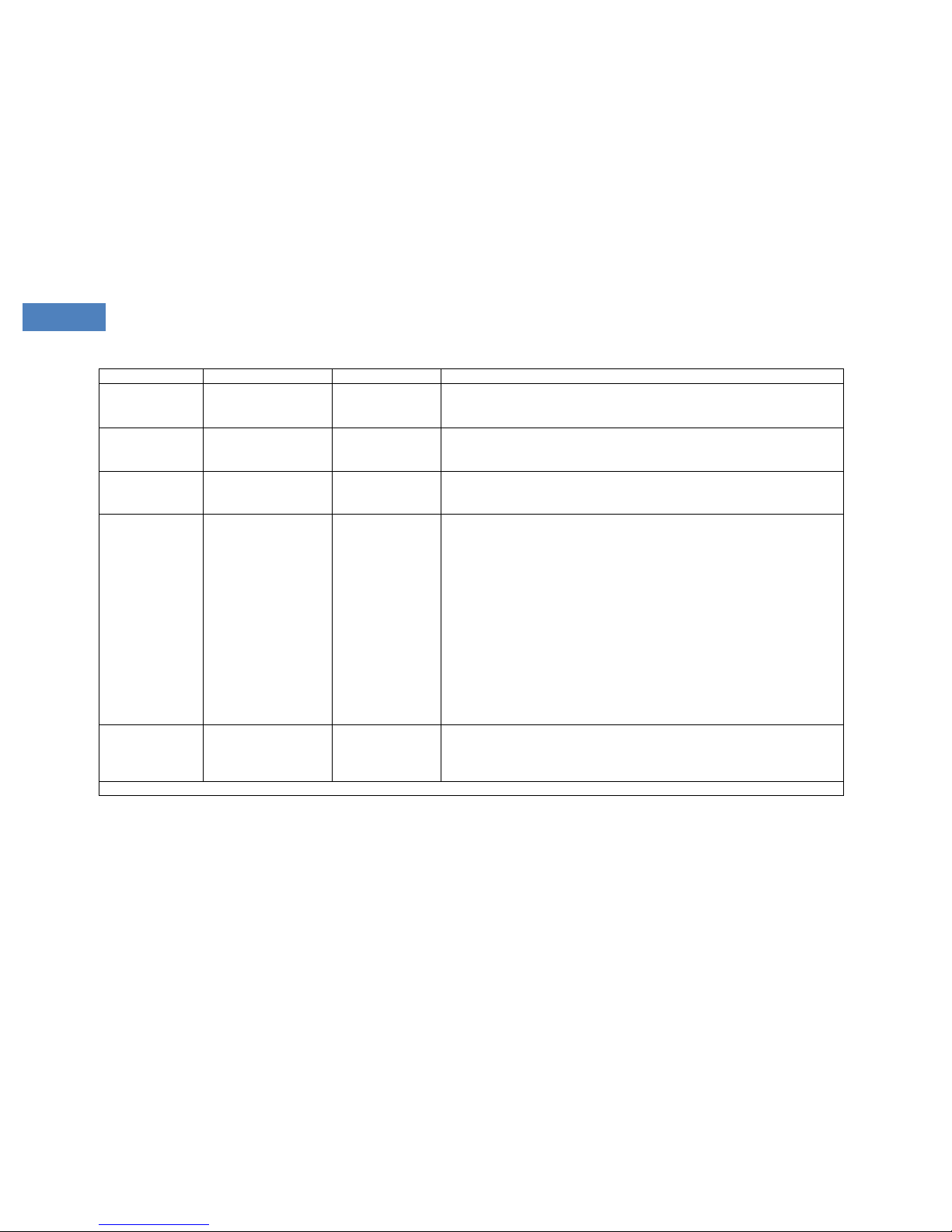
EL ECT RIC MAGN ETI C I NFORM ATI ON
GU IDA NCE AN D MANUF ACT URE RS DEC LAR ATION OF E LEC TRO MAG NETIC I MMU NIT Y F OR EQUIPMENT AN D S YST EMS
TH AT ARE NO T LIFE SUP POR TIN G
Attention! Please use Floton ST20Sleep apnea breathing therapy device according to electric magnetic information in list.
The Floton ST20is intended for use in the electromagnetic environment specified below. The user of the Floton ST20should ensure
that it is used in such an environment.
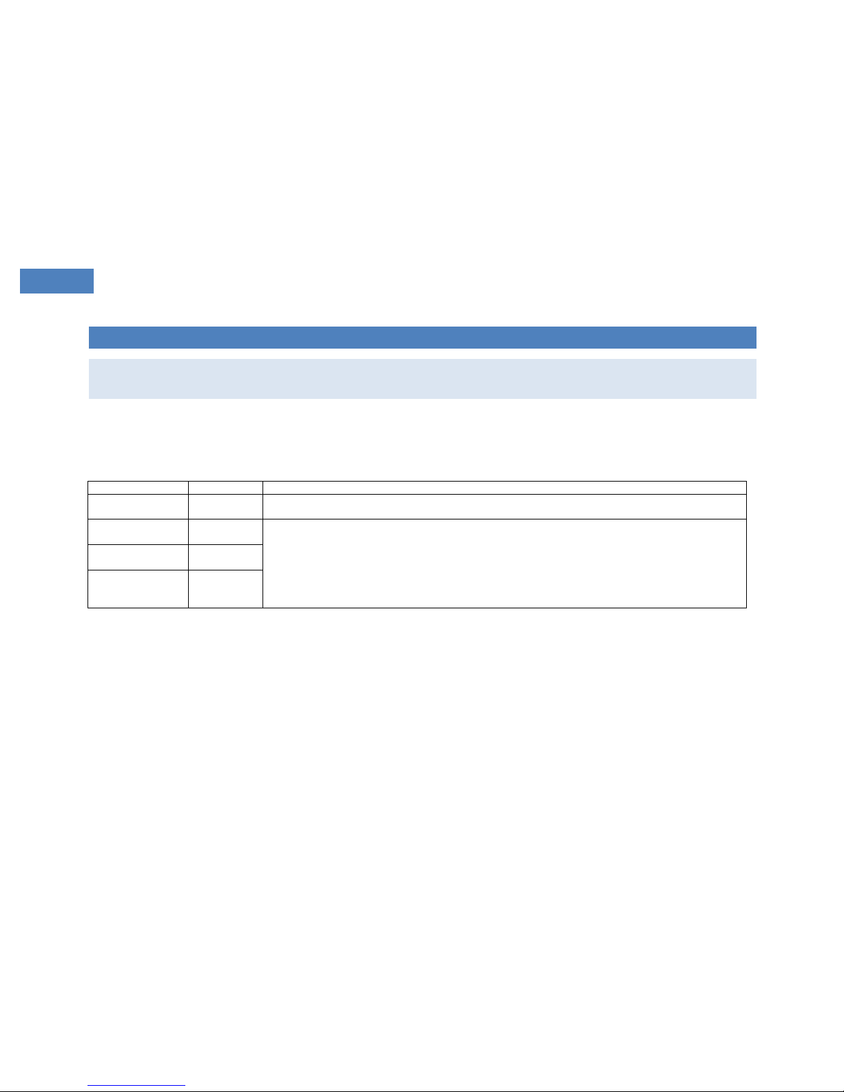
Emission test
Compliance
Electromagnetic environment – guidance
RF emissions
CISPR 11
Group 1
The Floton ST20uses RF energy only for its internal function. Therefore, its RF emissions are very low and are not
likely to cause any interference in nearby electronic equipment.
RF emission
CISPR 11
Class B
The Floton ST20is suitable for use in all establishments, including domestic establishments and those directly
connected to the public low-voltage power supply network that supplies buildings used for domestic purposes.
Harmonic emissions
IEC 61000-3-2
Class A
Voltage fluctuations/
flicker emissions
IEC 61000-3-3
Complies
Page 32
32
Sleep Apnea Breathing Therapy Device
User Manual
32
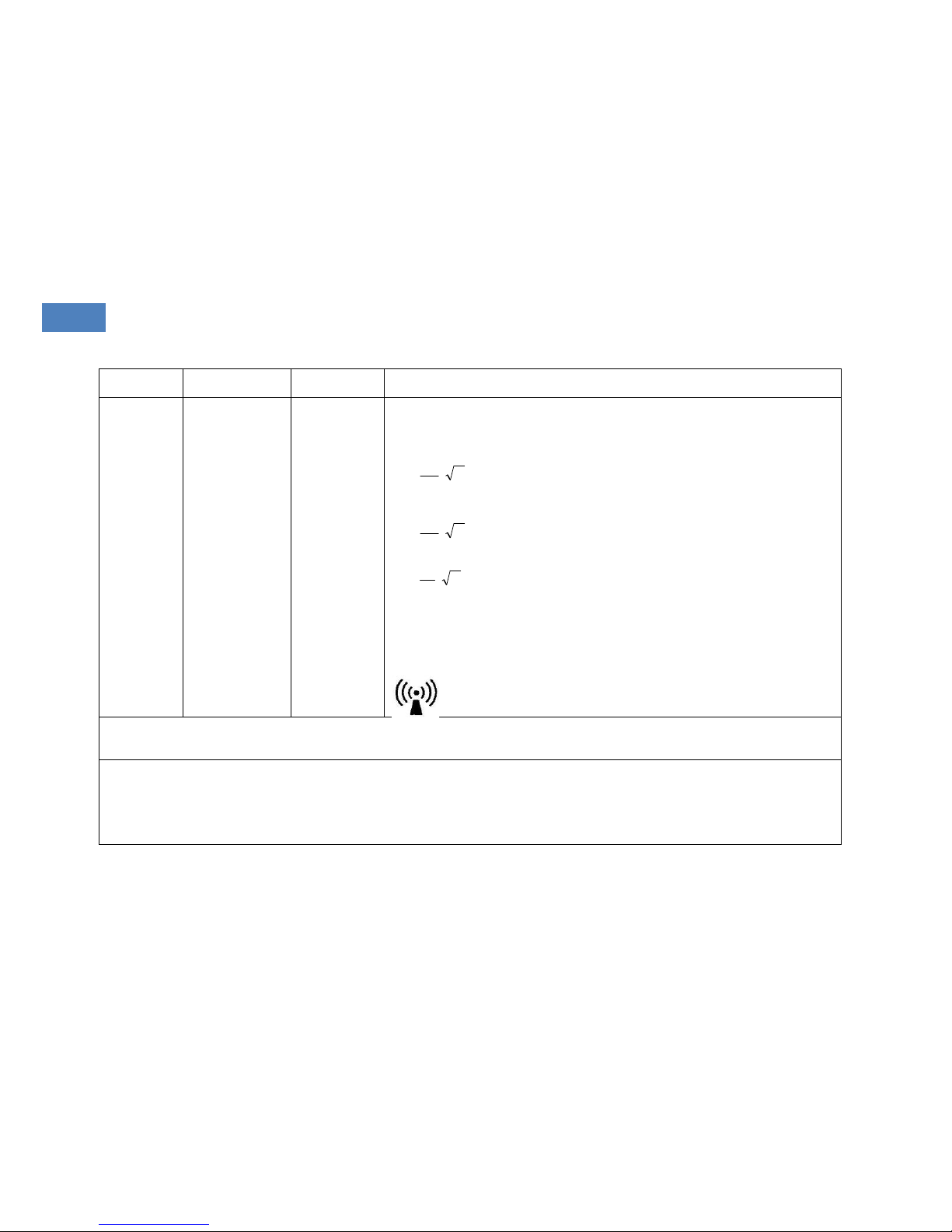
Immunity test
IEC 60601 test level
Compliance level
Electromagnetic environment – guidance
Electrostatic
discharge (ESD)
IEC 61000-4-2
6 kV contact
4 kV air
8 kV air
6 KV contact
4 kV air
Floors should be wood, concrete or ceramic tile. If floor are covered with synthetic
material, the relative humidity should be at least 30%.
Electrical fast
transient/burst
IEC 61000-4-4
2 kV for power supply
lines
2kV for power
supply lines
Mains power quality should be that of a typical commercial or hospital
environment.
Surge
IEC 61000-4-5
1 kV differential mode
1 kV differential
mode
Mains power quality should be that of a typical commercial or hospital
environment.
Voltage dips, short
interruptions and
voltage variations
on power supply
input lines
IEC 61000-4-11
<5% UT
(>95% dip in UT)
for 0.5 cycle
40% UT
(60% dip in UT)
for 5 cycles
70% UT
(30% dip in UT)
for 25 cycles
<5% UT
(>95% dip in UT)
for 5 sec
<5% UT
(>95% dip in UT)
for 0.5 cycle
40% UT
(60% dip in UT)
for 5 cycles
70% UT
(30% dip in UT)
for 25 cycles
<5% UT
(>95% dip in UT)
for 5 sec
Mains power quality should be that of a typical commercial or hospital
environment. If the user of the Floton ST20requires continued operation during
power mains interruptions, it is recommended that the Floton ST20be powered
from an uninterruptible power supply or a battery.
Power frequency
(50/60Hz)
Magnetic field
IEC-61000-4-8
3 A/m
3 A/m
Power frequency magnetic fields should be at normal levels typical of a location in
a commercial or hospital environment.
NOTE: UT is the A/C mains voltage prior to application of the test level.
Page 33
33
Sleep Apnea Breathing Therapy Device
User Manual
33
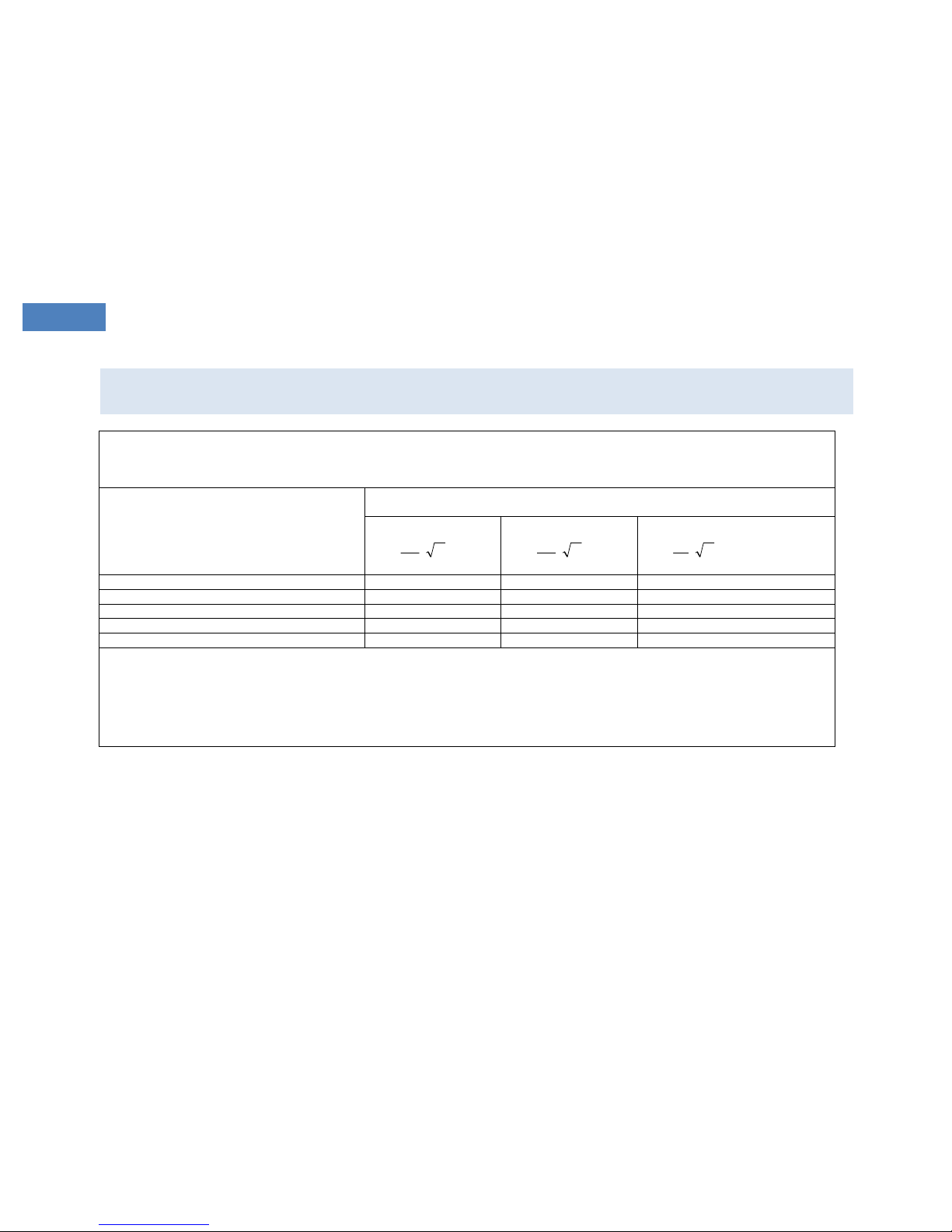
Immunity test
IEC 60601 test level
Compliance
level
Electromagnetic environment – guidance
Conducted RF
IEC 61000-4-6
Radiated RF
IEC 61000-4-3
3 Vrms
150 kHz to 80 MHz
3 V/m
80 MHz to 2.5 GHz
3 Vrms
3 V/m
Portable and mobile RF communications equipment including cables should not be used close
to any part of the Floton ST20other than the recommended separation distance calculated
from the equation applicable to the frequency of the transmitter.
Recommended separation distance
P
V
d
1
5.3
P
E
d
1
5.3
80 MHz to 800 MHz
P
E
d
1
7
800 MHz to 2.5 GHz
Where P is the maximum output power rating of the transmitter in watts (W) according to the
transmitter manufacturer and d is the recommended separation distance in metres (m).
Field strengths from fixed RF transmitters, as determined by an electromagnetic site survey,a
should be less than the compliance level in each frequency range.b
Interference may occur in the vicinity of equipment marked with the following symbol:
NOTE 1: At 80 MHz and 800 MHz, the higher frequency range applies.
NOTE 2: These guidelines may not apply in all situations. Electromagnetic propagation is affected by absorption and reflection from structures, objects and
people.
Field strengths from fixed transmitters, such as base stations for radio (cellular/cordless) telephones and land mobile radios, amateur radio, AM and FM
radio broadcast and TV broadcast cannot be predicted theoretically with accuracy. To assess the electromagnetic environment due to fixed RF transmitters,
an electromagnetic site survey should be considered. If the measured field strength in the location where the Floton ST20is used exceeds the applicable RF
compliance level above, the Floton ST20should be observed to verify normal operation. If abnormal performance is observed additional measures may be
necessary, such as, re-adjusting or relocating the Floton Auto CPAP.
b Over the frequency range 150 kHz to 80 MHz, field strengths should be less than 3 V/m.
Page 34
34
Sleep Apnea Breathing Therapy Device
User Manual
34
RE COM MEN DED SEPARA TIO N D IST ANC ES B ETW EEN P ORTABL E AN D M OBI LE RF COM MUN ICA TIO NS E QUI PMENT AND
TH E F LOT ON AUTO CP AP
The Floton ST20is intended for use in an electromagnetic environment in which radiated RF disturbances are controlled.
The customer or the user of the Floton ST20can help prevent electromagnetic interference by maintaining a minimum distance between portable and
mobile RF communications equipment (transmitters) and the Floton ST20as recommended below, according to the maximum output power of the
communications equipment
Rated maximum output power of transmitter
(W)
Separation distance according to the frequency of transmitter
(m)
150 kHz to 80 MHz
P
V
d
1
5.3
80 MHz to 800 MHz
P
E
d
1
5.3
800 MHz to 2.5 GHz
P
E
d
1
7
0.01
0.12
0.12
0.23
0.1
0.39
0.37
0.74
1
1.17
1.17
2.33
10
3.69
3.69
7.38
100
11.67
11.67
23.33
For transmitters rated at a maximum output power not listed above, the recommended separation distance d in metres (m) can be estimated using the
equation applicable to the frequency of the transmitter, where P is the maximum output power rating of the transmitter in watts (W) according to the
transmitter manufacturer.
NOTE 1: At 80 MHz and 800 MHz, the separation distance for the higher frequency range applies.
NOTE 2: These guidelines may not apply in all situations. Electromagnetic propagation is affected by absorption and reflection from structures, objects and
people.
Page 35

35
Sleep Apnea Breathing Therapy Device
User Manual
35
CONTA CT DETAILS
Curative Medical Devices GmbH
Manufacturer address: Blasewitzer Str. 41, 01307 Dresden, Germany
Tel: +49-351-4504500
Fax: +49-351-4504511
 Loading...