

1
Cuppone Pizzaform
User and Installation Manual
Note: Pizza Equipment Professionals has provided this
manual as an English only copy of the Cuppone F. LLI SRL
Manual provided by the manufacturer. Words and
Descriptions may have been altered. If you have questions
please reference the Manufacturer’s Manual you have
received with your purchase.
www.PizzaEquipmentPros.com 800.655.1831 17981 S. Ideal Parkway. Manteca, CA. 95336. U.S.A. info@PizzaEquipmentPros.com

2
INDEX
Introduction
Initial Instructions
Explanation of Symbols
Risk Analysis
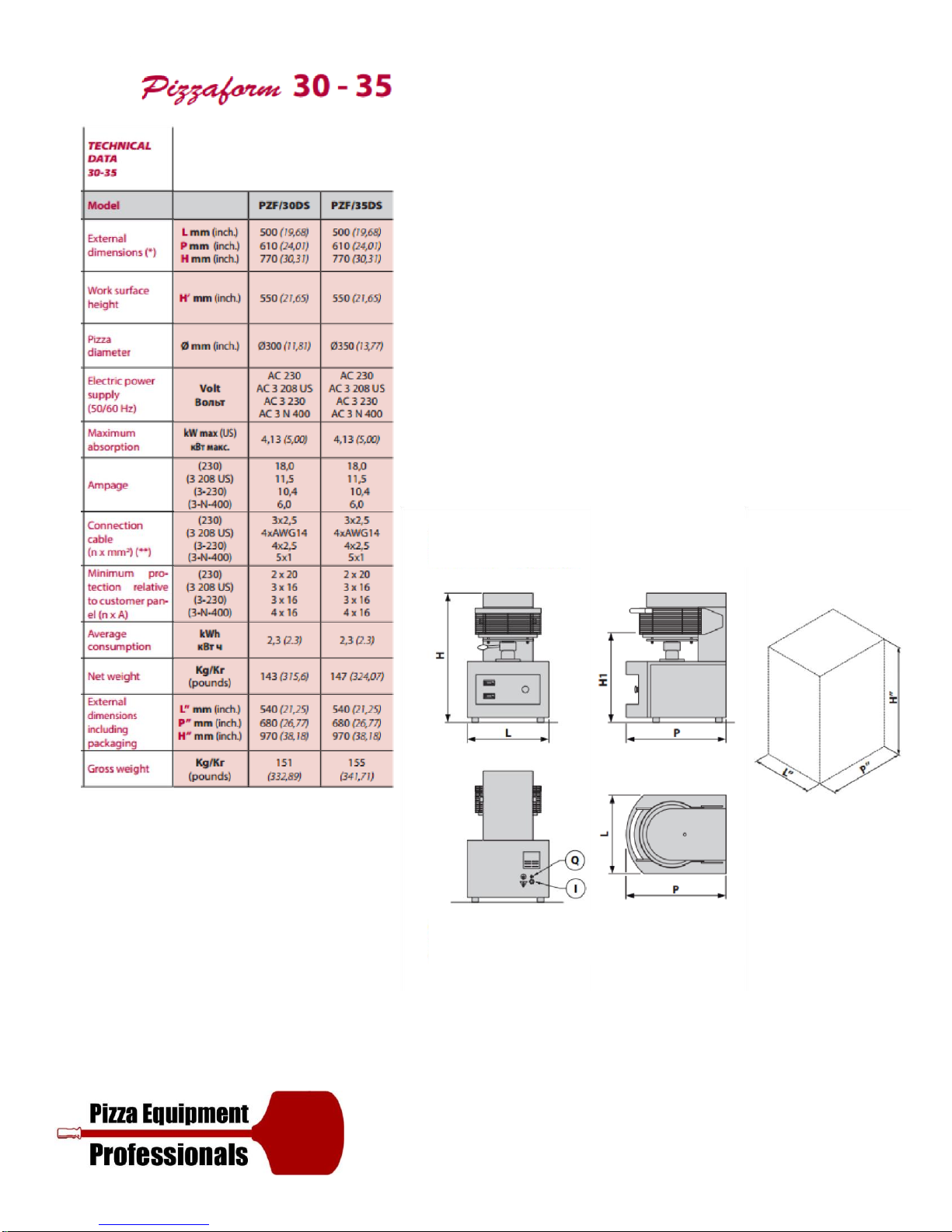
Technical Data (Pizzaform 30, 35)
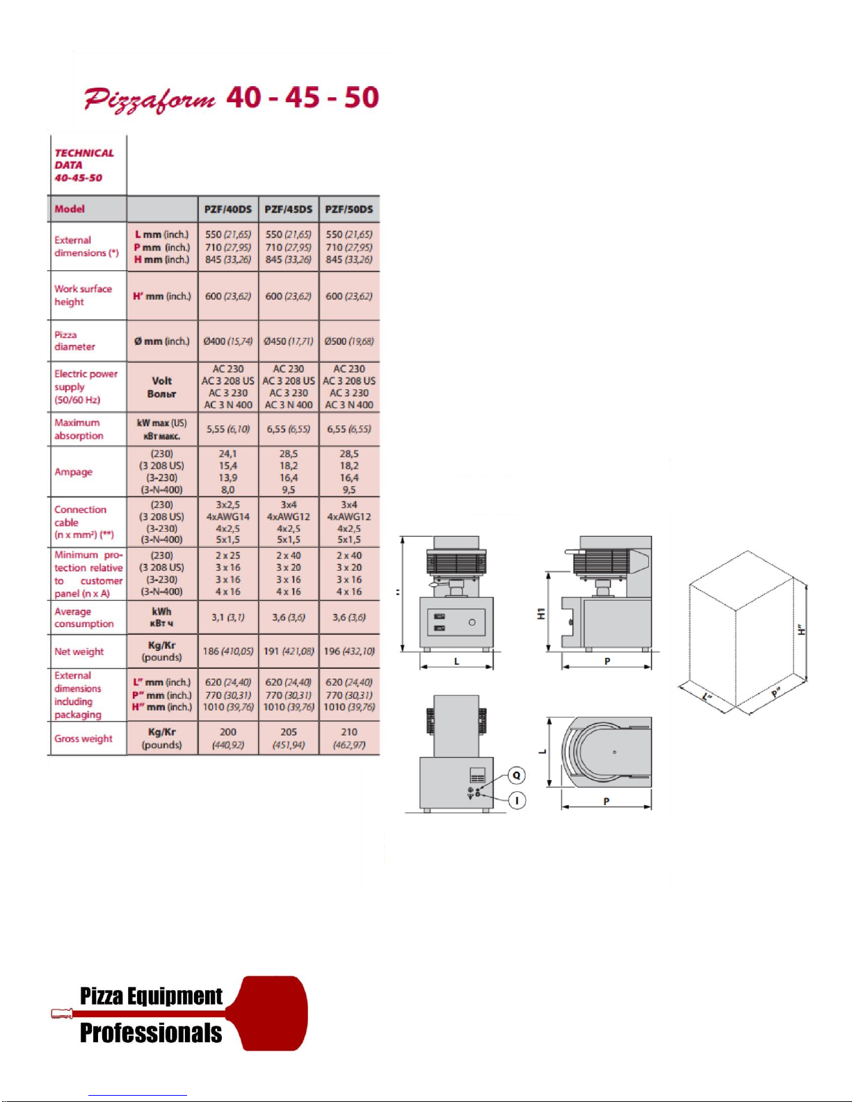
Technical Data (Pizzaform 40, 45, 50)
General Specifications
Installation Requirements
Safety Distances
Instructions for the Installer
Uploading & Transport
Preparations and Checks
Positioning
Electrical Connections
Power Supply, Activation, Operation Verification
Pre-test
Control Panel Description
Instructions for the User
Turning On
Setting the Plate Temperature
Setting the Plate Contact Time (Dwell Setting)
Use
Shutting OFF
Countdown Function
Strike Counting Function
Troubleshooting
Recommendations Governing Use
Maintenance Instructions
Maintenance
Positioning of Main Controls
Wiring Diagram
Warranty Conditions
Limits
Exclusions

3
INTRODUCTION
The present manual refers to various electronic control PIZZAFORM pizza hot forming machine models.
The present manual was originally written in Italian. All other languages are translations.
Congratulations on selecting a product that was designed and constructed with advanced technology.
We recommend that you read through this manual fully before using this equipment. It contains very
important information and instructions regarding installation, use and maintenance.
The equipment you have purchased was carefully designed and constructed and has been subjected to strict
inspection tests in our laboratories, therefore we can guarantee its absolute safety and functionality.
Installation must be done according to the instructions by professionally qualified personnel who are able to
take on the responsibility for the installation and guarantee the best conditions for operation and safety.
TECHNICAL SUPPORT
The manufacturer is able to solve any technical problem concerning use and maintenance. In the remote
possibility of poor operation or a repair, only use qualified personnel or contact our authorized service
centers.
INITIAL INSTRUCTIONS
ATTENTION! Failure to comply with what is described in this handbook could jeopardize safety.
The manual must be kept carefully in an accessible location, it must also always accompany the product
during its life.
Before installing and using the equipment, this manual must be read carefully and the instructions it contains
must be followed scrupulously.
The manufacturer declines all civil and criminal liability for damage to people, property or animals deriving
from the failure to observe current safety regulations, failure to respect the contents of this manual and
from any printing or transcription errors.
It also declares that it reserves the right to make any changes to the product that it considers appropriate
without the obligation to provide notice.
Before handling, installing, or using the product, verify the suitability of the room where it will be located.
Make sure that all safety measures have been taken in order to avoid any accidents.
4
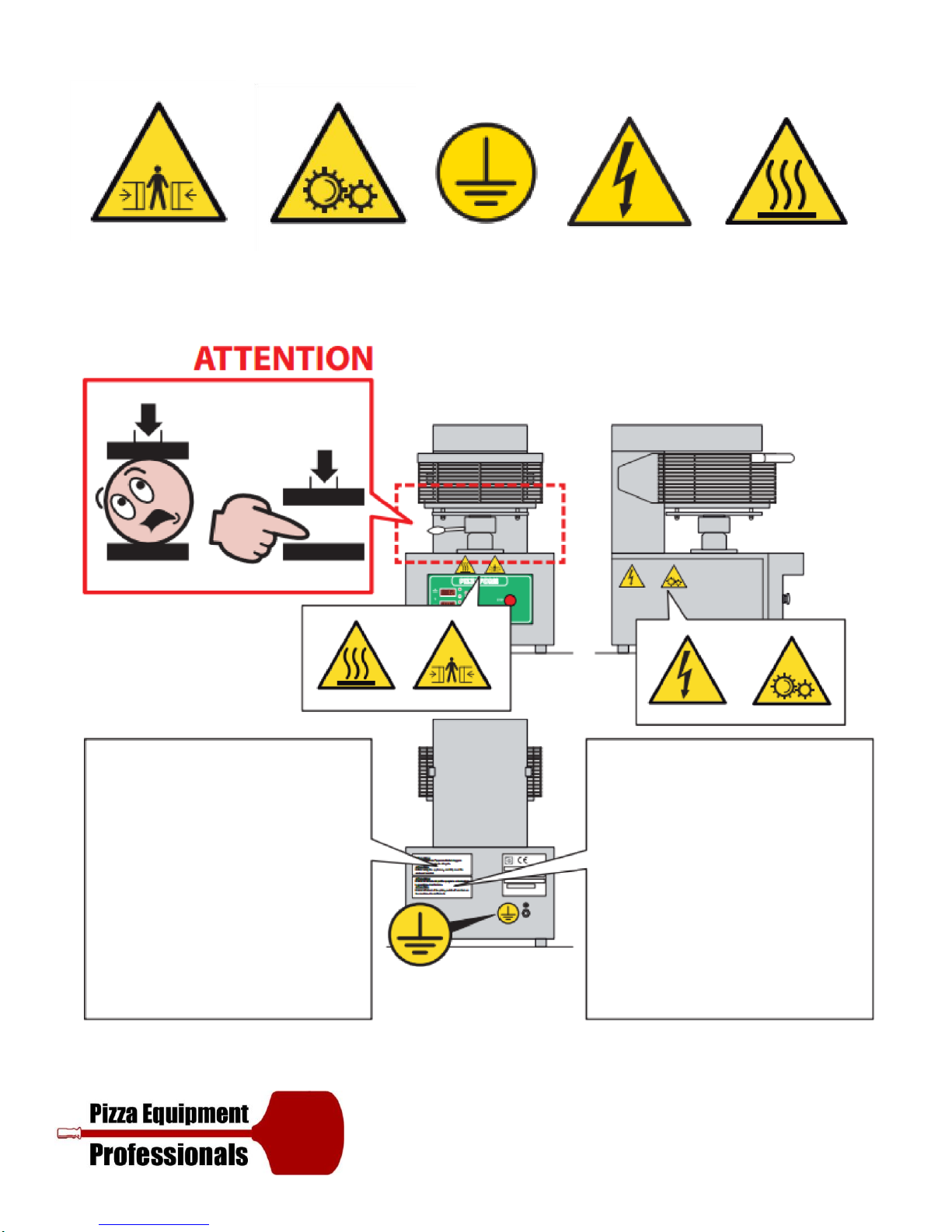
EXPLANATION OF SYMBOLS
Risk of Crushing Fingers
Equipotential
Risk of Electric
Shock
Risk of Blistering
Surface
Warning: Before using
the equipment
carefully read the
enclosed booklet.
Warning Gear
Wheels
Warning: In case of
arrest of the plate,
switch off and turn on
the machine. Do not
force it.
5
RISK ANALYSIS
The machine was designed in compliance with the Machinery Directive 2006/42/EC and Legislative Decree
no. 17 of the 27 January 2010.
In compliance with these standards an assessment of the possible damage resulting from risks to health and
the safety of operators of the machines in question, should a hazed come to light, was carried out.
According to the analysis there are outstanding risks associated with the use of the machine which cannot be
eliminated without loss of machine functionality and without increased cost.
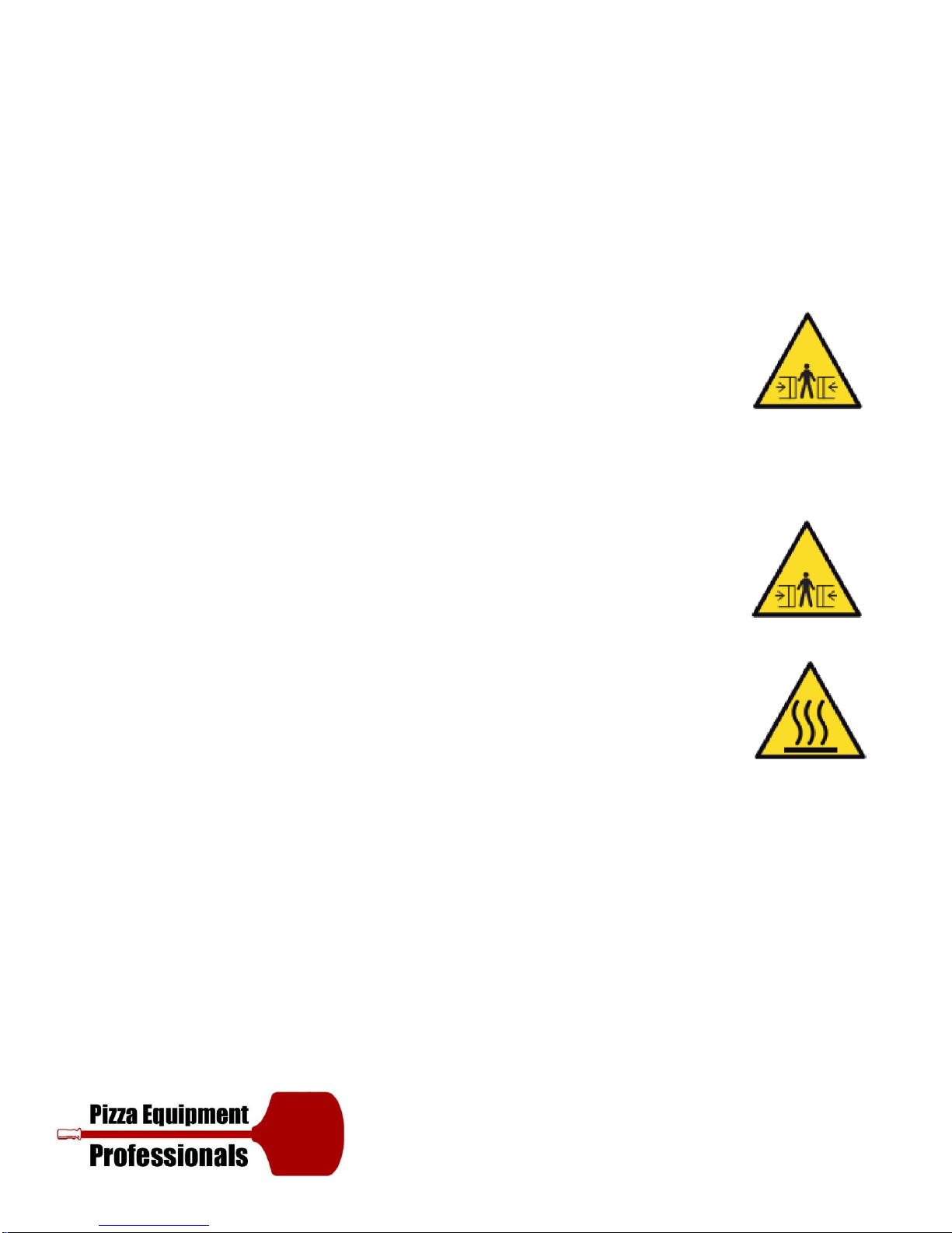
These outstanding risks include:
The operators head may get crushed by the plates upon opening. The outstanding
risk is signaled by the pictogram on the machine.
Risk of breakage and projection of objects during insertion of the blade into the
protections during closure. Do not insert any objects into the protection grille when the machine is
moving, not even to unblock the plates.
In the case where the machine is blocked, switch it off and then on again.
Risk of crushing fingers at the plate piston base. The piston base is flared to enable
sliding of the fingers and to prevent catching; an outstanding risk of crushing of the
fingers where forced into position, remains.
Do not attempt to access or intervene at the piston base where the machine is moving.
The outstanding risk is signaled by the pictogram on the machine.
Risk of burns when touching the plates: during use, the surfaces of plates become hot,
we recommend taking extra caution. The outstanding risk is signaled by this pictogram.
6
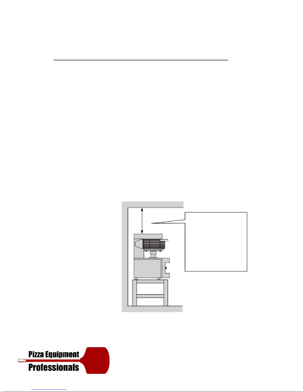
Ensure that you keep a distance of at least 500 mm
(20
inches) between the equipment and other
equipment of inflammable materials.
We advise that you leave an unrestricted space of
at least 500 mm to the right side to allow for easy
access to the electrical system.
Leave the space above the equipment free: do not
place anything on it.
L: width P: depth H: height
Front View
Side View
Packaging
Dimensions
These cables can only be used provided
that their length does not exceed 2 m
between the point where the cable or
relative protection enters the equipment
and the plug input.
Plain View
Rear View
7
Front View
Side View
Packaging
Dimensions
Ensure that you keep a distance of at least 500 mm
(20
inches) between the equipment and other
equipment of inflammable materials.
We advise that you leave an unrestricted space of
at least 500 mm to the right side to allow for easy
access to the electrical system.
Leave the space above the equipment free: do not
place anything on it.
L: width P: depth H: height
These cables can only be used provided
that their length does not exceed 2 m
between the point where the cable or
relative protection enters the equipment
and the plug input.
Plain View
Rear View
8
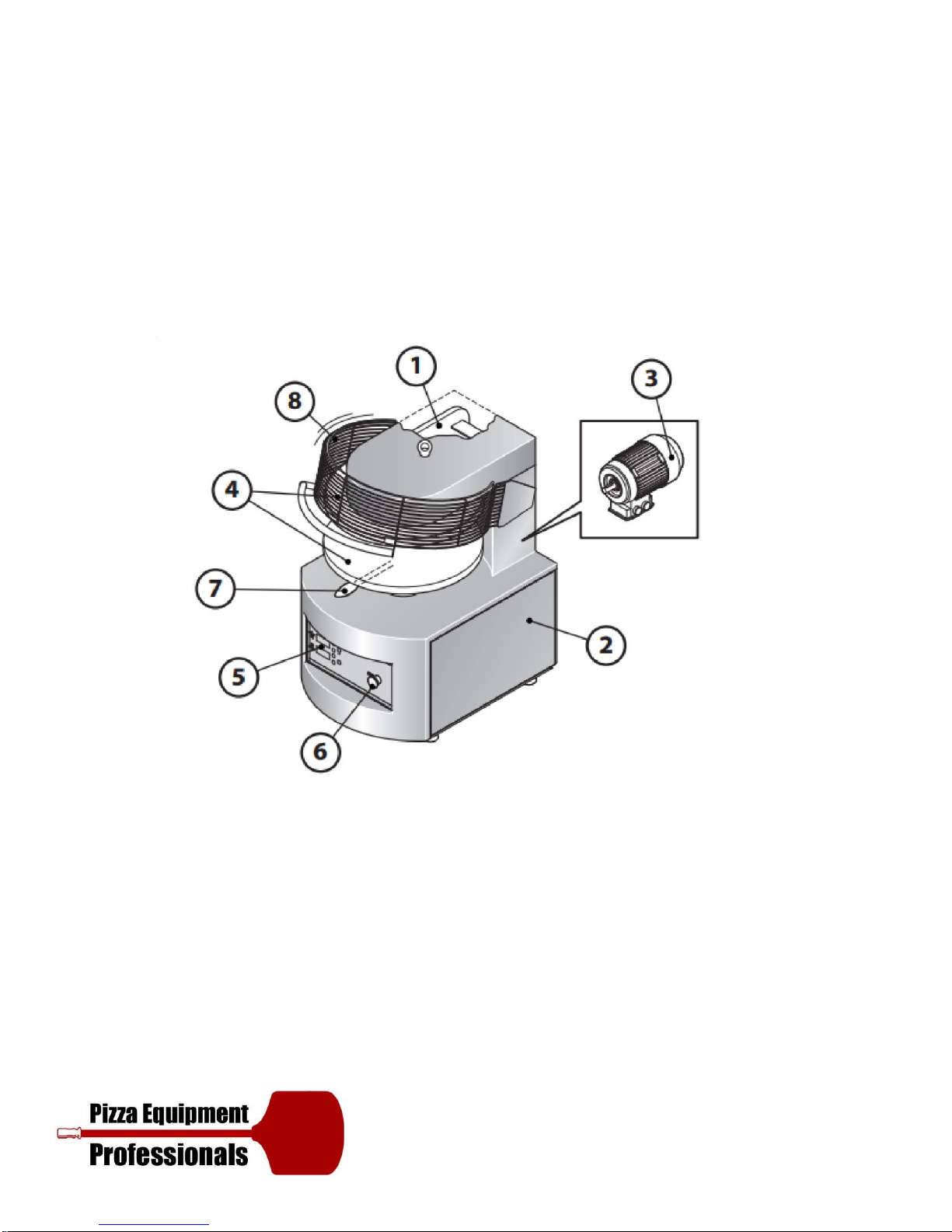
GENERAL SPECIFICATIONS
1 Iron supporting frame with thickness of 20 mm.
2 Stainless steel body
3 Self-braking motor (direct-current brake) with built-in thermal protection.
4 Thick chromed plates with flared perimeter.
5 Electronic control of temperature and plate contact time.
6 EC certified safety devices.
7 Lever to adjust the distance between plates.
8 Protection grille.
To access the specifications explicit to your model, consult the technical data table above.
9
INSTALLATION REQUIREMENTS
Before starting the installation, check the following conditions that are necessary for proper equipment
operation and maintenance:
1) Handling: Make sure that the floor is able to support the weight of the equipment. Handle the packaged
equipment using a forklift or a pallet truck.
2) Electrical connection: Provide a box for the connection to the mains power supply in the immediate
surroundings.
3) Safety distances: It is mandatory that the minimum safety distances between the equipment and the
other equipment or inflammable material are respected (see page 20).
It is also prohibited to use the equipment in areas at risk of explosion. The indicated distances must be
increased in the presence of heat sensitive material.
SAFETY DISTANCES
It is mandatory that the minimum safety distances between the equipment and the other equipment or
inflammable material are respected (see page 20).
It is also prohibited to use the equipment in areas at risk of explosion. The indicated distances must be
increased in the presence of heat sensitive material.
Leave this area
unobstructed
 Loading...