

Cuno CFSUV-5, CFSUV-5-2 Installation And Operating Instructions Manual
For CUNO®Food Service CFSUV-5 and CFSUV-5-2
INSTR4200 0304
Installation and
Operating Instructions
New Electronic ICE Ballast
This UV system contains a patented electronic ICE ballast. It is designed to provide constant UV output over a
wide range of input voltages or frequencies.
Warning: The light given off by this unit can cause serious burns to unprotected eyes and skin. Never look
directly at a burning UV lamp. When performing any work on the UV sterilizer always unplug the unit first.
Never operate the UV system while the UV lamp is outside of the UV chamber.
Note: The UV lamp inside of the sterilizer is rated at an effective life of approximately 9,000 hours. To ensure
continuous protection, replace the UV lamp annually.

1
Safety Instructions
Warning: To guard against injury, basic safety precautions should be observed, including the following:
1. READ AND FOLLOW ALL SAFETY INSTRUCTIONS.
2. DANGER: To avoid possible electrical shock, special care should be taken since water is present near electrical
equipment. Unless a situation is encountered that is explicitly addressed by the provided maintenance and troubleshooting sections, do not attempt repairs yourself. Contact CUNO Food Service Authorized Distributor for service.
3. Carefully examine the UV system after installation. It should not be plugged in if there is water on parts not
intended to be wet.
4. Do not operate the UV system if it has a damaged cord or plug, if it is malfunctioning or if it is dropped or
damaged in any manner.
5. Always disconnect water flow and unplug the UV system before performing cleaning or maintenance activities.
Never yank the cord to remove from an outlet; grasp the wall plug and pull to disconnect.
6. Do not use this UV system for other than intended use (potable water applications). The use of attachments not
approved, recommended or sold by the manufacturer or distributor may cause an unsafe condition.
7. Intended for indoor use only. Do not install this UV system where it will be exposed to the weather or to temperatures
below freezing. Do not store this UV system where it will be exposed to temperatures below freezing unless all water
has been drained from it and the water supply has been disconnected.
8. Read and observe all the important notices and warnings on the UV system.
9. If an extension cord is necessary, a cord with a proper rating should be used. A cord rated for less amperes or
watts than the UV system rating may overheat and create a fire hazard. Care should be taken to arrange the cord
so that it will not be damaged, tripped over or pulled.
10. SAVE THESE INSTRUCTIONS.
Water Chemistry
Water quality is extremely important for the optimum performance of the UV system. The following levels are recommended for installation:
• TOTAL IRON count is less than 0.3 ppm (mg/l)
• HYDROGEN SULFIDE count is less than 0.05 ppm (mg/l)
• SUSPENDED SOLIDS count is less than 10 ppm (mg/l)
• MANGANESE count is less than 0.05 ppm (mg/l)
• HARDNESS count is less than 7 gpg (where total hardness is less than 7 gpg, the UV system should operate
efficiently provided the quartz sleeve and/or sensor probe is cleaned periodically)
If the water chemistry contains levels in excess of those mentioned above, proper treatment is recommended to correct
these water problems prior to the installation of the UV system. Consult a CUNO Food Service Authorized Distributor for
pretreatment recommendations.
Before Installing the System
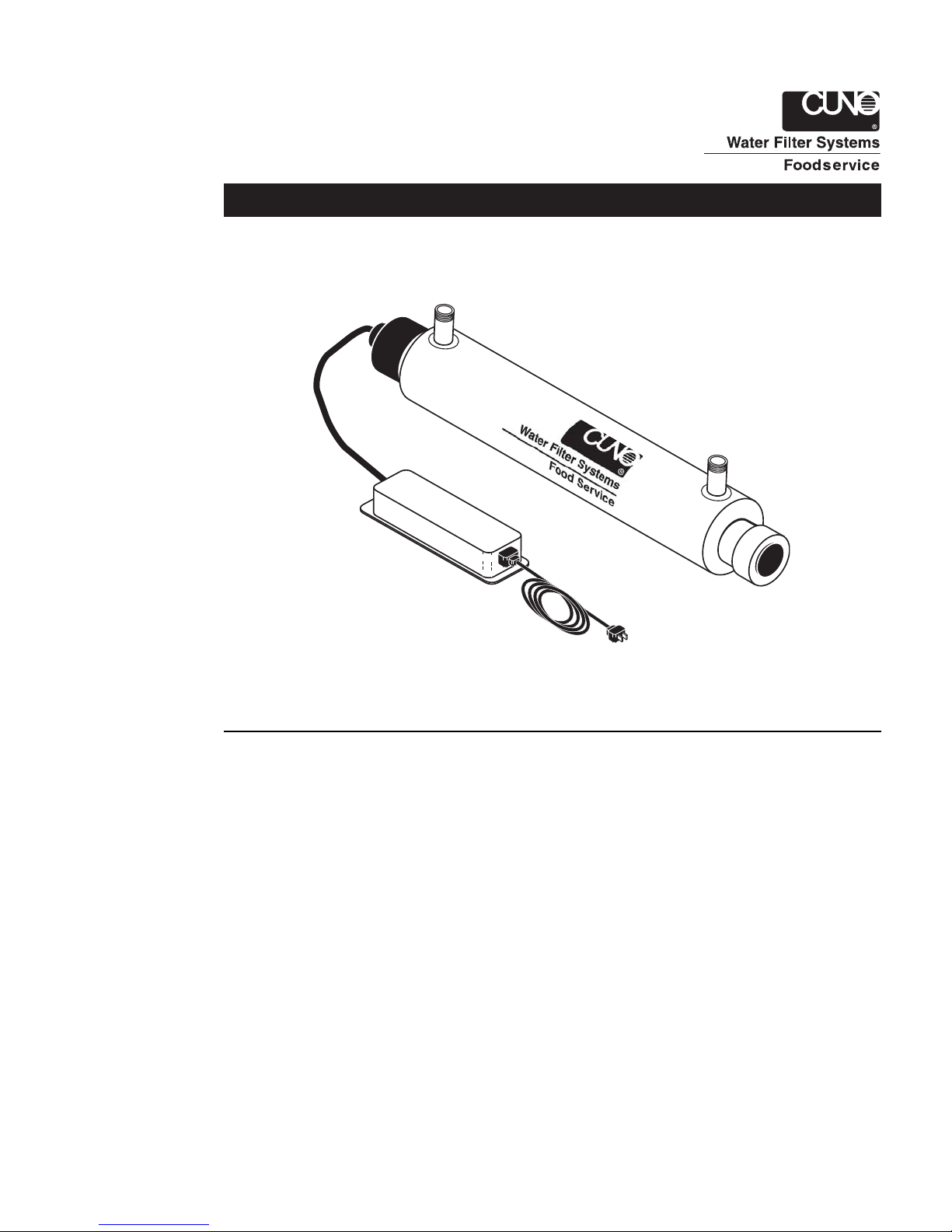
The CUNO Food Service UV system is packaged as follows:
• Stainless Steel Reactor Chamber
• UV Lamp with Quartz Sleeve
• Patented Electronic ICE Ballast
NOTE: A minimum of a 5 micron sediment filter (not included) must precede the UV system.
NOTE: For cold water use only.
NOTE: For potable water use only.

2
Installing the UV System
CAUTION:
• The UV system must be connected to a ground fault interruptor.
• The electronic ballast should be mounted either above or beside the reactor chamber. This will prevent moisture
caused by condensation from entering the ballast enclosure, a potential for ballast failure and electrical shock hazard.
• The UV system must be installed within 5 ft (1.5 m) of an electrical outlet.
• The electronic ballast must be connected to a grounded receptacle and the lamp connector ground wire connected
to the reactor chamber.
• The complete water system, including any pressure or hot water tanks, must be sanitized before the start-up of
the UV system to destroy any residual contamination.
Installation
Note: The reactor chamber should be mounted in the vertical position with the lamp connector on top. The water flow
must enter from the bottom port and exit from the top port to ensure optimum operating efficiency. If the chamber cannot be mounted vertically, horizontal mounting should only be done with the ports facing up. Leave enough space to
allow for the removal of the UV lamp and/or quartz sleeve (typically leave a space equal to the size of the system itself).
1. Remove the UV system from the shipping carton. For shipping purposes, the UV lamp is packed in a separate
cardboard tube. Carefully remove the UV lamp from the tube, being careful to handle by the ends only. Remove
the plastic end cover. Do not touch the glass itself.
2. Insert the UV lamp into the quartz sleeve, making sure the connection end is inserted last and centering spring is
inside of quartz sleeve. Affix the lamp connector to the UV lamp pins, press-fit into the aluminum gland nut, and
replace the plastic end cover.
3. Mount the reactor chamber to the wall with the supplied clamp(s). Mount the electrical ballast to the wall either
above or beside the reactor chamber.
4. Various connection methods can be used to connect the water source to the UV system, however union type
connectors are recommended. The use of a flow restrictor device is strongly recommended when installing the
UV system in order that the manufacturers recommended flow rate is not exceeded. In addition, the use of a
bypass assembly is recommended for emergency use of untreated water when the UV system is being serviced.
NOTE: When the UV system is returned to service after being on bypass, the complete water system must be
sanitized once again to destroy any contamination that may have entered the distribution system while on
bypass. DO NOT SOLDER CONNECTIONS WHILE ATTACHED TO THE UV SYSTEM AS THIS COULD DAMAGE THE
O-RING SEALS.
5. Prior to connecting to the power source outlet, check all connections to ensure that they are secure, slowly turn
on the water supply, and check for leaks. The most likely cause for leaks is from the o-ring seal. In case of a leak,
shut off water, drain the cell, remove the retainer nut, wipe the o-ring and threads clean, and reinstall.
6. Once it is determined that there are no leaks, ground the reactor chamber. To do so, attach the green wire
coming from the electronic ballast to the grounding lug on the reactor chamber. Remove the green cap nut and
slide the eyelet connector onto the screw. Fasten the cap nut to the screw with a 5/16” wrench.
7. Plug the electronic ballast into the power source outlet. Ensure that the ‘POWER-ON LED’ is illuminated. The
audible alarm will enter a self-test mode when power is first applied to verify the ballast operation.
NOTE: If the ballast enters alarm condition, power must be disconnected for 30 seconds to allow ballast to reset.
NOTE: To clear any air from the lines and to flush any warm water from the system, open any downstream cold water
tap and allow to run for 1-2 minutes.
NOTE: As the system requires time to reach its full operating capacity, allow the sterilizer to operate for 3-5 minutes
prior to use.
Operating and Maintenance Instructions
• Always disconnect power before performing any work on the UV system.
• Regularly inspect the UV system to ensure that the UV light is still glowing and that its LED indicator is still
glowing green.
• Replace the UV lamp annually to ensure a high bacteria and virus kill rate.
• Always drain the UV cell if leaving the system in an area subject to freezing temperatures.
 Loading...