


Caution: This document contains mixed page sizes (8.5 x 11 or 11 x
Redistribution or publication of this document
by any means, is strictly prohibited.
17), which may affect printing. Please adjust your printer settings
according to the size of each page you wish to print.

Models
Redistribution or publication of this document
by any means, is strictly prohibited.
GGFB
GGFC
Printed in U.S.A. 928Ć0610B 11Ć98

Table of Contents
Redistribution or publication of this document
by any means, is strictly prohibited.
SECTION TITLE PAGE
SAFETY PRECAUTIONS iii. . . . . . . . . . . . . . . . . . . . . . . . . . . . . . . . . . . . . . . . . . .
1 INTRODUCTION
About this Manual 1-1. . . . . . . . . . . . . . . . . . . . . . . . . . . . . . . . . . . . . . . . . . . . . . .
Installation Overview 1-2. . . . . . . . . . . . . . . . . . . . . . . . . . . . . . . . . . . . . . . . . . . . .
2 SPECIFICATIONS
3 MOUNTING THE GENERATOR SET
General 3-1. . . . . . . . . . . . . . . . . . . . . . . . . . . . . . . . . . . . . . . . . . . . . . . . . . . . . . . .
Location 3-1. . . . . . . . . . . . . . . . . . . . . . . . . . . . . . . . . . . . . . . . . . . . . . . . . . . . . . . .
Mounting 3-2. . . . . . . . . . . . . . . . . . . . . . . . . . . . . . . . . . . . . . . . . . . . . . . . . . . . . . .
Access to Set 3-2. . . . . . . . . . . . . . . . . . . . . . . . . . . . . . . . . . . . . . . . . . . . . . . . . . .
4 MECHANICAL CONNECTIONS
General 4-1. . . . . . . . . . . . . . . . . . . . . . . . . . . . . . . . . . . . . . . . . . . . . . . . . . . . . . . .
Fuel System 4-1. . . . . . . . . . . . . . . . . . . . . . . . . . . . . . . . . . . . . . . . . . . . . . . . . . . .
Exhaust System 4-3. . . . . . . . . . . . . . . . . . . . . . . . . . . . . . . . . . . . . . . . . . . . . . . . .
Ventilation and Cooling 4-5. . . . . . . . . . . . . . . . . . . . . . . . . . . . . . . . . . . . . . . . . . .
5 DC CONTROL WIRING (DETECTOR CONTROL)
Control Wiring 5-1. . . . . . . . . . . . . . . . . . . . . . . . . . . . . . . . . . . . . . . . . . . . . . . . . . .
Engine Control Monitor Board (ECM-A11) 5-2. . . . . . . . . . . . . . . . . . . . . . . . . .
Auxiliary Relay Board (Optional) 5-4. . . . . . . . . . . . . . . . . . . . . . . . . . . . . . . . . . .
Time-Delay Module (A15) (Optional) 5-6. . . . . . . . . . . . . . . . . . . . . . . . . . . . . . .
6 DC CONTROL WIRING (SENTINEL CONTROL)
Control Wiring 6-1. . . . . . . . . . . . . . . . . . . . . . . . . . . . . . . . . . . . . . . . . . . . . . . . . . .
Dry Contact Module (Optional) 6-2. . . . . . . . . . . . . . . . . . . . . . . . . . . . . . . . . . . .
2-1. . . . . . . . . . . . . . . . . . . . . . . . . . . . . . . . . . . . . . . . . . . . . . . . .
!!
The engine exhaust from this product
contains chemicals known to the State
of California to cause cancer, birth
defects or other reproductive harm.
i

SECTION TITLE PAGE
Redistribution or publication of this document
by any means, is strictly prohibited.
7 AC ELECTRICAL CONNECTIONS
General 7-1. . . . . . . . . . . . . . . . . . . . . . . . . . . . . . . . . . . . . . . . . . . . . . . . . . . . . . . .
Transfer Switch 7-2. . . . . . . . . . . . . . . . . . . . . . . . . . . . . . . . . . . . . . . . . . . . . . . . .
AC Wiring 7-3. . . . . . . . . . . . . . . . . . . . . . . . . . . . . . . . . . . . . . . . . . . . . . . . . . . . . .
Control Heater (Optional) 7-5. . . . . . . . . . . . . . . . . . . . . . . . . . . . . . . . . . . . . . . . .
Coolant Heater (Optional) 7-6. . . . . . . . . . . . . . . . . . . . . . . . . . . . . . . . . . . . . . . .
Generator Heater (Optional) 7-7. . . . . . . . . . . . . . . . . . . . . . . . . . . . . . . . . . . . . .
8 PRESTART PREPARATION (DETECTOR/SENTINEL CONTROL)
General 8-1. . . . . . . . . . . . . . . . . . . . . . . . . . . . . . . . . . . . . . . . . . . . . . . . . . . . . . . .
Electrical System 8-1. . . . . . . . . . . . . . . . . . . . . . . . . . . . . . . . . . . . . . . . . . . . . . . .
Starting 8-1. . . . . . . . . . . . . . . . . . . . . . . . . . . . . . . . . . . . . . . . . . . . . . . . . . . . . . . .
9 INSTALLATION CHECKLIST
General 9-1. . . . . . . . . . . . . . . . . . . . . . . . . . . . . . . . . . . . . . . . . . . . . . . . . . . . . . . .
Genset Support 9-1. . . . . . . . . . . . . . . . . . . . . . . . . . . . . . . . . . . . . . . . . . . . . . . . .
Cooling Air Flow 9-1. . . . . . . . . . . . . . . . . . . . . . . . . . . . . . . . . . . . . . . . . . . . . . . . .
Fuel System 9-1. . . . . . . . . . . . . . . . . . . . . . . . . . . . . . . . . . . . . . . . . . . . . . . . . . . .
Exhaust System 9-2. . . . . . . . . . . . . . . . . . . . . . . . . . . . . . . . . . . . . . . . . . . . . . . . .
AC and DC Wiring 9-2. . . . . . . . . . . . . . . . . . . . . . . . . . . . . . . . . . . . . . . . . . . . . . .
Genset Prestart 9-2. . . . . . . . . . . . . . . . . . . . . . . . . . . . . . . . . . . . . . . . . . . . . . . . .
10 WIRING DIAGRAMS
General 10-1. . . . . . . . . . . . . . . . . . . . . . . . . . . . . . . . . . . . . . . . . . . . . . . . . . . . . . .
ii

Safety Precautions
Redistribution or publication of this document
by any means, is strictly prohibited.
Before operating the generator set (genset), read the
Operator’s Manual and become familiar with it and the
equipment. Safe and efficient operation can be
achieved only if the equipment is properly operated
and maintained. Many accidents are caused by failure
to follow fundamental rules and precautions.
The following symbols, found throughout this manual,
alert you to potentially dangerous conditions to the operator, service personnel, or the equipment.
This symbol warns of immediate
hazards which will result in severe personal injury or death.
WARNING
This symbol refers to a hazard or unsafe practice which can result in severe personal injury or death.
CAUTION
This symbol refers to a hazard or unsafe practice which can result in personal injury
or product or property damage.
FUEL AND FUMES ARE FLAMMABLE
Fire, explosion, and personal injury or death can result
from improper practices.
• Be sure all fuel supplies have a positive shutoff
valve.
• Be sure battery area has been well-ventilated prior
to servicing near it. Lead-acid batteries emit a highly
explosive hydrogen gas that can be ignited by arcing, sparking, smoking, etc.
EXHAUST GASES ARE DEADLY
•
Provide an adequate exhaust system to properly
expel discharged gases away from enclosed or
sheltered areas and areas where individuals are
likely to congregate. Visually and audibly inspect
the exhaust daily for leaks per the maintenance
schedule. Make sure that exhaust manifolds are secured and not warped. Do not use exhaust gases to
heat a compartment.
• Be sure the unit is well ventilated.
• Engine exhaust and some of its constituents are
known to the state of California to cause cancer,
birth defects, and other reproductive harm.
MOVING PARTS CAN CAUSE SEVERE
PERSONAL INJURY OR DEATH
• DO NOT fill fuel tanks while engine is running, un-
less tanks are outside the engine compartment.
Fuel contact with hot engine or exhaust is a potential
fire hazard.
• DO NOT permit any flame, cigarette, pilot light,
spark, arcing equipment, or other ignition source
near the generator set or fuel tank.
• Fuel lines must be adequately secured and free of
leaks. Fuel connection at the engine should be
made with an approved flexible line. Do not use
copper piping on flexible lines as copper will become brittle if continuously vibrated or repeatedly
bent.
• Natural gas is lighter than air, and will tend to gather
under hoods. Propane is heavier than air, and will
tend to gather in sumps or low areas. NFPA code requires all persons handling propane to be trained
and qualified.
•
Keep your hands, clothing, and jewelry away from
moving parts.
• Before starting work on the generator set, discon-
nect battery charger from its AC source, then disconnect starting batteries, negative (-) cable first.
This will prevent accidental starting.
• Make sure that fasteners on the generator set are
secure. Tighten supports and clamps, keep guards
in position over fans, drive belts, etc.
• Do not wear loose clothing or jewelry in the vicinity of
moving parts, or while working on electrical equipment. Loose clothing and jewelry can become
caught in moving parts. Jewelry can short out electrical contacts and cause shock or burning.
• If adjustment must be made while the unit is run-
ning, use extreme caution around hot manifolds,
moving parts, etc.
MS-1
iii

ELECTRICAL SHOCK CAN CAUSE
Redistribution or publication of this document
by any means, is strictly prohibited.
SEVERE PERSONAL INJURY OR DEATH
•
Remove electric power before removing protective
shields or touching electrical equipment. Use rubber insulative mats placed on dry wood platforms
over floors that are metal or concrete when around
electrical equipment. Do not wear damp clothing
(particularly wet shoes) or allow skin surface to be
damp when handling electrical equipment.
• Use extreme caution when working on electrical
components. High voltages can cause injury or
death. DO NOT tamper with interlocks.
• Follow all applicable state and local electrical
codes. Have all electrical installations performed by
a qualified licensed electrician. Tag and lock open
switches to avoid accidental closure.
• DO NOT CONNECT GENERATOR SET DI-
RECTLY TO ANY BUILDING ELECTRICAL SYSTEM. Hazardous voltages can flow from the generator set into the utility line. This creates a potential
for electrocution or property damage. Connect only
through an approved isolation switch or an approved paralleling device.
GENERAL SAFETY PRECAUTIONS
Coolants under pressure have a higher boiling point
•
than water. DO NOT open a radiator or heat exchanger pressure cap while the engine is running.
Allow the generator set to cool and bleed the system
pressure first.
• Benzene and lead, found in some gasoline, have
been identified by some state and federal agencies
as causing cancer or reproductive toxicity. When
checking, draining or adding gasoline, take care not
to ingest, breathe the fumes, or contact gasoline.
• Used engine oils have been identified by some state
or federal agencies as causing cancer or reproductive toxicity. When checking or changing engine oil,
take care not to ingest, breathe the fumes, or contact used oil.
• Provide appropriate fire extinguishers and install
them in convenient locations. Consult the local fire
department for the correct type of extinguisher to
use. Do not use foam on electrical fires. Use extinguishers rated ABC by NFPA.
• Make sure that rags are not left on or near the en-
gine.
• Remove all unnecessary grease and oil from the
unit. Accumulated grease and oil can cause overheating and engine damage which present a potential fire hazard.
• Keep the generator set and the surrounding area
clean and free from obstructions. Remove any debris from the set and keep the floor clean and dry.
• Do not work on this equipment when mentally or
physically fatigued, or after consuming any alcohol
or drug that makes the operation of equipment unsafe.
• Substances in exhaust gases have been identified
by some state or federal agencies as causing cancer or reproductive toxicity. Take care not to breath
or ingest or come into contact with exhaust gases.
KEEP THIS MANUAL NEAR THE GENSET FOR EASY REFERENCE
iv
1. Introduction
Redistribution or publication of this document
by any means, is strictly prohibited.
ABOUT THIS MANUAL
This manual provides installation instructions for
the GG Series generator sets (gensets) listed on
the front cover. This includes the following information:
Mounting Recommendations - for fastening
generator set to base and space requirements
for normal operation and service.
Mechanical Connections - Location of connection points for fuel, exhaust, ventilation, and
cooling.
Electrical Connections – Location of electrical connection points for the control, generator,
and starting system.
Prestart – Checklist of items or procedures
needed to prepare generator set for operation.
Initial Startup – Test complete system to ensure proper installation, satisfactory performance, and safe operation. Refer to Operators
Manual for troubleshooting information.
Installation Checklist – Reference checks
upon completion of installation.
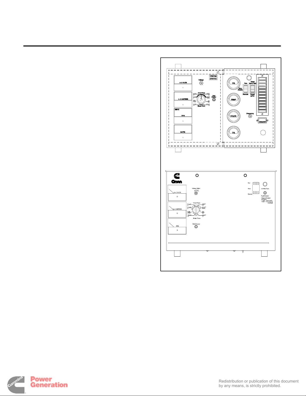
Detector 12 Control
This manual contains separate DC Control Wiring
and Prestart Preparation sections for gensets using
the Sentinel control or the Detector control (Figure
1-1). Refer to the Table of Contents for specific information relating to your genset. The remaining
sections apply to all versions.
This manual DOES NOT provide application information for selecting a generator set or designing the
complete installation. If it is necessary to design the
various integrated systems (fuel, exhaust, cooling,
etc.), additional information is required. Review
standard installation practices. For engineering
data specific to the generator set, refer to the specification and product data sheets. For application information, refer to Application Manual T-030, “Liquid Cooled Generator Sets”.
Sentinel Control
FIGURE 1-1. CONTROL PANEL CONFIGURATIONS
1-1

INSTALLATION OVERVIEW
Redistribution or publication of this document
by any means, is strictly prohibited.
These installation recommendations apply to typical installations with standard model generator
sets. Whenever possible, these recommendations
also cover factory designed options or modifications. However, because of the many variables in
any installation, it is not possible to provide specific
recommendations for every situation. If there are
any questions not answered by this manual, contact
your nearest Cummins/Onan dealer or distributor
for assistance.
Application and Installation
A standby power system must be carefully planned
and correctly installed for proper operation. This involves two essential elements: application and installation.
Application (as it applies to generator set installations) refers to the design of the complete standby
power system that usually includes power distribution equipment, transfer switches, ventilation equipment, mounting pads, and cooling, exhaust, and
fuel systems. Each component must be correctly
designed so the complete system will function as intended. Application and design is an engineering
function generally done by specifying engineers or
other trained specialists. Specifying engineers are
responsible for the design of the complete standby
system and for selecting the materials and products
required.
Installation refers to the actual set-up and assembly of the standby power system. The installers set
up and connect the various components of the system as specified in the system design plan. The
complexity of the standby system normally requires
the special skills of qualified electricians, plumbers,
sheetmetal workers, etc. to complete the various
segments of the installation. This is necessary so all
components are assembled using standard methods and practices.
Safety Considerations
The generator set has been carefully designed to
provide safe and efficient service when properly installed, maintained, and operated. However, the
overall safety and reliability of the complete system
is dependent on many factors outside the control of
the generator set manufacturer. To avoid possible
safety hazards, make all mechanical and electrical
connections to the generator set exactly as specified in this manual. All systems external to the generator (fuel, exhaust, electrical, etc.) must comply
with all applicable codes. Make certain all required
inspections and tests have been completed and all
code requirements have been satisfied before certifying the installation is complete and ready for service.
1-2
2. Specifications
Redistribution or publication of this document
by any means, is strictly prohibited.
MODEL GGFB GGFC
Engine
Onan Modified Ford In-line 6
Generator kW Rating
(See Genset Nameplate)
Fuel System Inlet Size
Natural Gas
Propane Vapor
Propane Liquid
Exhaust
Connection
Backpressure (Max. Allowed)
Electrical System
Starting Voltage
Battery Charging Alternator (Max. Rating)
Cooling System
Capacity with Standard Radiator
Lubricating System
Oil Capacity with Filters
CSG-649 CSG-649
1 inch NPT
3/4 inch NPT
1/4 inch NPT
2 inch NPT
20.4 inch H
12 Volts DC
37 A
5.8 Gal (22 L) 5.8 Gal (22 L)
7 Qts (6.6 L) 7 Qts (6.6 L)
O
2
1 inch NPT
3/4 inch NPT
1/4 inch NPT
2 inch NPT
20.4 inch H
12 Volts DC
37 A
2
O
2-1

Redistribution or publication of this document
by any means, is strictly prohibited.
2-2

3. Mounting the Generator Set
Redistribution or publication of this document
by any means, is strictly prohibited.
GENERAL
Most generator set installations must be engineered so the generator set will function properly
under the expected load conditions. Use these instructions as a general guide only. Follow the instructions of the consulting engineer when locating
or installing any components. The complete installation must comply with all local and state building
codes, fire ordinances, and other applicable regulations. Consider these requirements before installation:
• Level mounting surface
• Adequate cooling air
• Adequate fresh induction air
• Discharge of circulated air
WARNING
• Non-combustible mounting surface
• Discharge of exhaust gases
• Electrical connections
• Accessibility for operation and servicing
• Noise levels
• Vibration isolation
LOCATION
Generator set location is decided mainly by related
systems such as ventilation, wiring, fuel, and exhaust. The set should be located as near as possible to the main power fuse box.
Provide a location away from extreme ambient temperatures and protect the generator set from adverse weather conditions. An optional housing is
available for outside operation.
INCORRECT INSTALLATION, SERVICE OR REPLACEMENT OF PARTS CAN RESULT IN SEVERE PERSONAL INJURY OR DEATH, AND/OR EQUIPMENT DAMAGE. SERVICE PERSONNEL MUST BE QUALIFIED TO PERFORM ELECTRICAL AND MECHANICAL COMPONENT
INSTALLATION.
3-1

MOUNTING
Redistribution or publication of this document
by any means, is strictly prohibited.
Generator sets are mounted on a steel skid that provides proper support. The engine-generator assembly is isolated from the skid frame by rubber
mounts that provide adequate vibration isolation for
normal installations. For critical installations, install
vibration isolators between the skid base and foundation.
Mount the genset on a substantial and level base
such as a concrete pad. A non-combustible material must be used for the pad.
HEX NUT
FLAT WASHER
SKID
Use 3/4-inch diameter, anchored mounting bolts to
secure the generator set skid to the floor to prevent
movement. Secure the skid using a flat washer and
a hex nut for each bolt (Figure 3-1).
ACCESS TO SET
Plan for access to the genset for servicing and provide adequate lighting around the unit.
12 INCH
(305 mm)
MOUNTING BOLT
FIGURE 3-1. BOLT DIAGRAM
3-2

4. Mechanical Connections
Redistribution or publication of this document
by any means, is strictly prohibited.
GENERAL
The generator set mechanical system installation
includes connecting the fuel, exhaust, ventilation
and cooling systems. Before starting any type of
fuel installation, all pertinent state and local codes
must be complied with and the installation must be
inspected before the unit is put in service.
FUEL SYSTEM
Gensets can be equipped to operate on:
• LPG (vapor or liquid withdrawal)
• NG (natural gas) or
• Combination (NG/LPG)
In all fuel system installations, cleanliness is of the
upmost importance. Make every effort to prevent
entrance of moisture, dirt or contaminants of any
kind. Clean all fuel system components before
installing
A flexible fuel hose(s) or section of flexible fuel
hose(s) must be used between the engine’s fuel
system and fuel supply line(s) to protect the fuel
system from damage caused by vibration, expansion and contraction.
Installation of the fuel hose must be done according
to all applicable codes and standards, and installation recommendations provided by the manufacturer. The flexible hose used must be approved by the
hose manufacturer for use with the genset fuel type
and product application.
Natural Gas/LPG Vapor/LPG Liquid Fuel
System
WARNING
explosive and can cause severe personal injury
or death. Do not smoke if you smell gas or are
near fuel tanks or fuel-burning equipment or are
in an area sharing ventilation with such equipment. Keep flames, sparks, pilot lights, electrical arcs and arc-producing equipment and all
other sources of ignition well away. Keep a type
ABC fire extinguisher handy.
NFPA Standard No. 58 requires all persons handling and operating LPG to be trained in proper
handling and operating procedures.
Gaseous-fuel supply system design, materials,
components, fabrication, assembly, installation,
testing, inspection, operation and maintenance
must comply with the applicable codes. See NFPA
Standards No. 30, No. 37, No. 54 and No. 58.
Most codes require both manual and electric (battery-powered) shutoff valves ahead of the flexible
fuel hose(s). The manual valve should be of the indicating type. The electric valve should be wired so
that the valve is closed when the genset is off.
Install a dry-type fuel filter ahead of the service
pressure regulator to protect the sensitive pressure
regulating components and orifices downstream
from rust, scale and other solid substances carried
along in the gas stream.
See Specifications section for natural gas/LPG fuel
inlet size. The recommendations in Application
Manual T-030, should be followed in regard to fuel
supply system pipe sizes, manual shutoff valves,
fuel filters and gas pressure regulators.
Gaseous fuels are flammable and
4-1

Fuel Pressure
Redistribution or publication of this document
by any means, is strictly prohibited.
WARNING
gas leaks which can lead to fire and severe personal injury or death. Gas supply pressure must
be adjusted to Specifications by qualified personnel.
The gas pressure regulators in each line provide
constant gas pressure at the gas mixer under varying load conditions. There are pressure test ports
on both sides of the fuel regulator for measuring
supply and regulated fuel pressures (NG or LPG
systems). When measuring supply pressure, the
most accurate reading would be on the input side of
the solenoid valve.
Mixer side: The NG gas pressure should be
approximately 5 inches WC at full load.
The LP gas pressure will be approximately –0.5
inches WC at no load and –1.0 inch WC at full load.
High gas supply pressure can cause
Supply side: The minimum pressure refers to supply pressure under rated load (maximum gas flow).
For LPG (vapor withdrawal) and natural gas, the
maximum permissible fuel supply pressure is 13.6
inches WC and the recommended minimum is 7 inches WC.
For LPG (liquid withdrawal), the maximum permissible fuel supply pressure is 300 psi (2,070 kPa) under any operating condition.
WARNING
Gaseous fuel leaks into an inadequately ventilated space can lead to explosive
accumulations of gas. Natural gas rises when
released into the air and can accumulate under
overhanging hoods and inside housings and
buildings. LPG sinks when released into the air
and can accumulate inside housings, basements and other below-grade spaces. Precautions must be taken to prevent gas leaks and the
accumulation of gaseous fuel in the event of a
leak.
4-2

EXHAUST SYSTEM
Redistribution or publication of this document
by any means, is strictly prohibited.
Pipe exhaust gases to the outside of any enclosure.
Locate the exhaust outlets away from any air inlets
to avoid gases re-entering the enclosure. Exhaust
installations are subject to various detrimental conditions such as extreme heat, infrequent operation
and light loads. Regularly inspect the exhaust system both visually and audibly to see that the entire
system remains fume tight and safe for operation.
WARNING
Hot exhaust pipes can start a fire
and cause severe injury or death if improperly
routed through walls. Use an approved thimble
where exhaust pipes pass through walls or partitions.
WARNING
Inhalation of exhaust gases can result in severe personal injury or death. Do not
use exhaust heat to warm a room, compartment
or storage area.
WARNING
Inhalation of exhaust gases can result in severe personal injury or death. Use extreme care during installation to provide a tight
exhaust system. Terminate exhaust pipe away
from enclosed or sheltered areas, windows,
doors and vents.
For indoor installations, the exhaust system must
use sealed joint type fittings, (for example NPT fittings) to provide a tighter exhaust system. Use of
slip type fittings (secured with a muffler clamp) may
allow leakage of exhaust gases into the building.
WARNING
Inhalation of exhaust gases can result in severe personal injury or death. Use extreme care during installation to provide a tight
exhaust system. Use NPT or equivalent type fittings for all indoor installations.
Use an approved thimble (Figure 4-1) where exhaust pipes pass through wall or partitions. Refer to
NFPA 37, Section 6-3. “Stationary Combustion Engines and Gas Turbines” for accepted design practices. Build according to the code requirements in
effect at the installation site.
Rain caps are available for the discharge end of vertical exhaust pipes. The rain cap clamps onto the
end of the pipe and opens due to exhaust discharge
force from the generator set. When the generator
set is stopped, the rain cap automatically closes,
protecting the exhaust system from rain, snow, etc.
Use a section of flexible exhaust pipe between the
engine and remainder of exhaust system. Support
exhaust system to prevent weight applied to engine
exhaust outlet.
CAUTION
Weight applied to the engine manifold can result in damage. Support the muffler
and exhaust piping so no weight or stress is applied to engine exhaust.
The exhaust system design should meet local code
requirements.
WARNING
Liability for injury, death, damage,
and warranty expense due to use of unapproved mufflers or to modifications becomes
the responsibility of the person installing the
unapproved muffler or performing the modification. Contact an Onan distributor for approved
exhaust system parts.
4-3

Avoid sharp bends by using sweeping, long radius
Redistribution or publication of this document
by any means, is strictly prohibited.
elbows and provide adequate support for muffler
and tailpipe. Pitch a horizontal run of exhaust pipe
DOWNWARD (away from engine) to allow any
moisture condensation to drain away from the engine. If an exhaust pipe must be turned upward, install a condensation trap at the point where the rise
begins (Figure 4-2).
Shield or insulate exhaust lines if there is danger of
personal contact. Allow at least 12 inches (305 mm)
of clearance if the pipes pass close to a combustible
wall or partition.
WARNING
Exhaust pipes are very hot and they
can cause severe personal injury or death from
direct contact or from fire hazard. Shield or insulate exhaust pipes if there is danger of personal contact or when routed through walls or
near other combustible materials.
RAIN CAP
9 INCH
(230 mm)
VERTICAL
HORIZONTAL
DRIP CAP
HOLES IN
END OF INNER
SLEEVE
ROOF
9 INCH
(230 mm)
WALL OR PARTITION
FIGURE 4-1. MOUNTING EXHAUST THIMBLE
IF EXHAUST LINE MUST BE
PITCHED UPWARD, CONSTRUCT
A TRAP AT POINT OF RISE
AVOID
SHARP
BENDS
DRAIN CONDENSATION
TRAP PERIODICALLY
VALVE HANDLE SHOWN
IN OPEN POSITION
FIGURE 4-2. CONDENSATION TRAP
4-4

VENTILATION AND COOLING
Redistribution or publication of this document
by any means, is strictly prohibited.
Generator sets create considerable heat that must
be removed by proper ventilation. Outdoor installations rely on natural air circulation but indoor installations need properly sized and positioned vents for
required airflow.
Vents and Ducts
For indoor installations, locate vents so incoming air
passes through the immediate area of the installation before exhausting. Install the air outlet higher
than the air inlet to allow for convection air movement.
Size the vents and ducts so they are large enough to
allow the required flow rate of air. The ”free area” of
ducts must be as large as the exposed area of the
radiator. Refer to the GG Series Specification Sheet
for the airflow requirements and allowed airflow restriction.
Wind will restrict free airflow if it blows directly into
the air outlet vent. Locate the outlet vent so the effects of wind are eliminated or utilize a wind barrier if
necessary to minimize the effects of prevailing
winds. See Figure 4-3.
PREVAILING WINDS PREVAILING WINDS
NOT LESS THAN
HEIGHT OF OPENING
FIGURE 4-3. WIND BARRIER
4-5

Dampers
Redistribution or publication of this document
by any means, is strictly prohibited.
Dampers or louvres protect the generator set and
equipment room from the outside environment.
Their operation of opening and closing should be
controlled by operation of the generator set.
In cooler climates movable or discharge dampers
are used. These dampers allow the air to be recirculated back to the equipment room. This enables the
equipment room to be heated while the generator
set engine is still cold, increasing the engine efficiency.
Radiator Set Requirements
Radiator set cooling air is drawn past the rear of the
set by a pusher fan that blows air through the radiator (Figure 4-4). Locate the air inlet to the rear of the
set. Make the inlet vent opening 1-1/2 times larger
than the radiator area.
must be at least as large as the radiator area.
Length and shape of the air outlet duct should offer
minimum restriction to airflow.
Attach a canvas or sheet metal duct to the air outlet
opening using screws and nuts so duct can be removed for maintenance purposes. The duct prevents recirculation of heated air. For installations
that use a radiator discharge duct, the radiator core
guard can be removed. This will allow for slightly
less air flow restriction.
Remote Radiator Cooling (Optional) substitutes
a remote mounted radiator and an electrically
driven fan for the set mounted components. Removal of the radiator and the fan from the set reduces noise levels without forcing dependence on a
continuous cooling water supply. The remote radiator installation must be completely protected
against freezing.
Louvers and screens over air inlet and outlet openings restrict air flow and vary widely in performance.
A louver assembly with narrow vanes, for example,
tends to be more restrictive than one with wide
vanes. The effective open area specified by the louver or screen manufacturer should be used.
Locate the cooling air outlet directly in front of the radiator and as close as possible. The outlet opening
Remote radiator plumbing will vary with installation.
Follow recommendations given in Application Man-
ual T-030. See product Specification sheet for friction head and static head limits.
Before filling cooling system, check all hardware for
security. This includes hose clamps, capscrews, fittings and connections. Use flexible coolant lines
with heat exchanger or remote mounted radiator.
4-6

THIMBLE
Redistribution or publication of this document
by any means, is strictly prohibited.
EXHAUST
LINE
CONDENSATION
DRAIN PLUG
AIR OUT
MUFFLER
SWEEPING
ELBOW
CONTROL
WIRING
FLEXIBLE
SECTIONS
POWER
WIRING
AIR
IN
FLEXIBLE
BELLOWS
VIBRATION
ISOLATORS
IMPORTANT!
COOLING AIR INLET MUST BE AT LEAST 1-1/2 TIMES LARGER
THAN RADIATOR DUCT OUTLET AREA ON RADIATOR-COOLED
MODELS.
FLOW OF COOLING AIR AND HEATED AIR MAY BE
CONTROLLED BY AUTOMATICALLY OPERATED LOUVRES.
FIGURE 4-4. TYPICAL GENERATOR SET INSTALLATION
LEVEL
CONCRETE
BASE
4-7

Redistribution or publication of this document
by any means, is strictly prohibited.
4-8

5. DC Control Wiring (Detector Control)
Redistribution or publication of this document
by any means, is strictly prohibited.
CONTROL WIRING
The generator set control panel box contains connection points for remote control and monitor options. These connection points are located on the
engine control monitor board (ECM), the time-delay
module and the optional auxiliary relay board
(ARB). (Note that if the optional ARB is installed, no
remote monitor connections are attached to the
ECM. The ARB provides all remote monitor connection points.)
CAUTION
for all customer connections to the control panel box. Solid copper wire may break due to genset vibration.
The type/gauge wire to use for these connections
are:
Stranded copper wire must be used
• Less than 1000 feet (305m), use 18 gauge
stranded copper wire.
• 1000 to 2000 feet (305 to 610m), use 16 gauge
stranded copper wire.
CAUTION
a separate metal conduit from AC power cables
to avoid inducing currents that could cause
problems within the control.
WARNING
uninsulated high voltage parts inside the control panel box can result in severe personal injury or death. Control wire installation must be
done with care to avoid touching uninsulated
live parts.
For your protection, stand on a dry wooden platform or rubber insulating mat, make sure your
clothing and shoes are dry, remove jewelry and
use tools with insulated handles.
Always run control circuit wiring in
HAZARDOUS VOLTAGE Touching
5-1

ENGINE CONTROL MONITOR BOARD
Redistribution or publication of this document
by any means, is strictly prohibited.
(ECM-A11)
The heart of the engine control system is the engine
monitor (A11). It is a printed circuit board assembly
mounted on the back wall of the control box (Figure
5-1). It starts and stops the engine in response to
the control panel switches, engine sensors and remote control signals.
Remote Monitor Connections
The Detector control provides the capability of attaching a remote monitor panel. Connections are
made on the terminal blocks TB1 and TB2 located
on the ECM board. A detailed connection diagram
for the ECM board is provided in Section 10. (If the
optional ARB is installed, remote monitor connections attach to the ARB, not the ECM.)
Remote Start Connections
Connect remote start switch between A11-TB1-7
(B+) and A11-TB1-6 (RMT).
Function Selection Jumpers
The ECM board has six selection jumpers that can
be repositioned to provide the following timed or
non-timed warnings or timed or non-timed shutdowns with warnings:
W1 (12 light only) Jumper Position (jumper W8
must be in the B position):
A Non-timed warning under FLT 2 condi-
tions.
B (12 light only) Non-timed shutdown under
FLT 2 conditions.
C Timed warning under FLT 2 conditions.
D Timed shutdown under FLT 2 conditions.
W2 Jumper Position (jumper W9 must be in the B
position):
A Non-timed warning under FLT 1 condi-
tions.
B Non-timed shutdown under FLT 1 condi-
tions.
C Timed warning under FLT 1 conditions.
D Timed shutdown under FLT 1 conditions.
W6 Jumper Position:
A Warning under Pre-High Engine Tem-
perature conditions.
B Shutdown under Pre-High Engine Tem-
perature conditions.
W7 Jumper Position:
A Warning under Pre-Low Oil Pressure
conditions.
B Shutdown under Pre-Low Oil Pressure
conditions.
W8 (12 light only) Jumper Position:
A Warning while running or during standby
under FLT 2 conditions.
B Allows selection of functions with W1
jumper.
W9 (12 light only) Jumper Position:
A Warning while running or during standby
under FLT 1 conditions.
B Allows selection of functions with W2
jumper.
5-2

TB1
Redistribution or publication of this document
by any means, is strictly prohibited.
8 7 6 5 4 3 2 1 6 5 4 3 2 1
TB2
FIGURE 5-1. ENGINE CONTROL MONITOR BOARD (ECM)
5-3

AUXILIARY RELAY BOARD (OPTIONAL)
Redistribution or publication of this document
by any means, is strictly prohibited.
The following describes the design/functional criteria for the auxiliary relay board (ARB) with a Detector control. The board is mounted directly on top of
the ECM using standoffs and has access holes for
the fuses located on the ECM. A detailed connection diagram for the ARB is provided in Section 10.
Terminal Blocks:
• TB1 – ARB TB1 and engine monitor TB1 are
identically numbered and provide the same remote control connection points. Note that additional terminals are provided for terminals 5, 7,
and 10 of ARB TB1.
• TB2 through TB5 – Connection points for re-
lays K1 through K3. TB2 provides the N/O and
N/C connections (three form ‘C’ contacts for
each relay). TB3 through TB5 provide the common connection points (TB3 for K1, TB4 for K2
and TB5 for K3).
• TB6 and TB7 – Connection points for fault relays K4 through K15. Three terminals are provided for each relay, which are labeled COM,
N/C, N/O.
Plug-In Relays (K1, K2, K3): The ARB can be
equipped with one to three 3-pole, double-throw relays. These relays (K1, K2, K3) are field changeable
plug-in relays for easy field addition and replacement.
Each relay can be operated as a RUN, COMMON
ALARM, or ISOLATED COIL with the changing of a
jumper.
The relay contact ratings are:
• 10 amps at 28 VDC or 120 VAC, 80% PF
• 6 amps at 240 VAC, 80% PF
• Jumper Position A (Run) – The relay oper-
ates as a Run relay, energizing when SW B+ is
applied from the engine monitor.
• Jumper Position B (Common Alarm) – The
relay operates as a Common Alarm relay. The
relay energizes any time there is an engine
shutdown.
• Jumper Position C (Isolated) – The relay op-
erates as an Isolated relay. The relay coil is energized by a customer applied B+ signal
through the terminal block; TB3-1 for relay K1,
TB4-1 for relay K2, and TB6-1 for relay K3.
Jumpers W11, W12, and W13 perform the same
functions for their respective relays; W11 for relay
K1, W12 for relay K2, and W13 for relay K3. They
can be located in two different positions (A, B) independently of one another.
• Jumper Position A – The relay operates iso-
lated from the board. The customer provides
the circuit completion through terminal block;
TB3 for relay K1, TB4-5 for relay K2, and TB6-5
for relay K3. The customer can operate the relay with switched ground logic or use this relay
in the middle of more complex logic circuits if
needed.
• Jumper Position B – The relays operate with
the coils connected to ground through the
board connections. The coil will require a B+
signal to energize with the jumper in this position.
Fault Relays (K4 through K15): These relay modules are used to operate a remote alarm annunciator that has an independent power source. This allows the use of either AC or DC for alarm drives. The
relays are energized through the latching relays on
the engine monitor and provided N/O and N/C contacts for each external alarm connection.
• 3 amps at 480 VAC, 80% PF
Jumper Positions for Plug-In Relays: Jumpers
W1, W2 and W3 perform the same functions for
their respective relays, W1 for relay K1, W2 for relay
K2, and W3 for relay K3. They can be located in any
of 3 positions (A, B, C) independently of each other.
The 12 relays with form ‘C’ contacts are rated:
• 10 Amp, 120 VAC
• 10 Amp. 30 VDC
5-4

JUMPERS JUMPERS
Redistribution or publication of this document
by any means, is strictly prohibited.
K1 K2 K3
J1, J2 WIRE
HARNESS PLUG
CONNECTIONS
FROM A11
RUN RELAY
MODULE(S)
FIGURE 5-2. AUXILIARY RELAY BOARD (ARB)
5-5

TIME-DELAY MODULE (A15) (OPTIONAL)
Redistribution or publication of this document
by any means, is strictly prohibited.
The start delay module is adjustable from 5 to 15 seconds and the stop delay from 30 seconds to 30
minutes. Turn the delay adjusting potentiometers
clockwise to increase delay and counterclockwise
to decrease delay.
Remote Control Connections
Remote control connections are made at the terminal block (TB1) that is located on the time-delay
module (Figure 5-3). Connect one or more remote
switches across the remote terminal (TB1-5) of the
time-delay module and the B+ terminal of the ECM
(A11).
PRIMARY START-DISCONNECT
A11 - TB1-2
SECONDARY START-DISCONNECT
(A11 – TB1-3
START DELAY
POTENTIOMETER
TB1
12345 6
RUN SIGNAL OUT (A11 - TB1-6
RUN SIGNAL IN (REMOTE
START/STOP CONTROL
STOP DELAY
POTENTIOMETER
B– (A11 - TB1-5
B+ (A11 - TB1-7)
FIGURE 5-3. PREHEAT/TIME-DELAY MODULE
5-6

6. DC Control Wiring (Sentinel Control)
Redistribution or publication of this document
by any means, is strictly prohibited.
CONTROL WIRING
The generator set control panel box contains connection points for remote starting and switched B+
connections. Connections are made on the terminal
block (TB1) located inside the control box (Figure
6-1).
Connect a remote switch across remote terminal
(TB1-4) and B+ (TB1-3) for remote starting.
Switched B+ auxiliary power is available when the
generator set is running. When connecting customer accessories to the 12 volt B+ auxiliary terminals
(TB1-1 & 2), do not allow the current exceed 7
amps.
If the distance between the genset and the remote
station is less than 1000 feet (305 m), use 18 gauge
stranded copper wire. If the distance is 1000 to 2000
feet (305 to 610 m), use 16 gauge stranded copper
wire. Always run control circuit wiring in a separate
metal conduit from AC power cables to avoid inducing currents that could cause problems within the
control.
WARNING
HAZARDOUS VOLTAGE Touching
uninsulated high voltage parts inside the control panel box can result in severe personal injury or death. Control wire installation must be
done with care to avoid touching uninsulated
live parts.
For your protection, stand on a dry wooden platform or rubber insulating mat, make sure your
clothing and shoes are dry, remove jewelry and
use tools with insulated handles.
CONTROL BOX
TB1
GROUND
5
REMOTE
4
B+
3
SWITCHED B+
2
SWITCHED B+
1
TB1
FIGURE 6-1. REMOTE CONTROL CONNECTION POINTS
6-1

DRY CONTACT MODULE (Optional)
POSITION
Redistribution or publication of this document
by any means, is strictly prohibited.
The dry contract module provides the capability of
attaching a remote monitor device. Connections
are made to the terminals of relays K8 and K9 lo-
cated on the dry contact module (Figure 6-2). A detailed connection diagram for the dry contact module is provided in Section 10.
The relay contact ratings are:
The following faults will activate relays K8 or K9 as
follows:
RELAY K8 RELAY K9
Over Crank
Low Oil Pressure
High Engine Temperature
Low Coolant Level
Overspeed
Low Fuel Pressure
CONTACT
Max carry/break 40 A 30 A 20 A 10 A
Max make 100 A 60 A 50 A 20 A
12V COIL
VOLTAGE
N.O. N.C. N.O. N.C.
24V COIL
VOLTAGE
CONTROL BOX
DRY CONTACT
MODULE
FIGURE 6-2. DRY CONTACT MODULE
6-2

7. AC Electrical Connections
Redistribution or publication of this document
by any means, is strictly prohibited.
GENERAL
This section provides the procedure that is used to
connect the AC electrical system of the genset.
Disconnect the battery charger and the battery
cables (negative [–] first) to prevent accidental starting while working on the set.
CAUTION
charger from its AC source before disconnecting the battery cables. Otherwise, disconnecting the cables can result in voltage spikes high
enough to damage the DC control circuits of the
set.
WARNING
set while working on it can cause severe personal injury or death. Prevent accidental starting by disconnecting the starting battery cables
(negative [–] first).
Make certain battery area has been well ventilated before servicing battery, especially if a
battery charger has been connected. Arcing
can ignite explosive hydrogen gas given off by
batteries, causing severe personal injury. Arcing can occur when cable is removed or re-attached, or when negative (–) battery cable is
connected and a tool used to connect or disconnect positive (+) battery cable touches frame or
other grounded metal part of the set.
Always disconnect a battery
Accidental starting of the generator
Connecting the genset AC electrical system involves:
• Installation of transfer switch (standby service
only)
• Generator voltage connections
• Load connection
• Standard and optional AC equipment connec-
tions (e.g., control box heater, coolant heater,
etc.).
Local regulations often require that wiring connections be made by a licensed electrician, and that the
installation be inspected and approved before operation. All connections, wire sizes, materials used,
etc. must conform to the requirements of electrical
codes in effect at the installation site.
Generator set output requires approved protective
devices or means in compliance with the NEC (National Electric Code) and applicable local regulations.
WARNING
electrocution, resulting in severe personal injury or death and/or property and equipment damage.
Before starting the genset, verify that all electrical
connections are secure, and that all wiring is complete. Replace and secure any access panels that
have been removed during installation. Check that
the load cables from the genset are properly connected.
Improper wiring can cause a fire or
WARNING
this section should be done only by persons
trained and experienced in electrical maintenance. Improper procedures may result in
property damage, bodily injury or death.
Each of the operations described in
WARNING
cause electrocution or property damage. Do not
connect to any building electrical system except through an approved device and after
building main switch is opened.
Backfeed to utility system can
7-1

TRANSFER SWITCH
Redistribution or publication of this document
by any means, is strictly prohibited.
If the installation is for standby service, a transfer
switch must be used for switching the load from the
normal power source to the genset (see Figure 7-1).
Either a manual or automatic transfer switch may be
used. Follow the installation instructions provided
with the transfer switch when connecting the load
and control wiring.
LOAD
NORMAL
SOURCE
FIGURE 7-1. TYPICAL LOAD TRANSFER
FUNCTION
GENSET
7-2

AC WIRING
Redistribution or publication of this document
by any means, is strictly prohibited.
Generator Voltage Connections
The generator output voltage and maximum current
rating are specified on the generator set nameplate.
Line-to-neutral voltage is always the lower voltage
shown and line-to-line voltage is the higher rating.
mounted circuit breakers are provided, connections
can be made directly to the circuit breakers.
The terminals of the reconnection block are
stamped U, V, W and N to indicate the line and neutral connections. (Reference: U, V, and W correspond with L1, L2 and L3; and N with L0 respectively).
These generators can be configured for the voltages shown in the Reconnection Diagram on the
side access cover of the control housing. Most of
these voltages must be reconnected by the installer
to give the voltage required by the installation. Before shipping, the factory tests the generator set
output by connecting the generator to produce a
particular test voltage. The generator may be connected at the factory to produce a specified voltage
per customer order. The installer must always
check the stator lead terminal block connections
and perform any necessary reconnect to obtain the
voltage desired.
Some generator sets are capable of producing a
wide range of voltages and connection configurations, others have specific limited capabilities. Refer to wiring diagram and generator voltages (from
the nameplate) when reviewing the voltage connection information and use the electrical schematic
supplied with your generator set when actually performing load connections.
CAUTION
Reconnecting factory connected
generator sets to higher voltages can exceed
the voltage capability of the specific generator
windings and damage the generator. Consult
with your distributor before performing reconnection for a different voltage.
CAUTION
Reconnecting factory connected
generator sets to lower voltages can reduce set
ratings, and also render line circuit breakers too
small. Consult with your distributor before performing reconnection for a different voltage.
Load Connections
Flexible conduit and stranded conductors must be
used for connections to take up movement of the
generator set.
All loads are connected to the generator by bolting
stranded load wires to the appropriate terminals on
the generator reconnection terminal block or if
Load Balancing
When connecting loads to the generator set, balance the loads so the current flow from each line terminal (L1, L2 and L3) is about the same. This is especially important if both single phase and three
phase loads are connected. Any combination of single phase and three phase loading can be used as
long as each line current is about the same, within
10 percent of median value and no line current exceeds the nameplate rating of the generator. Check
the current flow from each line after connections by
observing the control panel ammeter (if provided).
Current Transformers
Current transformers (CT’s) are required on gensets that contain AC meters. The CT’s must be
installed as noted in the following CT Installation
Requirements.
Refer to the Reconnection Diagram to identify the
output leads/phase that must be routed through
each CT, and also appropriate transformer post
selection for meter sensing leads. The transformers
are labeled CT21, CT22 and CT23 on the reconnection wiring diagram. (The Reconnection Diagram is located on the upper side cover of the control housing.)
CT Installation Requirements:
A. The CT has a dot on one side. This dot must be
facing toward the generator (conventional current flowing into the dot). A dot is also used to
indicate pin 1 of the CT.
B. CT21 – U load leads (A phase),
CT22 – V load leads (B phase)
CT23 – W load leads (C phase)
C. Route the appropriate load wires through each
CT.
D. The CT’s have dual secondaries (3 pins). The
CT secondary wire marked 1 is connected to
pin 1 of the CT. CT secondary wire marked 2/3
is connected to pin 2 for high voltage gensets or
to pin 3 for low voltage gensets. (Refer to Reconnection Diagram.)
7-3

Grounding
Redistribution or publication of this document
by any means, is strictly prohibited.
The following is a brief description of system and
equipment grounding of permanently installed AC
generators within a facility wiring system. It is
important to follow the requirements of the local
electrical code.
WARNING
Contact with electrical equipment
can result in severe personal injury or death. It
is extremely important that bonding and equipment grounding be properly done. All metallic
parts that could become energized under abnormal conditions must be properly grounded.
Figure 7-2 illustrates typical system grounding for a
3-pole and a 4-pole automatic transfer switch
(ATS). In the 3-pole ATS, note that the generator
neutral is connected to the ATS and is NOT bonded
to ground at the generator. In the 4-pole ATS system, a grounding electrode conductor and a bonding jumper are used to connect the generator neutral to ground. In some installations, a CT may be
required for ground fault monitoring (refer to Figure
7-2 for CT location).
3-POLE AUTOMATIC
TRANSFER SWITCH
3∅
TO UTILITY
SERVICE
N
Typical requirements for bonding and grounding
are given in the National Electrical Code, Article
250. All connections, wire sizes, etc. must conform
to the requirements of the electrical codes in effect
at the installation site.
GENERATOR SETSERVICE ENTRANCE
3∅
N
TO UTILITY
SERVICE
SERVICE ENTRANCE
FIGURE 7-2. TYPICAL SYSTEM GROUNDING ONE-LINE DIAGRAMS
4-POLE AUTOMATIC
TRANSFER SWITCH
4 WIRES & GROUND
TO LOAD
GENERATOR SET
4 WIRES & GROUND
TO LOAD
BONDING
JUMPER
CT LOCATION IF
REQUIRED FOR
GFI MONITORING
GROUNDING
ELECTRODE
CONDUCTOR
7-4

CONTROL HEATER (OPTIONAL)
Redistribution or publication of this document
by any means, is strictly prohibited.
A control heater (Figure 7-3) provides a means of
humidity /temperature control for the Detector control box interior. It protects the components when
the generator set is subjected to varying ambient air
conditions during extended periods of non-use.
The heater is equipped with a power cord that terminates with a 120V or 220V NEMA plug.
HEATER
TO ACCESSORY BOX
A40–TB1-36 & 37
(PCC CONTROL)
FIGURE 7-3. OPTIONAL CONTROL HEATER
TO 120/240 VAC SUPPLY
(DETECTOR CONTROL)
BOTTOM VIEW OF
CONTROL BOX
7-5

COOLANT HEATER (OPTIONAL)
Redistribution or publication of this document
by any means, is strictly prohibited.
A coolant heater (emersion or tank) is used to keep
the engine coolant warm when the engine is shut
down. It heats and circulates the coolant within the
engine. This reduces startup time and lessens engine wear caused by cold starts. It is electrically operated and thermostatically controlled.
The heater is equipped with a power cord that terminates with a 120V or 220V NEMA plug.
Connect the heater to a source of power that will be
on during the time the engine is not running. Be sure
the voltage rating is correct for the heater element
rating.
WARNING
The coolant heater must not be operated while the cooling system is empty or
damage to the heater will occur.
TUBE
HOSE
OUTLET
TUBE
HOSE
HEATER
POWER
PLUG
INLET
FIGURE 7-4. COOLANT HEATER
7-6

GENERATOR HEATER (OPTIONAL)
Redistribution or publication of this document
by any means, is strictly prohibited.
A generator heater(s) is used to help keep the generator free of condensation when the generator set
is not running. During cool and humid conditions,
condensation may form within a generator, creating
flashing and shock hazards.
Figure 7-5 illustrates the installation of two heater
elements. Connect the heater(s) to a source of power that will be on during the time the engine is not
running. Power connections are made to the terminal block in the heater terminal box. Be sure the voltage rating is correct for the heater element rating.
WARNING
Water or moisture inside a generator increases the possibility of flashing and
electrical shock, which can cause equipment
damage and severe personal injury or death. Do
not use a generator which is not dry inside and
out.
HEATER
LEADS
HEATER
HEATER
TERMINAL BOX
(VIEW AA)
FIGURE 7-5. TYPICAL GENERATOR HEATER INSTALLATION
7-7

Redistribution or publication of this document
by any means, is strictly prohibited.
7-8

8. Prestart Preparation (Detector/Sentinel)
Redistribution or publication of this document
by any means, is strictly prohibited.
GENERAL
Before attempting the initial start of the generator
set, be sure to complete the Installation Checklist in
Section 9.
ELECTRICAL SYSTEM
Verify all electrical connections are secure and all
wiring is complete and inspected. Replace and secure any access panels that may have been removed during installation.
Battery Connections
WARNING
set can cause severe personal injury or death.
Make sure that the Run/Off/Auto switch on the
control panel is set to the Off position before
connecting the battery cables.
Starting the unit requires a 12 volt battery. Connect
positive battery cable before connecting negative
battery cable to prevent arcing.
Accidental starting of the generator
Service the battery as necessary. If an automatic
transfer switch is installed without a built-in charge
circuit, connect a separate battery charger.
WARNING
can cause severe personal injury. Always connect battery negative last to prevent arcing.
WARNING
ventilated prior to servicing near it. Lead-acid
batteries emit a highly explosive hydrogen gas
that can be ignited by arcing, sparking, smoking, etc.. Ignition of these gases can cause severe personal injury.
Ignition of explosive battery gases
Be sure battery area has been well-
STARTING
Refer to the generator set Operator’s manual for important safety precautions and recommended procedures to start the genset and to confirm proper
operation. Start the generator set and verify all engine and generator gauges are displaying the correct values.
8-1

Redistribution or publication of this document
by any means, is strictly prohibited.
8-2

9. Installation Checklist
Redistribution or publication of this document
by any means, is strictly prohibited.
GENERAL
Generator set wattage capacity is sufficient to handle maximum anticipated load.
At least 3 feet of clearance is provided around entire genset for servicing and ventilation.
Generator set is located in an area not subject to flooding.
All operating personnel have read and are familiar with Operator’s Manual.
All operators have been thoroughly briefed on correct operation and exercise procedures.
All operators have been thoroughly briefed on preventive maintenance procedures.
All operators have read and understand all Safety Precautions in Operator’s Manual.
GENSET SUPPORT
Floor, roof or earth on which the genset rests is strong enough and will not allow shifting
or movement. Observe local codes on soil bearing capacity due to freezing and thawing.
Generator set is properly supported and retained to approved base which is separate and independent of the surface on which it sits. Vibration isolators are installed between base and set.
Supporting base is large enough and is of non-combustible material - extends 12-inches all
around set.
COOLING AIR FLOW
Generator set air inlet is faced into direction of strongest, prevailing winds.
Air inlet openings are unrestricted and at least 1-1/2 times larger than air outlet area.
Cooling air outlet is on downwind side of building (if not, wind barrier is constructed).
Proper ducting material (sheet metal, canvas) is used between radiator and air outlet.
FUEL SYSTEM
Fuel tanks meet or exceed all local, state or national codes.
Fuel lines are properly installed, supported and protected against damage.
Approved flexible fuel line is installed between main fuel supply line and the generator set’s fuel
system, near the generator set, to protect the fuel system from damage caused by vibration,
expansion and contraction.
Fuel line shutoff valves are installed to prevent fuel flow in case of leaks.
No fuel leaks are found in supply line or engine fuel system.
9-1

EXHAUST SYSTEM
Redistribution or publication of this document
by any means, is strictly prohibited.
Operators are thoroughly briefed on the dangers of carbon monoxide gas, preventing
the buildup of this gas in inhabited areas.
Areas around set are well ventilated. No possibility of exhaust fumes entering building
doors, windows, or intake fans.
Exhaust gases are piped safely outside and away from building.
The correct length of approved rigid pipe is connected to the genset flexible pipe using
approved securing methods with no weight resting on engine exhaust components.
There are no bends in flex section.
Condensation drain is provided in lowest section of exhaust piping.
Exhaust piping is insulated to guard against burns to personnel.
Exhaust piping passing through walls or ceilings have approved fire-proof materials and
are in compliance with all codes.
Exhaust piping is large enough in diameter to prevent back pressure on engine.
Rain cap is installed if required.
AC AND DC WIRING
Wire sizes, insulation, conduits and connection methods all meet applicable codes.
AC and DC wires are separated in their own conduit to prevent electrical induction.
All load, line and generator connections are proper and correct.
GENSET PRESTART
Generator set engine is properly serviced with oil and coolant.
Batteries are properly installed, serviced and charged.
Battery charger and engine coolant heater are connected and operational.
All genset covers and safety shields are installed properly.
All fuel and coolant shutoff valves are operational.
9-2

10. Wiring Diagrams
Redistribution or publication of this document
by any means, is strictly prohibited.
GENERAL
This section consists of the schematic and connection wiring diagrams referenced in the text. The following drawings are included.
Detector Control
Page 10-2 – Customer Connections at the En-
•
gine Monitor Board (Detector Control)
• Page 10-3 – Customer Connections at the Aux-
iliary Relay Board (Detector Control)
• Page 10-4 – Accessory Interconnect Diagram
(Detector Control)
Sentinel Control
•
Page 10-5 – DC Wiring (Sentinel)
10-1

10-2
CUSTOMER CONNECTIONS AT THE ENGINE MONITOR BOARD (DETECTOR CONTROL)
TB2-1 (FAULT 2) GROUND INPUT FROM SENDER
TB2-2 (FAULT 2) GROUND OUTPUT TO LIGHT/RELAY*
TB2-3 (FAULT 1) GROUND INPUT FROM SENDER
TB2-4 (FAULT 1) GROUND OUTPUT TO LIGHT/RELAY*
TB2-6 (OVERCRANK FAULT) GROUND OUTPUT TO LIGHT/RELAY*
TB2-7 (OVERSPEED FAULT) GROUND OUTPUT TO LIGHT/RELAY*
TB2-8 (HIGH ENGINE TEMPERATURE FAULT) GROUND OUTPUT TO LIGHT/RELAY*
TB2-9 (LOW OIL PRESSURE FAULT) GROUND OUTPUT TO LIGHT/RELAY*
TB2-11 (PRE-LOW OIL PRESSURE WARNING) GROUND OUTPUT TO LIGHT/RELAY*
TB2-13 (LOW ENGINE TEMPERATURE WARNING) GROUND OUTPUT TO LIGHT/RELAY*
TB2-5 (REMOTE RESET) MOMENTARY CONTACT TO GROUND
TB2-10 (PRE-HIGH ENGINE TEMPERATURE WARNING) GROUND OUTPUT TO LIGHT/RELAY*
TB2-12 (SWITCH OFF WARNING) GROUND OUTPUT TO LIGHT/RELAY*
TB2-14 (LOW FUEL WARNING) GROUND INPUT FROM SENDER
TB2-15 (LOW FUEL WARNING) GROUND OUTPUT TO LIGHT/RELAY*
TB2-16 (EMERGENCY SHUT DOWN) MOMENTARY CONTACT TO GROUND
TB1-9 (B+ INPUT) BATTERY POSITIVE (+) CONNECTION
TB1-8 (START SOLENOID) FUSED AT 20 AMPS
TB1-7 (B+ OUTPUT) OUTPUT TO TIME DELAY START/STOP MODULE A15 (WHEN USED),
FUSED AT 15 AMPS, AVAILABLE WHEN THE STARTING BATTERIES ARE CONNECTED
TB1-6 (REMOTE START) CONNECTED TO TIME DELAY START/STOP MODULE A15 (WHEN USED). CONNECT
REMOTE START CONTACT OF THE AUTOMATIC TRANSFER SWITCH TO TERMINAL TB1-5 OF MODULE A15
(WHEN USED) OR TB1-6 OF EMB
TB1-5 (GROUND)
TB1-4 (COMMON ALARM B+ OUTPUT) 4 AMP RATED DEVICE MAXIMUM
TB1-3 (RUN) CONNECTED TO TIME DELAY START/STOP MODULE A15 (WHEN USED)
TB1-2 (DC DISCONNECT) CONNECTED TO TIME DELAY START/STOP MODULE A15 (WHEN USED)
+–
TB1-10 (SWITCHED B+ OUTPUT) FUSED AT 20 AMPS, ENERGIZED WHEN THE
START SIGNAL IS APPLIED AND DE-ENERGIZED AT SHUTDOWN (NORMAL AND FAULT)
CUSTOMER SUPPLIED WIRING
FACTORY WIRING
* 0.5 AMP RATED DEVICE MAXIMUM
K12
K11
A15
Redistribution or publication of this document
by any means, is strictly prohibited.

CUSTOMER CONNECTIONS AT THE AUXILIARY RELAY BOARD (DETECTOR CONTROL)
10-3
THE TERMINALS IN THE SHADED BOXES ARE FOR CUSTOMER CONNECTIONS
625-2712
NO. 300Ć4111
REV. B
MODIFIED
THIS IS A REPRESENTATIVE (GENERIC)
SCHEMATIC/WIRING DIAGRAM. FOR
TROUBLESHOOTING, REFER TO THE
WIRING DIAGRAM PACKAGE THAT WAS
INCLUDED WITH YOUR GENSET.
Redistribution or publication of this document
by any means, is strictly prohibited.

10-4
ACCESSORY INTERCONNECT DIAGRAM (DETECTOR CONTROL)
No. 630Ć1345 sh 3
Rev. H
Modified 02/28/96
THIS IS A REPRESENTATIVE (GENERIC)
SCHEMATIC/WIRING DIAGRAM. FOR
TROUBLESHOOTING, REFER TO THE
WIRING DIAGRAM PACKAGE THAT WAS
INCLUDED WITH YOUR GENSET.
Redistribution or publication of this document
by any means, is strictly prohibited.

DC DIAGRAM (SENTINEL)
10-5
No. 612Ć6697 sh 3 of 4
Rev. M Sys: ProE
Modified 4/13/98
Redistribution or publication of this document
by any means, is strictly prohibited.

Cummins Power Generation
Redistribution or publication of this document
by any means, is strictly prohibited.
1400 73rd Avenue N.E.
Minneapolis, MN 55432
1-800-888-6626
763-574-5000 International Use
Fax: 763-528-7229
Cummins is a registered trademark of Cummins Inc.
 Loading...