

CUMMINS RA SERIES, RA112L1 Owner's Manual

OwnerOwner ManualManual
Automatic Transfer Switch
RA Series
RA112L1 (Spec A)
English
Original Instructions 10-2016 A052S254 (Issue 2)


Table of Contents
1. IMPORTANT SAFETY INSTRUCTIONS....................................................................................... 1
1.1 Warning, Caution, and Note Styles Used in This Manual ..................................................... 1
1.2 General Information ................................................................................................................ 1
1.2.1 General Precautions .................................................................................................... 1
1.3 Electrical Shock and Arc Flash Can Cause Severe Personal Injury or Death ....................... 2
1.3.1 Utility Supply and Isolation........................................................................................... 2
1.3.2 Utility-to-Generator Set Applications............................................................................ 2
2. INTRODUCTION............................................................................................................................ 5
2.1 Owner Manual......................................................................................................................... 5
2.2 Transfer Switch Application .................................................................................................... 6
2.3 Transfer Switch Function........................................................................................................ 7
2.4 Model Identification................................................................................................................. 8
2.5 How to Obtain Service............................................................................................................ 8
2.6 Application and Installation..................................................................................................... 9
3. INSTALLATION............................................................................................................................ 11
3.1 Installation Overview............................................................................................................. 11
3.1.1 Safety Considerations................................................................................................ 11
3.2 Installation - Mounting........................................................................................................... 11
3.2.1 Introduction ................................................................................................................ 11
3.2.2 Equipment Inspection and Storage............................................................................ 12
3.2.3 Location...................................................................................................................... 12
3.2.4 Installing an Automatic Transfer Switch..................................................................... 12
3.2.5 Mounting Method ....................................................................................................... 14
3.3 Installation - Wiring ............................................................................................................... 14
3.3.1 AC Connections ......................................................................................................... 15
3.3.2 Low Voltage Signal Connections............................................................................... 17
3.3.3 Final Inspection and Cleanup .................................................................................... 19
4. TROUBLESHOOTING ................................................................................................................. 21
4.1 Introduction ........................................................................................................................... 21
4.2 Troubleshooting Procedures for Experienced Service Personnel........................................ 21
4.2.1 Utility-to-Generator Set Sequence of Events............................................................. 21
4.2.2 Generator-to-Utility Sequence of Events ................................................................... 21
4.2.3 Troubleshooting with Symptoms................................................................................ 22
4.2.4 Important Troubleshooting Reminders....................................................................... 22
4.2.5 Troubleshooting for Transfer Switches...................................................................... 22
5. TRANSFER SWITCH SERVICE.................................................................................................. 25
5.1 Introduction ........................................................................................................................... 25
5.2 Switch Removal and Replacement Procedure ..................................................................... 25
5.2.1 Disconnect AC Power................................................................................................ 25
iA052S254 (Issue 2) Copyright © 2016 Cummins Inc.

Table of Contents 10-2016
5.2.2 Transfer Switch Mechanism Removal ....................................................................... 26
5.2.3 Transfer Switch Replacement.................................................................................... 26
5.2.4 Reconnect AC Power (When Finished)..................................................................... 26
5.3 Control Relay (K1) Replacement Procedure ........................................................................ 27
5.4 Utility Sense Relay (K2) Replacement Procedure................................................................ 28
APPENDIX A. PARTS INFORMATION ........................................................................................... 31
APPENDIX B. WIRING DIAGRAMS................................................................................................. 35
B.0 RA112L1 Automatic Transfer Switch Wiring Diagram.......................................................... 37
B.1 RA112L1 Automatic Transfer Switch Interconnection Diagram........................................... 39
ii A052S254 (Issue 2)Copyright © 2016 Cummins Inc.

1 Important Safety Instructions
Save these instructions. This manual contains important instructions that should be followed during
installation and maintenance of the transfer switch.
Safe and efficient operation can be achieved only if the equipment is properly operated and maintained.
Many accidents are caused by failure to follow fundamental rules and precautions.
1.1 Warning, Caution, and Note Styles Used in This
Manual
The following safety styles and symbols found throughout this manual indicate potentially hazardous
conditions to the operator, service personnel, or equipment.
DANGER
Indicates a hazardous situation that, if not avoided, will result in death or serious injury.
WARNING
Indicates a hazardous situation that, if not avoided, could result in death or serious injury.
CAUTION
Indicates a hazardous situation that, if not avoided, could result in minor or moderate injury.
Indicates information considered important, but not hazard-related (e.g., messages relating to
property damage).
1.2 General Information
This manual should form part of the documentation package supplied by Cummins Power Generation with
specific transfer switches. In the event that this manual has been supplied in isolation please contact your
authorized distributor.
It is in the operator’s interest to read and understand all warnings and cautions contained within
the documentation relevant to the generator set, its operation and daily maintenance.
1.2.1 General Precautions
Refer to NFPA 70E Standard for Electrical Safety in the Workplace to be sure the proper personal
protective equipment (PPE) is worn around this product.
NOTICE
NOTICE
1A052S254 (Issue 2) Copyright © 2016 Cummins Inc.

1. Important Safety Instructions 10-2016
Follow these guidelines while working on or around electrical equipment.
• Place rubber insulated mats on dry wood platforms over metal or concrete floors when working on
any electrical equipment.
• Do not wear damp clothing (particularly wet shoes) or allow skin surfaces to be damp when handling
any electrical equipment.
• Remove all jewelry when working on electrical equipment.
• Wear safety glasses whenever servicing the transfer switch.
• Do not smoke near the batteries.
• Do not work on this equipment when mentally or physically fatigued, or after consuming alcohol or
any drug that makes the operation of equipment unsafe.
WARNING
Incorrect service or replacement of parts can result in death, severe personal injury, and/or
equipment damage. Service personnel must be qualified to perform electrical and/or mechanical
service.
1.3 Electrical Shock and Arc Flash Can Cause Severe Personal Injury or Death
High voltage in transfer switch components presents serious shock hazards that can result in severe
personal injury or death. Read and follow these suggestions:
• The Operator must always keep the transfer switch covers installed.
• Make sure only authorized personnel remove the covers.
• All installation, service, and adjustments to the transfer switch must be performed only by an
electrician or authorized service representative.
1.3.1 Utility Supply and Isolation
It is the sole responsibility of the customer to provide AC power conductors for connection to load
devices and the means to isolate the AC input to the terminal box; these must comply with local
electrical codes and regulations. Refer to the wiring diagram supplied with the generator set.
Local electrical codes and regulations (for example, the National Electrical Code or the Canadian
Electrical Code) may require the installation of a disconnect means for the generator set, either
on the generator set or where the generator set conductors enter a facility.
The utility disconnecting device is not provided as part of the generator set or automatic transfer switch,
and Cummins Power Generation accepts no responsibility for providing the means of isolation.
NOTICE
1.3.2 Utility-to-Generator Set Applications
If the cabinet must be opened for any reason:
1. Press the stop button on the local control at the generator set.
2. Turn off AC power supplying the battery charger and all accessories.
3. Disconnect the starting batteries of the generator set or sets, removing the ground (-) lead first.
2 A052S254 (Issue 2)Copyright © 2016 Cummins Inc.

1. Important Safety Instructions10-2016
4. Remove utility power to the automatic transfer switch. If the instructions require otherwise, use
extreme caution due to the danger of shock hazard.
WARNING
AC power within the cabinet presents a shock hazard that can cause severe personal injury or
death.
3A052S254 (Issue 2) Copyright © 2016 Cummins Inc.

1. Important Safety Instructions 10-2016
This page is intentionally blank.
4 A052S254 (Issue 2)Copyright © 2016 Cummins Inc.

2 Introduction
2.1 Owner Manual
This manual covers models produced under the Cummins®Power Generation (CPG) brand names.
This manual provides information necessary for operation, installation, and service of RA series RA112L1
transfer switches. This manual also includes parts information.
This is an open transition transfer switch which does not include an integral automatic transfer switch
control. With an open transition switch, there is never a time when both sources are supplying power to
the load. The design prevents accidental connection of the generator set to the utility.
This manual includes information on the RA Series RA112L1 transfer switch installation.
RA Series transfer switches are designed to only be installed with the Cummins generator set models
shown below. Installing these switches with any other generator set models will void the warranty.
Cummins Generator Set Models Using RA Series Transfer Switches
C10 D6 C25 D6 C40 D6
C13N6H* C25 N6 C40 N6
C15 D6 C30 D6 C40 N6H
C17N6H* C30 N6 C45 N6H
C20 D6 C30 N6H C50 N6H
C20 N6 C35 D6 C60 N6H
C20N6H* C36 N6
C22 N6 C36 N6H
* Requires TB4 Jumper.
Refer to the wiring diagrams at the end of this manual for specific information about switch configuration.
Use normal and necessary safety precautions before starting any service procedure. Identify all hazards
by referring to the Important Safety Instructions section of this manual and by observing all warnings and
cautions within the manual. Whenever you are troubleshooting, remember that the generator set, the
transfer switch, and the utility power source are all interdependent.
5A052S254 (Issue 2) Copyright © 2016 Cummins Inc.
2. Introduction 10-2016
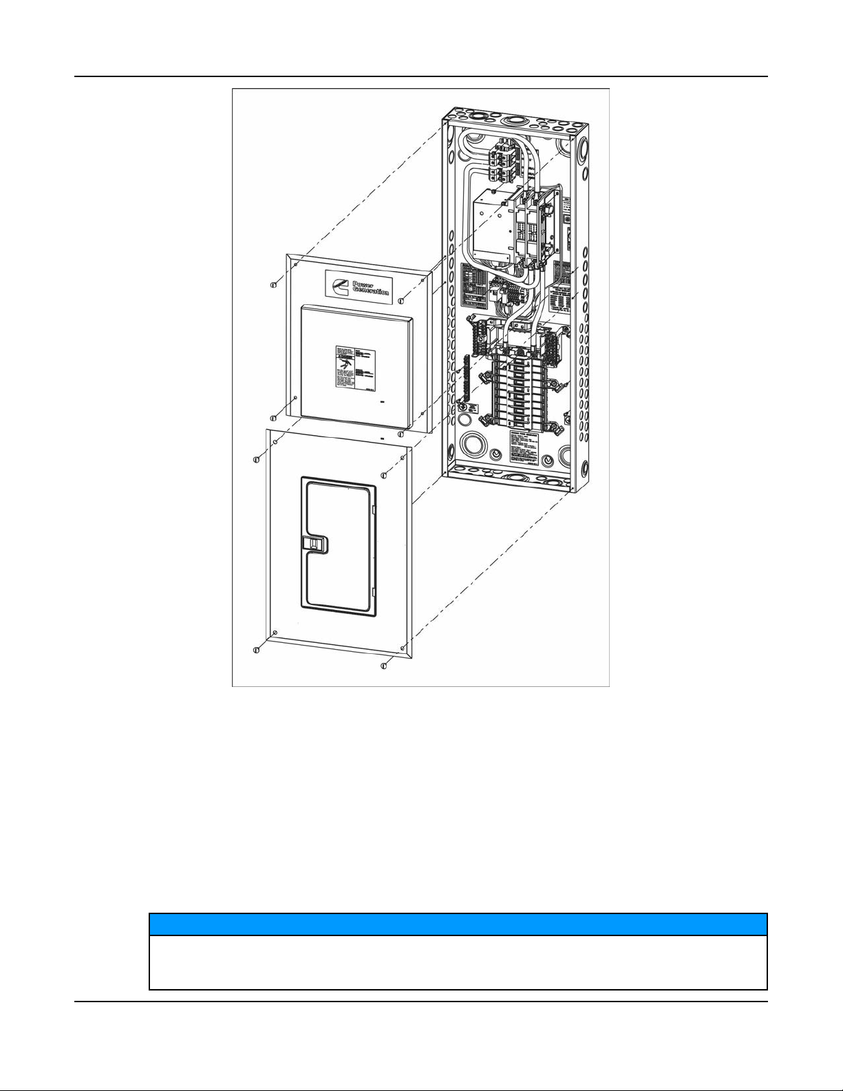
FIGURE 1. RA112L1 AUTOMATIC TRANSFER SWITCH
2.2 Transfer Switch Application
Transfer switches are an essential part of a building's standby or emergency power system. The utility line
(normal power), is backed up by a generator set (emergency power). The transfer switch connects the
electrical load to the utility or generator set.
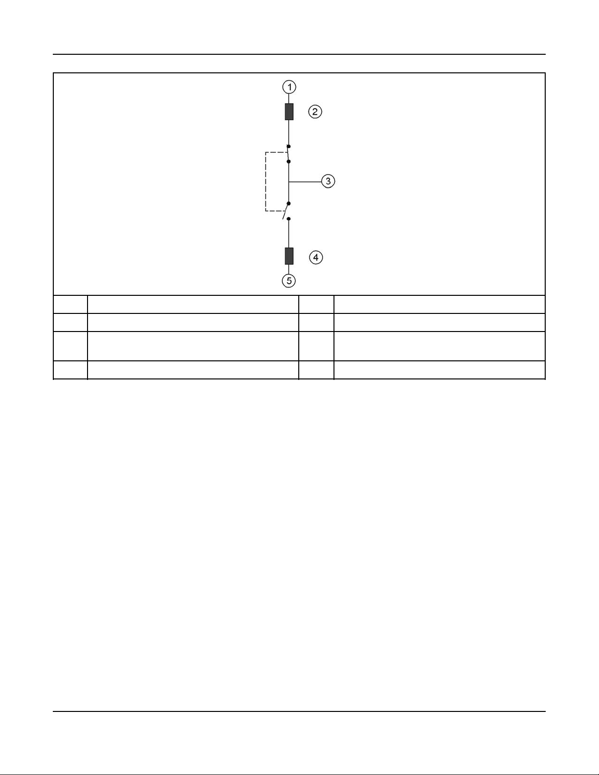
The load is connected to the common of the automatic transfer switch, as shown below. Under normal
conditions, the load is supplied with power from the utility (as illustrated). If utility power is interrupted, the
load is transferred to the generator set. When utility power returns, the load is retransferred to the utility.
The transfer and retransfer of the load are the two most basic functions of a transfer switch.
NOTICE
Maximum continuous loads not to exceed 80% of the overcurrent protective device (circuit
breaker and fuses) ratings employed in other than motor circuits, except for those circuits
employing circuit breakers marked as suitable for continuous operation at 100% of their ratings.
6 A052S254 (Issue 2)Copyright © 2016 Cummins Inc.
No. Description No. Description
2. Introduction10-2016
1 Utility (Normal Power) 4 Over Current Protective Device
2 Over Current Protective Device (Customer
Supplied)
3 Load
FIGURE 2. LOAD TRANSFER SWITCH (TYPICAL FUNCTION)
5 Generator Set (Emergency Power)
2.3 Transfer Switch Function
Automatic transfer switches, capable of automatic operation without operator intervention, perform the
basic function of transferring the load to the available power source.
This automatic transfer switch, capable of automatic operation without operator intervention, is designed
for utility-to-generator applications. In utility-to-generator applications, the transfer switch performs the
following functions:
1. Senses the interruption of utility power
2. Sends a utility unavailable signal to the generator set
3. Receives transfer command from generator set control
4. Transfers the load to the generator set
5. Senses the return of utility power
6. Sends utility available signal to generator set
7. Receives retransfer command from generator set control
8. Retransfers the load to the utility
The transfer switch design is intended to signal when the utility voltage is not present and when it returns.
The utility sense relay coil will energize or stay energized at voltages other than nominal. Therefore, the
unit should not be expected to signal a failed utility to the generator set during undervoltage or overvoltage
conditions.
7A052S254 (Issue 2) Copyright © 2016 Cummins Inc.

2. Introduction 10-2016
2.4 Model Identification
The model number, serial number, and electrical characteristics are shown on the nameplate. The
nameplates for the RA Series transfer switches are located on the inner back of the enclosure near the
bottom. Refer to the table below for the meaning of the model number characters.
TABLE 1. RA SERIES TRANSFER SWITCH MODEL CHARACTER KEY
Character Type Character(s)
Used
Series Name 2 RA
Amperage 1 1
Phase 1 1
Poles 1 2
Configuration 1 L
Enclosure Type 1 1
The example below is the designation for the RA112L1 model:
• RA switch series
• 1 - Amps (1-100, 2-200, etc.)
• 1 - Phase (1-single, 3-3phase)
• 2 - Number of poles
• L - Configuration (S - service entrance, N - non service entrance, L - load center)
• 1 - NEMA rating on box (1-1, 3-3R)
When contacting a distributor regarding the transfer switch, always give the complete model and date
code. This information is necessary to properly identify the unit among the many types manufactured. See
the How to Obtain Service section for more information.
Specification
2.5 How to Obtain Service
When a product requires servicing, contact your nearest Cummins Power Generation service provider
(power.cummin.com/sales-service-locator). When contacting a service provider, always supply the
complete model (RA112L1).
To contact your local Cummins Power Generation (CPG) distributor in the United States or Canada, call 1800-888-6626 and select Option 1. You will be connected to the distributor nearest your area code.
If you are unable to contact a distributor using the automated service, consult the Yellow Pages. Typically,
our distributors are listed under:
• Generators-Electric,
• Engines-Gasoline or Engines-Diesel,
• Recreational Vehicles-Equipment, or
• Parts and Service
When contacting a distributor regarding the transfer switch, always give the complete model (RA112L1).
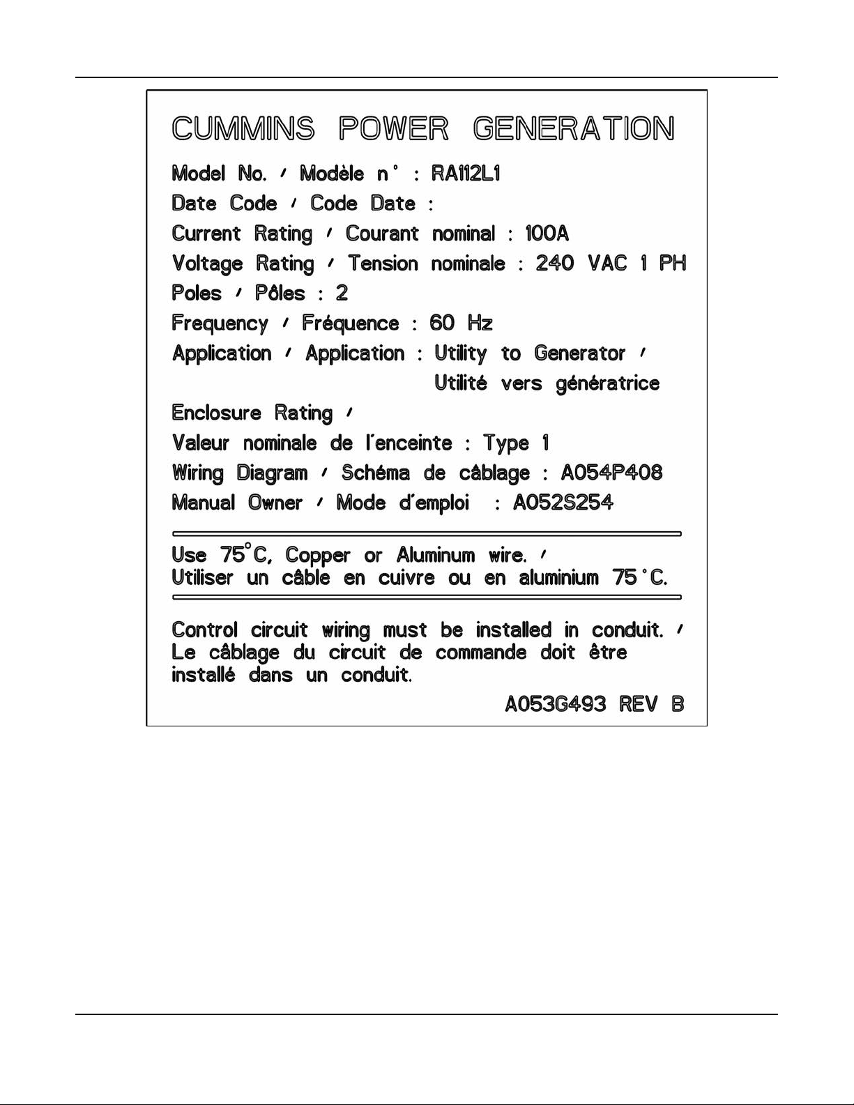
A model and date code label (shown below) is located on the on the inner back of the enclosure near the
bottom.
8 A052S254 (Issue 2)Copyright © 2016 Cummins Inc.
2. Introduction10-2016
FIGURE 3. MODEL AND DATE CODE LABEL
2.6 Application and Installation
Installations must be carefully planned and correctly installed for proper operation. This involves two
essential elements: application and installation.
Application refers to the design of the complete standby power system that usually includes power
distribution equipment, generator sets, transfer switches, mounting pads, and fuel systems. Each
component must be correctly designed so the complete system functions as intended. Application and
design is a technical function generally done by trained specialists. These specialists are responsible for
the design of the complete standby system and for selecting the materials and products required.
9A052S254 (Issue 2) Copyright © 2016 Cummins Inc.

2. Introduction 10-2016
Installation refers to the actual set-up and assembly of the standby power system. The installers set up
and connect the various components of the system as specified in the system design plan. The installation
of the standby system normally requires the special skills of qualified electricians, plumbers, sheet metal
workers, etc. to complete the various segments of the installation. This is necessary so all components are
assembled using standard methods and practices. Permits are also generally required. Be sure to have
your installation inspected by the local authority that has jurisdiction.
10 A052S254 (Issue 2)Copyright © 2016 Cummins Inc.
 Loading...