

CUMMINS PX7500, PX7500e Service Manual

SERVICE MANUAL
COMMERCIAL GENERATOR
PPXX77550000 && PPXX77550000ee
0914-0505 REV 11/06

CONTENTS
Section Title Page
1. SPECIFICATIONS....................................................................................................... 1
2. PERFORMANCE CURVES ........................................................................................... 2
3. FEATURES.................................................................................................................. 3
3-1 A.V .R. AL TERNA T OR ............................................................................................ 3
3-2 OIL SENSOR ........................................................................................................3
3-3 QUIET OPERATION .............................................................................................3
3-4 NO RADIO NOISE ................................................................................................3
3-5 LARGE FUEL TANK.............................................................................................. 3
3-6 RUGGED TUBULAR FRAME ............................................................................... 3
3-7 MINIMAL MAINTENANCE ....................................................................................3
3-8 LONG-LIFE DURABILITY ..................................................................................... 3
4. GENERAL DESCRIPTION.......................................................................................... 4
4-1 EXTERNAL VIEW .................................................................................................4
4-2 CONTROL PANEL ................................................................................................ 5
4-3 LOCATION of SERIAL NUMBER and SPECIFICATION NUMBER ...................... 6
5. CONSTRUCTION AND FUNCTION ........................................................................... 7
5-1 CONSTRUCTION ................................................................................................. 7
5-2 FUNCTION............................................................................................................ 7
5-3 DESCRIPTION of GENERATOR OPERATION .................................................. 11
5-4 OIL SENSOR ......................................................................................................14
6. SAFETY PRECAUTIONS ......................................................................................... 17
7. RANGE OF APPLICATIONS .................................................................................... 18
8. MEASURING PROCEDURES .................................................................................. 21
8-1 MEASURING INSTRUMENTS ........................................................................... 21
8-2 AC OUTPUT MEASURING................................................................................. 24
8-3 DC OUTPUT MEASURING................................................................................. 24
8-4 MEASURING INSULATION RESISTANCE ........................................................ 25
9. CHECKING FUNCTIONAL MEMBERS.................................................................... 27
9-1 VOLTMETER.......................................................................................................27
9-2 AC RECEPT ACLES ............................................................................................ 27
9-3 No-FUSE BREAKER........................................................................................... 27

Section Title Page
9-4 STATOR .............................................................................................................. 28
9-5 ROTOR ASSEMBLY ........................................................................................... 28
9-6 BRUSH................................................................................................................ 29
9-7 A.V.R. (AUTOMATIC VOLTAGE REGULATOR)..................................................29
9-8 DIODE RECTIFIER............................................................................................. 31
9-9 OIL SENSOR ......................................................................................................32
9-10 EXCITING COIL................................................................................................ 32
10. DISASSEMBL Y AND ASSEMBLY .......................................................................... 33
10-1 PREPARATION and PRECAUTIONS............................................................... 33
10-2 DISASSEMBLY PROCEDURES.......................................................................34
10-3 ASSEMBL Y PROCEDURES ............................................................................. 42
10-4 CHECKING, DISASSEMBLY and REASSEMBLY of the FRONT PANEL ........ 48
11. TROUBLESHOOTING ............................................................................................ 50
11-1 NO AC OUTPUT................................................................................................ 50
11-2 AC VOLTAGE IS TOO HIGH OR TOO LOW..................................................... 51
11-3 AC VOLTAGE IS NORMAL AT NO-LOAD,
BUT THE LOAD CANNOT BE APPLIED..................................... 52
11-4 NO DC OUTPUT ............................................................................................... 53
12. WIRING DIAGRAM ................................................................................................. 54
NOTE : As for the servicing information on engine po rtion, please refer to the EH41 engine
service manual

1. SPECIFICATIONS
ledoM 0057XP
epyT esahPelgniS,eloP-2,gniticxEfleS,hsurB
ycneuqerF zH05 zH06
r
o
t
CA
a
n
r
e
t
l
A
epyT enignEenilosaGevlaVdaehrevO,elcyC-4delooC-riA
ledoM D14HE
e
n
i
g
n
E
leuF enilosaGelibomotuA
egatloV
rotcaFrewoP 0.1
tuptuOCD )W001(A3.8-V21
tnemecalpsiD mc404
tuptuOdetaR mpr0063/PH5.9
tuptuOmumixaM W0036 W0037
tuptuOdetaR W0055 W0006
detaR
tnerruC
rotalugeRegatloV epyT.R.V.A
yticapaCknaTleuF sretil5.72
noitarepOsuounituoCdetaR
,V022,V011
,V042,V032
V022/V011
sruoh0.9.xorppA sruoh0.7.xorppA
,V021,V011
,V022/V011,V022
V042/V021
3
yticapaCliO sretil2.1
metsySgnitratS retratScirtcelElanoitpOdnaretratSlioceR
)HxWxL(snoisnemiD mm035x035x096
thgieWyrD *)gk59(gk09
* Electric starter motor is available as option.
-1-
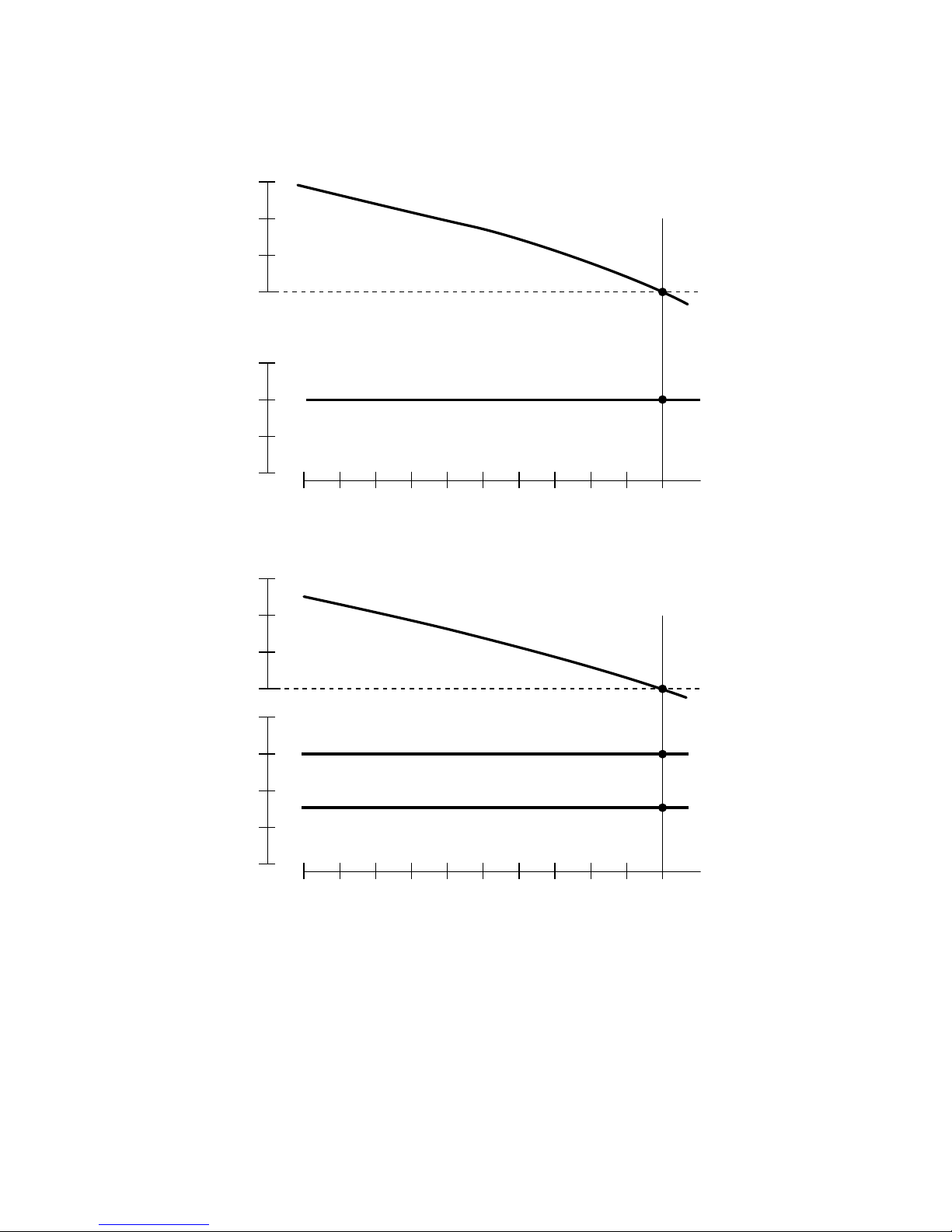
2. PERFORMANCE CURVES
60Hz
(Hz)
63
62
61
60
(V)
250
(
)
125
240
(
)
120
230
(
)
115
220
(
)
110
0 1/2 4/4
50Hz
(Hz)
53
Hz
240V/120V
Load Rated
DC OUTPUT
DC Voltage................. 12 V
DC Ampere ................ 8.3 A
(V)
250
(
125
240
(
120
230
(
115
220
(
110
210
(
105
52
51
50
Hz
)
240V
)
)
)
)
0 1/2 4/4
220V/110V
Load Rated
DC output................... 100 W
The voltage curve shown in the left indicates the characteristic of DC output when charging a battery.
The voltage may be decreased by 20% when the resistance load is applied.
NOTE : It is possible to use both DC and AC outputs simultaneously up to the rated output in total.
- 2 -

3. FEATURES
3-1 A VR ALTERNATOR
Output votage becomes more stable due to A.V.R. system and water proof (1P23 level) / brush type
alternator ensures trouble free operation.
3-2 OIL SENSOR
Oil sensor automatically shuts off the engine whenever the oil level falls down below the lower limit to
protect the engine from seizure.
3-3 QUIET OPERATION
Cummins Onan PX7500 generator delivers a quiet operation with :
* High performance 4-stroke Cummins Onan OHV engine.
* Extra large muffler and large air cleaner provide remarkable quiet operation.
3-4 NO RADIO NOISE
Noise suppressor spark plug is equipped standard to prevent radio frequency interference.
3-5 LARGE FUEL TANK
Extra large fuel tank (27.5 L) allows more than 9 hours/ 50 Hz (7 hours/ 60 Hz) of continuous operation
which is sufficient for a half day or one day work without refueling.
3-6 RUGGED TUBULAR FRAME
Full cradle type rugged tubuler frame protects the generator all around.
3-7 MINIMAL MAINTENANCE
* A drip-proof alternator design.
* No-fuse circuit breakers.
* An electronic pointless ignition system.
3-8 LONG-LIFE DURABILITY
The heavy-duty 4 stroke Cummins Onan OHV engine :
* Full rubber mount in a sturdy tubular frame.
* A forged carbon steel crankshaft supported by two main ball bearings.
* A pointless electronic ignition system.
* A special cast-iron cylinder liner.
- 3 -
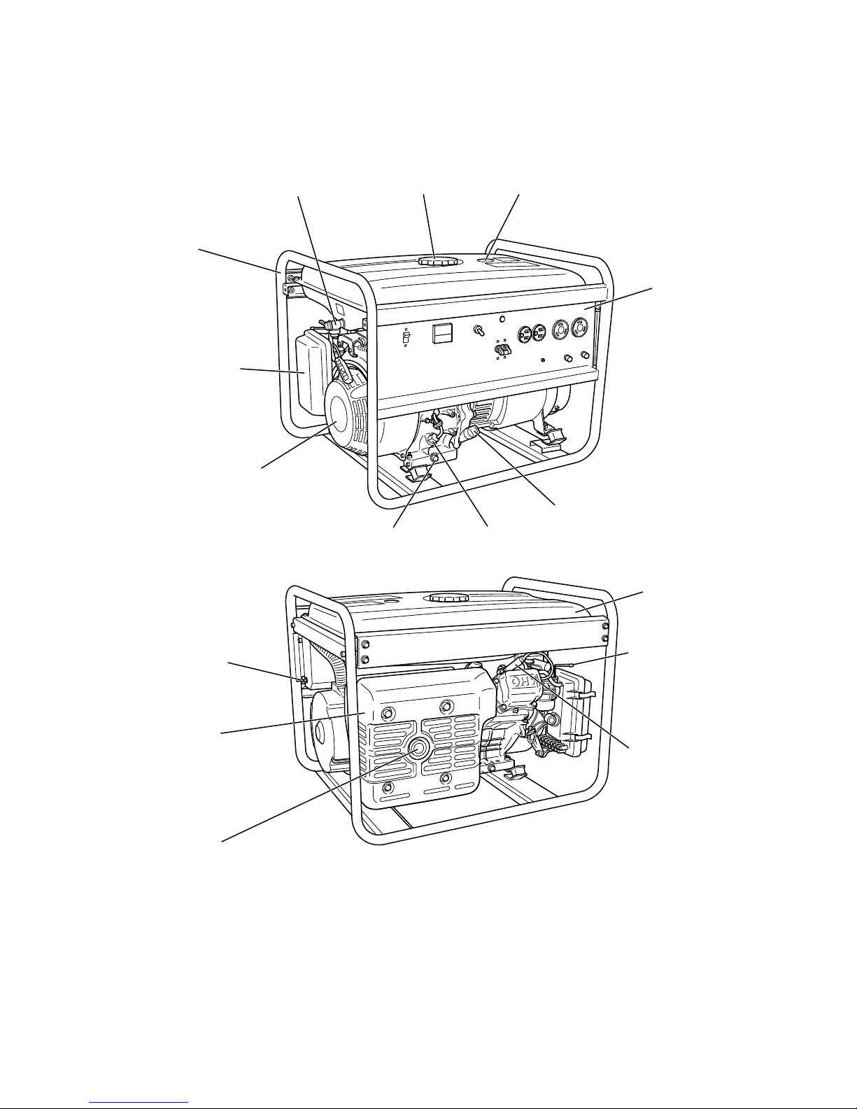
4. GENERAL DESCRIPTION
4-1 EXTERNAL VIEW
(
FUEL COCK
FRAME
AIR CLEANER
RECOIL STARTER
TANK CAPFUEL STRAINER
)
FUEL GAUGE
CONTROL
PANEL
OIL GAUGE (OIL FILLER)
OIL SENSOROIL DRAIN PLUG
FUEL TANK
EARTH
(
GROUND
TERMINAL
MUFFLER
COVER
EXHAUST
OUTLET
)
CHOKE LEVER
SPARK PLUG
CAP
- 4 -
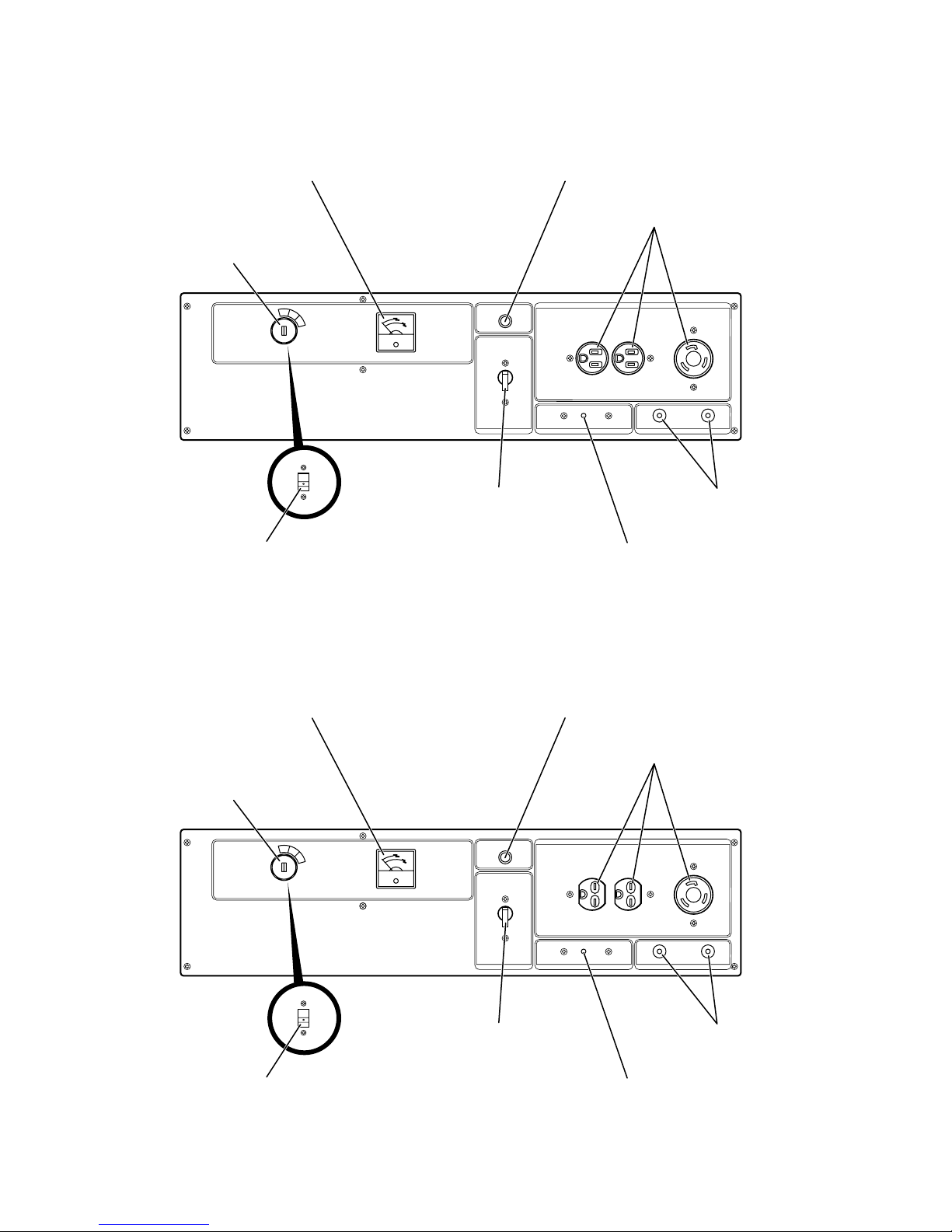
4-2 CONTROL PANEL
* 50Hz-110V, 60Hz-110V, 60Hz-120V
PILOT LAMPVOLTMETER
KEY SWITCH
(ELECTRIC
STARTER TYPE)
ENGINE SWITCH
(RECOIL STARTER TYPE)
* 50Hz-220V, 230V, 240V, 60Hz-220V
NO-FUSE BREAKER
AC RECEPTACLE
DC OUTPUT
TERMINAL
DC CIRCUIT BREAKER
VOLTMETER
KEY SWITCH
(ELECTRIC
STARTER TYPE)
ENGINE SWITCH
(RECOIL STARTER TYPE)
PILOT LAMP
NO-FUSE BREAKER
AC RECEPTACLE
DC OUTPUT
TERMINAL
DC CIRCUIT BREAKER
- 5 -
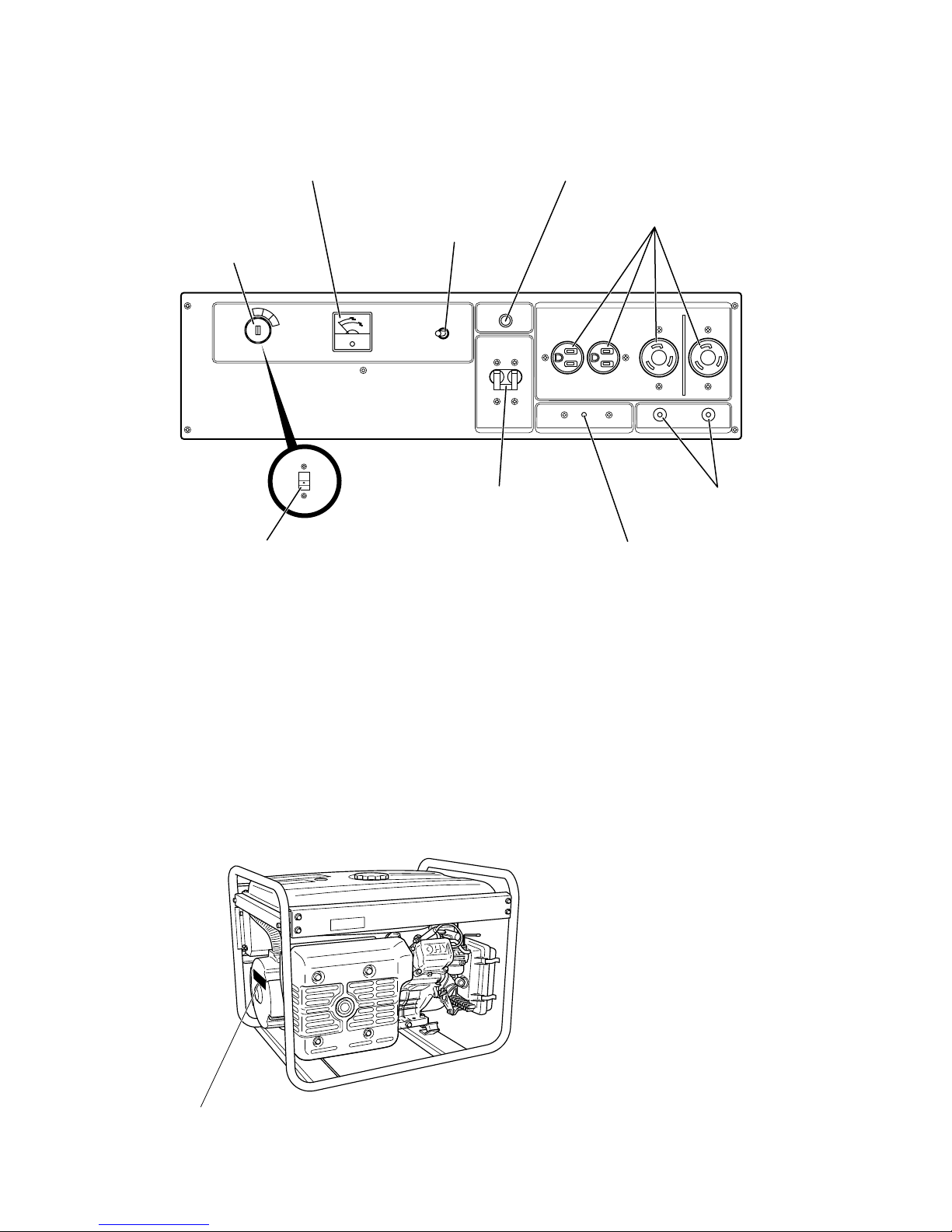
* 50Hz, 60Hz-110/220V, 60Hz-120/240V
VOLTMETER
KEY SWITCH
(ELECTRIC
STARTER TYPE)
ENGINE SWITCH
(RECOIL STARTER TYPE)
FULL POWER
SWITCH
NO-FUSE BREAKER
PILOT LAMP
AC RECEPTACLE
DC OUTPUT
TERMINAL
DC CIRCUIT BREAKER
4-3 LOCATION of SERIAL NUMBER and SPECIFICATION NUMBER
Serial number and specification number are stamped on the LABEL (MODEL NAME) stuck on the side
wall of rear cover.
NOTE : Always specify these numbers when inquiring about the generator or ordering spare parts in
order to get correct parts and accurate service.
LABEL, MODEL NAME
- 6 -
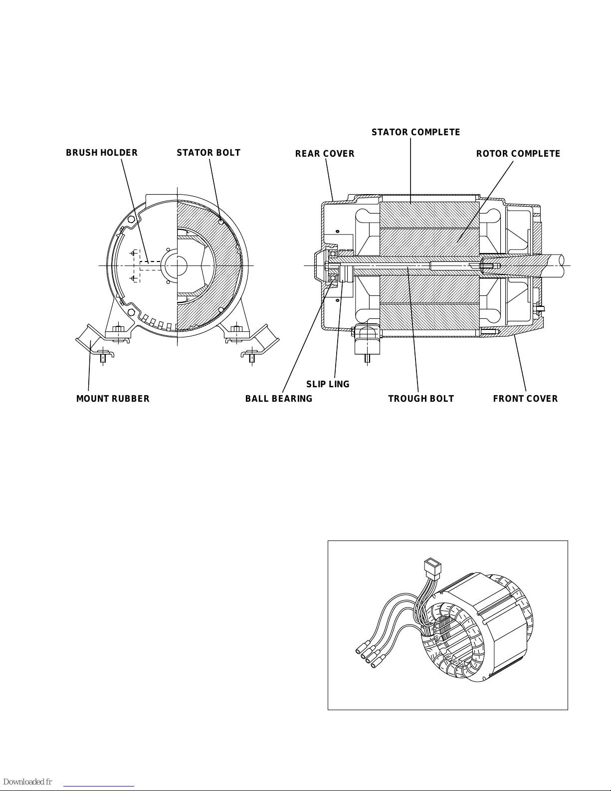
5. CONSTRUCTION AND FUNCTION
;;
;;
;;;
5-1 CONSTRUCTION
STATOR COMPLETE
BRUSH HOLDER
MOUNT RUBBER BALL BEARING TROUGH BOLT FRONT COVER
STATOR BOLT
REAR COVER ROTOR COMPLETE
SLIP LING
Fig. 5-1
5-2 FUNCTION
5-2-1 STATOR
The stator consists of a laminated silicon steel
sheet core, a main coil and a condenser coil which
are wound in the core slots.
The condenser coil excites the rotor field coil which
generates AC voltage in the main coil.
Fig. 5-2
- 7 -
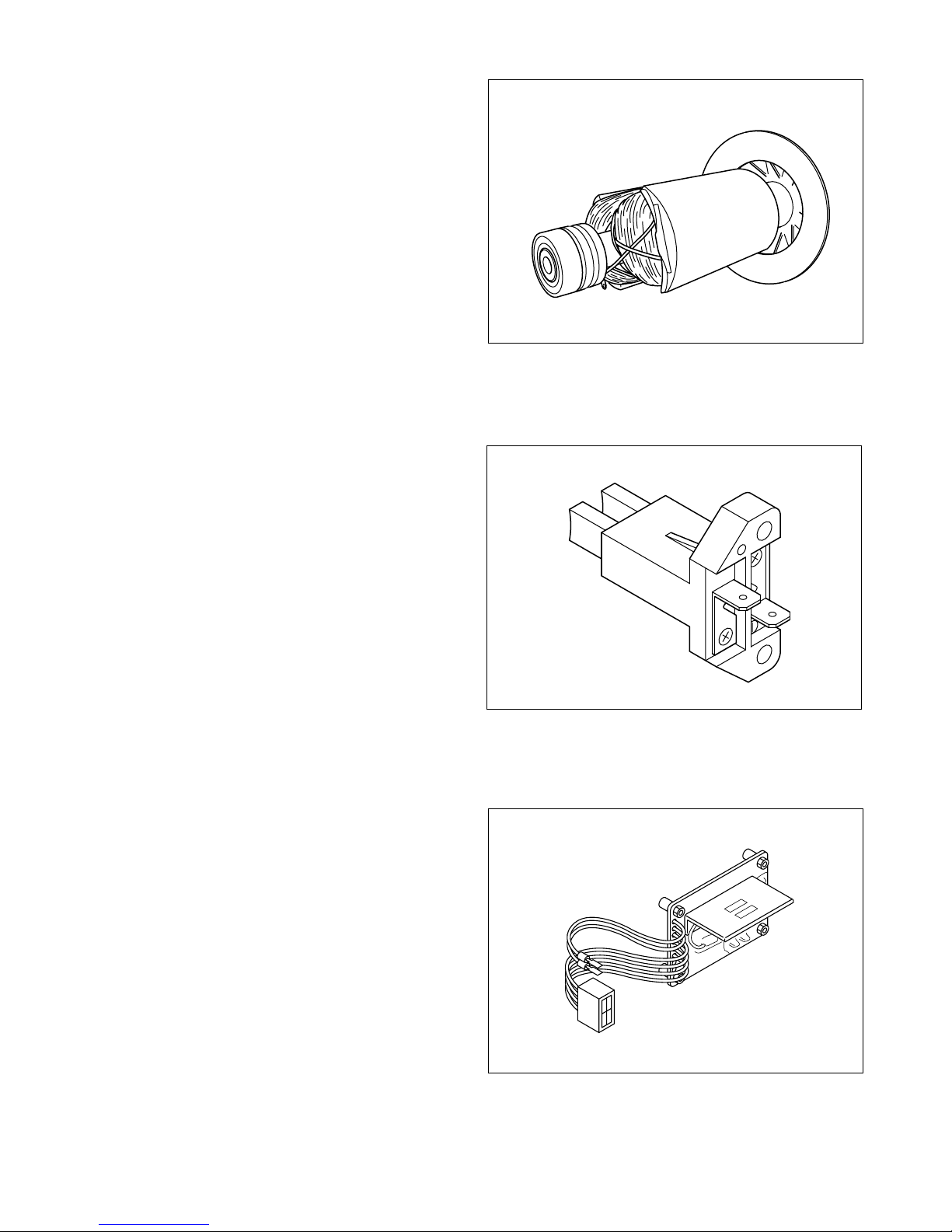
5-2-2 ROTOR
The rotor consists of a laminated silicon steel sheet
core and a field coil which is wound over the core.
DC current in the field coil magnetizes the steel
sheet core. T wo permanent magnets are provided
for the primary exciting action.
Slip rings are provided on the rotor shaft to receive DC exciting current from A.V.R..
5-2-3 BRUSH/ BRUSH HOLDER
An exciting current is supplied from the A.V.R to
the rotor. The brushes are made of carbon and
the brush-holder of plastic.
Fig. 5-3
It is necessary to keep the contact pressure between the brushes and slip rings within specific
limits. Thus, care must be taken of brush length.
5-2-4
A.V .R. (AUTOMA TIC VOL T AGE REGULA T OR)
The automatic voltage regulator employs an electronic circuit to automatically regulate voltage.
Fig. 5-4
Fig. 5-5
- 8 -
5-2-5 NO-FUSE BREAKER
The no-fuse breaker protects the generator from getting damage by overloading or short circuit in the
appliance. Table 5-1 shows the capacity of no-fuse breaker by each spec. and their object of protection.
NOITACIFICEPSREKAERBESUF-ONNOITCETORPfoTCEJBO
V022-zH05A52egarepmatuptuolatoT
V022-zH06A72egarepmatuptuolatoT
V042-zH05A32egarepmatuptuolatoT
V022/V011-zH05)tnemelE-2,eloP-2(A52egarepmatuptuolatoT
V022/V011-zH06)tnemelE-2,eloP-2(A72egarepmatuptuolatoT
V042/V021-zH06)tnemelE-2,eloP-2(A52egarepmatuptuolatoT
Table. 5-1
5-2-6 DC CIRCUIT BREAKER
The 10 ampere DC circuit breaker mounted on
the control panel protects whole DC circuit from
getting damage by overload or short circuit.
Fig. 5-6
- 9 -
TWIST
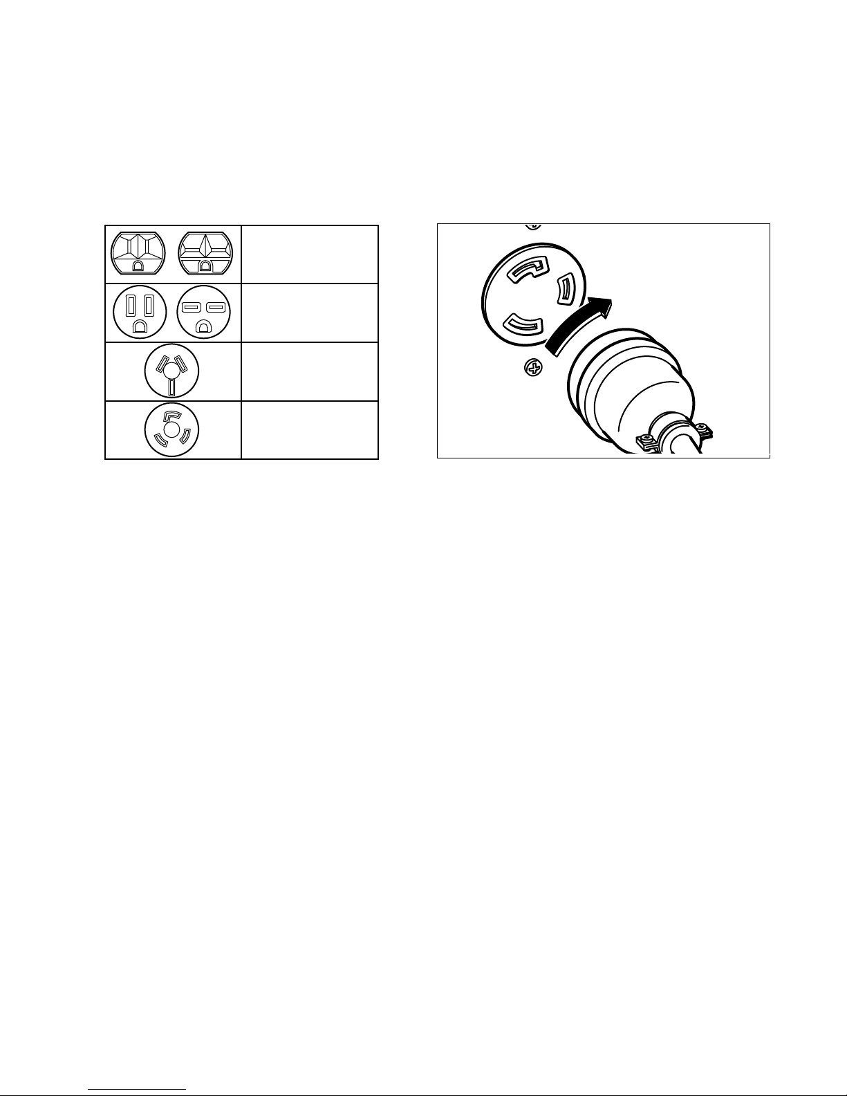
5-2-7 RECEPTACLE and AC PLUG
These are used for taking AC output power from the generator. A total of six kinds of receptacles, each
varying in rated voltage and current from another, are used. Each model has at least one receptacle to
deliver the rated generator output. As many AC plugs as the receptacles, each matching the corresponding receptacle, are provided. Table 5-2 shows the rated current for each receptacle. Be careful not to use
the receptacles and AC plugs beyond the specified amperage limits to prevent burning.
51latototpu
owtmorfserepma
selcatpecer
serepma51otpu
serepma02otpu
serepma03otpu
).noituaCeeS(
Table. 5-2
Caution : To connect the appliance to locking
receptacle, insert the plug into the receptacle and turn it clockwise to lock.
Fig. 5-7
NOTE : If your generator has receptacles peculiar to your country, Table 5-2 does not apply.
-
10
-
5-3 DESCRIPTION of GENERATOR OPERATION
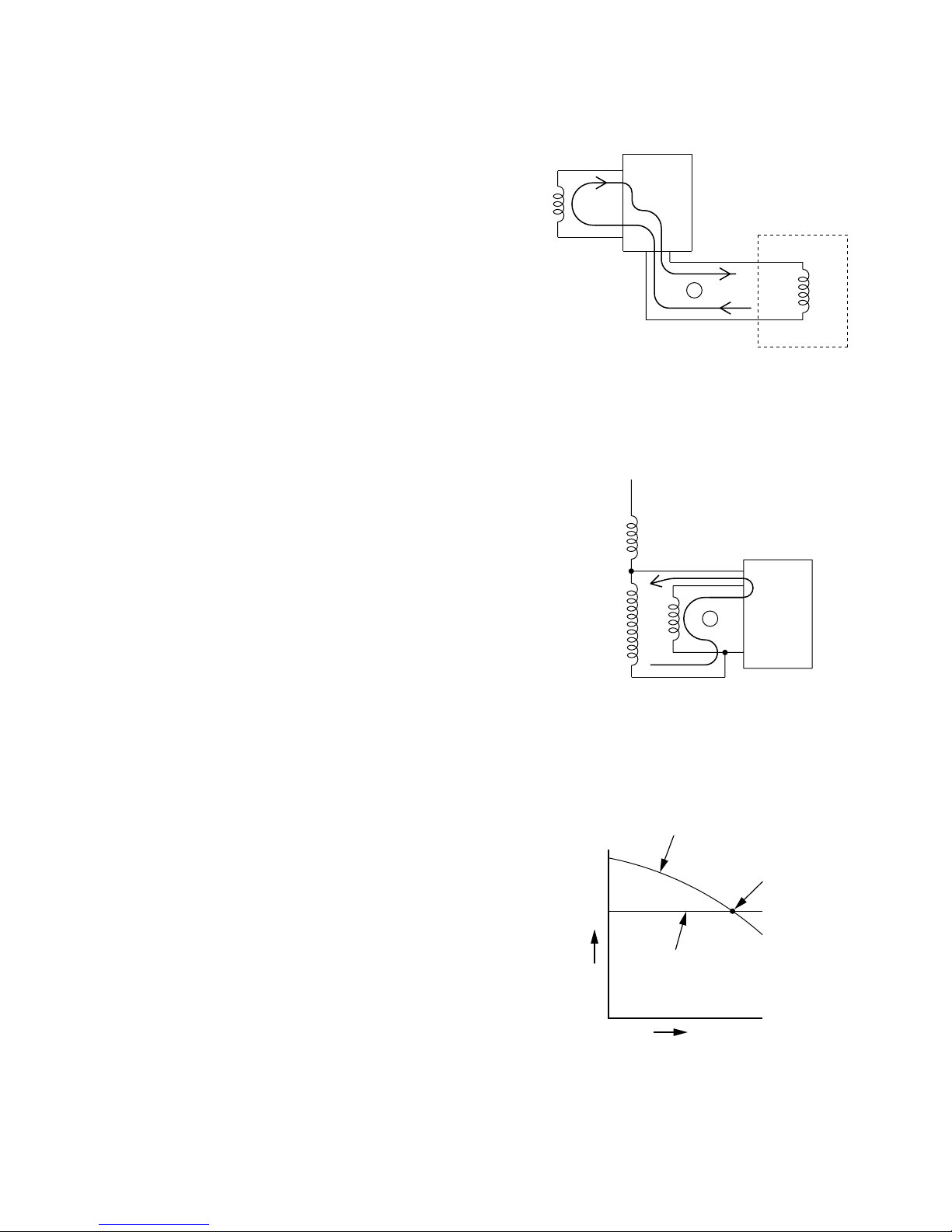
5-3-1 PRIMARY EXCITING ACTION
When the generator is started, the permanent
magnet on the engine rotates to generator a voltage in the exciting coil. This voltage is regulated
by a diode in the A.V.R. to feed a current to the
generator field coil. (FC). (See Fig. 5-8)
AVR
FC
The rotor is turned an electromagnet by that current and rotates so that voltage are generated in
the stator coils (main coil and sub coil). The voltage generated in the sub coils is operated by the
A.V.R. to feed a current to increase the field coil
current. (See Fig. 5-9)
As a result, the rotor magnetism increases.
This operation is repeated to generate the rated
voltage at 60 Hz in the main coil and DC coil.
5-3-2 VOLTAGE REGULATING MECHANISM
Connect a load to the AC output terminal and increase current. Output voltage varies as shown
in Fig. 5-10 depending on whether an automatic
voltage regulator is used or not.
The operation of the A.V.R. is explained below.
When an AC output is taken, the engine is loaded
and its rpm falls, Also the AC voltage fails due to
the voltage drop caused by the internal resistance
of the coils. The A.V.R. detects this voltage drop
and its built-in SCR automatically increase the
current flows to the field coil. As a result, the rotor
magnetism increase, the voltage fallen by the load
current is raised, and the output voltage is kept
constant. If the AC output is reduced, the SCR
operates in the opposite way to similarly keep the
output voltage constant.condenser coil. When
current a increases, the density of magnetic flux
across the rotor core rises. As a result, the current flowing in the field coil increases and the generator output voltage is prevented from decreasing.
MC
SC
WITHOUT AVR
V
a
Fig. 5-8
FC
Fig. 5-9
WITH AVR
A
Fig. 5-10
ENGINE MAGNETO
b
RATED VOLTAGE
AVR
EC
-
11
-
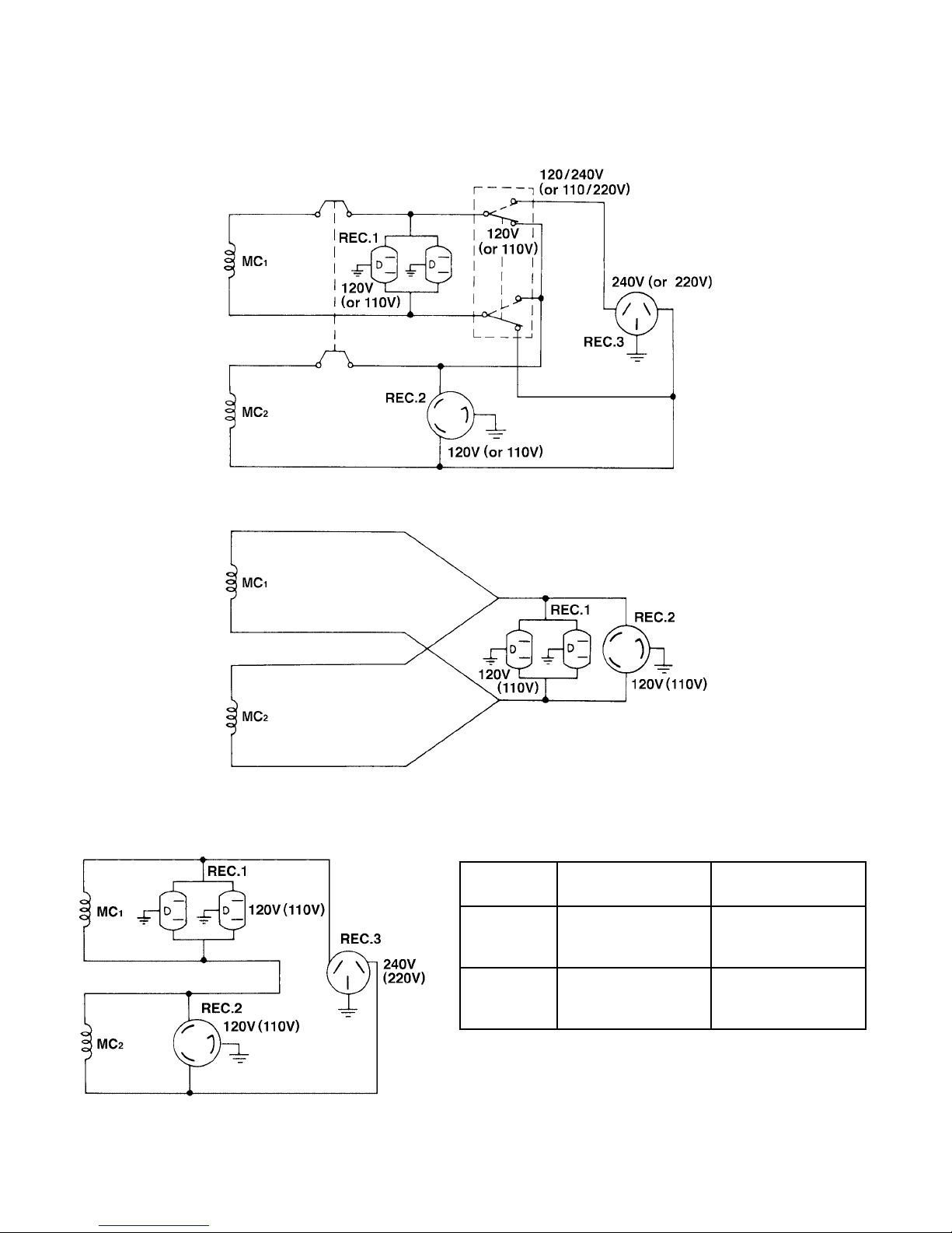
5-3-3 FULL POWER SWITCH (Dual Voltage Type)
The full power switch is provided for the dual voltage type to take out the full rated power from one
receptacle in each voltage.
Fig. 5-11
Fig. 5-13
Fig. 5-12
-
12
hctiwS
noitisoP
V011
ro
V021
V022/011
ro
V042/021
EGATLOVREWOL
ELCATPECER
tuptuodetaR
tuptuodetarfoflaHtuptuodetaR
EGATLOVREHGIH
ELCATPECER
ebnactuptuooN
.nekat
-

Two main coils are wound over stator core. Each main coil outputs half the rated power at the lower
voltage (110V or 120V). These main coils are wound to be in the same phase. The full power switch
reconnects these main coils in parallel or in series.
Fig. 5-11 shows a circuit diagram. When the full power switch is set for single lower voltage indication
(110V or 120V), the switch position is as indicated by the lower solid line in the diagram. Fig. 5-12 is a
simplified representation of this circuit, showing the two main coils connected in parallel. In this case, the
higher voltage (220V or 240V) at Rec. 3 cannot be taken out. Rec. 2 for the lower voltage can output up
to the rated power (up to 30A if the rated current is over 30A), and Rec. 1 can output up to a total of 15A.
When the full power switch is set for double voltage indication (110V/220V or 120V/240V), the switch
position is as indicated by the upper dotted line in Fig. 5-1 1. Fig. 5-13 is a simplified representation of this
circuit, showing the two main coils connected in series. In this case, power can be taken simultaneously
from the receptacles for the both voltages. Rec. 3 for the higher voltage can output up to the rated power,
but Rec. 1 and Rec. 2 for the lower voltage can output only up to half the rated power each.
Table 5-4 is a summary of the above explanation. Select the proper output voltage by full power switch in
accordance with the appliance to be used.
-
13
-

5-4 OIL SENSOR
OIL SENSOR
5-4-1 DESCRIPTION
* The oil sensor mainly functions to detect posi-
tion of the surface of engine oil in the crankcase
of engines for general use and to stop the engine automatically when the oil level goes down
below the lower limit specified. This prevents seizure of engine from occurring due to insufficient
amount of oil in the crankcase.
* Since the sensor has been designed to consume
a part of power supplied to the igniter to energize its electronics circuit, any other external
power supply is not necessary so that it can be
mounted at the oil filler port.
Introduction of newly developed sensing principle features super durability and no change with the
passage of time as it does not use any moving part.
Merits due to introduction of electrical conductivity detection are as follows ;
Fig. 5-14
1 It has resistance to mechanical shocks and property of no change with the passage of time as
sensing element consists simply of electrodes having no moving parts.
2 At the same time, it is capable of detecting the oil level stably as it is not influenced by engine
vibrations.
3 No error occurs due to foam and flow of the oil.
4 Influence against the ignition system or the electronics units can be neglected because an electric
current supplied to the sensor can be decreased.
5-4-2 PRINCIPLE OF SENSING OIL LEVEL
There is a great difference between electric resistance of air and that of oil. Since the resistance of air is
far higher than that of oil, more electric current passes through the oil than through the air, although
absolute value of the current is very small. The sensor detects this current difference and make use of it.
The sensor judges the oil quantity, by comparing a current flowing across a pair of electrodes (inner and
outer) with the reference, in such a way that if a current flows between the electrodes more than the
reference, sufficient oil is in the crankcase, on the other hand, if a current flows less than the reference,
oil is not sufficient. Since an electric current is flown to detect oil quantity, this is called the “electrical
conductivity detection” type of sensor. The oil level to be detected is determined by the length of electrodes and their mounting positions with the engine.
5-4-3 HOW IT OPERATES
[Power supply]
The sensor makes use of a part of primary power source for ignition of the engine (igniter) to drive the
sensor circuit. Power to the sensor can usually be derived from the “stop button” by branching wires out.
-
14
-
[Judgement of oil level]
When sufficient oil is in the crankcase, both of inner and outer electrodes are immersed in the oil through
which current flows across the electrodes. The sensor judges that oil in the crankcase is sufficient. When
oil level goes down and the inner electrode is exposed to the air due to consumption of oil, no current flow
between the electrodes as air is considered to be electrically nonconductive. The sensor in this case
judges that oil is insufficient.
[Decision of oil shortage]
Oil level at the electrodes may go down momentarily probably due to the engine being slanted or affected
by vibration even if a sufficient oil is in the crankcase. For that reason, the sensor has an electronic timer
circuit to prevent it from interpreting as short of oil when amount of oil is sufficient. The sensor has been
designed so that the engine is to be stopped only when oil-shortage is detected for 5 seconds uninterrupted. The timer employs an integration circuit and it is to be reset when the inner electrode is soaked in
the oil again before the sensor decides it as oil-shortage. The oil level where the sensor decides as oilshortage, when oil level goes down gradually, is called “threshold level”.
[Automatic stop of engine]
When the sensor decides as oil-shortage, it makes the engine to stop running automatically for protection of engine. Once the stopping circuit is activated, it keeps functioning until it confirms that the engine
has made a complete stop, then the circuit stops functioning automatically.
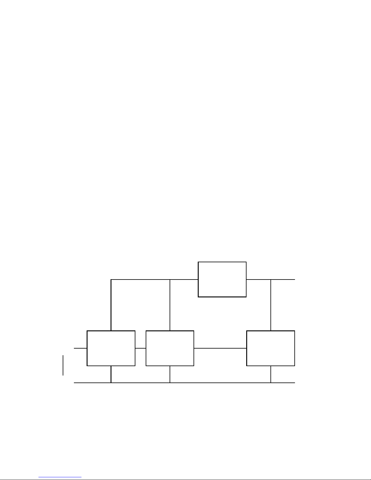
5-4-4 BLOCK DIAGRAM OF THE CIRCUIT
Power circuit
Detection
Inner pole
Oil
Outer pole Engine ground
Detection
circuit
circuit
Deley circuit
Fig. 5-15
Stopping
circuit
Igniter
1 Power circuit..........This rectifies a part of power to the igniter and regulates it to supply the stabi-
lized power to necessary circuits.
-
15
-

2 Detection circuit..... This detects quantity of oil, sufficient or not, according to difference of electric
resistance across inner and outer electrodes.
3 Delay circuit........... This prevents the sensor from making an unnecessary stop of the engine
by momentary lowering of the oil level due to the engine being slanted or
affected by vibration in spite of sufficient oil in the crankcase.
4 Stopping circuit...... This automatically stops the engine running.
5-4-5 CAUTIONS TO BE TAKEN ON HANDLING THE SENSOR
(1) Oil sensor unit
1 Be sure not to damage each wire. Broken or short-circuited power supply wires and/or a ground-
ing wire in particular may lead to malfunction or breakdown.
2 The sensor is not interchangeable from engine to engine because the sensor is to be exclusively
installed individually in each engine employed.
(2) Mounting and wiring of oil sensor unit
1 Although this has been designed to have enough antinoise properties in practical use, do not
route the sensor wirings in the vicinity of noise-generating sources such as ignition plugs or high
voltage cords. This may cause malfunction or breakdown.
2 Since capacity of power source is limited, current flown in the electronic circuit of the sensor is
kept as low as possible. Be sure to use terminals with a high contact reliability of more than that of
tinned terminals.
(3) Operation of oil sensor
1 If operating with the engine kept tilted, oil surface inside of the engine varies and the correct oil
level can not to be detected which in turn obstructs the preventing function of engine seizure.
Operate the engine by keeping it level.
2 When starting the engine with an insufficient oil in the crankcase, engine starts once then it stops
automatically after it runs for 5 seconds.
3 When the engine has been stopped by the oil sensor, voltage remained in the electronic circuit
prevents the sensor from being restarted for 3 seconds after the engine stop. Try to restart the
engine after 3 seconds or more.
-
16
-
 Loading...