

CUMMINS PS0500, PowerStart0500 Technical Training Participant’s Manual
Technical Training Participant’s Guide
- 1 -

PowerStart0500 Module
Table Of contents
Introduction.…………….……………………………………………..3
Overview………………...……………………………………………. 5
How to operate me……...……..…………………………………….7
PS0500 control features..…………………..……………………...25
Mounting Guidelines…….…………….………………………… . 28
Control outputs/inputs………………………………………..…...29
Control systems………….………………..…………………….….34
Setup Trims and adjustments……………………………............40
Meter Calibrations……………….…………………………….……44
Wiring diagram…….…………….…………………………….…….51
Environmental capability…………………………………….…….52
Faultcode list……………………………………………………..….53
Troubleshooting………………………………………………….…54
- 2 -

Introduction
Welcome! Welcome to the training module for the PowerStart 0500. This module was
written by the Cummins Sales and Service India Limited-Electronic Cell department for your use
and reference. We suggest you read through the entire Introduction to become familiar with the
module’s structure. Then, just follow along in the module during your training session.
Module Purpose
The purpose of the Power Start 0500 training module is to help you to understand the
Power Start 0500 which is going to be used on Low Horse Power (LHP) genset.
With this information, you will be better prepared to meet your customers’ varying needs.
Module Audience
This module was written for dealer service technicians who have previous experience with or
knowledge of electrical engine, and generator basics.
Module Structure
This module contains lessons on related topics. Each lesson follows a carefully designed training
format, including a warm up, presentation, and activity (or exercise).
Module Assessment
After completing all the lessons in the module, you will complete a module assessment. The
module assessment lets us evaluate the level of knowledge you have on the topic after
completing the module.
Module Comment Form
You will also complete a module comment form. This form gives you the chance to comment on
the usefulness and effectiveness of the training module and make suggestions for improvements.
We will use the results from the module assessment and module comment form to help us
determine if there is a need to modify the module.
- 3 -

Overview
The PS0500 controller is a microprocessor-based generator set monitoring, metering,
and control system. The control provides a simple operator interface to the Genset and engine
parameters, remote start / stop control and generator set protective functions. The control does
not have in-built speed governing and voltage regulation features. It does not support magnetic
pickup connectivity.
The PS0500 series controllers are designed for use on engines from 10 to 100 KW
range, it means it is genset controller without AVR controller in the range of 12.5KVA to 125KVA
for non-paralleling applications. The control can also be configured for various frequency (50 Hz /
60 Hz operation), voltage configuration up to 600 Vrms L-L. The control is designed for mounting
on the generator set.
The control also has a 16X2 LCD module with seven indicator LEDs and six tactile feel
pushbuttons, which can be used for navigation.
- 4 -
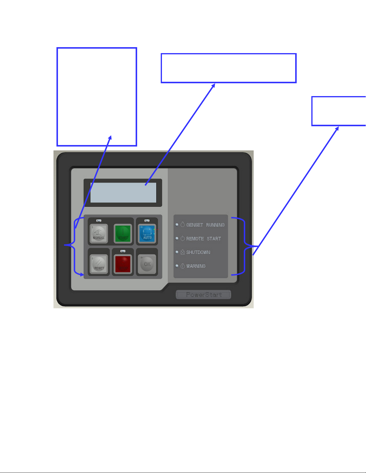
Tactile Push
Genset status
Buttons
•Manual
•Auto
•Start
16 X 2 Alphanumeric
display
•Stop
•Reset
•Ok
LEDs
- 5 -

Module assessment :
1) What is operating range of engine KVA rating for PS0500?
2) What are the functions of PS0500 controller?
3) Will PS0500 support voltage regulation?
4) What is maximum line to line RMS voltage reading configured in PS0500?
5) Can we get MPU support for PS000?
6) Can we start engine remotely by PS0500?
7) Will PS0500 support paralleling operation?
8) How many push buttons are uses in PS0500?
9) How many indicator LEDs are use in PS0500?
- 6 -
How to operate PS0500
The reason to include this module,is to make everyone aware of the product and its
operations.
One who will go through this will be very well educated about PS0500,its
operations,applications.
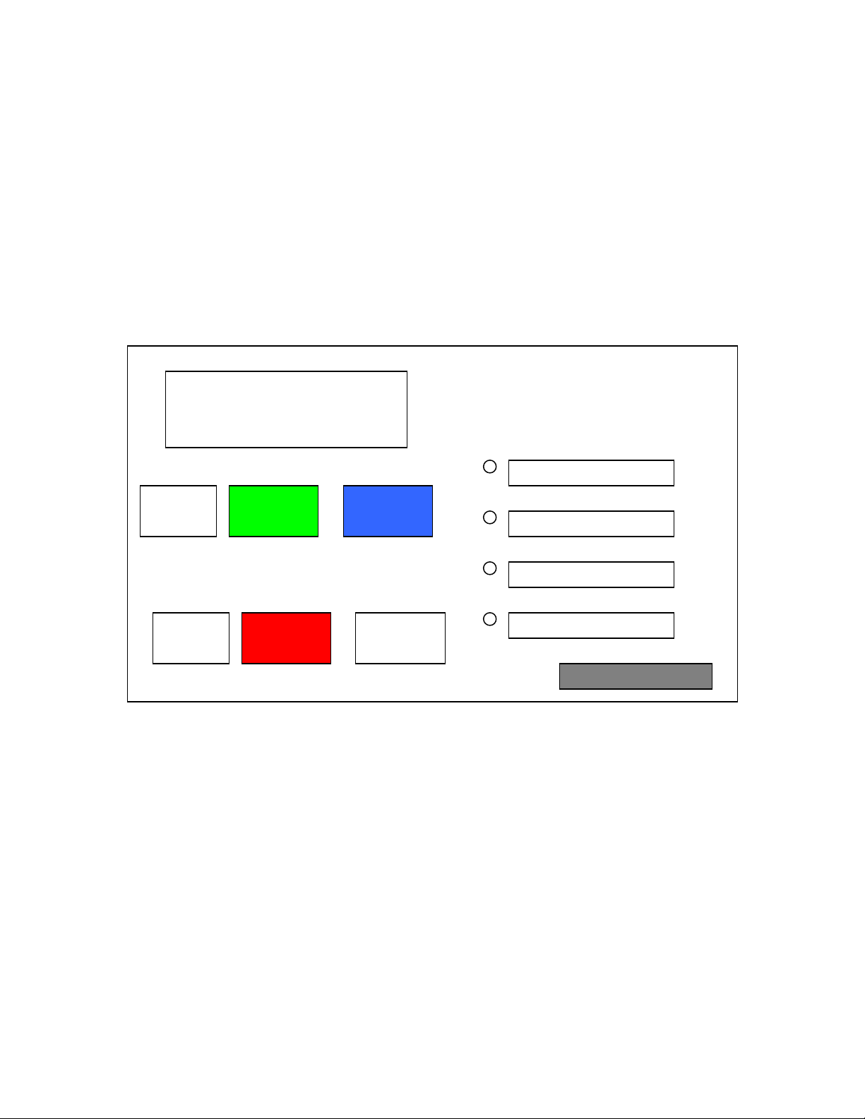
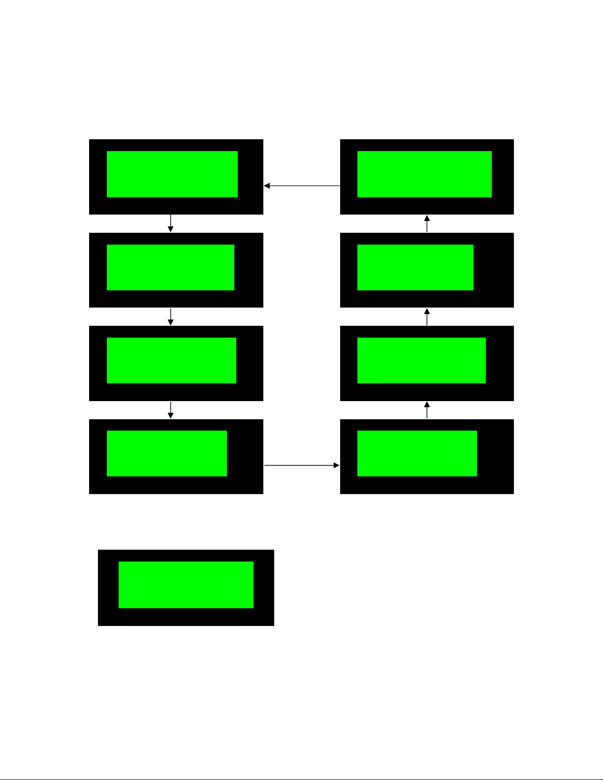
This is basic block diagram for PS0500,which will be refer throughout this module for
your reference.
PS0500
(16*2)
Manual
Reset Stop
LCD Display
Start Auto
OK
- 7 -
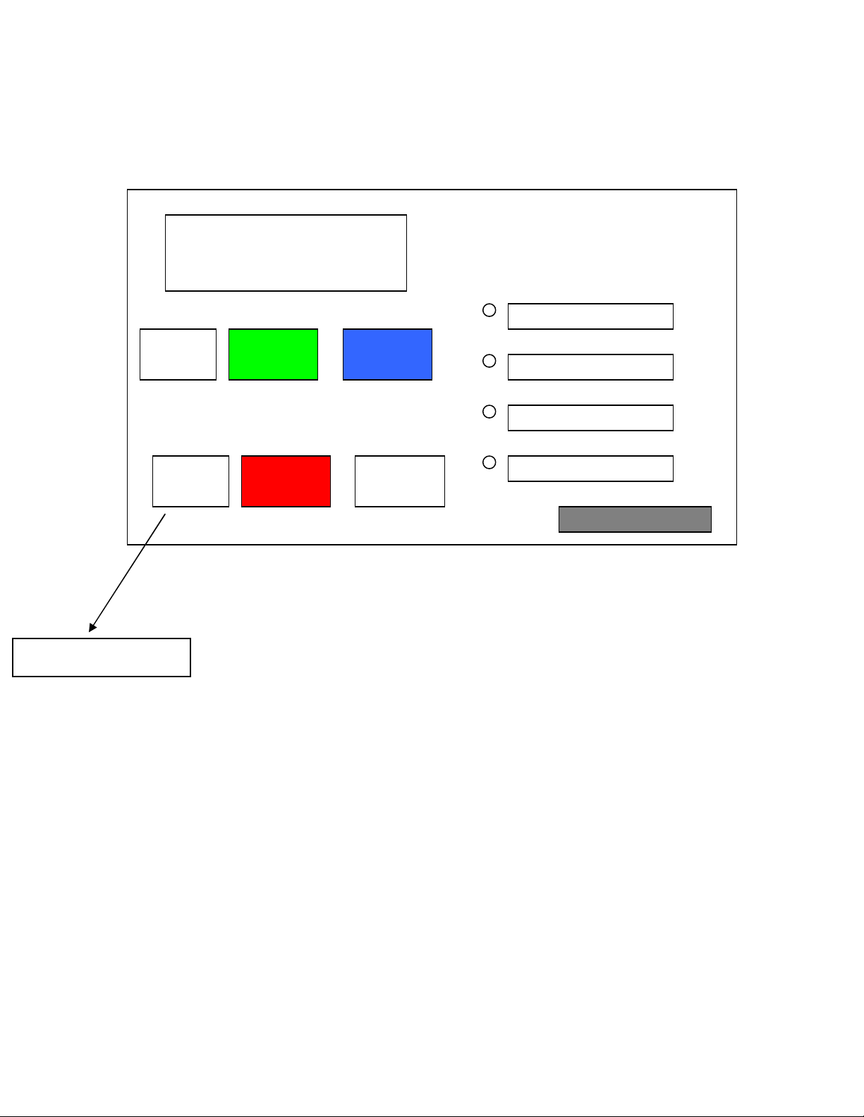
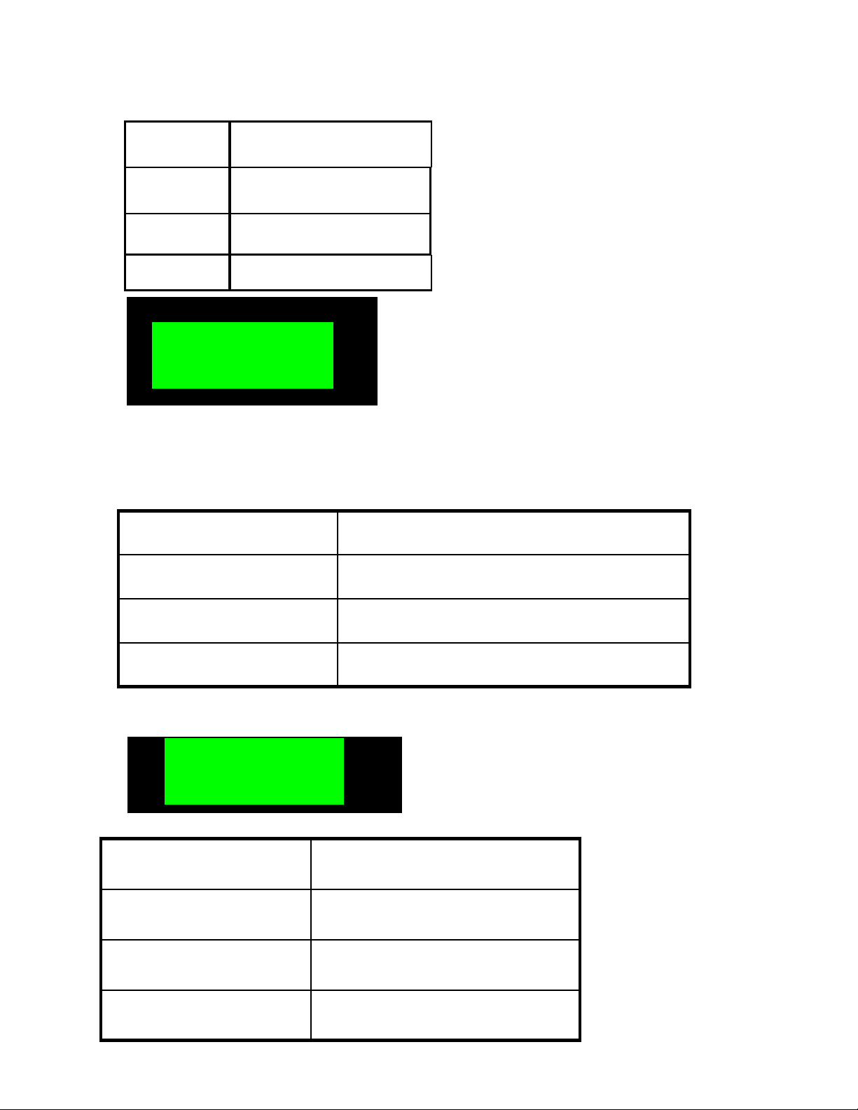
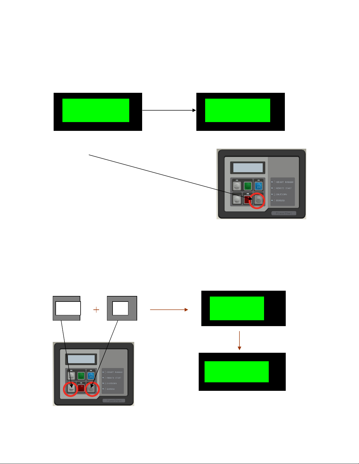
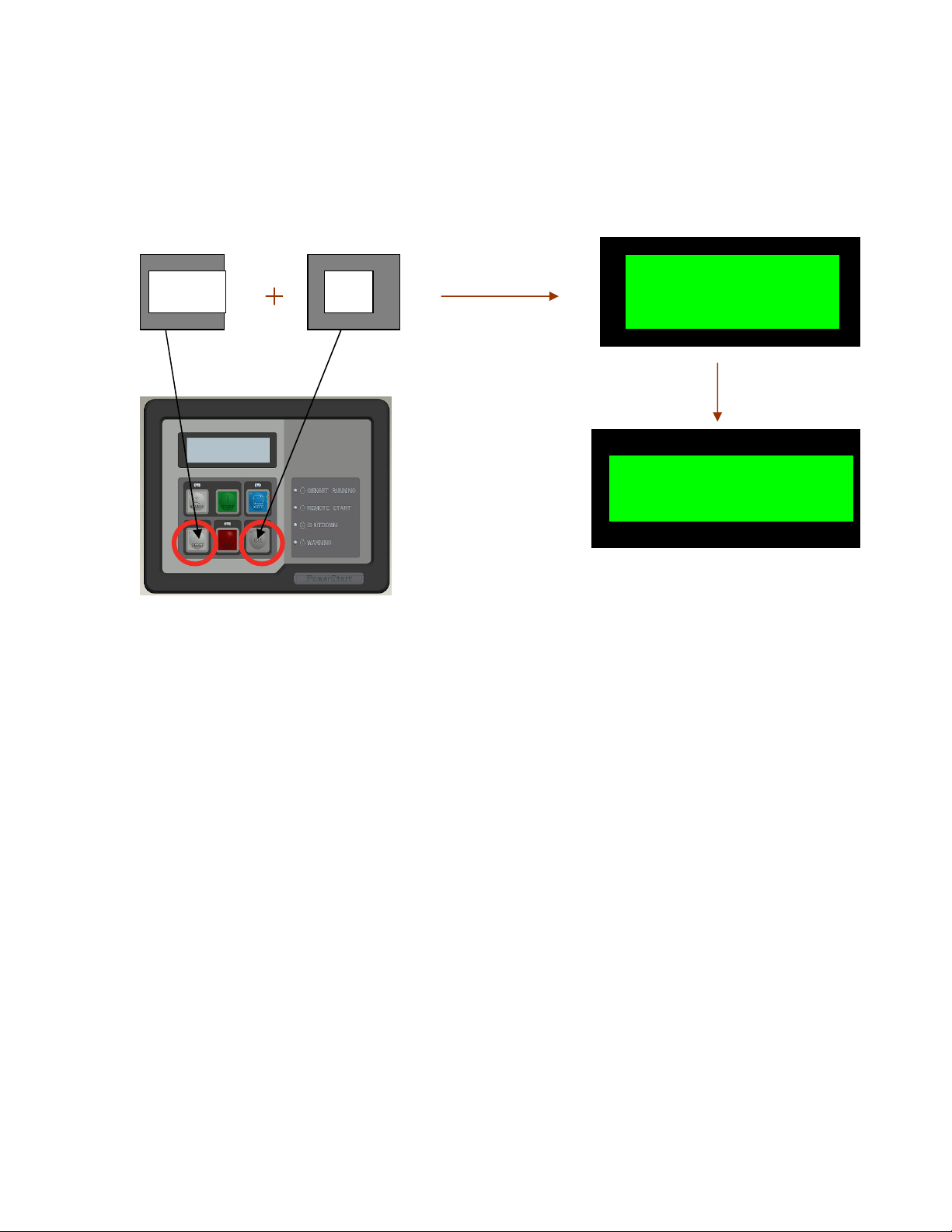
Lets first know how to start PS0500 after connecting it to 12V battery supply.
PS0500
BattVolts =------GensetHrs=------
Press this button
Once you press this push buttons all LED’s will glow for 1 second. And LED above
STOP button will start bblinking continuosly.While as on display show message shown
as in above picture.
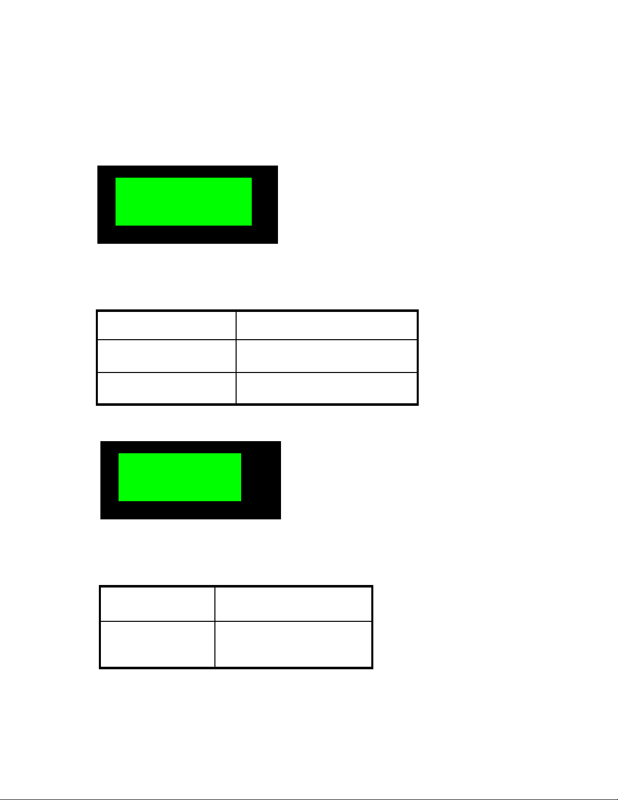
The display of PS0500 has three display mode-
1)Monitor
2)Set Up
3)Calibration
Monitor mode allows user to monitor the Genset parameters
Monitor mode has 2 modes of operations
Scroll - The display will scroll the screen one by
one
Scroll Stop – User can monitor a desired screen
continuously
Manual
Reset Stop
Start Auto
OK
- 8 -
2 sec
2 sec delay
2 sec
2 sec
2 sec delay
2 sec
2 sec delay
Current Flt=212
L1N=000 L2
N=000
L12=000 L23=000
E Stop=Inactive
I1=00.0 KVA=00.0
Batt Volts=11.7
KVA1 KVA2 KVA3
Oil Press=003PSI
L1N=000 L2 N=000
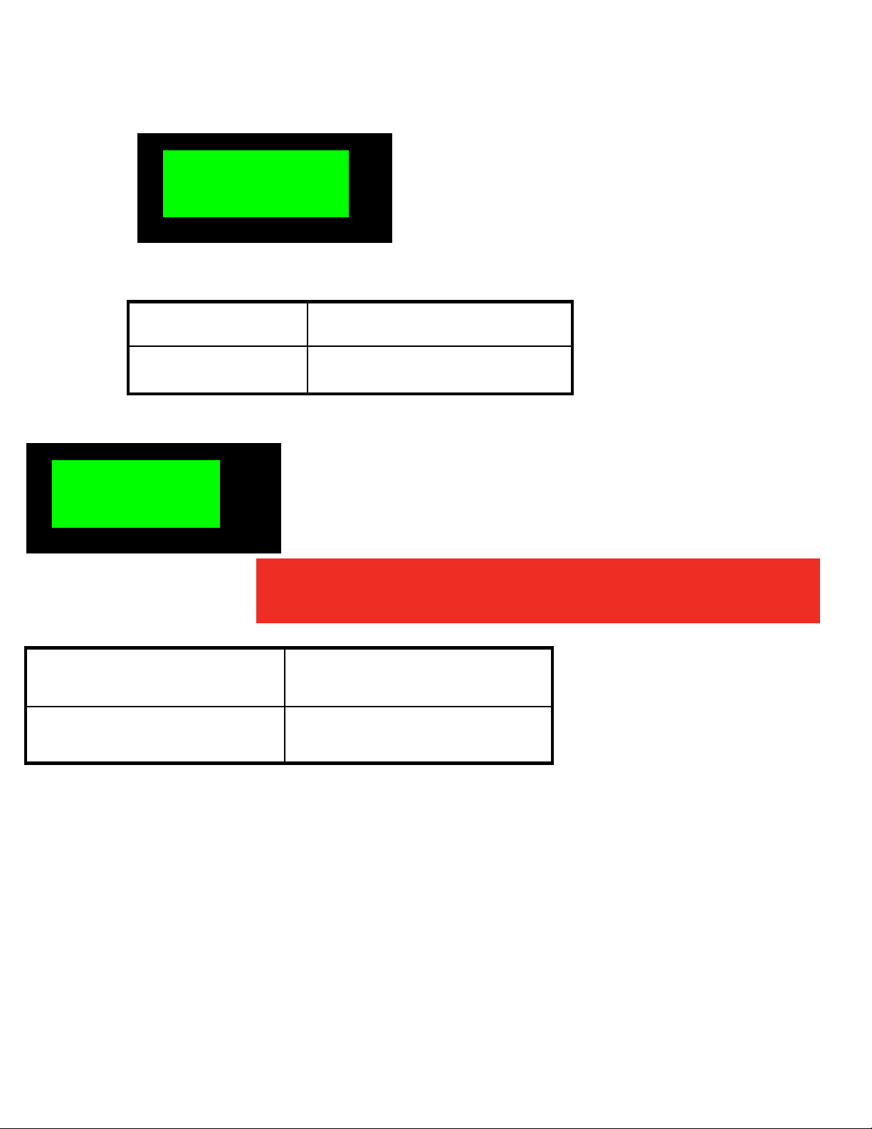
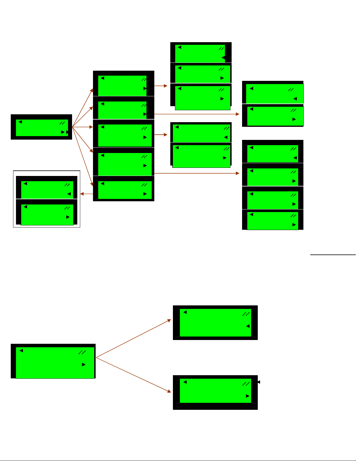
In scroll mode one will observe following screens,the screens will scroll in the time span
of 2 sec.
L3N=000 HZ=00.0
L13=000 HZ=00.0
delay
I2=00.0 I3=00.0
00.0 00.0 00.0
delay
Clnt TempOOR Wrn
Cust In=Inactive
delay
Genset Hrs=00000
delay
Clnt Temp=342F
Following is the explanation for all above screens.
Table
- 9 -
L3N=000 HZ=00.0
Table
L12=000 L23=000
Frequency
HZ
Line 2 to Line
3 Voltage
L23
Line 1 to Line 2 Voltage
L12
I1=0.0 KVA=00.0
Line 3 current
I3
Line 2 current
I2
Total power
KVA
Line 1 current
I1
L1N Line1 to Neutral Voltage
L2N Line2 to Neutral Voltage
L3N Line3 to Neutral Voltage
HZ Frequency
L13=000 HZ=00.0
L13
Line 1 to Line 3 Voltage
- 10 -
I2=00.0 I3=00.0
Table
KVA1 KVA2 KVA3
Line3 P
ower
KVA3
Line2 Power
KVA2
Line1 Power
KVA1
Table
Oil Press=003PSI
Coolant Temperature
Clnt Temp
Oil Pressure
Oil Press
00.0 00.0 00.0
Clnt Temp=342F
- 11 -
Table
Batt Volts=11.7
Genset Hours
Genset Hrs
Battery Voltage
Batt Volts
Table
E Stop=Inactive
Customer Input
Cust In
Emergency Stop
E Stop
Cust In=Inactive
Genset Hrs=00000
NOTE: E Stop and Cust In shows the status of the
input that whether it is active or inactive
- 12 -

Table
Current Flt=212
Coolant Temperature Out Of Range
Warning
Clnt Temp OOR Wrn
Current Fault
Current Flt
How to
enter
the Scroll Stop Monitor m
ode ?
Clnt Temp OOR Wrn
L1N=000 L2N=000
L3N=000 HZ=00.0
NOTE: It displays the type of the warning for
the fault condition
- 13 -
Press
Ok
button on front
How to
exit
from the Scroll Stop Monitor mode ?
OK
L1N=000 L2N=000
L12=000 L23=000
Ok
Press
Entering into the
Reset
SW PART 3267727
No Navigation is needed
Press Ok button to stop the scrolling and enter scroll stop to
monitor the parameters on specific screen continuously
L3N=000 HZ=00.0
L13=000 HZ=00.0
panel
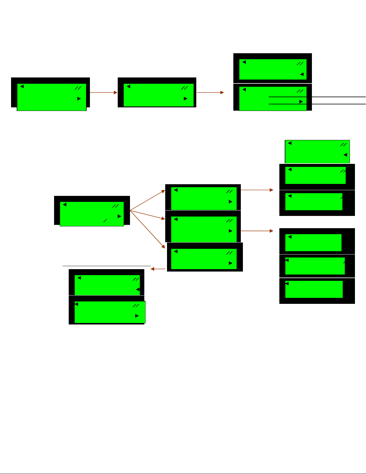
To enter into SETUP mode-
After going to stop mode only we can enter in to Setup mode.
For 5
Sec
- 14 -
Config Mode…
SW VER 1.01

*
Will go to the next value
Will go to the Previous value
Will go down
One need to understand key to operate-
Keys Properties
It shows the default value. when we select the particular
value it will comes to that value
Following are the screens of the display when you will enter setup mode.Use
above explain keys to go through and to change the value.
Jus look down for more clear understanding.
- 15 -

Main Menu
Main Menu
Main Menu
Main Menu
Main Menu
Main Menu
Alt SetUp
Units
Sensor Config
Customer I/O
Battle Shot
Flt History
- 16 -
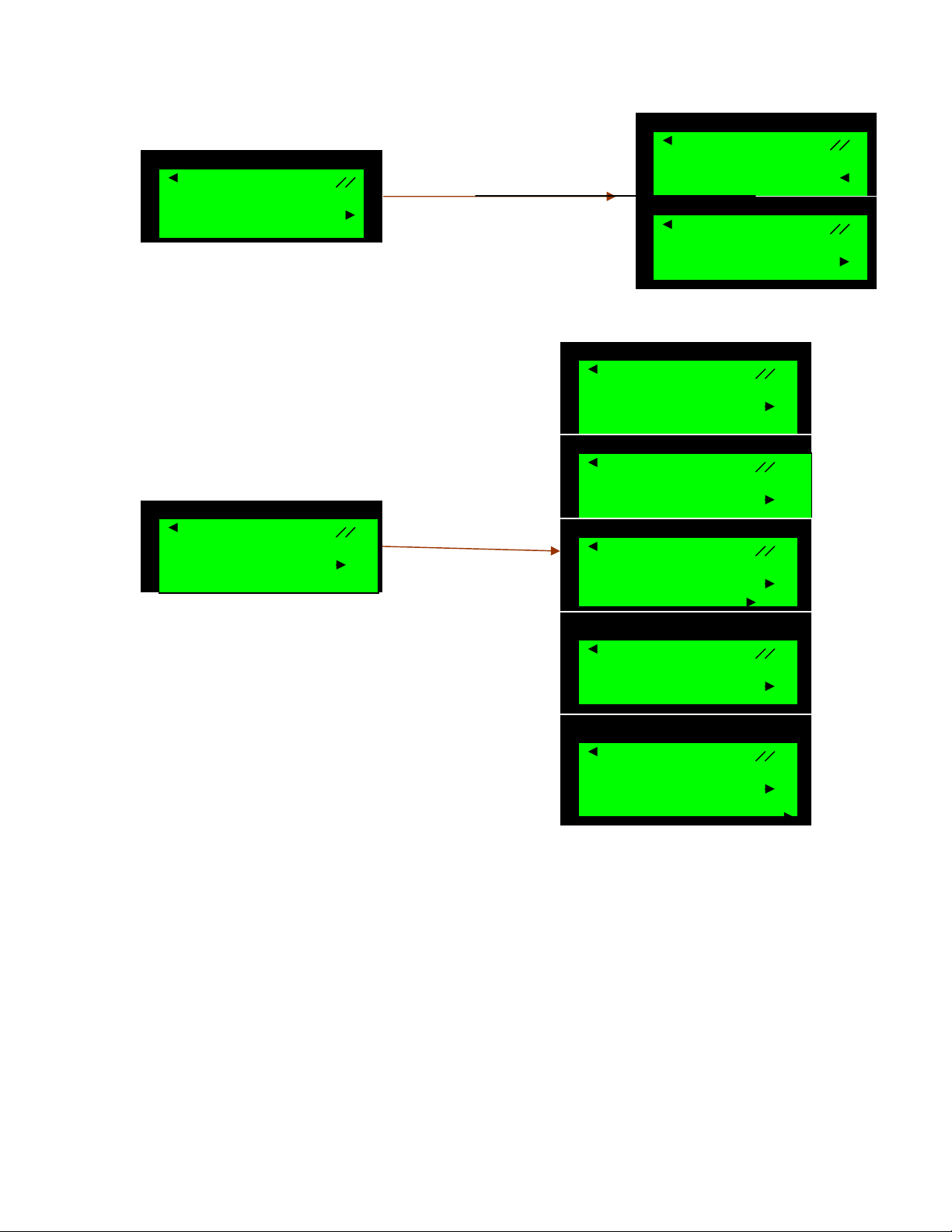
Connection type
NomVolt L
-L
*416 Volts
NomVolt L
-L
NomVolt L
-L
NomVolt L
-L
600 Volts
Freq
*50 Hz
Freq
Main Menu
Alt SetUp
Main Menu
Main Menu
Main Menu
Main Menu
Main Menu
Freq
Phase Type
Phase Type
Phase Type
CT Ratio
CT Ratio
Connection type
Units
Main Menu
Units
Phase Type
CT Ratio
Connect type
*3 Phase
Single2 wire
Single 3 wire
*Star Connect
*100:5
200:5
60 Hz
Setup screen
NomVolt L-L
Delta Connect
440 Volts
480 Volts
Units
*USA
Metric
- 17 -
Oil Pr Input
Sensor config
Main Menu
Oil Pr Input
*Sensor
Main Menu
Customer I/O
Customer I/O
Customer
I/O
Customer O/P1
Customer O/P1
Customer O/P1
Customer O/P2
Customer O/p2
Customer O/P2
Cust I/P Flt1
Cust
I/P Flt1
Sensor Config
Setup screen
Customer I/O
Oil Pr Input
Switch
*Warning faults
Shutdown faults
Customer O/p1
Glow Plug
Customer O/P2
*Warning Faults
Cust I/P Flt 1
Shutdown Faults
*Warning Faults
Shutdown Faults
- 18 -
Genset Running
Battle Shot
Battle Shot
Main menu
Battle Shot
Main Menu
Hours Flt 1
Hours Flt 2
Hours Flt 3
Hours Flt 4
Hours Flt 5
Flt History
*Inactive
Active
0000.00 212
0002.10 002
0002.09 215
0002.00 074
0001.88 213
- 19 -
Ok
Reset
No Navigation is needed
To enter into CALIBRATION MODE-
Press
For 5 Sec
Entering into the
Config Mode…
SW PART 3267727
SW VER 1.01
Meter calibration screens
Keys Action
will increase the voltage value
will decrease the voltage value
will calibrate next value
will calibrate previous value
- 20 -
 Loading...