

CUMMINS Power Generation DQFAA, Power Generation DQFAC, Power Generation DQFAB, Power Generation DQFAD Installation Manual

InstallationInstallation ManualManual
Generator Set
QST30-G5 Engine with PowerCommand®3.3 Control
DQFAA (Spec G-K)
DQFAB (Spec G-K)
DQFAC (Spec G-K)
DQFAD (Spec G-K)
English
Original Instructions 6-2019 A053U867 (Issue 5)


Table of Contents
1. IMPORTANT SAFETY INSTRUCTIONS ....................................................................................... 1
1.1 Warning, Caution, and Note Styles Used in This Manual ..................................................... 1
1.2 General Information ................................................................................................................ 1
1.2.1 General Safety Precautions ......................................................................................... 2
1.3 Generator Set Safety Code .................................................................................................... 5
1.3.1 Generator Set Operating Areas ................................................................................... 5
1.3.2 Moving Parts Can Cause Severe Personal Injury or Death ........................................ 5
1.3.3 Positioning of Generator Set....................................................................................... 6
1.4 Electrical Shocks and Arc Flashes Can Cause Severe Personal Injury or Death.................. 6
1.4.1 Locking the Generator Set Out of Service ................................................................... 7
1.4.2 AC Supply and Isolation............................................................................................... 8
1.4.3 AC Disconnect Sources ............................................................................................... 8
1.5 Fuel and Fumes Are Flammable ............................................................................................ 8
1.5.1 Spillage ....................................................................................................................... 9
1.5.2 Fluid Containment....................................................................................................... 9
1.5.3 Do Not Operate in Flammable and Explosive Environments ...................................... 9
1.6 Exhaust Gases Are Deadly..................................................................................................... 9
1.6.1 Exhaust Precautions ................................................................................................... 9
1.7 Earth Ground Connection ..................................................................................................... 10
1.8 Decommissioning and Disassembly ..................................................................................... 11
2. INTRODUCTION.......................................................................................................................... 13
2.1 About This Manual................................................................................................................ 13
2.1.1 Additional Installation Manual Information ................................................................. 13
2.2 Schedule of Abbreviations .................................................................................................... 14
2.3 Related Literature ................................................................................................................. 15
2.3.1 Further Information - Literature .................................................................................. 16
2.4 After Sales Services.............................................................................................................. 16
2.4.1 Maintenance.............................................................................................................. 16
2.4.2 Warranty..................................................................................................................... 16
3. SYSTEM OVERVIEW .................................................................................................................. 19
3.1 Generator Set Identification .................................................................................................. 19
3.1.1 Nameplate.................................................................................................................. 19
3.1.2 Generator Set Components ....................................................................................... 19
3.2 Generator Set Rating ............................................................................................................ 20
3.3 Derating Factors ................................................................................................................... 20
3.4 Engine Components ............................................................................................................. 21
3.5 System Options..................................................................................................................... 22
3.5.1 Introduction ................................................................................................................ 22
3.5.2 Battery Charger.......................................................................................................... 22
3.5.3 Day Tank.................................................................................................................... 23
iA053U867 (Issue 5) Copyright © 2019 Cummins Inc.

Table of Contents 6-2019
3.5.4 Enclosures ................................................................................................................. 23
3.5.5 Fuel Transfer Pump ................................................................................................... 24
3.5.6 Heaters....................................................................................................................... 25
3.5.7 Remote Radiator Installation ..................................................................................... 26
3.5.8 Relays ........................................................................................................................ 26
3.5.9 Seismic Installation Requirements............................................................................. 26
3.5.10 Sensors.................................................................................................................... 26
4. INSTALLATION OVERVIEW ....................................................................................................... 29
4.1 Application and Installation ................................................................................................... 29
4.2 Safety Considerations........................................................................................................... 29
4.3 Standby Heating Devices...................................................................................................... 29
4.4 Product Modifications............................................................................................................ 30
4.5 De-Rating Factors................................................................................................................ 30
5. SPECIFICATIONS ....................................................................................................................... 31
5.1 Generator Set Specifications ................................................................................................ 31
5.2 Engine Fuel Consumption..................................................................................................... 32
6. INSTALLING THE GENERATOR SET ........................................................................................ 33
6.1 Transportation ....................................................................................................................... 33
6.2 Location ................................................................................................................................ 34
6.3 Moving the Generator Set..................................................................................................... 35
6.3.1 Rigging Instructions.................................................................................................... 36
6.4 Mounting ............................................................................................................................... 37
6.5 Access to Generator Set....................................................................................................... 38
6.6 Seismic Installation Notes..................................................................................................... 38
7. MECHANICAL CONNECTIONS .................................................................................................. 41
7.1 Fuel System .......................................................................................................................... 41
7.1.1 Fuel Return Restrictions (or Pressure) Limit.............................................................. 42
7.1.2 Fuel Line Connections ............................................................................................... 42
7.1.3 Engine Fuel Connections........................................................................................... 43
7.1.4 Supply Tank ............................................................................................................... 44
7.1.5 Fuel Inlet Pressure/Restriction Limit .......................................................................... 45
7.1.6 Day Tank.................................................................................................................... 45
7.1.7 Fuel Transfer Pump ................................................................................................... 46
7.1.8 Fuel Additives............................................................................................................. 46
7.2 Exhaust System .................................................................................................................... 47
7.3 Ventilation and Cooling......................................................................................................... 51
7.4 Vents and Ducts.................................................................................................................... 51
7.5 Dampers ............................................................................................................................... 52
7.6 Air Inlet and Outlet Openings................................................................................................ 52
7.7 Remote Radiator Cooling .................................................................................................... 54
7.7.1 Remote Radiator Installation...................................................................................... 54
7.8 Breakerless Conductor Connections .................................................................................... 55
7.8.1 Overload and Short Circuit Protection of Generator .................................................. 55
ii A053U867 (Issue 5)Copyright © 2019 Cummins Inc.

Table of Contents6-2019
7.8.2 AmpSentry Protective Relay Time-Over Current Characteristic Curve ..................... 57
7.8.3 Coordination of Protective Devices............................................................................ 59
7.8.4 Additional AmpSentry Protective Relay Information .................................................. 59
8. DC CONTROL WIRING ............................................................................................................... 61
8.1 Guidelines for Customer Connections to the Control System .............................................. 61
8.1.1 Digital Connections .................................................................................................... 62
8.1.2 Relay Connections..................................................................................................... 62
8.2 PowerCommand 3.3 Customer Connections ....................................................................... 62
8.2.1 Configurable Outputs ................................................................................................. 62
8.2.2 Remote Start.............................................................................................................. 62
8.2.3 Configurable Inputs.................................................................................................... 63
8.2.4 Remote Emergency Stop........................................................................................... 63
8.3 Customer Relays .................................................................................................................. 63
8.3.1 Location of Customer Relays..................................................................................... 63
9. AC ELECTRICAL CONNECTIONS ............................................................................................. 65
9.1 AC Distribution Panel Connections....................................................................................... 66
9.1.1 AC Distribution Panel................................................................................................. 67
9.2 Transfer Switch ..................................................................................................................... 68
9.3 Alternator Voltage Connections ............................................................................................ 69
9.4 Load Connections ................................................................................................................. 70
9.4.1 Generator Set Load Cable Installation....................................................................... 70
9.4.2 Cabling through Non-Ferrous Gland Plates............................................................... 70
9.4.3 Cabling through Ferrous Gland Plates ...................................................................... 70
9.4.4 Distribution Cables..................................................................................................... 70
9.5 Installation of s-CAN Network Cable .................................................................................... 71
9.6 Load Balancing ..................................................................................................................... 73
9.7 Fuel Transfer Pump Installation............................................................................................ 73
9.7.1 Fuel Transfer Pump Control AC Connections ........................................................... 73
9.8 Current Transformers............................................................................................................ 75
9.9 Coolant Heater...................................................................................................................... 75
9.10 Alternator Heaters............................................................................................................... 75
9.10.1 Alternator Heater Connection .................................................................................. 75
9.11 Control Box Heater ............................................................................................................. 75
9.11.1 Control Box Heater Installation ................................................................................ 75
9.12 Battery Commissioning ....................................................................................................... 76
9.12.1 Safety Precautions................................................................................................... 77
9.12.2 Pre-Commissioning Procedure ................................................................................ 78
9.12.3 Filling the Battery with Electrolyte............................................................................ 78
9.12.4 Charging - Commissioning ...................................................................................... 78
9.12.5 Connecting the Battery to the Generator Set........................................................... 79
9.12.6 Electrolyte - Specific Gravity and Temperature ....................................................... 79
9.13 Battery Charger................................................................................................................... 81
9.13.1 PowerCommand Battery Charger - 15 Amp at 12 Volt and 12 Amp at 24 Volt....... 81
9.14 Grounding ........................................................................................................................... 82
iiiA053U867 (Issue 5) Copyright © 2019 Cummins Inc.

Table of Contents 6-2019
10. PRE-START PREPARATION..................................................................................................... 85
10.1 Initial Pre-start Checks........................................................................................................ 85
10.2 Electrical System ................................................................................................................ 86
10.3 Battery Connections............................................................................................................ 86
10.4 Site-Specific Configuration.................................................................................................. 87
10.5 Starting................................................................................................................................ 87
11. INSTALLATION CHECKLIST ..................................................................................................... 89
11.1 Checklist ............................................................................................................................. 89
12. MANUFACTURING FACILITIES ................................................................................................ 93
12.1 How to Obtain Service ....................................................................................................... 93
12.1.1 Locating a Distributor ............................................................................................... 93
APPENDIX A. ALTERNATOR RECONNECT DRAWING ................................................................ 95
A.1 Alternator Reconnect Drawing.............................................................................................. 97
A.2 Alternator Reconnect Drawing.............................................................................................. 99
APPENDIX B. CUSTOMER CONNECTIONS ................................................................................ 107
B.1 Control Wiring Diagrams (0630-3440)................................................................................ 109
APPENDIX C. OUTLINE DRAWINGS ............................................................................................ 121
C.1 Generator Set Outline Drawing (A053G789) - Set Mounted Radiator............................... 123
C.2 Generator Set Outline Drawing (A049K674) - Set Mounted Radiator ............................... 127
C.3 Generator Set Outline Drawing (A062H932) - Set Mounted Radiator ............................... 131
C.4 Generator Set Outline Drawing (A053G787) - Remote Radiator....................................... 135
C.5 Generator Set Outline Drawing (A062M281) - Remote Radiator....................................... 140
APPENDIX D. WIRING DIAGRAMS............................................................................................... 145
D.1 PCC3300 Wiring Diagram (A053C830) ............................................................................. 147
D.2 Outline Drawing and Schematic - Heater........................................................................... 154
D.3 Wiring of Optional Equipment ............................................................................................ 155
APPENDIX E. SEISMIC REQUIREMENTS.................................................................................... 157
E.1 Seismic Installation Instructions (A045K403) ..................................................................... 159
iv A053U867 (Issue 5)Copyright © 2019 Cummins Inc.
1 IMPORTANT SAFETY INSTRUCTIONS
SAVE THESE INSTRUCTIONS. This manual contains important instructions that should be followed
during installation and maintenance of the generator set and batteries.
Safe and efficient operation can be achieved only if the equipment is properly operated and maintained.
Many accidents are caused by failure to follow fundamental rules and precautions.
1.1 Warning, Caution, and Note Styles Used in This Manual
The following safety styles and symbols found throughout this manual indicate potentially hazardous
conditions to the operator, service personnel, or equipment.
DANGER
Indicates a hazardous situation that, if not avoided, will result in death or serious injury.
WARNING
Indicates a hazardous situation that, if not avoided, could result in death or serious injury.
CAUTION
Indicates a hazardous situation that, if not avoided, could result in minor or moderate injury.
Indicates information considered important, but not hazard-related (e.g., messages relating to
property damage).
1.2 General Information
This manual should form part of the documentation package supplied by Cummins with specific generator
sets. In the event that this manual has been supplied in isolation, please contact your authorized
distributor.
It is in the operator’s interest to read and understand all warnings and cautions contained within
the documentation relevant to the generator set, its operation and daily maintenance.
NOTICE
NOTICE
1A053U867 (Issue 5) Copyright © 2019 Cummins Inc.

1. IMPORTANT SAFETY INSTRUCTIONS 6-2019
1.2.1 General Safety Precautions
WARNING
Hot Pressurized Liquid
Contact with hot liquid can cause severe burns.
Do not open the pressure cap while the engine is running. Let the engine cool down before
removing the cap. Turn the cap slowly and do not open it fully until the pressure has been
relieved.
WARNING
Moving Parts
Moving parts can cause severe personal injury.
Use extreme caution around moving parts. All guards must be properly fastened to prevent
unintended contact.
WARNING
Toxic Hazard
Used engine oils have been identified by some state and federal agencies to cause cancer or
reproductive toxicity.
Do not ingest, breathe the fumes, or contact used oil when checking or changing engine oil.
Wear protective gloves and face guard.
WARNING
Electrical Generating Equipment
Incorrect operation can cause severe personal injury or death.
Do not operate equipment when fatigued, or after consuming any alcohol or drug.
WARNING
Toxic Gases
Substances in exhaust gases have been identified by some state and federal agencies to cause
cancer or reproductive toxicity.
Do not breathe in or come into contact with exhaust gases.
WARNING
Combustible Liquid
Ignition of combustible liquids is a fire or explosion hazard which can cause severe burns or
death.
Do not store fuel, cleaners, oil, etc., near the generator set.
WARNING
High Noise Level
Generator sets in operation emit noise, which can cause hearing damage.
Wear appropriate ear protection at all times.
2 A053U867 (Issue 5)Copyright © 2019 Cummins Inc.
1. IMPORTANT SAFETY INSTRUCTIONS6-2019
WARNING
Hot Surfaces
Contact with hot surfaces can cause severe burns.
The unit is to be installed so that the risk of hot surface contact by people is minimized. Wear
appropriate PPE when working on hot equipment and avoid contact with hot surfaces.
WARNING
Electrical Generating Equipment
Incorrect operation and maintenance can result in severe personal injury or death.
Make sure that only suitably trained and experienced service personnel perform electrical and/or
mechanical service.
WARNING
Toxic Hazard
Ethylene glycol, used as an engine coolant, is toxic to humans and animals.
Wear appropriate PPE. Clean up coolant spills and dispose of used coolant in accordance with
local environmental regulations.
WARNING
Combustible Liquid
Ignition of combustible liquids is a fire or explosion hazard which can cause severe burns or
death.
Do not use combustible liquids like ether.
WARNING
Automated Machinery
Accidental or remote starting of the generator set can cause severe personal injury or death.
Isolate all auxiliary supplies and use an insulated wrench to disconnect the starting battery
cables (negative [–] first).
WARNING
Fire Hazard
Materials drawn into the generator set are a fire hazard. Fire can cause severe burns or death.
Make sure the generator set is mounted in a manner to prevent combustible materials from
accumulating under the unit.
WARNING
Fire Hazard
Accumulated grease and oil are a fire hazard. Fire can cause severe burns or death.
Keep the generator set and the surrounding area clean and free from obstructions. Repair oil
leaks promptly.
3A053U867 (Issue 5) Copyright © 2019 Cummins Inc.
1. IMPORTANT SAFETY INSTRUCTIONS 6-2019
WARNING
Fall Hazard
Falls can result in severe personal injury or death.
Make sure that suitable equipment for performing tasks at height are used in accordance with
local guidelines and legislation.
WARNING
Fire Hazard
Materials drawn into the generator set are a fire hazard. Fire can cause severe burns or death.
Keep the generator set and the surrounding area clean and free from obstructions.
WARNING
Pressurized System
Pressurized systems can rupture/leak which can result in severe personal injury or death.
Use appropriate lock out/tag out safety procedures to isolate from all energy sources before
performing any service tasks. Use PPE.
WARNING
Confined Areas
Confined spaces or areas with restricted access or potential to entrap can cause severe personal
injury or death.
Use appropriate lock out/tag out safety procedures to isolate from all energy sources. Use PPE.
Follow site specific lone worker protocols/permits to work.
CAUTION
Manual Handling Heavy Objects
Handling heavy objects can cause severe personal injury.
Use appropriate lifting equipment and perform tasks with two people where doing so would make
completion of the task safe.
CAUTION
Power Tools and Hand Tools
Tools can cause cuts, abrasions, bruising, puncture injuries.
Only trained and experienced personnel should use power tools and hand tools. Use PPE.
CAUTION
Sharp Edges and Sharp Points
Projecting corners/parts may cause cuts, abrasions and other personal injury.
Use PPE. Be aware of sharp edges and corners/sharp points. Cover/protect them.
NOTICE
Keep multi-type ABC fire extinguishers close by. Class A fires involve ordinary combustible
materials such as wood and cloth. Class B fires involve combustible and flammable liquid fuels
and gaseous fuels. Class C fires involve live electrical equipment. (Refer to NFPA No. 10 in the
applicable region.)
4 A053U867 (Issue 5)Copyright © 2019 Cummins Inc.

NOTICE
Before performing maintenance and service procedures on enclosed generator sets, make sure
the service access doors are secured open.
NOTICE
Stepping on the generator set can cause parts to bend or break, leading to electrical shorts, or to
fuel leaks, coolant leaks, or exhaust leaks. Do not step on the generator set when entering or
leaving the generator set room.
NOTICE
Remove fuel from subbase fuel tank before conducting any hot work.
1.3 Generator Set Safety Code
Before operating the generator set, read the manuals and become familiar with them and the equipment.
Safe and efficient operation can be achieved only if the equipment is properly operated and maintained.
Many accidents are caused by failure to follow fundamental rules and precautions.
1. IMPORTANT SAFETY INSTRUCTIONS6-2019
WARNING
Electrical Generating Equipment
Incorrect operation and maintenance can result in severe personal injury or death.
Read and follow all Safety Precautions, Warnings, and Cautions throughout this manual and the
documentation supplied with the generator set.
1.3.1 Generator Set Operating Areas
WARNING
Ejected Debris
Debris ejected during destructive failure can cause serious injury or death by impact, severing or
stabbing.
Do not to stand alongside the engine or alternator while the generator set is running.
• Operators must not stand alongside the engine or alternator while the generator set is running,
unless the risks of doing so have been assessed and adequate mitigation steps have been taken.
• If there are operation/maintenance procedures that require spending time alongside the generator
set when it is running, take every precaution to perform these tasks safely. Keep time spent
performing these tasks to a minimum.
• Be aware of the product environment. Other equipment may be in operation or energized in the
surrounding area.
1.3.2 Moving Parts Can Cause Severe Personal Injury or Death
• Keep hands, clothing, and jewelry away from moving parts.
5A053U867 (Issue 5) Copyright © 2019 Cummins Inc.
1. IMPORTANT SAFETY INSTRUCTIONS 6-2019
• Before starting work on the generator set, disconnect the battery charger from its AC source, then
disconnect the starting batteries using an insulated wrench, negative (–) cable first. This will prevent
accidental starting.
• Make sure that fasteners on the generator set are secure. Tighten supports and clamps; keep
guards in position over fans, drive belts, etc.
• Do not wear loose clothing or jewelry in the vicinity of moving parts or while working on electrical
equipment. Loose clothing and jewelry can become caught in moving parts.
• If any adjustments must be made while the unit is running, use extreme caution around hot
manifolds, moving parts, etc.
1.3.3 Positioning of Generator Set
The generator set should be placed on level ground with adequate open space around it. The immediate
area around the generator set should be free of any flammable material.
NOTICE
Access or service doors must be closed and locked before repositioning, and they must remain
locked during transportation and siting.
NOTICE
The generator set is capable of operating at inclines of up to +/– 2.5 degrees.
1.4 Electrical Shocks and Arc Flashes Can Cause Severe Personal Injury or Death
WARNING
Electric Shock Hazard
Voltages and currents present an electrical shock hazard that can cause severe burns or death.
Contact with exposed energized circuits with potentials of 50 Volts AC or 75 Volts DC or higher
can cause electrical shock and electrical arc flash. Refer to standard NFPA 70E or equivalent
safety standards in corresponding regions for details of the dangers involved and for the safety
requirements.
Guidelines to follow when working on de-energized electrical systems:
• Use proper PPE. Do not wear jewelry and make sure that any conductive items are removed from
pockets as these items can fall into equipment and the resulting short circuit can cause shock or
burning. Refer to standard NFPA 70E for PPE standards.
• De-energize and lockout/tagout electrical systems prior to working on them. Lockout/Tagout is
intended to prevent injury due to unexpected start-up of equipment or the release of stored energy.
Please refer to Locking the Generator Set Out of Service section for more information.
• De-energize and lockout/tagout all circuits and devices before removing any protective shields or
making any measurements on electrical equipment.
• Follow all applicable regional electrical and safety codes.
Guidelines to follow when working on energized electrical systems:
6 A053U867 (Issue 5)Copyright © 2019 Cummins Inc.
1. IMPORTANT SAFETY INSTRUCTIONS6-2019
NOTICE
It is the policy of Cummins Inc. to perform all electrical work in a de-energized state. However,
employees or suppliers may be permitted to occasionally perform work on energized electrical
equipment only when qualified and authorized to do so and when troubleshooting, or if deenergizing the equipment would create a greater risk or make the task impossible and all other
alternatives have been exhausted.
NOTICE
Exposed energized electrical work is only allowed as per the relevant procedures and must be
undertaken by a Cummins authorized person with any appropriate energized work permit for the
work to be performed while using proper PPE, tools and equipment.
In summary:
• Do not tamper with or bypass interlocks unless you are authorized to do so.
• Understand and assess the risks - use proper PPE. Do not wear jewelry and make sure that any
conductive items are removed from pockets as these items can fall into equipment and the resulting
short circuit can cause shock or burning. Refer to standard NFPA 70E for PPE standards.
• Make sure that an accompanying person who can undertake a rescue is nearby.
1.4.1 Locking the Generator Set Out of Service
Before any work is carried out for maintenance, etc., the generator set must be immobilized. Even if the
generator set is put out of service by pressing the Off switch on the operator panel, the generator set
cannot be considered safe to work on until the engine is properly immobilized, as detailed in the following
procedures.
NOTICE
Refer also to the engine specific Operator Manual. This manual contains specific equipment
instructions that may differ from the standard generator set.
1.4.1.1 Immobilizing for Safe Working
To immobilize the generator set:
1. Press the Off mode switch on the operator panel to shut down the generator set.
2. Press the Emergency Stop button. This prevents the generator set starting, regardless of the Start
signal source and provides an additional safety step for immobilizing the generator set.
NOTICE
When the Emergency Stop button is pressed, the operator panel indicates a Shutdown
condition. The red Shutdown status LED illuminates and a message is displayed.
NOTICE
This condition is stored in the Fault History.
3. As an additional precaution, thoroughly ventilate the plant room before disconnecting any leads.
4. Isolate and lock off the supply to the heater, where fitted.
7A053U867 (Issue 5) Copyright © 2019 Cummins Inc.

1. IMPORTANT SAFETY INSTRUCTIONS 6-2019
5. Isolate and lock off the supply to the battery charger, where fitted.
6. Isolate the fuel supply to the engine.
7. Using an insulated wrench, disconnect the negative (–) cable first on the starting batteries and
control system batteries (if separate).
8. Fit warning notices at each of the above points to indicate Maintenance in Progress – Plant
Immobilized for Safe Working.
1.4.2 AC Supply and Isolation
NOTICE
Local electrical codes and regulations (for example, BS EN 12601:2010 Reciprocating internal
combustion engine driven generating sets) may require the installation of a disconnect means
for the generator set, either on the generator set or where the generator set conductors enter a
facility.
NOTICE
The AC supply must have the correct over current and earth fault protection according to local
electrical codes and regulations. This equipment must be earthed (grounded).
It is the sole responsibility of the customer to provide AC power conductors for connection to load devices
and the means to isolate the AC input to the terminal box; these must comply with local electrical codes
and regulations. Refer to the wiring diagram supplied with the generator set.
The disconnecting device is not provided as part of the generator set, and Cummins accepts no
responsibility for providing the means of isolation.
1.4.2.1 AmpSentry
Generator sets with PC 3.3 control utilize AmpSentry™ protective relay which includes integral AC
protective functions for the alternator and conductors, if conductors are rated for operation at a minimum
of 100% of the generator nameplate rating.
1.4.3 AC Disconnect Sources
WARNING
Hazardous Voltage
Contact with high voltages can cause severe electrical shock, burns, or death.
The equipment may have more than one source of electrical energy. Disconnecting one source
without disconnecting the others presents a shock hazard. Before starting work, disconnect the
equipment, and verify that all sources of electrical energy have been removed.
1.5 Fuel and Fumes Are Flammable
Fire, explosion, and personal injury or death can result from improper practices.
• Do not fill fuel tanks while the engine is running unless the tanks are outside the engine
compartment. Fuel contact with hot engine or exhaust is a potential fire hazard.
• Do not permit any flame, cigarette, pilot light, spark, arcing equipment, or other ignition source near
the generator set or fuel tank.
8 A053U867 (Issue 5)Copyright © 2019 Cummins Inc.

• Fuel lines must be adequately secured and free of leaks. Fuel connection at the engine should be
made with an approved flexible line. Do not use copper piping on flexible lines as copper will
become brittle if continuously vibrated or repeatedly bent.
• Make sure all fuel supplies have a positive shutoff valve.
• Make sure the battery area has been well-ventilated prior to servicing near it. Lead-acid batteries
emit a highly explosive hydrogen gas that can be ignited by arcing, sparking, smoking, etc.
1.5.1 Spillage
Any spillage that occurs during fueling, oil top-off, or oil change must be cleaned up before starting the
generator set.
1.5.2 Fluid Containment
Where spillage containment is not part of a Cummins supply, it is the responsibility of the
installer to provide the necessary containment to prevent contamination of the environment,
especially water courses and sources.
If fluid containment is incorporated into the bedframe, it must be inspected at regular intervals. Any liquid
present should be drained out and disposed of in line with local health and safety regulations. Failure to
perform this action may result in spillage of liquids which could contaminate the surrounding area.
1. IMPORTANT SAFETY INSTRUCTIONS6-2019
NOTICE
Any other fluid containment area must also be checked and emptied, as described above.
1.5.3 Do Not Operate in Flammable and Explosive Environments
Flammable vapor can cause an engine to over speed and become difficult to stop, resulting in possible
fire, explosion, severe personal injury, and death. Do not operate a generator set where a flammable
vapor environment can be created, unless the generator set is equipped with an automatic safety device
to block the air intake and stop the engine. The owners and operators of the generator set are solely
responsible for operating the generator set safely. Contact your authorized Cummins distributor for more
information.
1.6 Exhaust Gases Are Deadly
• Provide an adequate exhaust system to properly expel discharged gases away from enclosed or
sheltered areas, and areas where individuals are likely to congregate. Visually and audibly inspect
the exhaust system daily for leaks per the maintenance schedule. Make sure that exhaust manifolds
are secured and not warped. Do not use exhaust gases to heat a compartment.
• Make sure the unit is well ventilated.
1.6.1 Exhaust Precautions
WARNING
Hot Exhaust Gases
Contact with hot exhaust gases can cause severe burns.
Wear personal protective equipment when working on equipment.
9A053U867 (Issue 5) Copyright © 2019 Cummins Inc.
1. IMPORTANT SAFETY INSTRUCTIONS 6-2019
WARNING
Hot Surfaces
Contact with hot surfaces can cause severe burns.
The unit is to be installed so that the risk of hot surface contact by people is minimized. Wear
appropriate PPE when working on hot equipment and avoid contact with hot surfaces.
WARNING
Toxic Gases
Inhalation of exhaust gases can cause asphyxiation and death.
Pipe exhaust gas outside and away from windows, doors, or other inlets to buildings. Do not
allow exhaust gas to accumulate in habitable areas.
WARNING
Fire Hazard
Contaminated insulation is a fire hazard. Fire can cause severe burns or death.
Remove any contaminated insulation and dispose of it in accordance with local regulations.
The exhaust outlet may be sited at the top or bottom of the generator set. Make sure that the exhaust
outlet is not obstructed. Personnel using this equipment must be made aware of the exhaust position.
Position the exhaust away from flammable materials - in the case of exhaust outlets at the bottom, make
sure that vegetation is removed from the vicinity of the exhaust.
The exhaust pipes may have some insulating covers fitted. If these covers become contaminated they
must be replaced before the generator set is run.
To minimize the risk of fire, make sure the following steps are observed:
• Make sure that the engine is allowed to cool thoroughly before performing maintenance or operation
tasks.
• Clean the exhaust pipe thoroughly.
1.7 Earth Ground Connection
The neutral of the generator set may be required to be bonded to earth ground at the generator set
location, or at a remote location, depending on system design requirements. Consult the engineering
drawings for the facility or a qualified electrical design engineer for proper installation.
NOTICE
The end user is responsible to make sure that the ground connection point surface area is clean
and free of rust before making a connection.
NOTICE
The end user is responsible for making sure that an earthing arrangement that is compliant with
local conditions is established and tested before the equipment is used.
10 A053U867 (Issue 5)Copyright © 2019 Cummins Inc.

1. IMPORTANT SAFETY INSTRUCTIONS6-2019
1.8 Decommissioning and Disassembly
NOTICE
Decommissioning and disassembly of the generator set at the end of its working life must
comply with local guidelines and legislation for disposal/recycling of components and
contaminated fluids. This procedure must only be carried out by suitably trained and
experienced service personnel. For more information contact your authorized distributor.
11A053U867 (Issue 5) Copyright © 2019 Cummins Inc.

1. IMPORTANT SAFETY INSTRUCTIONS 6-2019
This page is intentionally blank.
12 A053U867 (Issue 5)Copyright © 2019 Cummins Inc.

2 Introduction
Hazardous Voltage
Contact with high voltages can cause severe electrical shock, burns, or death.
Make sure that only a trained and experienced electrician makes generator set electrical output
connections, in accordance with the installation instructions and all applicable codes.
Electrical Generating Equipment
Faulty electrical generating equipment can cause severe personal injury or death.
Generator sets must be installed, certified, and operated by trained and experienced persons in
accordance with the installation instructions and all applicable codes.
2.1 About This Manual
The purpose of this manual is to provide the users with sound, general information. It is for guidance and
assistance with recommendations for correct and safe procedures. Cummins Inc. cannot accept any
liability whatsoever for problems arising as a result of following recommendations in this manual.
The information contained within the manual is based on information available at the time of going to print.
In line with Cummins Inc. policy of continuous development and improvement, information may change at
any time without notice. The users should therefore make sure that before commencing any work, they
have the latest information available. The latest version of this manual is available on QuickServe Online
(https://quickserve.cummins.com).
WARNING
WARNING
Users are respectfully advised that, in the interests of good practice and safety, it is their responsibility to
employ competent persons to carry out any installation work. Consult your authorized distributor for further
installation information. It is essential that the utmost care is taken with the application, installation, and
operation of any engine due to their potentially hazardous nature. Careful reference should also be made
to other Cummins Inc. literature. A generator set must be operated and maintained properly for safe and
reliable operation.
For further assistance, contact your authorized distributor.
2.1.1 Additional Installation Manual Information
The purpose of this manual is to provide the Installation Engineer with sound, general information for the
installation of the generator set. Refer to the Generator Set Operator Manual for additional information
which must also be read before operating the set.
This manual provides installation instructions for the generator set models listed on the front cover. This
includes the following information:
• Mounting Recommendations - for fastening the generator set to a base and space requirements
for normal operation and service.
• Mechanical and Electrical Connections - covers most aspects of the generator set installation.
• Prestart - checklist of items or procedures needed to prepare the generator set for operation.
• Installation Checklist - reference checks upon completion of the installation.
13A053U867 (Issue 5) Copyright © 2019 Cummins Inc.

2. Introduction 6-2019
This manual DOES NOT provide application information for selecting a generator set or designing the
complete installation. If it is necessary to design the various integrated systems (fuel, exhaust, cooling,
etc.), additional information is required. Review standard installation practices. For engineering data
specific to the generator set, refer to the Specification and Data Sheets. For application information, refer
to Application Manual T-030, "Liquid Cooled Generator Sets." To find this manual online:
1. Go to powersuite.cummins.com
2. Click on "Login" on the Home page.
3. Click on "Library".
4. Click on "Technical Documents".
5. Click on "Technical information".
6. Click on "Liquid Cooled Genset Application Manual".
2.2 Schedule of Abbreviations
This list is not exhaustive. For example, it does not identify units of measure or acronyms that appear only
in parameters, event/fault names, or part/accessory names.
ABBR. DESCRIPTION ABBR. DESCRIPTION
AC Alternating Current LED Light-emitting Diode
AMP AMP, Inc., part of Tyco Electronics LTS Long Term Storage
ANSI American National Standards
Institute
ASOV Automatic Shut Off Valve MFM Multifunction Monitor
ASTM American Society for Testing and
Materials (ASTM International)
ATS Automatic Transfer Switch MLD Masterless Load Demand
AVR Automatic Voltage Regulator NC Normally Closed
AWG American Wire Gauge NC Not Connected
CAN Controlled Area Network NFPA National Fire Protection Agency
CB Circuit Breaker NO Normally Open
CE Conformité Européenne NWF Network Failure
CFM Cubic Feet per Minute OEM Original Equipment Manufacturer
CGT Cummins Generator Technologies OOR Out of Range
CMM Cubic Meters per Minute OORH / ORH Out of Range High
CT Current Transformer OORL / ORL Out of Range Low
LVRT Low Voltage Ride Through
Mil Std Military Standard
D-AVR Digital Automatic Voltage
Regulator
DC Direct Current PCC PowerCommand®Control
DEF Diesel Exhaust Fluid PGI Power Generation Interface
DPF Diesel Particulate Filter PGN Parameter Group Number
PB Push Button
14 A053U867 (Issue 5)Copyright © 2019 Cummins Inc.
2. Introduction6-2019
ABBR. DESCRIPTION ABBR. DESCRIPTION
ECM Engine Control Module PI Proportional/Integral
ECS Engine Control System PID Proportional / Integral / Derivative
EMI Electromagnetic interference PLC Programmable Logic Controller
EN European Standard PMG Permanent Magnet Generator
EPS Engine Protection System PPE Personal Protective Equipment
E-Stop Emergency Stop PT Potential Transformer
FAE Full Authority Electronic PTC Power Transfer Control
FMI Failure Mode Identifier PWM Pulse-width Modulation
FRT Fault Ride Through RFI Radio Frequency Interference
FSO Fuel Shutoff RH Relative Humidity
Genset Generator Set RMS Root Mean Square
GCP Generator Control Panel RTU Remote Terminal Unit
GND Ground SAE Society of Automotive Engineers
LCT Low Coolant Temperature SCR Selective Catalytic Reduction
HMI Human-machine Interface SPN Suspect Parameter Number
IC Integrated Circuit SWL Safe Working Load
ISO International Organization for
Standardization
LBNG Lean-burn Natural Gas UL Underwriters Laboratories
LCD Liquid Crystal Display UPS Uninterruptible Power Supply
2.3 Related Literature
Before any attempt is made to operate the generator set, the operator should take time to read all of the
manuals supplied with the generator set, and to familiarize themselves with the warnings and operating
procedures.
A generator set must be operated and maintained properly if you are to expect safe and reliable
operation. The Operator manual includes a maintenance schedule and a troubleshooting guide.
SW_B+ Switched B+
VPS Valve Proving System
CAUTION
The relevant manuals appropriate to your generator set are also available:
• Operator Manual for DQFAA, DQFAB, DQFAC, and DQFAD Generator Sets with PowerCommand
3.3 Controller (A053U864)
• Installation Manual for DQFAA, DQFAB, DQFAC, and DQFAD Generator Sets with
PowerCommand®3.3 Controller (A053U867)
• Service Manual for DQFAA, DQFAB, DQFAC, and DQFAD Generator Sets with PowerCommand
3.3 Controller (A053U869)
15A053U867 (Issue 5) Copyright © 2019 Cummins Inc.
®
®

2. Introduction 6-2019
• Parts Manual for DQFAA, DQFAB, DQFAC, and DQFAD Generator Sets with PowerCommand®3.3
Controller (961-0211)
• Service Manual for PowerCommand®3.3 Controller (960-0670)
• Alternator Service Manual for HC Alternator (A040J849)
• Alternator Service Manual for P7 Alternator (A040J850)
• Common Manual for Preventative Maintenance Requirements for High Range Standby Diesel
Generator Sets (A035G976)
• Engine Operator and Maintenance Manual for QST30-G5 Engine (3666134)
• Specification and Data Sheets
• Application Manual T-030: Liquid Cooled Generator Sets (A040S369)
• Parts Manual for HC Alternator (0900-9914)
• Parts Manual for P7 Alternator (0900-9912)
• Standard Repair Times - CJ Family (A029C347)
• Fuels for Cummins Engines Service Bulletin (3379001)
• Emissions Warranty Statement (A043G561)
• Warranty Manual (A040W374)
• Global Commercial Warranty Statement (A028U870)
2.3.1 Further Information - Literature
Contact your authorized distributor for more information regarding related literature for this product.
2.4 After Sales Services
Cummins offers a full range of maintenance and warranty services.
2.4.1 Maintenance
WARNING
Electrical Generating Equipment
Incorrect operation and maintenance can result in severe personal injury or death.
Make sure that only suitably trained and experienced service personnel perform electrical and/or
mechanical service.
For expert generator set service at regular intervals, contact your local distributor. Each local distributor
offers a complete maintenance contract package covering all items subject to routine maintenance,
including a detailed report on the condition of the generator set. In addition, this can be linked to a 24-hour
call-out arrangement, providing year-round assistance if necessary. Specialist engineers are available to
maintain optimum performance levels from generator sets. Maintenance tasks should only be undertaken
by trained and experienced technicians provided by your authorized distributor.
2.4.2 Warranty
For details of the warranty coverage for your generator set, refer to the Global Commercial Warranty
Statement listed in the Related Literature section.
16 A053U867 (Issue 5)Copyright © 2019 Cummins Inc.

In the event of a breakdown, prompt assistance can normally be given by factory trained service
technicians with facilities to undertake all minor and many major repairs to equipment on site.
Extended warranty coverage is also available.
For further warranty details, contact your authorized service provider.
Damage caused by failure to follow the manufacturer's recommendations will not be covered by
the warranty. Please contact your authorized service provider.
2.4.2.1 Warranty Limitations
For details of the warranty limitations for your generator set, refer to the warranty statement applicable to
the generator set.
2. Introduction6-2019
NOTICE
17A053U867 (Issue 5) Copyright © 2019 Cummins Inc.

2. Introduction 6-2019
This page is intentionally blank.
18 A053U867 (Issue 5)Copyright © 2019 Cummins Inc.
3 System Overview
This section provides an overview of the generator set.
3.1 Generator Set Identification
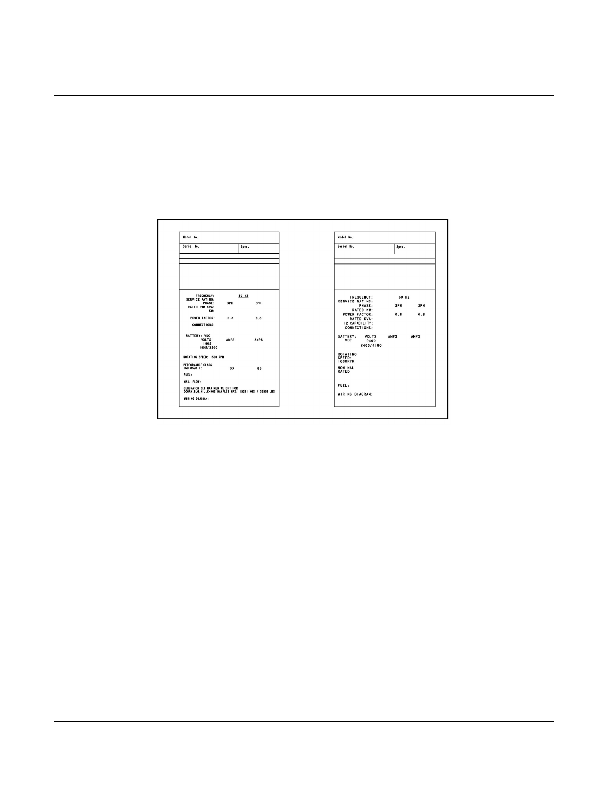
Each generator set is provided with a nameplate similar to that shown below. The nameplate provides
information unique to the generator set.
3.1.1 Nameplate
FIGURE 1. TYPICAL GENERATOR SET NAMEPLATE
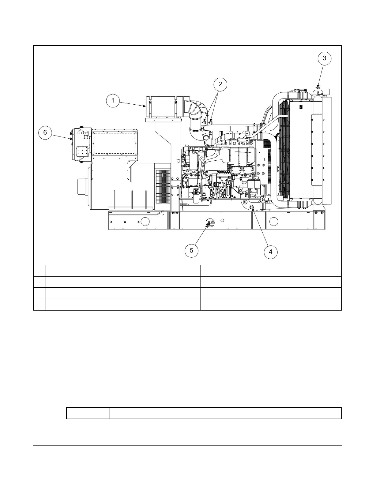
3.1.2 Generator Set Components
The main components of a QST30-G5 engine generator set are shown below, and referred to within this
section.
There are various options listed although they may not be available for all models.
19A053U867 (Issue 5) Copyright © 2019 Cummins Inc.
3. System Overview 6-2019
No Description No Description
1 Air Cleaners 4 Coolant Drain
2 Air Cleaner Service Indicators 5 Oil Drain
3 Radiator Cap 6 Control Panel
FIGURE 2. GENERATOR SET COMPONENTS
3.2 Generator Set Rating
For details of the generator set rating, refer to the generator set nameplate. For operation at temperatures
or altitudes above those stated on the nameplate, a derate may be necessary.
3.3 Derating Factors
TABLE 1. DQFAA DERATING FACTOR
Application Derating Factor
20 A053U867 (Issue 5)Copyright © 2019 Cummins Inc.

3. System Overview6-2019
Prime Engine power available up to 3150 m (10335 ft) at ambient temperatures up to 40 °C
(104 °F) and 2630 m (8628 ft) at ambient temperatures up to 50 °C (122 °F). Above
these elevations, derate at 3.5% per 305 m (1000 ft) and 7% per 10 °C (18 °F).
Standby Engine power available up to 3200 m (10500 ft) at ambient temperatures up to 40 °C
(104 °F) and 2200 m (7217 ft) at ambient temperatures up to 50 °C (122 °F). Above
these elevations, derate at 3.5% per 305 m (1000 ft) and 7% per 10 °C (18 °F).
TABLE 2. DQFAB DERATING FACTOR
Application Derating Factor
Prime Engine power available up to 2660 m (8727 ft) at ambient temperatures up to 40 °C
(104 °F) and 2090 m (6856 ft) at ambient temperatures up to 50 °C (122 °F). Above
these elevations, derate at 3.5% per 305 m (1000 ft) and 7% per 10 °C (18 °F)
Standby Engine power available up to 2700 m (8858 ft) at ambient temperatures up to 40 °C
(104 °F) and 1655 m (5429 ft) at ambient temperatures up to 50 °C (122 °F). Above
these elevations, derate at 3.5% per 305 m (1000 ft) and 7% per 10 °C (18 °F)
TABLE 3. DQFAC DERATING FACTOR
Application Derating Factor
Prime Engine power available up to 1650 m (5413 ft) at ambient temperatures up to 40 °C
(104 °F) and 975 m (3198 ft) at ambient temperatures up to 50 °C (122 °F). Above
these elevations, derate at 3.5% per 305 m (1000 ft) and 7% per 10 °C (18 °F).
Standby Engine power available up to 1720 m (5643 ft) at ambient temperatures up to 40 °C
(104 °F) and 595 m (1952 ft) at ambient temperatures up to 50 °C (122 °F). Above
these elevations, derate at 3.5% per 305 m (1000 ft) and 7% per 10 °C (18 °F)
TABLE 4. DQFAD DERATING FACTOR
Application Derating Factor
Prime Engine power available up to 727 m (2385 ft) at ambient temperatures up to 40 °C (104
°F). Above these elevations, derate at 3.5% per 305 m (1000 ft) and 7% per 10 °C (18
°F).
Standby Engine power available up to 701 m (2300 ft) at ambient temperatures up to 40 °C (104
°F). Above these elevations, derate at 3.5% per 305 m (1000 ft) and 7% per 10 °C (18
°F).
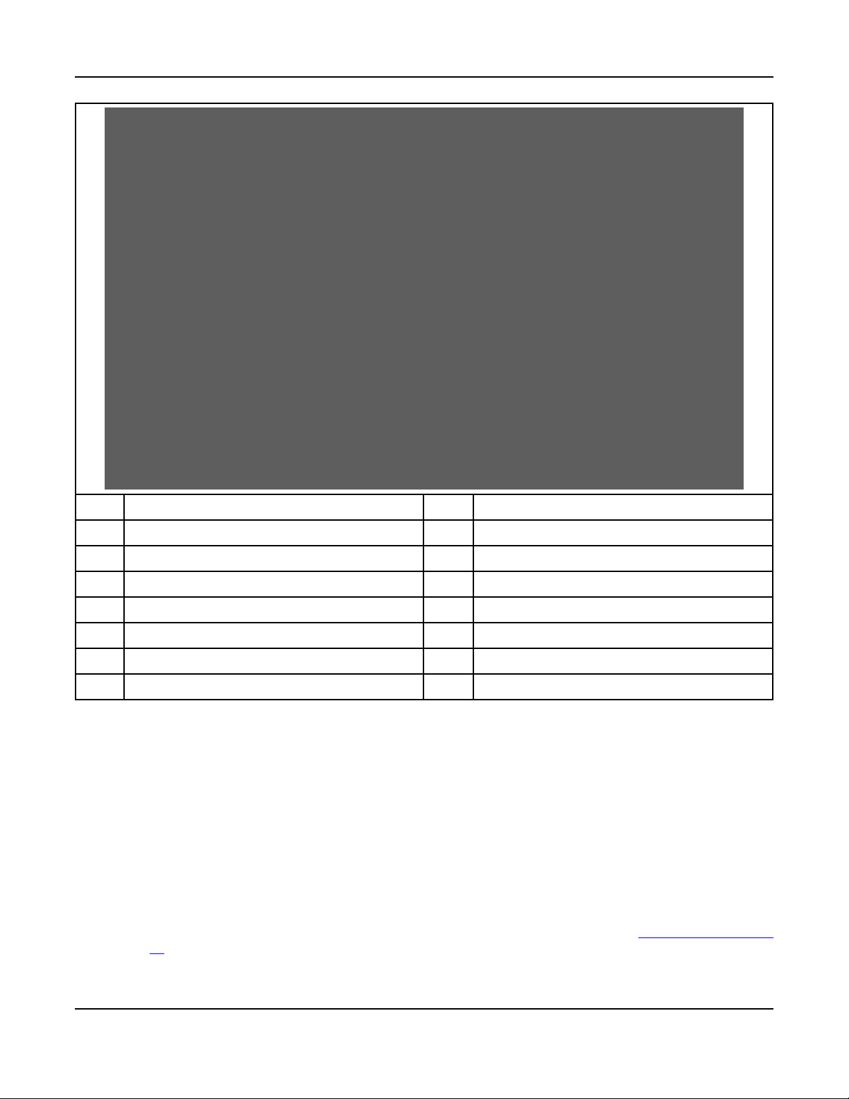
3.4 Engine Components
For additional engine specific information, refer to the relevant engine manual for the generator set.
21A053U867 (Issue 5) Copyright © 2019 Cummins Inc.
3. System Overview 6-2019
No. Description No. Description
1 Crankcase Breather Tube (each side) 8 Fuel system
2 Thermostat Housing 9 Fuel Outlet
3 Temperature Sender 10 Oil Pan
4 Water Outlet Connection 11 Oil Drain
5 Exhaust Outlet 12 Oil Fill
6 Magnetic Switch 13 Oil Check
7 Starting Motor 14 Water Inlet Connection
FIGURE 3. ENGINE COMPONENTS
3.5 System Options
3.5.1 Introduction
This section provides information for system options that require installation or customer connections
before commissioning the generator set. For more information regarding system options, refer to the
operator and service manual.
3.5.2 Battery Charger
Battery chargers can be wall, bench, or skid mounted. For more information, see Section 9.13 on page
81.
22 A053U867 (Issue 5)Copyright © 2019 Cummins Inc.

3.5.3 Day Tank
Some generator set installations include a fuel day tank. For more information, refer to Section 7.1.6 on
page 45.
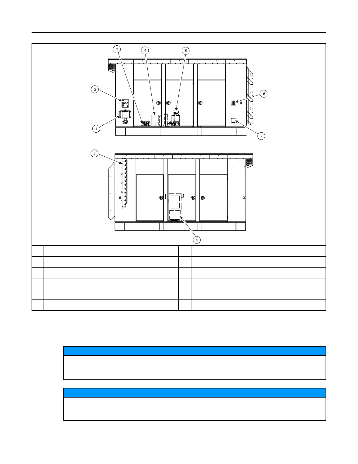
3.5.4 Enclosures
Enclosed generator sets can require optional features to be electrically connected during installation.
Use flexible conduit and stranded conductors for connections. Solid copper wire may break
during generator set operation.
3. System Overview6-2019
NOTICE
23A053U867 (Issue 5) Copyright © 2019 Cummins Inc.
3. System Overview 6-2019
No. Description No. Description
1 External Fuel Fill Box 6 Emergency Stop Switch
2 Fuel Alarm Panel 7 120 VAC External Receptacle
3 Overfill Alarm Assembly 8 Motorized Inlet Louver
4 Fuel Fill 9 AC Distribution Panel
5 Fuel System Control
FIGURE 4. TYPICAL OPTIONAL ENCLOSURE FEATURES
3.5.5 Fuel Transfer Pump
NOTICE
Damage to the fuel transfer pump can occur if the pump operates with no fuel in the supply tank.
Do not connect AC power to the fuel transfer pump control without having fuel in the supply
tank.
NOTICE
Power to the fuel transfer pump must be fed from a transfer switch and step-down transformer to
maintain 120V power to the pump when utility power in interrupted. Power must be supplied to
the transfer pump during the time the generator set is running or not running.
24 A053U867 (Issue 5)Copyright © 2019 Cummins Inc.
 Loading...