

CUMMINS Power Generation DQFAA, Power Generation DQFAC, Power Generation DQFAB, Power Generation DQFAD Installation Manual
Page 1

InstallationInstallation ManualManual
Generator Set
QST30-G5 Engine with PowerCommand®3.3 Control
DQFAA (Spec G-K)
DQFAB (Spec G-K)
DQFAC (Spec G-K)
DQFAD (Spec G-K)
English
Original Instructions 6-2019 A053U867 (Issue 5)
Page 2

Page 3

Table of Contents
1. IMPORTANT SAFETY INSTRUCTIONS ....................................................................................... 1
1.1 Warning, Caution, and Note Styles Used in This Manual ..................................................... 1
1.2 General Information ................................................................................................................ 1
1.2.1 General Safety Precautions ......................................................................................... 2
1.3 Generator Set Safety Code .................................................................................................... 5
1.3.1 Generator Set Operating Areas ................................................................................... 5
1.3.2 Moving Parts Can Cause Severe Personal Injury or Death ........................................ 5
1.3.3 Positioning of Generator Set....................................................................................... 6
1.4 Electrical Shocks and Arc Flashes Can Cause Severe Personal Injury or Death.................. 6
1.4.1 Locking the Generator Set Out of Service ................................................................... 7
1.4.2 AC Supply and Isolation............................................................................................... 8
1.4.3 AC Disconnect Sources ............................................................................................... 8
1.5 Fuel and Fumes Are Flammable ............................................................................................ 8
1.5.1 Spillage ....................................................................................................................... 9
1.5.2 Fluid Containment....................................................................................................... 9
1.5.3 Do Not Operate in Flammable and Explosive Environments ...................................... 9
1.6 Exhaust Gases Are Deadly..................................................................................................... 9
1.6.1 Exhaust Precautions ................................................................................................... 9
1.7 Earth Ground Connection ..................................................................................................... 10
1.8 Decommissioning and Disassembly ..................................................................................... 11
2. INTRODUCTION.......................................................................................................................... 13
2.1 About This Manual................................................................................................................ 13
2.1.1 Additional Installation Manual Information ................................................................. 13
2.2 Schedule of Abbreviations .................................................................................................... 14
2.3 Related Literature ................................................................................................................. 15
2.3.1 Further Information - Literature .................................................................................. 16
2.4 After Sales Services.............................................................................................................. 16
2.4.1 Maintenance.............................................................................................................. 16
2.4.2 Warranty..................................................................................................................... 16
3. SYSTEM OVERVIEW .................................................................................................................. 19
3.1 Generator Set Identification .................................................................................................. 19
3.1.1 Nameplate.................................................................................................................. 19
3.1.2 Generator Set Components ....................................................................................... 19
3.2 Generator Set Rating ............................................................................................................ 20
3.3 Derating Factors ................................................................................................................... 20
3.4 Engine Components ............................................................................................................. 21
3.5 System Options..................................................................................................................... 22
3.5.1 Introduction ................................................................................................................ 22
3.5.2 Battery Charger.......................................................................................................... 22
3.5.3 Day Tank.................................................................................................................... 23
iA053U867 (Issue 5) Copyright © 2019 Cummins Inc.
Page 4

Table of Contents 6-2019
3.5.4 Enclosures ................................................................................................................. 23
3.5.5 Fuel Transfer Pump ................................................................................................... 24
3.5.6 Heaters....................................................................................................................... 25
3.5.7 Remote Radiator Installation ..................................................................................... 26
3.5.8 Relays ........................................................................................................................ 26
3.5.9 Seismic Installation Requirements............................................................................. 26
3.5.10 Sensors.................................................................................................................... 26
4. INSTALLATION OVERVIEW ....................................................................................................... 29
4.1 Application and Installation ................................................................................................... 29
4.2 Safety Considerations........................................................................................................... 29
4.3 Standby Heating Devices...................................................................................................... 29
4.4 Product Modifications............................................................................................................ 30
4.5 De-Rating Factors................................................................................................................ 30
5. SPECIFICATIONS ....................................................................................................................... 31
5.1 Generator Set Specifications ................................................................................................ 31
5.2 Engine Fuel Consumption..................................................................................................... 32
6. INSTALLING THE GENERATOR SET ........................................................................................ 33
6.1 Transportation ....................................................................................................................... 33
6.2 Location ................................................................................................................................ 34
6.3 Moving the Generator Set..................................................................................................... 35
6.3.1 Rigging Instructions.................................................................................................... 36
6.4 Mounting ............................................................................................................................... 37
6.5 Access to Generator Set....................................................................................................... 38
6.6 Seismic Installation Notes..................................................................................................... 38
7. MECHANICAL CONNECTIONS .................................................................................................. 41
7.1 Fuel System .......................................................................................................................... 41
7.1.1 Fuel Return Restrictions (or Pressure) Limit.............................................................. 42
7.1.2 Fuel Line Connections ............................................................................................... 42
7.1.3 Engine Fuel Connections........................................................................................... 43
7.1.4 Supply Tank ............................................................................................................... 44
7.1.5 Fuel Inlet Pressure/Restriction Limit .......................................................................... 45
7.1.6 Day Tank.................................................................................................................... 45
7.1.7 Fuel Transfer Pump ................................................................................................... 46
7.1.8 Fuel Additives............................................................................................................. 46
7.2 Exhaust System .................................................................................................................... 47
7.3 Ventilation and Cooling......................................................................................................... 51
7.4 Vents and Ducts.................................................................................................................... 51
7.5 Dampers ............................................................................................................................... 52
7.6 Air Inlet and Outlet Openings................................................................................................ 52
7.7 Remote Radiator Cooling .................................................................................................... 54
7.7.1 Remote Radiator Installation...................................................................................... 54
7.8 Breakerless Conductor Connections .................................................................................... 55
7.8.1 Overload and Short Circuit Protection of Generator .................................................. 55
ii A053U867 (Issue 5)Copyright © 2019 Cummins Inc.
Page 5

Table of Contents6-2019
7.8.2 AmpSentry Protective Relay Time-Over Current Characteristic Curve ..................... 57
7.8.3 Coordination of Protective Devices............................................................................ 59
7.8.4 Additional AmpSentry Protective Relay Information .................................................. 59
8. DC CONTROL WIRING ............................................................................................................... 61
8.1 Guidelines for Customer Connections to the Control System .............................................. 61
8.1.1 Digital Connections .................................................................................................... 62
8.1.2 Relay Connections..................................................................................................... 62
8.2 PowerCommand 3.3 Customer Connections ....................................................................... 62
8.2.1 Configurable Outputs ................................................................................................. 62
8.2.2 Remote Start.............................................................................................................. 62
8.2.3 Configurable Inputs.................................................................................................... 63
8.2.4 Remote Emergency Stop........................................................................................... 63
8.3 Customer Relays .................................................................................................................. 63
8.3.1 Location of Customer Relays..................................................................................... 63
9. AC ELECTRICAL CONNECTIONS ............................................................................................. 65
9.1 AC Distribution Panel Connections....................................................................................... 66
9.1.1 AC Distribution Panel................................................................................................. 67
9.2 Transfer Switch ..................................................................................................................... 68
9.3 Alternator Voltage Connections ............................................................................................ 69
9.4 Load Connections ................................................................................................................. 70
9.4.1 Generator Set Load Cable Installation....................................................................... 70
9.4.2 Cabling through Non-Ferrous Gland Plates............................................................... 70
9.4.3 Cabling through Ferrous Gland Plates ...................................................................... 70
9.4.4 Distribution Cables..................................................................................................... 70
9.5 Installation of s-CAN Network Cable .................................................................................... 71
9.6 Load Balancing ..................................................................................................................... 73
9.7 Fuel Transfer Pump Installation............................................................................................ 73
9.7.1 Fuel Transfer Pump Control AC Connections ........................................................... 73
9.8 Current Transformers............................................................................................................ 75
9.9 Coolant Heater...................................................................................................................... 75
9.10 Alternator Heaters............................................................................................................... 75
9.10.1 Alternator Heater Connection .................................................................................. 75
9.11 Control Box Heater ............................................................................................................. 75
9.11.1 Control Box Heater Installation ................................................................................ 75
9.12 Battery Commissioning ....................................................................................................... 76
9.12.1 Safety Precautions................................................................................................... 77
9.12.2 Pre-Commissioning Procedure ................................................................................ 78
9.12.3 Filling the Battery with Electrolyte............................................................................ 78
9.12.4 Charging - Commissioning ...................................................................................... 78
9.12.5 Connecting the Battery to the Generator Set........................................................... 79
9.12.6 Electrolyte - Specific Gravity and Temperature ....................................................... 79
9.13 Battery Charger................................................................................................................... 81
9.13.1 PowerCommand Battery Charger - 15 Amp at 12 Volt and 12 Amp at 24 Volt....... 81
9.14 Grounding ........................................................................................................................... 82
iiiA053U867 (Issue 5) Copyright © 2019 Cummins Inc.
Page 6

Table of Contents 6-2019
10. PRE-START PREPARATION..................................................................................................... 85
10.1 Initial Pre-start Checks........................................................................................................ 85
10.2 Electrical System ................................................................................................................ 86
10.3 Battery Connections............................................................................................................ 86
10.4 Site-Specific Configuration.................................................................................................. 87
10.5 Starting................................................................................................................................ 87
11. INSTALLATION CHECKLIST ..................................................................................................... 89
11.1 Checklist ............................................................................................................................. 89
12. MANUFACTURING FACILITIES ................................................................................................ 93
12.1 How to Obtain Service ....................................................................................................... 93
12.1.1 Locating a Distributor ............................................................................................... 93
APPENDIX A. ALTERNATOR RECONNECT DRAWING ................................................................ 95
A.1 Alternator Reconnect Drawing.............................................................................................. 97
A.2 Alternator Reconnect Drawing.............................................................................................. 99
APPENDIX B. CUSTOMER CONNECTIONS ................................................................................ 107
B.1 Control Wiring Diagrams (0630-3440)................................................................................ 109
APPENDIX C. OUTLINE DRAWINGS ............................................................................................ 121
C.1 Generator Set Outline Drawing (A053G789) - Set Mounted Radiator............................... 123
C.2 Generator Set Outline Drawing (A049K674) - Set Mounted Radiator ............................... 127
C.3 Generator Set Outline Drawing (A062H932) - Set Mounted Radiator ............................... 131
C.4 Generator Set Outline Drawing (A053G787) - Remote Radiator....................................... 135
C.5 Generator Set Outline Drawing (A062M281) - Remote Radiator....................................... 140
APPENDIX D. WIRING DIAGRAMS............................................................................................... 145
D.1 PCC3300 Wiring Diagram (A053C830) ............................................................................. 147
D.2 Outline Drawing and Schematic - Heater........................................................................... 154
D.3 Wiring of Optional Equipment ............................................................................................ 155
APPENDIX E. SEISMIC REQUIREMENTS.................................................................................... 157
E.1 Seismic Installation Instructions (A045K403) ..................................................................... 159
iv A053U867 (Issue 5)Copyright © 2019 Cummins Inc.
Page 7
1 IMPORTANT SAFETY INSTRUCTIONS
SAVE THESE INSTRUCTIONS. This manual contains important instructions that should be followed
during installation and maintenance of the generator set and batteries.
Safe and efficient operation can be achieved only if the equipment is properly operated and maintained.
Many accidents are caused by failure to follow fundamental rules and precautions.
1.1 Warning, Caution, and Note Styles Used in This Manual
The following safety styles and symbols found throughout this manual indicate potentially hazardous
conditions to the operator, service personnel, or equipment.
DANGER
Indicates a hazardous situation that, if not avoided, will result in death or serious injury.
WARNING
Indicates a hazardous situation that, if not avoided, could result in death or serious injury.
CAUTION
Indicates a hazardous situation that, if not avoided, could result in minor or moderate injury.
Indicates information considered important, but not hazard-related (e.g., messages relating to
property damage).
1.2 General Information
This manual should form part of the documentation package supplied by Cummins with specific generator
sets. In the event that this manual has been supplied in isolation, please contact your authorized
distributor.
It is in the operator’s interest to read and understand all warnings and cautions contained within
the documentation relevant to the generator set, its operation and daily maintenance.
NOTICE
NOTICE
1A053U867 (Issue 5) Copyright © 2019 Cummins Inc.
Page 8
1. IMPORTANT SAFETY INSTRUCTIONS 6-2019
1.2.1 General Safety Precautions
WARNING
Hot Pressurized Liquid
Contact with hot liquid can cause severe burns.
Do not open the pressure cap while the engine is running. Let the engine cool down before
removing the cap. Turn the cap slowly and do not open it fully until the pressure has been
relieved.
WARNING
Moving Parts
Moving parts can cause severe personal injury.
Use extreme caution around moving parts. All guards must be properly fastened to prevent
unintended contact.
WARNING
Toxic Hazard
Used engine oils have been identified by some state and federal agencies to cause cancer or
reproductive toxicity.
Do not ingest, breathe the fumes, or contact used oil when checking or changing engine oil.
Wear protective gloves and face guard.
WARNING
Electrical Generating Equipment
Incorrect operation can cause severe personal injury or death.
Do not operate equipment when fatigued, or after consuming any alcohol or drug.
WARNING
Toxic Gases
Substances in exhaust gases have been identified by some state and federal agencies to cause
cancer or reproductive toxicity.
Do not breathe in or come into contact with exhaust gases.
WARNING
Combustible Liquid
Ignition of combustible liquids is a fire or explosion hazard which can cause severe burns or
death.
Do not store fuel, cleaners, oil, etc., near the generator set.
WARNING
High Noise Level
Generator sets in operation emit noise, which can cause hearing damage.
Wear appropriate ear protection at all times.
2 A053U867 (Issue 5)Copyright © 2019 Cummins Inc.
Page 9
1. IMPORTANT SAFETY INSTRUCTIONS6-2019
WARNING
Hot Surfaces
Contact with hot surfaces can cause severe burns.
The unit is to be installed so that the risk of hot surface contact by people is minimized. Wear
appropriate PPE when working on hot equipment and avoid contact with hot surfaces.
WARNING
Electrical Generating Equipment
Incorrect operation and maintenance can result in severe personal injury or death.
Make sure that only suitably trained and experienced service personnel perform electrical and/or
mechanical service.
WARNING
Toxic Hazard
Ethylene glycol, used as an engine coolant, is toxic to humans and animals.
Wear appropriate PPE. Clean up coolant spills and dispose of used coolant in accordance with
local environmental regulations.
WARNING
Combustible Liquid
Ignition of combustible liquids is a fire or explosion hazard which can cause severe burns or
death.
Do not use combustible liquids like ether.
WARNING
Automated Machinery
Accidental or remote starting of the generator set can cause severe personal injury or death.
Isolate all auxiliary supplies and use an insulated wrench to disconnect the starting battery
cables (negative [–] first).
WARNING
Fire Hazard
Materials drawn into the generator set are a fire hazard. Fire can cause severe burns or death.
Make sure the generator set is mounted in a manner to prevent combustible materials from
accumulating under the unit.
WARNING
Fire Hazard
Accumulated grease and oil are a fire hazard. Fire can cause severe burns or death.
Keep the generator set and the surrounding area clean and free from obstructions. Repair oil
leaks promptly.
3A053U867 (Issue 5) Copyright © 2019 Cummins Inc.
Page 10
1. IMPORTANT SAFETY INSTRUCTIONS 6-2019
WARNING
Fall Hazard
Falls can result in severe personal injury or death.
Make sure that suitable equipment for performing tasks at height are used in accordance with
local guidelines and legislation.
WARNING
Fire Hazard
Materials drawn into the generator set are a fire hazard. Fire can cause severe burns or death.
Keep the generator set and the surrounding area clean and free from obstructions.
WARNING
Pressurized System
Pressurized systems can rupture/leak which can result in severe personal injury or death.
Use appropriate lock out/tag out safety procedures to isolate from all energy sources before
performing any service tasks. Use PPE.
WARNING
Confined Areas
Confined spaces or areas with restricted access or potential to entrap can cause severe personal
injury or death.
Use appropriate lock out/tag out safety procedures to isolate from all energy sources. Use PPE.
Follow site specific lone worker protocols/permits to work.
CAUTION
Manual Handling Heavy Objects
Handling heavy objects can cause severe personal injury.
Use appropriate lifting equipment and perform tasks with two people where doing so would make
completion of the task safe.
CAUTION
Power Tools and Hand Tools
Tools can cause cuts, abrasions, bruising, puncture injuries.
Only trained and experienced personnel should use power tools and hand tools. Use PPE.
CAUTION
Sharp Edges and Sharp Points
Projecting corners/parts may cause cuts, abrasions and other personal injury.
Use PPE. Be aware of sharp edges and corners/sharp points. Cover/protect them.
NOTICE
Keep multi-type ABC fire extinguishers close by. Class A fires involve ordinary combustible
materials such as wood and cloth. Class B fires involve combustible and flammable liquid fuels
and gaseous fuels. Class C fires involve live electrical equipment. (Refer to NFPA No. 10 in the
applicable region.)
4 A053U867 (Issue 5)Copyright © 2019 Cummins Inc.
Page 11

NOTICE
Before performing maintenance and service procedures on enclosed generator sets, make sure
the service access doors are secured open.
NOTICE
Stepping on the generator set can cause parts to bend or break, leading to electrical shorts, or to
fuel leaks, coolant leaks, or exhaust leaks. Do not step on the generator set when entering or
leaving the generator set room.
NOTICE
Remove fuel from subbase fuel tank before conducting any hot work.
1.3 Generator Set Safety Code
Before operating the generator set, read the manuals and become familiar with them and the equipment.
Safe and efficient operation can be achieved only if the equipment is properly operated and maintained.
Many accidents are caused by failure to follow fundamental rules and precautions.
1. IMPORTANT SAFETY INSTRUCTIONS6-2019
WARNING
Electrical Generating Equipment
Incorrect operation and maintenance can result in severe personal injury or death.
Read and follow all Safety Precautions, Warnings, and Cautions throughout this manual and the
documentation supplied with the generator set.
1.3.1 Generator Set Operating Areas
WARNING
Ejected Debris
Debris ejected during destructive failure can cause serious injury or death by impact, severing or
stabbing.
Do not to stand alongside the engine or alternator while the generator set is running.
• Operators must not stand alongside the engine or alternator while the generator set is running,
unless the risks of doing so have been assessed and adequate mitigation steps have been taken.
• If there are operation/maintenance procedures that require spending time alongside the generator
set when it is running, take every precaution to perform these tasks safely. Keep time spent
performing these tasks to a minimum.
• Be aware of the product environment. Other equipment may be in operation or energized in the
surrounding area.
1.3.2 Moving Parts Can Cause Severe Personal Injury or Death
• Keep hands, clothing, and jewelry away from moving parts.
5A053U867 (Issue 5) Copyright © 2019 Cummins Inc.
Page 12
1. IMPORTANT SAFETY INSTRUCTIONS 6-2019
• Before starting work on the generator set, disconnect the battery charger from its AC source, then
disconnect the starting batteries using an insulated wrench, negative (–) cable first. This will prevent
accidental starting.
• Make sure that fasteners on the generator set are secure. Tighten supports and clamps; keep
guards in position over fans, drive belts, etc.
• Do not wear loose clothing or jewelry in the vicinity of moving parts or while working on electrical
equipment. Loose clothing and jewelry can become caught in moving parts.
• If any adjustments must be made while the unit is running, use extreme caution around hot
manifolds, moving parts, etc.
1.3.3 Positioning of Generator Set
The generator set should be placed on level ground with adequate open space around it. The immediate
area around the generator set should be free of any flammable material.
NOTICE
Access or service doors must be closed and locked before repositioning, and they must remain
locked during transportation and siting.
NOTICE
The generator set is capable of operating at inclines of up to +/– 2.5 degrees.
1.4 Electrical Shocks and Arc Flashes Can Cause Severe Personal Injury or Death
WARNING
Electric Shock Hazard
Voltages and currents present an electrical shock hazard that can cause severe burns or death.
Contact with exposed energized circuits with potentials of 50 Volts AC or 75 Volts DC or higher
can cause electrical shock and electrical arc flash. Refer to standard NFPA 70E or equivalent
safety standards in corresponding regions for details of the dangers involved and for the safety
requirements.
Guidelines to follow when working on de-energized electrical systems:
• Use proper PPE. Do not wear jewelry and make sure that any conductive items are removed from
pockets as these items can fall into equipment and the resulting short circuit can cause shock or
burning. Refer to standard NFPA 70E for PPE standards.
• De-energize and lockout/tagout electrical systems prior to working on them. Lockout/Tagout is
intended to prevent injury due to unexpected start-up of equipment or the release of stored energy.
Please refer to Locking the Generator Set Out of Service section for more information.
• De-energize and lockout/tagout all circuits and devices before removing any protective shields or
making any measurements on electrical equipment.
• Follow all applicable regional electrical and safety codes.
Guidelines to follow when working on energized electrical systems:
6 A053U867 (Issue 5)Copyright © 2019 Cummins Inc.
Page 13
1. IMPORTANT SAFETY INSTRUCTIONS6-2019
NOTICE
It is the policy of Cummins Inc. to perform all electrical work in a de-energized state. However,
employees or suppliers may be permitted to occasionally perform work on energized electrical
equipment only when qualified and authorized to do so and when troubleshooting, or if deenergizing the equipment would create a greater risk or make the task impossible and all other
alternatives have been exhausted.
NOTICE
Exposed energized electrical work is only allowed as per the relevant procedures and must be
undertaken by a Cummins authorized person with any appropriate energized work permit for the
work to be performed while using proper PPE, tools and equipment.
In summary:
• Do not tamper with or bypass interlocks unless you are authorized to do so.
• Understand and assess the risks - use proper PPE. Do not wear jewelry and make sure that any
conductive items are removed from pockets as these items can fall into equipment and the resulting
short circuit can cause shock or burning. Refer to standard NFPA 70E for PPE standards.
• Make sure that an accompanying person who can undertake a rescue is nearby.
1.4.1 Locking the Generator Set Out of Service
Before any work is carried out for maintenance, etc., the generator set must be immobilized. Even if the
generator set is put out of service by pressing the Off switch on the operator panel, the generator set
cannot be considered safe to work on until the engine is properly immobilized, as detailed in the following
procedures.
NOTICE
Refer also to the engine specific Operator Manual. This manual contains specific equipment
instructions that may differ from the standard generator set.
1.4.1.1 Immobilizing for Safe Working
To immobilize the generator set:
1. Press the Off mode switch on the operator panel to shut down the generator set.
2. Press the Emergency Stop button. This prevents the generator set starting, regardless of the Start
signal source and provides an additional safety step for immobilizing the generator set.
NOTICE
When the Emergency Stop button is pressed, the operator panel indicates a Shutdown
condition. The red Shutdown status LED illuminates and a message is displayed.
NOTICE
This condition is stored in the Fault History.
3. As an additional precaution, thoroughly ventilate the plant room before disconnecting any leads.
4. Isolate and lock off the supply to the heater, where fitted.
7A053U867 (Issue 5) Copyright © 2019 Cummins Inc.
Page 14

1. IMPORTANT SAFETY INSTRUCTIONS 6-2019
5. Isolate and lock off the supply to the battery charger, where fitted.
6. Isolate the fuel supply to the engine.
7. Using an insulated wrench, disconnect the negative (–) cable first on the starting batteries and
control system batteries (if separate).
8. Fit warning notices at each of the above points to indicate Maintenance in Progress – Plant
Immobilized for Safe Working.
1.4.2 AC Supply and Isolation
NOTICE
Local electrical codes and regulations (for example, BS EN 12601:2010 Reciprocating internal
combustion engine driven generating sets) may require the installation of a disconnect means
for the generator set, either on the generator set or where the generator set conductors enter a
facility.
NOTICE
The AC supply must have the correct over current and earth fault protection according to local
electrical codes and regulations. This equipment must be earthed (grounded).
It is the sole responsibility of the customer to provide AC power conductors for connection to load devices
and the means to isolate the AC input to the terminal box; these must comply with local electrical codes
and regulations. Refer to the wiring diagram supplied with the generator set.
The disconnecting device is not provided as part of the generator set, and Cummins accepts no
responsibility for providing the means of isolation.
1.4.2.1 AmpSentry
Generator sets with PC 3.3 control utilize AmpSentry™ protective relay which includes integral AC
protective functions for the alternator and conductors, if conductors are rated for operation at a minimum
of 100% of the generator nameplate rating.
1.4.3 AC Disconnect Sources
WARNING
Hazardous Voltage
Contact with high voltages can cause severe electrical shock, burns, or death.
The equipment may have more than one source of electrical energy. Disconnecting one source
without disconnecting the others presents a shock hazard. Before starting work, disconnect the
equipment, and verify that all sources of electrical energy have been removed.
1.5 Fuel and Fumes Are Flammable
Fire, explosion, and personal injury or death can result from improper practices.
• Do not fill fuel tanks while the engine is running unless the tanks are outside the engine
compartment. Fuel contact with hot engine or exhaust is a potential fire hazard.
• Do not permit any flame, cigarette, pilot light, spark, arcing equipment, or other ignition source near
the generator set or fuel tank.
8 A053U867 (Issue 5)Copyright © 2019 Cummins Inc.
Page 15

• Fuel lines must be adequately secured and free of leaks. Fuel connection at the engine should be
made with an approved flexible line. Do not use copper piping on flexible lines as copper will
become brittle if continuously vibrated or repeatedly bent.
• Make sure all fuel supplies have a positive shutoff valve.
• Make sure the battery area has been well-ventilated prior to servicing near it. Lead-acid batteries
emit a highly explosive hydrogen gas that can be ignited by arcing, sparking, smoking, etc.
1.5.1 Spillage
Any spillage that occurs during fueling, oil top-off, or oil change must be cleaned up before starting the
generator set.
1.5.2 Fluid Containment
Where spillage containment is not part of a Cummins supply, it is the responsibility of the
installer to provide the necessary containment to prevent contamination of the environment,
especially water courses and sources.
If fluid containment is incorporated into the bedframe, it must be inspected at regular intervals. Any liquid
present should be drained out and disposed of in line with local health and safety regulations. Failure to
perform this action may result in spillage of liquids which could contaminate the surrounding area.
1. IMPORTANT SAFETY INSTRUCTIONS6-2019
NOTICE
Any other fluid containment area must also be checked and emptied, as described above.
1.5.3 Do Not Operate in Flammable and Explosive Environments
Flammable vapor can cause an engine to over speed and become difficult to stop, resulting in possible
fire, explosion, severe personal injury, and death. Do not operate a generator set where a flammable
vapor environment can be created, unless the generator set is equipped with an automatic safety device
to block the air intake and stop the engine. The owners and operators of the generator set are solely
responsible for operating the generator set safely. Contact your authorized Cummins distributor for more
information.
1.6 Exhaust Gases Are Deadly
• Provide an adequate exhaust system to properly expel discharged gases away from enclosed or
sheltered areas, and areas where individuals are likely to congregate. Visually and audibly inspect
the exhaust system daily for leaks per the maintenance schedule. Make sure that exhaust manifolds
are secured and not warped. Do not use exhaust gases to heat a compartment.
• Make sure the unit is well ventilated.
1.6.1 Exhaust Precautions
WARNING
Hot Exhaust Gases
Contact with hot exhaust gases can cause severe burns.
Wear personal protective equipment when working on equipment.
9A053U867 (Issue 5) Copyright © 2019 Cummins Inc.
Page 16
1. IMPORTANT SAFETY INSTRUCTIONS 6-2019
WARNING
Hot Surfaces
Contact with hot surfaces can cause severe burns.
The unit is to be installed so that the risk of hot surface contact by people is minimized. Wear
appropriate PPE when working on hot equipment and avoid contact with hot surfaces.
WARNING
Toxic Gases
Inhalation of exhaust gases can cause asphyxiation and death.
Pipe exhaust gas outside and away from windows, doors, or other inlets to buildings. Do not
allow exhaust gas to accumulate in habitable areas.
WARNING
Fire Hazard
Contaminated insulation is a fire hazard. Fire can cause severe burns or death.
Remove any contaminated insulation and dispose of it in accordance with local regulations.
The exhaust outlet may be sited at the top or bottom of the generator set. Make sure that the exhaust
outlet is not obstructed. Personnel using this equipment must be made aware of the exhaust position.
Position the exhaust away from flammable materials - in the case of exhaust outlets at the bottom, make
sure that vegetation is removed from the vicinity of the exhaust.
The exhaust pipes may have some insulating covers fitted. If these covers become contaminated they
must be replaced before the generator set is run.
To minimize the risk of fire, make sure the following steps are observed:
• Make sure that the engine is allowed to cool thoroughly before performing maintenance or operation
tasks.
• Clean the exhaust pipe thoroughly.
1.7 Earth Ground Connection
The neutral of the generator set may be required to be bonded to earth ground at the generator set
location, or at a remote location, depending on system design requirements. Consult the engineering
drawings for the facility or a qualified electrical design engineer for proper installation.
NOTICE
The end user is responsible to make sure that the ground connection point surface area is clean
and free of rust before making a connection.
NOTICE
The end user is responsible for making sure that an earthing arrangement that is compliant with
local conditions is established and tested before the equipment is used.
10 A053U867 (Issue 5)Copyright © 2019 Cummins Inc.
Page 17

1. IMPORTANT SAFETY INSTRUCTIONS6-2019
1.8 Decommissioning and Disassembly
NOTICE
Decommissioning and disassembly of the generator set at the end of its working life must
comply with local guidelines and legislation for disposal/recycling of components and
contaminated fluids. This procedure must only be carried out by suitably trained and
experienced service personnel. For more information contact your authorized distributor.
11A053U867 (Issue 5) Copyright © 2019 Cummins Inc.
Page 18

1. IMPORTANT SAFETY INSTRUCTIONS 6-2019
This page is intentionally blank.
12 A053U867 (Issue 5)Copyright © 2019 Cummins Inc.
Page 19
2 Introduction
Hazardous Voltage
Contact with high voltages can cause severe electrical shock, burns, or death.
Make sure that only a trained and experienced electrician makes generator set electrical output
connections, in accordance with the installation instructions and all applicable codes.
Electrical Generating Equipment
Faulty electrical generating equipment can cause severe personal injury or death.
Generator sets must be installed, certified, and operated by trained and experienced persons in
accordance with the installation instructions and all applicable codes.
2.1 About This Manual
The purpose of this manual is to provide the users with sound, general information. It is for guidance and
assistance with recommendations for correct and safe procedures. Cummins Inc. cannot accept any
liability whatsoever for problems arising as a result of following recommendations in this manual.
The information contained within the manual is based on information available at the time of going to print.
In line with Cummins Inc. policy of continuous development and improvement, information may change at
any time without notice. The users should therefore make sure that before commencing any work, they
have the latest information available. The latest version of this manual is available on QuickServe Online
(https://quickserve.cummins.com).
WARNING
WARNING
Users are respectfully advised that, in the interests of good practice and safety, it is their responsibility to
employ competent persons to carry out any installation work. Consult your authorized distributor for further
installation information. It is essential that the utmost care is taken with the application, installation, and
operation of any engine due to their potentially hazardous nature. Careful reference should also be made
to other Cummins Inc. literature. A generator set must be operated and maintained properly for safe and
reliable operation.
For further assistance, contact your authorized distributor.
2.1.1 Additional Installation Manual Information
The purpose of this manual is to provide the Installation Engineer with sound, general information for the
installation of the generator set. Refer to the Generator Set Operator Manual for additional information
which must also be read before operating the set.
This manual provides installation instructions for the generator set models listed on the front cover. This
includes the following information:
• Mounting Recommendations - for fastening the generator set to a base and space requirements
for normal operation and service.
• Mechanical and Electrical Connections - covers most aspects of the generator set installation.
• Prestart - checklist of items or procedures needed to prepare the generator set for operation.
• Installation Checklist - reference checks upon completion of the installation.
13A053U867 (Issue 5) Copyright © 2019 Cummins Inc.
Page 20

2. Introduction 6-2019
This manual DOES NOT provide application information for selecting a generator set or designing the
complete installation. If it is necessary to design the various integrated systems (fuel, exhaust, cooling,
etc.), additional information is required. Review standard installation practices. For engineering data
specific to the generator set, refer to the Specification and Data Sheets. For application information, refer
to Application Manual T-030, "Liquid Cooled Generator Sets." To find this manual online:
1. Go to powersuite.cummins.com
2. Click on "Login" on the Home page.
3. Click on "Library".
4. Click on "Technical Documents".
5. Click on "Technical information".
6. Click on "Liquid Cooled Genset Application Manual".
2.2 Schedule of Abbreviations
This list is not exhaustive. For example, it does not identify units of measure or acronyms that appear only
in parameters, event/fault names, or part/accessory names.
ABBR. DESCRIPTION ABBR. DESCRIPTION
AC Alternating Current LED Light-emitting Diode
AMP AMP, Inc., part of Tyco Electronics LTS Long Term Storage
ANSI American National Standards
Institute
ASOV Automatic Shut Off Valve MFM Multifunction Monitor
ASTM American Society for Testing and
Materials (ASTM International)
ATS Automatic Transfer Switch MLD Masterless Load Demand
AVR Automatic Voltage Regulator NC Normally Closed
AWG American Wire Gauge NC Not Connected
CAN Controlled Area Network NFPA National Fire Protection Agency
CB Circuit Breaker NO Normally Open
CE Conformité Européenne NWF Network Failure
CFM Cubic Feet per Minute OEM Original Equipment Manufacturer
CGT Cummins Generator Technologies OOR Out of Range
CMM Cubic Meters per Minute OORH / ORH Out of Range High
CT Current Transformer OORL / ORL Out of Range Low
LVRT Low Voltage Ride Through
Mil Std Military Standard
D-AVR Digital Automatic Voltage
Regulator
DC Direct Current PCC PowerCommand®Control
DEF Diesel Exhaust Fluid PGI Power Generation Interface
DPF Diesel Particulate Filter PGN Parameter Group Number
PB Push Button
14 A053U867 (Issue 5)Copyright © 2019 Cummins Inc.
Page 21
2. Introduction6-2019
ABBR. DESCRIPTION ABBR. DESCRIPTION
ECM Engine Control Module PI Proportional/Integral
ECS Engine Control System PID Proportional / Integral / Derivative
EMI Electromagnetic interference PLC Programmable Logic Controller
EN European Standard PMG Permanent Magnet Generator
EPS Engine Protection System PPE Personal Protective Equipment
E-Stop Emergency Stop PT Potential Transformer
FAE Full Authority Electronic PTC Power Transfer Control
FMI Failure Mode Identifier PWM Pulse-width Modulation
FRT Fault Ride Through RFI Radio Frequency Interference
FSO Fuel Shutoff RH Relative Humidity
Genset Generator Set RMS Root Mean Square
GCP Generator Control Panel RTU Remote Terminal Unit
GND Ground SAE Society of Automotive Engineers
LCT Low Coolant Temperature SCR Selective Catalytic Reduction
HMI Human-machine Interface SPN Suspect Parameter Number
IC Integrated Circuit SWL Safe Working Load
ISO International Organization for
Standardization
LBNG Lean-burn Natural Gas UL Underwriters Laboratories
LCD Liquid Crystal Display UPS Uninterruptible Power Supply
2.3 Related Literature
Before any attempt is made to operate the generator set, the operator should take time to read all of the
manuals supplied with the generator set, and to familiarize themselves with the warnings and operating
procedures.
A generator set must be operated and maintained properly if you are to expect safe and reliable
operation. The Operator manual includes a maintenance schedule and a troubleshooting guide.
SW_B+ Switched B+
VPS Valve Proving System
CAUTION
The relevant manuals appropriate to your generator set are also available:
• Operator Manual for DQFAA, DQFAB, DQFAC, and DQFAD Generator Sets with PowerCommand
3.3 Controller (A053U864)
• Installation Manual for DQFAA, DQFAB, DQFAC, and DQFAD Generator Sets with
PowerCommand®3.3 Controller (A053U867)
• Service Manual for DQFAA, DQFAB, DQFAC, and DQFAD Generator Sets with PowerCommand
3.3 Controller (A053U869)
15A053U867 (Issue 5) Copyright © 2019 Cummins Inc.
®
®
Page 22

2. Introduction 6-2019
• Parts Manual for DQFAA, DQFAB, DQFAC, and DQFAD Generator Sets with PowerCommand®3.3
Controller (961-0211)
• Service Manual for PowerCommand®3.3 Controller (960-0670)
• Alternator Service Manual for HC Alternator (A040J849)
• Alternator Service Manual for P7 Alternator (A040J850)
• Common Manual for Preventative Maintenance Requirements for High Range Standby Diesel
Generator Sets (A035G976)
• Engine Operator and Maintenance Manual for QST30-G5 Engine (3666134)
• Specification and Data Sheets
• Application Manual T-030: Liquid Cooled Generator Sets (A040S369)
• Parts Manual for HC Alternator (0900-9914)
• Parts Manual for P7 Alternator (0900-9912)
• Standard Repair Times - CJ Family (A029C347)
• Fuels for Cummins Engines Service Bulletin (3379001)
• Emissions Warranty Statement (A043G561)
• Warranty Manual (A040W374)
• Global Commercial Warranty Statement (A028U870)
2.3.1 Further Information - Literature
Contact your authorized distributor for more information regarding related literature for this product.
2.4 After Sales Services
Cummins offers a full range of maintenance and warranty services.
2.4.1 Maintenance
WARNING
Electrical Generating Equipment
Incorrect operation and maintenance can result in severe personal injury or death.
Make sure that only suitably trained and experienced service personnel perform electrical and/or
mechanical service.
For expert generator set service at regular intervals, contact your local distributor. Each local distributor
offers a complete maintenance contract package covering all items subject to routine maintenance,
including a detailed report on the condition of the generator set. In addition, this can be linked to a 24-hour
call-out arrangement, providing year-round assistance if necessary. Specialist engineers are available to
maintain optimum performance levels from generator sets. Maintenance tasks should only be undertaken
by trained and experienced technicians provided by your authorized distributor.
2.4.2 Warranty
For details of the warranty coverage for your generator set, refer to the Global Commercial Warranty
Statement listed in the Related Literature section.
16 A053U867 (Issue 5)Copyright © 2019 Cummins Inc.
Page 23

In the event of a breakdown, prompt assistance can normally be given by factory trained service
technicians with facilities to undertake all minor and many major repairs to equipment on site.
Extended warranty coverage is also available.
For further warranty details, contact your authorized service provider.
Damage caused by failure to follow the manufacturer's recommendations will not be covered by
the warranty. Please contact your authorized service provider.
2.4.2.1 Warranty Limitations
For details of the warranty limitations for your generator set, refer to the warranty statement applicable to
the generator set.
2. Introduction6-2019
NOTICE
17A053U867 (Issue 5) Copyright © 2019 Cummins Inc.
Page 24

2. Introduction 6-2019
This page is intentionally blank.
18 A053U867 (Issue 5)Copyright © 2019 Cummins Inc.
Page 25
3 System Overview
This section provides an overview of the generator set.
3.1 Generator Set Identification
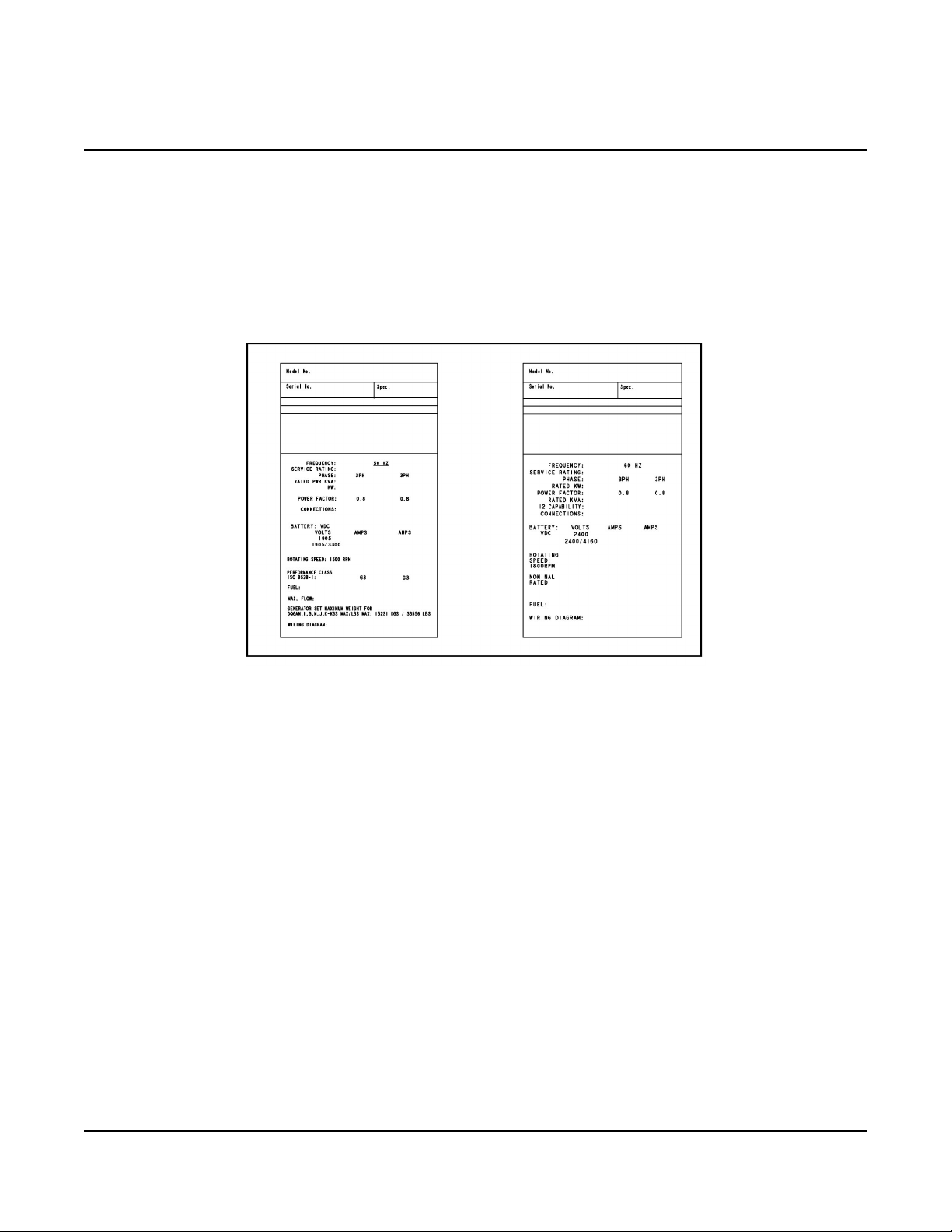
Each generator set is provided with a nameplate similar to that shown below. The nameplate provides
information unique to the generator set.
3.1.1 Nameplate
FIGURE 1. TYPICAL GENERATOR SET NAMEPLATE
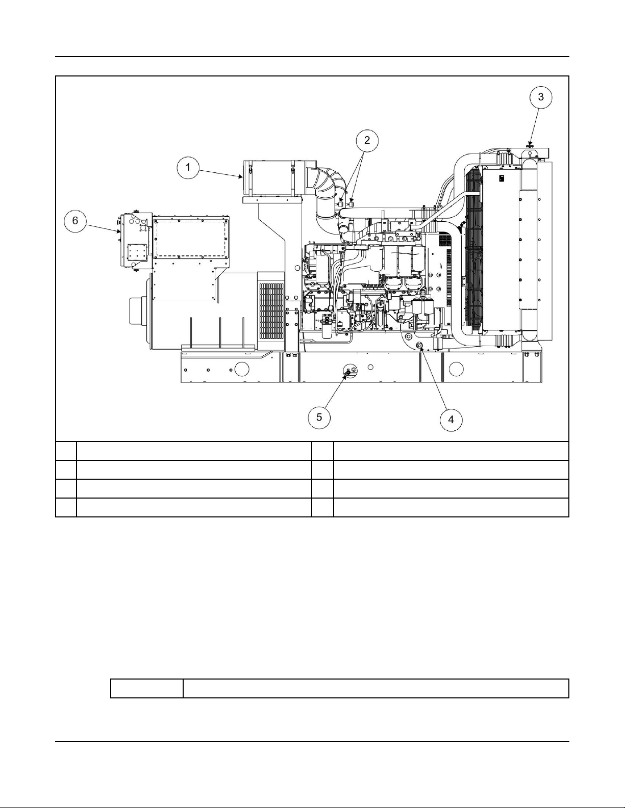
3.1.2 Generator Set Components
The main components of a QST30-G5 engine generator set are shown below, and referred to within this
section.
There are various options listed although they may not be available for all models.
19A053U867 (Issue 5) Copyright © 2019 Cummins Inc.
Page 26
3. System Overview 6-2019
No Description No Description
1 Air Cleaners 4 Coolant Drain
2 Air Cleaner Service Indicators 5 Oil Drain
3 Radiator Cap 6 Control Panel
FIGURE 2. GENERATOR SET COMPONENTS
3.2 Generator Set Rating
For details of the generator set rating, refer to the generator set nameplate. For operation at temperatures
or altitudes above those stated on the nameplate, a derate may be necessary.
3.3 Derating Factors
TABLE 1. DQFAA DERATING FACTOR
Application Derating Factor
20 A053U867 (Issue 5)Copyright © 2019 Cummins Inc.
Page 27

3. System Overview6-2019
Prime Engine power available up to 3150 m (10335 ft) at ambient temperatures up to 40 °C
(104 °F) and 2630 m (8628 ft) at ambient temperatures up to 50 °C (122 °F). Above
these elevations, derate at 3.5% per 305 m (1000 ft) and 7% per 10 °C (18 °F).
Standby Engine power available up to 3200 m (10500 ft) at ambient temperatures up to 40 °C
(104 °F) and 2200 m (7217 ft) at ambient temperatures up to 50 °C (122 °F). Above
these elevations, derate at 3.5% per 305 m (1000 ft) and 7% per 10 °C (18 °F).
TABLE 2. DQFAB DERATING FACTOR
Application Derating Factor
Prime Engine power available up to 2660 m (8727 ft) at ambient temperatures up to 40 °C
(104 °F) and 2090 m (6856 ft) at ambient temperatures up to 50 °C (122 °F). Above
these elevations, derate at 3.5% per 305 m (1000 ft) and 7% per 10 °C (18 °F)
Standby Engine power available up to 2700 m (8858 ft) at ambient temperatures up to 40 °C
(104 °F) and 1655 m (5429 ft) at ambient temperatures up to 50 °C (122 °F). Above
these elevations, derate at 3.5% per 305 m (1000 ft) and 7% per 10 °C (18 °F)
TABLE 3. DQFAC DERATING FACTOR
Application Derating Factor
Prime Engine power available up to 1650 m (5413 ft) at ambient temperatures up to 40 °C
(104 °F) and 975 m (3198 ft) at ambient temperatures up to 50 °C (122 °F). Above
these elevations, derate at 3.5% per 305 m (1000 ft) and 7% per 10 °C (18 °F).
Standby Engine power available up to 1720 m (5643 ft) at ambient temperatures up to 40 °C
(104 °F) and 595 m (1952 ft) at ambient temperatures up to 50 °C (122 °F). Above
these elevations, derate at 3.5% per 305 m (1000 ft) and 7% per 10 °C (18 °F)
TABLE 4. DQFAD DERATING FACTOR
Application Derating Factor
Prime Engine power available up to 727 m (2385 ft) at ambient temperatures up to 40 °C (104
°F). Above these elevations, derate at 3.5% per 305 m (1000 ft) and 7% per 10 °C (18
°F).
Standby Engine power available up to 701 m (2300 ft) at ambient temperatures up to 40 °C (104
°F). Above these elevations, derate at 3.5% per 305 m (1000 ft) and 7% per 10 °C (18
°F).
3.4 Engine Components
For additional engine specific information, refer to the relevant engine manual for the generator set.
21A053U867 (Issue 5) Copyright © 2019 Cummins Inc.
Page 28
3. System Overview 6-2019
No. Description No. Description
1 Crankcase Breather Tube (each side) 8 Fuel system
2 Thermostat Housing 9 Fuel Outlet
3 Temperature Sender 10 Oil Pan
4 Water Outlet Connection 11 Oil Drain
5 Exhaust Outlet 12 Oil Fill
6 Magnetic Switch 13 Oil Check
7 Starting Motor 14 Water Inlet Connection
FIGURE 3. ENGINE COMPONENTS
3.5 System Options
3.5.1 Introduction
This section provides information for system options that require installation or customer connections
before commissioning the generator set. For more information regarding system options, refer to the
operator and service manual.
3.5.2 Battery Charger
Battery chargers can be wall, bench, or skid mounted. For more information, see Section 9.13 on page
81.
22 A053U867 (Issue 5)Copyright © 2019 Cummins Inc.
Page 29

3.5.3 Day Tank
Some generator set installations include a fuel day tank. For more information, refer to Section 7.1.6 on
page 45.
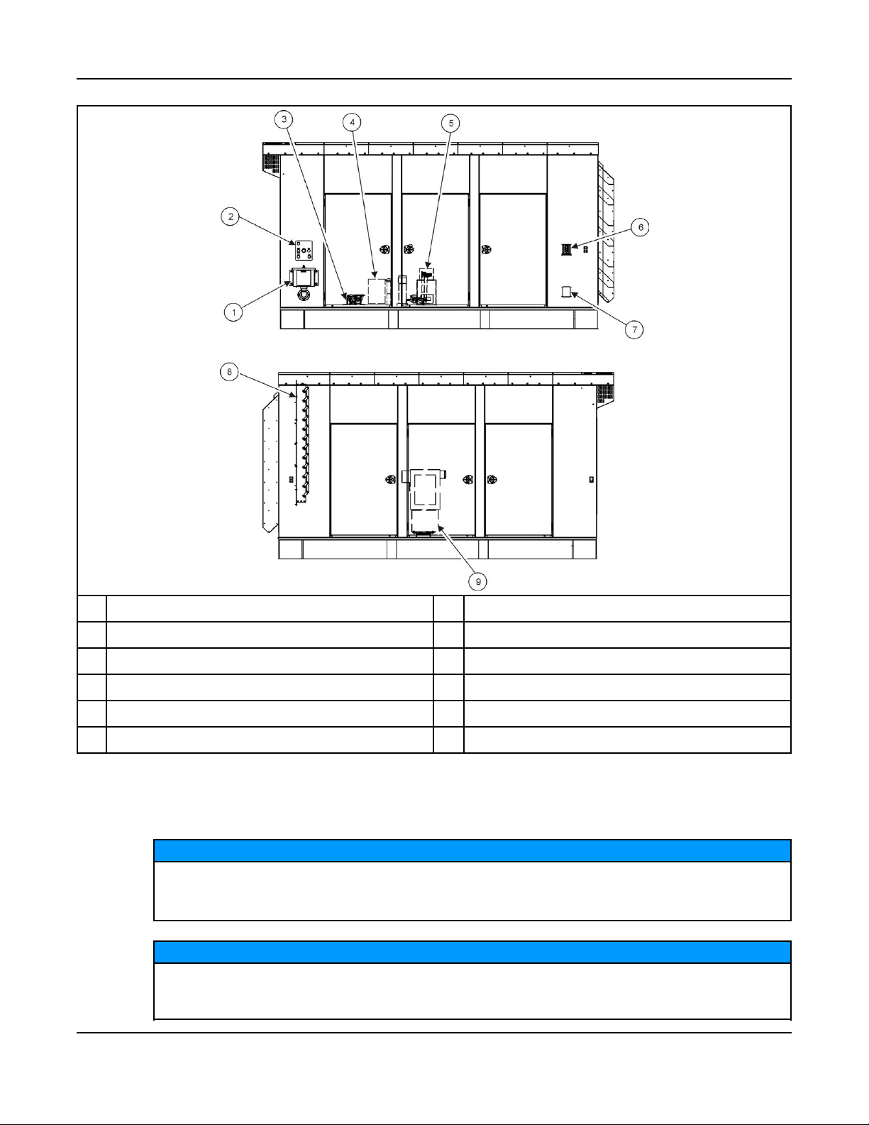
3.5.4 Enclosures
Enclosed generator sets can require optional features to be electrically connected during installation.
Use flexible conduit and stranded conductors for connections. Solid copper wire may break
during generator set operation.
3. System Overview6-2019
NOTICE
23A053U867 (Issue 5) Copyright © 2019 Cummins Inc.
Page 30
3. System Overview 6-2019
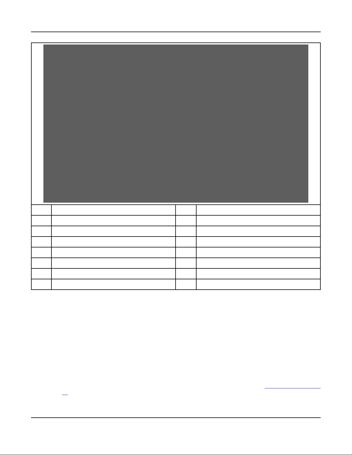
No. Description No. Description
1 External Fuel Fill Box 6 Emergency Stop Switch
2 Fuel Alarm Panel 7 120 VAC External Receptacle
3 Overfill Alarm Assembly 8 Motorized Inlet Louver
4 Fuel Fill 9 AC Distribution Panel
5 Fuel System Control
FIGURE 4. TYPICAL OPTIONAL ENCLOSURE FEATURES
3.5.5 Fuel Transfer Pump
NOTICE
Damage to the fuel transfer pump can occur if the pump operates with no fuel in the supply tank.
Do not connect AC power to the fuel transfer pump control without having fuel in the supply
tank.
NOTICE
Power to the fuel transfer pump must be fed from a transfer switch and step-down transformer to
maintain 120V power to the pump when utility power in interrupted. Power must be supplied to
the transfer pump during the time the generator set is running or not running.
24 A053U867 (Issue 5)Copyright © 2019 Cummins Inc.
Page 31

3. System Overview6-2019
The fuel pump/controller is pre-wired and ready to connect to a 120 VAC source.
NOTICE
When power is applied to the control or is restored after a power interruption, the control will
automatically go to the power on mode (functions the same as pressing the ON switch). The
pump starts if the control detects low fuel in the sub-base tank.
A fuel transfer pump and control are available when a sub-base fuel tank is provided. The automatic
control operates the fuel pump to maintain a reservoir of fuel in the sub-base tank.
The fuel transfer pump has a maximum inlet restriction capability of 16 inch Hg, which is approximately
equivalent to 20 feet of diesel.
No. Description No. Description
1 Overfill Alarm 3 Fuel System Control
2 Fuel Fill 4 Leads to 120 VAC Emergency Supply
FIGURE 5. FUEL TRANSFER PUMP/CONTROL LOCATION
3.5.6 Heaters
3.5.6.1 Heater Supply and Isolation
An external power supply is required for the operation of the generator set heaters.
NOTICE
If not already provided, it is the sole responsibility of the customer to provide the power supply
and the means to isolate the AC input to the terminal box. Cummins accepts no responsibility for
providing the means of isolation.
25A053U867 (Issue 5) Copyright © 2019 Cummins Inc.
Page 32

3. System Overview 6-2019
3.5.6.2 Alternator Heaters
Alternator heaters are used to help keep the alternator free of condensation when the generator set is not
running. For more information on alternator heater components and specifications, refer to Section 9.10
on page 75.
3.5.6.3 Coolant Heater
Coolant heaters heat the coolant to maintain a minimum engine temperature when the generator set is not
running. For more information on coolant heater components and specifications, see Section 9.9 on page
75.
3.5.6.4 Control Box Heater
A control box heater provides a means of humidity and temperature control of the control box interior. It
protects the components when the generator set is subjected to varying ambient air conditions during
extended periods of non-use. For more information on heater components and wiring, see Section 9.11
on page 75.
3.5.7 Remote Radiator Installation
Special requirements apply if your generator set includes a remote radiator. For more information, refer to
Section 7.7 on page 54.
3.5.8 Relays
3.5.8.1 Customer Relays
These relays are used for customer-specific applications. For more information, see Section 8.3 on page
63.
3.5.9 Seismic Installation Requirements
Seismically certified generator set installations have special requirements, as defined by IAA-VMC
(Independent Approval Agency, the VMC Group).
For special installation requirements, refer to the tabulated and written seismic requirements listed in the
Seismic Requirements appendix Appendix E on page 157 The installation of the seismically certified
generator set should be overseen by the installation project structural engineer of record.
The "Seismic Certificate of Compliance" should be kept with the Warranty and other generator set
documents.
The seismic requirements installation drawing and the Seismic Certificate of Compliance for generator
sets are included in the literature package of each seismically certified generator set.
3.5.10 Sensors
Various generator set parameters are measured by sensors, and the resulting signals are processed by
the control board.
Typical sensors include, but are not limited to:
• Oil pressure
• Coolant level
• Fuel level
• Coolant temperature
• Lube oil temperature
26 A053U867 (Issue 5)Copyright © 2019 Cummins Inc.
Page 33

• Alternator temperature
3.5.10.1 Pyrometers - Engine Exhaust
A pyrometer measures engine exhaust gas temperature. A separate temperature meter is used to monitor
each exhaust outlet elbow.
3.5.10.1.1 Pyrometer Position
3. System Overview6-2019
No. Description No Description
1 Temperature Meter 3 Temperature Sender
2 Exhaust Outlet Elbows
FIGURE 6. PYROMETER LOCATION AND METER
27A053U867 (Issue 5) Copyright © 2019 Cummins Inc.
Page 34

3. System Overview 6-2019
This page is intentionally blank.
28 A053U867 (Issue 5)Copyright © 2019 Cummins Inc.
Page 35

4 Installation Overview
These installation recommendations apply to typical installations with standard model generator sets.
Whenever possible, these recommendations also cover factory designed options or modifications.
However, because of the many variables in any installation, it is not possible to provide specific
recommendations for every situation. If there are any questions not answered by this manual, contact your
nearest authorized distributor for assistance.
4.1 Application and Installation
A power system must be carefully planned and correctly installed for proper operation. This involves two
essential elements.
• Application (as it applies to generator set installations) refers to the design of the complete power
system that usually includes power distribution equipment, transfer switches, ventilation equipment,
mounting pads, cooling, exhaust, and fuel systems. Each component must be correctly designed so
the complete system will function as intended. Application and design is an engineering function
generally done by specifying engineers or other trained specialists. Specifying engineers or other
trained specialists are responsible for the design of the complete power system and for selecting the
materials and products required.
• Installation refers to the actual set-up and assembly of the power system. The installers set up and
connect the various components of the system as specified in the system design plan. The
complexity of the system normally requires the special skills of qualified electricians, plumbers,
sheet-metal workers, etc. to complete the various segments of the installation. This is necessary so
that all components are assembled using standard methods and practices.
4.2 Safety Considerations
The generator set has been carefully designed to provide safe and efficient service when properly
installed, maintained, and operated. However, the overall safety and reliability of the complete system is
dependent on many factors outside the control of the generator set manufacturer. To avoid possible safety
hazards, make all mechanical and electrical connections to the generator set exactly as specified in this
manual. All systems external to the generator (fuel, exhaust, electrical, etc.) must comply with all
applicable codes. Make certain all required inspections and tests have been completed and all code
requirements have been satisfied before certifying the installation is complete and ready for service.
WARNING
Fall Hazard
Falls can result in severe personal injury or death.
Make sure that suitable equipment for performing tasks at height are used in accordance with
local guidelines and legislation.
4.3 Standby Heating Devices
Cummins requires installing standby generator sets (life safety systems) with engine jacket water coolant
heaters in order to ensure a 10 second start. Jacket water coolant heaters are also recommended in
prime and continuous applications where time and load acceptance is to be minimized.
29A053U867 (Issue 5) Copyright © 2019 Cummins Inc.
Page 36

4. Installation Overview 6-2019
The jacket water coolant heater provided by Cummins rated to provide the above requirements in ambient
temperatures as low as 4 °C (40 °F). Although most Cummins generator sets will start in temperatures
down to –32 °C (–25 °F) when equipped with engine jacket water coolant heaters, it might take more than
10 seconds to warm the engine before a load can be applied when ambient temperatures are below 4 °C
(40 °F).
On generator sets equipped with a graphic display, the Low Coolant Temperature message, in
conjunction with illumination of the Warning LED, is provided to meet the current requirements. The
engine cold sensing logic initiates a warning when the engine jacket water coolant temperature falls below
21 °C (70 °F). In applications where the ambient temperature falls below 4 °C (40 °F), or there exists a
high amount of cold airflow, the jacket water coolant heater may not provide the necessary heating. Under
these conditions, although the generator set may start, it may not be able to accept load within 10
seconds. When this condition occurs, check the coolant heaters for proper operation. If the coolant
heaters are operating properly, other precautions may be necessary to warm the engine before applying a
load.
4.4 Product Modifications
Agency certified products purchased from Cummins comply only with those specific requirements and as
noted on company product specification sheets. Subsequent modifications must meet commonly accepted
engineering practices and/or local and national codes and standards. Product modifications must be
submitted to the local authority having jurisdiction for approval.
4.5 De-Rating Factors
Engine power and resulting electrical output decrease as ambient temperature or altitude increases. For
de-rating factors applicable at specific sites, contact your authorized distributor.
30 A053U867 (Issue 5)Copyright © 2019 Cummins Inc.
Page 37

5 Specifications
5.1 Generator Set Specifications
TABLE 5. DQFAA, DQFAB, DQFAC, AND DQFAD SPECIFICATIONS
MODELS DQFAA DQFAB DQFAC DQFAD
Engine
Cummins Diesel Series QST30-G5 QST30-G5 QST30-G5 QST30-G5
Generator kW Rating (Standby /
Prime)
Engine Fuel Connection
Inlet/Outlet Thread Size Refer to generator set outline drawing
Maximum Weight
AKG Cooling Package 15539 lbs
Bearward Cooling Package 15363 lbs
Fuel
Max. Fuel Inlet Restriction 8 inHg
Max. Fuel Return Restriction with Set
Mounted Radiator
Max. Fuel Return Restriction with
Remote Radiator
Fuel Pump Flow Rate 150 gal/hr
750/680 800/725 900/818 1000/900
(7048 kg)
(6971 kg)
(27 kPa)
20 inHg
(67.5 kPa)
20 inHg
(67.5 kPa)
(570 L/hr)
16555 lbs
(7509 kg)
15855 lbs
(7194 kg)
8 inHg
(27 kPa)
20 inHg
(67.5 kPa)
20 inHg
(67.5 kPa)
150 gal/hr
(570 L/hr)
16720 lbs
(7584 kg)
16910 lbs
(7672 kg)
8 inHg
(27 kPa)
20 inHg
(67.5 kPa)
20 inHg
(67.5 kPa)
150 gal/hr
(570 L/hr)
16910 lb
(7670 kg)
17480 lb
(7931 kg)
8 inHg
(27 kPa)
20 inHg
(67.5 kPa)
20 inHg
(67.5 kPa)
150 gal/hr
(570 L/hr)
Exhaust
Outlet Size 6 in. NB 6 in. NB 6 in. NB 6 in. NB
Max. Allowable Back Pressure 27 in. H2O
(6.8 kPa)
Exhaust Flow at Rated Load 6310 cfm
(177 m3/min)
Exhaust Temperature 816 °F
(435 °C)
Electrical System
Starting Voltage 24 Volts DC 24 Volts DC 24 Volts DC 24 Volts DC
Battery Group Number 8D 8D 8D 8D
27 in. H2O
(6.8 kPa)
6550 cfm
(183 m3/min)
833 °F
(445 °C)
27 in. H2O
(6.8 kPa)
6950 cfm
(195 m3/min)
866 °F
(463 °C)
27 in. H2O
(6.8 kPa)
7540 cfm
(211 m3/min)
890 °F
(477 °C)
31A053U867 (Issue 5) Copyright © 2019 Cummins Inc.
Page 38

5. Specifications 6-2019
MODELS DQFAA DQFAB DQFAC DQFAD
CCA (minimum) 1400 1400 1400 1400
Cooling System
Capacity with AKG Set-mounted 50 °C
Radiator
Capacity with Bearward Set-mounted 50
°C Radiator
Airflow: AKG manufactured prior to Sept
2016
Airflow: AKG manufactured post Sept
2016
Airflow: Bearward 35000 cfm
Lubricating System
Oil Capacity with Filters 162.8 qt
44.08 US gal
(166.86 L)
53.2 US gal
(201 L)
54929 cfm
(1555 m3/min)
39900 cfm
(1130 m3/min)
(991 m3/min)
(154 L)
5.2 Engine Fuel Consumption
TABLE 6. FUEL CONSUMPTION AT 1800 RPM (60 HZ)
QST30 Engine
44.08 US gal
(166.86 L)
53.2 US gal
(201 L)
54929 cfm
(1555 m3/min)
39900 cfm
(1130 m3/min)
35000 cfm
(991 m3/min)
162.8 qt
(154 L)
44.08 US gal
(166.86 L)
53.2 US gal
(201 L)
54929 cfm
(1555 m3/min)
39900 cfm
(1130 m3/min)
35000 cfm
(991 m3/min)
162.8 qt
(154 L)
44.08 US gal
(166.86 L)
53.2 US gal
(201 L)
54929 cfm
(1555 m3/min)
39900 cfm
(1130 m3/min)
35000 cfm
(991 m3/min)
162.8 qt
(154 L)
Model DQFAA DQFAB DQFAC DQFAD
Standby 199.5 L/Hr
(52.7 US GPH)
Prime 181.3 L/Hr
(47.9 US GPH)
Note: Fuel Consumption at Full Load, refer to Data Sheets for other applications. In line with the CPG
policy of continuous improvement, these figures are subject to change.
213.5 L/Hr
(56.4 US GPH)
193.1 L/Hr
(51.0 US GPH)
241.9 L/Hr
(63.9 US GPH)
218.4 L/Hr
(57.7 US GPH)
273.3 L/Hr
(72.2 US GPH)
241.9 L/Hr
(63.9 US GPH)
32 A053U867 (Issue 5)Copyright © 2019 Cummins Inc.
Page 39

6 Installing the Generator Set
Generator set installations must be engineered so that the generator set will function properly under the
expected load conditions. Use these instructions as a general guide only. Follow the instructions of the
consulting engineer when locating or installing any components. The complete installation must comply
with all local and state building codes, fire regulations, and other applicable regulations.
Requirements to be considered prior to installation are:
• Level mounting surface
• Adequate cooling air
• Adequate fresh induction air
• Discharge of generator set air
• Non-combustible mounting surface
• Discharge of exhaust gases
• Electrical connections
• Accessibility for operation and servicing
• Noise levels
• Vibration isolation
NOTICE
Depending on the location and intended use, ensure that international, national or local laws and
regulations regarding Air Quality Emissions have been observed and complied with. Be sure to
consult local pollution control or air quality authorities before completing construction plans.
6.1 Transportation
Heavy Load
Incorrect lifting or repositioning can cause severe personal injury or death.
Make sure that only suitably trained and experienced personnel transport and handle generator
sets and associated components.
Heavy Load
Incorrect lifting or repositioning can cause severe personal injury or death.
Do not lift the generator set by attaching to the engine or alternator lifting points. Do not stand
under or near the generator set when lifting.
WARNING
WARNING
33A053U867 (Issue 5) Copyright © 2019 Cummins Inc.
Page 40

6. Installing the Generator Set 6-2019
NOTICE
Any panels or doors must be locked before re-positioning and must remain locked during
transportation and siting.
• Ensure the generator set is prepared for transport. If necessary drain fluids and ensure that acid or
fumes do not leak from the battery (where applicable).
• If the generator set is transported over long distances, protect it against environmental influences by
sealing it in a plastic cover or similar.
• Ensure the generator set is secured to the vehicle with suitable securing straps. Wooden chocks and
pallets alongside the securing straps can prevent movement during transportation.
• If required, attached impact indicators to the generator set. Upon delivery, check these impact
indicators and contact the transport company immediately if an impact has been detected. Impacts
can cause serious damage to the generator set and its components.
• Ensure that the generator set cannot turn over during transportation.
• Do not overload the transport vehicle. Under no circumstances should the generator set be started
while inside a truck.
• Lifting eyes, where fitted, are to be checked at regular intervals to ensure they are damage free and
tight.
6.2 Location
Electrical Generating Equipment
Incorrect operation and maintenance can result in severe personal injury or death.
Make sure that only suitably trained and experienced service personnel perform electrical and/or
mechanical service.
Incorrect installation
Incorrect installation of the generator set, service or parts replacement, can result in severe
personal injury, death, and/or equipment damage.
Service personnel must be trained and experienced to perform electrical and mechanical
component installation.
Depending on your location and intended use, additional laws and regulations may require for
you to obtain an air quality emissions permit before beginning installation of your generator set.
Be sure to consult local pollution control or air quality authorities before completing your
construction plans.
WARNING
WARNING
NOTICE
Generator set location is decided mainly by related systems such as ventilation, wiring, fuel, and exhaust.
The set should be located as near as possible to the main power service entrance. Exhaust gases must
not be able to enter or accumulate around inhabited areas.
Provide a location away from extreme ambient temperatures and protect the generator set from adverse
weather conditions.
Use the following information to locate the generator set for optimal operating conditions:
34 A053U867 (Issue 5)Copyright © 2019 Cummins Inc.
Page 41

Surface: Concrete or compacted gravel with the generator set resting on solid, poured concrete blocks, or
timber blocks spaced at reasonable intervals around the perimeter of the generator set.
Leveling: Level the generator set from side-to-side within + 3.5°, and end-to-end within +2.5°.
Placement:
• Generator sets should be a minimum of 5 m (16.4 ft) apart to allow for adequate access.
• Make sure that the air inlets are not obstructed by surrounding trees, buildings, or other obstructions.
• Make sure noise distribution (to prevent echoing) is kept to a minimum.
• Consider exhaust for immediate neighbors.
• The prevailing wind direction should be considered so that the engine combustion air inlet is upwind
and the exhaust discharge is downwind.
• The immediate area around the proposed location of the mounting surface should be evaluated for
proper drainage so that moisture run-off is sufficient to prevent ponding around the unit(s).
6.3 Moving the Generator Set
WARNING
Heavy Load
Incorrect lifting or repositioning can cause severe personal injury or death.
Make sure that only suitably trained and experienced personnel transport and handle generator
sets and associated components.
6. Installing the Generator Set6-2019
WARNING
Heavy Load
Incorrect lifting or repositioning can cause severe personal injury or death.
Do not lift the generator set by attaching to the engine or alternator lifting points. Do not stand
under or near the generator set when lifting.
WARNING
Mechanical Hazard
Failed components may be ejected or operate incorrectly which can cause severe personal injury
or death.
Do not climb the generator set; this may damage critical parts.
NOTICE
Make sure that any shipping brackets supplied with the generator set are fitted, before moving
the generator set. Failure to install the shipping brackets before moving may result in damage to
the generator set.
NOTICE
Access or service doors must be closed and locked before repositioning, and they must remain
locked during transportation and siting.
35A053U867 (Issue 5) Copyright © 2019 Cummins Inc.
Page 42

6. Installing the Generator Set 6-2019
It is essential that there are sufficient trained and experienced personnel in attendance to make sure the
lifting and transportation of the generator set is undertaken in a safe and appropriate manner, and in
accordance to local guidelines and legislation.
Before lifting the generator set, lifting points, angle of slings, mass, access to intended site, and the
distance of movement should all be taken into account when organizing a suitable crane/hoist. Consult the
generator set information supplied with the generator set for details of dimensions and mass.
• Make sure the genset is not having fuel in the fuel tank of the generator set.
• Make sure that the crane operating area is able to support the mass of the crane and the generator
set.
• Make sure the equipment used for lifting is adequate to support the weight of the generator set.
• Attach the lifting device to the lifting points only using suitable shackles, chains, and spreader bars.
• Slowly tighten the slings. Inspect the lifting attachments before commencing a full lift to make sure
they are attached correctly.
• Hoist the generator set slowly using the indicated lifting points only.
• Guide the generator set with ropes at a safe distance to prevent uncontrolled rotation when
positioning the generator set.
• Move the generator set to the desired location and place in position, bringing the set down slowly.
• Loosen the slings; unhook and remove the shackles.
6.3.1 Rigging Instructions
Heavy Load
Incorrect lifting or repositioning can cause severe personal injury or death.
Do not lift the generator set by attaching to the engine or alternator lifting points. Do not stand
under or near the generator set when lifting.
Heavy Load
Incorrect lifting or repositioning can cause severe personal injury or death.
Make sure that only suitably trained and experienced personnel transport and handle generator
sets and associated components.
1. Consult the generator set outline drawing for weight and center-of-gravity information.
2. Attach cables from the lifting lugs to a spreader bar. Never make the spreader bar cable attachment
points wider than the attachment points on the skid or the bars. Make sure cables do not touch any
other part of the generator set other than the skid.
Spreader bar cable attach points width "Y" must never be wider than skid cable attach
points "X." Distance "X" is the narrowest width.
WARNING
WARNING
NOTICE
NOTICE
Angle B must be slightly greater than angle A. Angle B should be as close to 90 degrees as
possible to provide a stable lift.
36 A053U867 (Issue 5)Copyright © 2019 Cummins Inc.
Page 43

6. Installing the Generator Set6-2019
3. With pedestal box (not shown), the spreader bars (front and back) should be used to clear the
pedestal box and the attachment cables must be as vertical as possible.
NOTICE
The lifting angle (angle C) must not exceed 20° from vertical.
Item Description No. Description
A Angle A 1 Spreader Bar
B Angle B 2 Lifting Point
C Angle C (20° Maximum) 3 Lifting Cables
X The Narrowest Width (On the Skid) 4 Center of Gravity
Y This Distance Must be Less than Distance "X"
FIGURE 7. RIGGING
6.4 Mounting
Generator sets are mounted on a steel skid that provides proper support, which is sited on mechanical
spring isolators to provide adequate vibration isolation per application.
NOTICE
The use of unapproved isolators may result in harmful resonances and may void the generator
set warranty.
Mount the generator set on a substantial and level base such as a concrete pad. A non-combustible
material must be used for the pad.
37A053U867 (Issue 5) Copyright © 2019 Cummins Inc.
Page 44

6. Installing the Generator Set 6-2019
The fixing centers for the mounting bolts can be found on the generator set Outline Drawing referenced in
Appendix C on page 121
6.5 Access to Generator Set
Generally, at least 1 meter (3.3 ft) of clearance should be provided on all sides of the generator set for
maintenance and service access. (Increase clearance by width of door if optional housing is used.) A
raised foundation or slab of 152 mm (6 inches) or more above floor level will make servicing easier.
Lighting should be adequate for operation, maintenance and service operations and should be connected
on the load side of the transfer switch so that it is available at all times.
6.6 Seismic Installation Notes
1. The design of post-installed anchors in concrete used for the component anchorage is pre-qualified
for seismic applications in accordance with "ACI 355.2" and documented in a report by a reputable
testing agency. (ex. the evaluation service report issued by the International Code Council)
2. Anchors must be installed to an embedment depth as recommended in the pre-qualification test
report as defined in Note 1. For "IBC 2000" and "IBC 2003" applications, the minimum embedment
must be 8X for the anchor diameter.
3. Anchors must be installed in minimum 4000 PSI compressive strength normal weight concrete.
Concrete aggregate must comply with "ASTM C33". Installation in structural lightweight concrete is
not permitted unless otherwise approved by the structural engineer of record.
4. Anchors must be installed to the torque specification as recommended by the anchor manufacturer
to obtain maximum loading.
5. Anchors must be installed in locations specified in this section.
6. Wide washers must be installed at each anchor location between the anchor head and equipment for
tension load distribution. Wide washers must be Series "W" of American National Standard Type "A"
plain washers (ANSI B18.22.1-1965, R1975) with the nominal washer size selected to match the
specified nominal anchor diameter.
7. Concrete floor slab and concrete housekeeping pads must be designed and rebar reinforced for
seismic applications in accordance with "ACI 318". The design loads shall be taken as those
specified in this section.
8. All housekeeping pad thicknesses must be designed in accordance with the pre-qualification test
report as defined in Note 1 or a minimum of 1.5X the anchor embedment depth, whichever is largest.
9. All housekeeping pads must be dowelled or cast into the building structural floor slab and designed
for seismic application per "ACI 318" and as approved by the structural engineer of record.
10. Wall mounted equipment must be installed to a rebar reinforced structural concrete wall that is
seismically designed and approved by the engineer of record to resist the added seismic loads from
components being anchored to the wall.
11. Floor mounted equipment (with or without a housekeeping pad) must be installed to a rebar
reinforced structural concrete floor that is seismically designed and approved by the engineer of
record to resist the added seismic loads from components being anchored to the floor.
12. When installing to a floor or wall, rebar interference must be considered.
13. Attaching seismic certified equipment to any floor or wall other than those constructed of structural
concrete and designed to accept the seismic loads from said equipment is not permitted by this
specification and beyond the scope of this certification.
14. Attaching seismic certified equipment to any floor constructed of light weight concrete over steel
decking is not permitted by this specification and beyond the scope of this certification.
38 A053U867 (Issue 5)Copyright © 2019 Cummins Inc.
Page 45

6. Installing the Generator Set6-2019
15. Attaching the seismic certified equipment to any concrete block walls or cinder block walls is not
permitted by this specification and beyond the scope of this certification.
16. Installation upon a rooftop steel dunnage shall be coordinated with the structural engineer of record.
17. Installation upon any rooftop curb shall be coordinated with the curb manufacturer and the structural
engineer of record. Any curb or concrete pad that supports the generator set unit is beyond the
scope of this certification.
18. Connections to the equipment, including but not limited to conduit, wiring from cable trays, other
electrical services, ducting, piping such as exhaust, steam, water, coolant, refrigerant, fuel, or other
connections, are the responsibility of the installing contractor and beyond the scope of this
document. Typical requirements for these connections are stated in the equipment installation
manual. Special considerations for seismic applications are as follows; connections to non-isolated
components or equipment may be installed as typical for that particular application. Connections to
isolated components (ex. breaker box bolted directly to an isolated generator set) or isolated
equipment (ex. an enclosed generator set mounted on external isolators) must be flexibly attached.
The flexible attachment must provide for enough relative displacement to remain connected to the
equipment and functional during and after a seismic event.
39A053U867 (Issue 5) Copyright © 2019 Cummins Inc.
Page 46

6. Installing the Generator Set 6-2019
This page is intentionally blank.
40 A053U867 (Issue 5)Copyright © 2019 Cummins Inc.
Page 47

7 Mechanical Connections
The generator set mechanical system installation includes connecting the fuel, exhaust, ventilation, and
cooling systems. Before starting any type of fuel installation, all pertinent state and local codes must be
complied with and the installation must be inspected before the unit is put in service.
7.1 Fuel System
Cummins engines normally use a diesel fuel specified to ASTM D975 grade 2 or BS EN 590:2000 is for
automotive diesel, BS 2869:2010+A1:2011 Fuel oils for agricultural, domestic and industrial engines and
boilers.
In all fuel system installations, cleanliness is of the utmost importance. Make every effort to prevent
entrance of moisture, dirt, or contaminants of any kind into the fuel system. Clean all fuel system
components before installing.
NOTICE
A fuel filter/strainer/water separator of 100-120 mesh or equivalent (approximately 150 microns
nominal) must be fitted between either the main tank and day tank, or between the main tank and
the engine.
Use only compatible metal fuel lines to avoid electrolysis when fuel lines must be buried. Buried fuel lines
must be protected from corrosion.
NOTICE
Never use galvanized or copper fuel lines, fittings, or fuel tanks. Condensation in the tank and
lines combines with the sulfur in diesel fuel to produce sulfuric acid. The molecular structure of
the copper or galvanized lines or tanks reacts with the acid and contaminates the fuel.
An electric solenoid valve in the supply line is recommended for all installations and required for indoor
automatic or remote starting installations. Connect the solenoid wires to the generator set “Switched B+”
circuit to open the valve during generator set operation.
Separate fuel return lines to the day tank or supply tank must be provided for each generator set in a
multiple-set installation to prevent the return lines of idle sets from being pressurized. Fuel return lines
must not contain a shutoff device. Engine damage will occur if the engine is run with the return fuel lines
blocked or restricted.
NOTICE
Never install a shutoff device in fuel return line(s). If fuel return line(s) is blocked or exceeds fuel
restriction limit, engine damage will occur.
NOTICE
A base mounted fuel tank may be part of the generator set build. An additional external fuel
system may be required if the on board fuel capacity is not sufficient for the application.
41A053U867 (Issue 5) Copyright © 2019 Cummins Inc.
Page 48

7. Mechanical Connections 6-2019
7.1.1 Fuel Return Restrictions (or Pressure) Limit
Fuel return drain restriction (consisting of friction head and static head) between the engine injector return
line connection and the fuel tank must not exceed the limit stated in the model-specific generator set
Specification Sheet.
7.1.2 Fuel Line Connections
WARNING
Combustible Liquid
Fuel leaks are a fire and explosion hazard which can cause severe personal injury or death.
Always use flexible tubing between the engine and fuel supply to avoid line failure and leaks due
to vibration. The fuel system must meet all application codes.
WARNING
Combustible Liquid
Ignition of fuel is a fire and explosion hazard which can cause severe personal injury or death.
Do not route fuel lines near electrical wiring.
WARNING
Hot Surface
Hot surfaces can ignite fuel. Ignited fuel is a fire and explosion hazard which can cause severe
burns or death.
Do not route fuel lines near hot exhaust parts.
NOTICE
Fuel lines must be routed and secured to maintain a 12.7 mm (½ inch) minimum clearance from
electrical wiring and a 51 mm (2 inches) minimum clearance from hot exhaust parts.
Flexible lines for connecting between the engine and the skid mounted fuel tank (if fitted) are supplied as
standard equipment.
Flexible lines for connecting between the engine and an external fuel supply must be used between the
engine fuel system, and the fuel supply and return lines to protect the fuel system from damage caused by
vibration, expansion, and contraction.
For additional information refer to T-030 Application Manual.
42 A053U867 (Issue 5)Copyright © 2019 Cummins Inc.
Page 49

7. Mechanical Connections6-2019
No. Description No. Description
1 Day Tank/Skid Mounted Fuel Tank 9 Fill Pipe
2 Engine Fuel Pump 10 Main Fuel Tank
3 Shut Off Valve 11 Supply Line
4 Float Switch 12 Larger Overflow Line 120 Mesh Fuel Strainer
5 Vented Fill Cap 13 120 Mesh Fuel Strainer
6 Injector Fuel Return Line 14 Fuel Transfer Pump Electric Motor Driven
7 Connect to AC Output 15 Baffle
8 Vent Pipe 16 25.4 mm (1 inch) Clearance
FIGURE 8. TYPICAL FUEL SUPPLY INSTALLATION
7.1.3 Engine Fuel Connections
Identification tags are attached to the fuel supply line and fuel return line connections. All models require a
fuel return line from the injectors to the tank.
43A053U867 (Issue 5) Copyright © 2019 Cummins Inc.
Page 50

7. Mechanical Connections 6-2019
No. Description No. Description
1 Fuel Inlet 2 Fuel Outlet
Refer to Appendix C for the dimensional location of fuel line connections
FIGURE 9. FUEL CONNECTION LOCATIONS
TABLE 7. FUEL CONNECTION GUIDELINES
Fuel Inlet Fuel Outlet
Connection Size
Hose Type Eaton 1503 or Equivalent Eaton 1503 or Equivalent
Max Restriction Refer to Chapter 5
1-1/16-12UNF - 2A with 37° TIP 7/8-14UNF - 2A with 37°deg
7.1.4 Supply Tank
The fuel supply tank, day tank, or other reservoir must be arranged so that the highest fuel level does not
exceed the maximum height above the fuel injectors specified for the engine. The lowest level must not
fall below the specified lift height of the engine fuel lift pump. In critical start applications, the lowest level
should not be less than 150 mm (6 inches) above the engine fuel pump inlet to make sure there is no air
in the fuel line during startup. Provisions must be made for draining or pumping out water.
For critical start applications, where generator sets are paralleled or must satisfy emergency start-time
requirements, it is recommended that a fuel tank or reservoir be located such that the lowest possible fuel
level is not less than 150 mm (6 in) above the fuel pump inlet. This will prevent air from accumulating in
the fuel line while the generator set is in standby, eliminating the period during startup when it has to be
purged.
Locate the fuel tank as close as possible to the generator set and within the restriction limitations of the
fuel pump.
Install a fuel tank that has sufficient capacity to supply the generator set depending on its application:
• Continuous power
• Prime power
• Standby power
Refer to the Engine Fuel Consumption section for fuel consumption data.
44 A053U867 (Issue 5)Copyright © 2019 Cummins Inc.
Page 51

If the fuel inlet restriction exceeds the defined limit due to the distance/customer-supplied plumbing
between the generator set and the main fuel tank, a transfer tank (sometimes referred to as a day tank)
and auxiliary pump will also be required. If an overhead main fuel tank is installed, a transfer tank and float
valve will be required to prevent fuel head pressures from being placed on the fuel system components.
For additional information on the size and installation of a supply tank for the application, consult your
local authorized Cummins distributor or dealer.
7.1.5 Fuel Inlet Pressure/Restriction Limit
Engine performance and fuel system durability is compromised if the fuel inlet pressure or restriction limits
are not adhered to. Fuel inlet pressure or restriction must not exceed the limits stated in the model-specific
generator set Specification Sheet.
7.1.6 Day Tank
Some generator set installations may include a fuel day tank. They are used when fuel inlet restriction
limits cannot be met, or the supply tank is overhead and presents problems of high fuel head pressure for
the fuel inlet and return lines.
7.1.6.1 Supply Tank Lower Than Engine
WARNING
7. Mechanical Connections6-2019
Combustible Liquid
Spilled fuel is a fire and explosion hazard which can cause severe personal injury or death.
Provide an overflow line to the supply tank from the day tank.
NOTICE
The supply tank top must be below the day tank top to prevent siphoning from the fuel supply to
the day tank.
With this installation, the day tank is installed near the generator set, below the fuel injection system and
within the fuel inlet restriction limit. Install a fuel transfer pump, to pump fuel from the supply tank to the
day tank. A float switch in the day tank controls operation of the auxiliary fuel pump.
Provide a return line from the engine injection system return connection to the day tank. Plumb the return
line to the bottom of day tank as shown in Figure 8 on page 43. Provide a day tank overflow line to the
supply tank in case the float switch fails to shut off the fuel transfer pump.
7.1.6.2 Supply Tank Higher Than Engine
With this installation, the day tank is installed near the generator set, above the fuel injection system and
within the fuel return restriction limit. Include an automatic fuel shutoff valve in the fuel line between the
fuel supply tank and the day tank to stop fuel flow when the generator set is off.
Provide a return line from the engine injection system return connection to the day tank. Plumb the return
line to the bottom of day tank as shown in Figure 8 on page 43.
NOTICE
Spilled fuel can create environmental hazards. Check local requirements for containment and
prevention of draining to sewer and ground water.
45A053U867 (Issue 5) Copyright © 2019 Cummins Inc.
Page 52

7. Mechanical Connections 6-2019
7.1.7 Fuel Transfer Pump
7.1.7.1 Fuel Transfer Pump Installation
WARNING
Combustible Liquid
Fuel leaks are a fire and explosion hazard which can cause severe personal injury or death.
Make sure that only trained and experienced personnel install and service the generator set in
accordance with applicable codes.
NOTICE
Do not smoke near fuel and keep flames, sparks, pilot lights, arcing switches and equipment, and
other sources of ignition well away.
A fuel transfer pump and control are available as an option when a sub-base or an in-skid day tank is
provided. The automatic control operates the fuel pump to maintain a reservoir of fuel in the day tank.
7.1.7.1.1 Sub-Base Installation
No. Description No. Description
1 Float Switch Assembly 3 Fuel Supply Line
2 Fuel Fill Cap 4 Fuel Flexible Return Line
FIGURE 10. TYPICAL SUB-BASE INSTALLATION
7.1.8 Fuel Additives
NOTICE
It is the responsibility of the user to ensure that the correct additives and installation of an
external fuel supply is designed to meet the local climate conditions.
46 A053U867 (Issue 5)Copyright © 2019 Cummins Inc.
Page 53

Cummins engines are designed, developed, rated, and built to operate on commercially available diesel
fuel, therefore, it is not our policy to recommend fuel additives. However in certain situations, when
available fuels are of poor quality or problems exist which are peculiar to certain operations or climate
conditions, additives can be used. Consult with the fuel supplier and your local distributor prior to the use
of fuel additives.
7.2 Exhaust System
Toxic Gases
Inhalation of exhaust gases can cause asphyxiation and death.
Use extreme care during installation to provide a tight exhaust system. Terminate exhaust pipes
away from enclosed or sheltered areas, windows, doors, and vents. Do not use exhaust heat to
warm a room, compartment, or storage area.
Hot Surface
Hot surfaces can start a fire which can cause severe burns or death.
Use an approved thimble where exhaust pipes pass through wall or partitions.
7. Mechanical Connections6-2019
WARNING
WARNING
NOTICE
Weight applied to the engine manifold can result in turbocharger damage. Support the silencer
and exhaust piping so no weight or stress is applied to the engine exhaust elbow.
NOTICE
Gaseous fuels are susceptible to high condensation levels in the exhaust. It is important to have
properly routed/sized exhaust systems to prevent harm to turbochargers and Oxygen sensors
(HEGO).
NOTICE
Liability for injury, death, damage, and warranty expense due to use of unapproved silencers or
modifications to the exhaust system becomes the responsibility of the person installing the
unapproved silencer or performing the modification. Contact your authorized distributor for
approved exhaust system parts.
Pipe exhaust gases to the outside of any enclosure. Locate the exhaust outlets away from any air inlets to
avoid gases re-entering the enclosure. Exhaust installations are subject to various detrimental conditions
such as extreme heat, infrequent operation, and light loads. Regularly inspect the exhaust system both
visually and audibly to see that the entire system remains fume tight and safe for operation.
NOTICE
Enclosed generator sets are not generally designed to be used in a building. If the generator set
is to be used in a building, additional requirements must be applied.
47A053U867 (Issue 5) Copyright © 2019 Cummins Inc.
Page 54

7. Mechanical Connections 6-2019
Where an enclosed generator set is used in a building, the exhaust system should be extended to vent the
exhaust gases. Use sealed joint type fittings where possible to provide a tight exhaust system. Use of slip
type fittings (secured with a clamp) may allow leakage of exhaust gases into the building if not fitted
correctly. Check to make sure there are no exhaust leaks.
When a unit is provided with a partially installed or incomplete exhaust system, exhaust piping and
chimneys shall be designed, constructed, and installed in accordance with the Standard for the Installation
and Use of Stationary Combustion Engines and Gas Turbines, NFPA 37, or applicable local standards.
Build according to the code requirements in effect at the installation site.
For indoor installation, the exhaust system should use sealed joint type fittings where possible to provide a
tight exhaust system. Use of slip type fittings (secured with a clamp) may allow leakage of exhaust gases
into the building if not fitted correctly fitted. Check to make sure there are no exhaust leaks.
Use an approved thimble (see Figure 11 on page 49) where exhaust pipes pass through a wall or
partition. Insulated wall/roof thimbles are used where exhaust pipes pass through a combustible roof or
wall. This includes structures, such as wood framing or insulated steel decking, etc. Uninsulated wall/roof
thimbles are used where exhaust pipes pass through a non-combustible wall or roof, such as concrete.
When a unit is provided with a partially installed or incomplete exhaust system, exhaust piping and
chimneys shall be designed, constructed, and installed in accordance with the Standard for the Installation
and Use of Stationary Combustion Engines and Gas Turbines, NFPA 37, or applicable local standards.
Build according to the code requirements in effect at the installation site.
Rain caps are available for the discharge end of vertical exhaust pipes. The rain cap clamps onto the end
of the pipe and opens due to exhaust discharge force from the generator set. When the generator set is
stopped, the rain cap automatically closes, protecting the exhaust system from rain, snow, etc.
Use a section of flexible exhaust pipe between the engine and remainder of exhaust system. Support the
exhaust system to prevent weight from being applied to engine exhaust outlet elbow/turbocharger
connection.
The exhaust system design should meet local code requirements.
Avoid sharp bends by using sweeping, long radius elbows and provide adequate support for the silencer
and tailpipe. Pitch a horizontal run of exhaust pipe downward (away from engine) to allow any moisture
condensation to drain away from the engine. If an exhaust pipe must be turned upward, install a
condensation trap at the point where the rise begins (see Figure 12 on page 50).
Shield or insulate exhaust lines if there is danger of personal contact. Allow at least 305 mm (12 inches) of
clearance if the pipes pass close to a combustible wall or partition. Before installing insulation on exhaust
system components, check the exhaust system for leaks while operating the generator set under full load
and correct all leaks.
Refer to T-030, Liquid Cooled Generator Set Application Manual for more detailed information about sizes
of exhaust system pipes and fittings.
48 A053U867 (Issue 5)Copyright © 2019 Cummins Inc.
Page 55

7. Mechanical Connections6-2019
No. Description No. Description
1 Rain Cap 6 Exhaust Pipe Diameter Plus 304 mm (12 Inches)
2 Drip Cap 7 Flashing
3 Holes in End of Inner Sleeve 8 230 mm (9 Inches) Minimum
4 Roof 9 Outside or Dividing Wall
5 230 mm (9 inches) Minimum
FIGURE 11. EXHAUST THIMBLE
49A053U867 (Issue 5) Copyright © 2019 Cummins Inc.
Page 56

7. Mechanical Connections 6-2019
FIGURE 12. CONDENSATION TRAP
No. Description No. Description
1 Exhaust Thimble 4 Water Trap with Drain
2 Support Brackets 5 Muffler
3 Flexible Bellows 6 Exhaust Pipe
FIGURE 13. TYPICAL SUSPENDED EXHAUST SYSTEM
50 A053U867 (Issue 5)Copyright © 2019 Cummins Inc.
Page 57

7.3 Ventilation and Cooling
Toxic Gases
Engine and radiator cooling air may carry carbon monoxide gas, which can cause asphyxiation
and death.
Pipe exhaust gas outside and away from windows, doors, or other inlets to buildings. Do not
allow exhaust gas to accumulate in habitable areas.
Generator sets create considerable heat that must be removed by proper ventilation.
Generator sets in factory-mounted housings for outdoor installation are designed for proper cooling and
ventilation.
Indoor installations require careful design with respect to cooling and ventilation. In an indoor installation,
all radiator cooling air must be discharged to the out-of-doors. Duct adapter kits are available.
Outdoor installations normally rely on natural air circulation but indoor installations need properly sized
and positioned vents for required airflow.
Transfer the stray voltage from the cooling system to the ground through the skid.
7. Mechanical Connections6-2019
WARNING
7.4 Vents and Ducts
1. For indoor installations, locate vents so incoming air passes through the immediate area of the
installation before exhausting. Install the air outlet higher than the air inlet to allow for convection air
movement.
2. Size the vents and ducts so they are large enough to allow the required flow rate of air.
3. Wind will restrict free airflow if it blows directly into the air outlet vent. Locate the outlet vent so the
effects of wind are eliminated, or if the outlet vent cannot be located as mentioned, install a wind
barrier. See Figure 14.
The "free area" of ducts must be as large as the exposed area of the radiator. Refer to the
generator set Specification Sheet for the airflow requirements and allowed airflow
restriction.
NOTICE
51A053U867 (Issue 5) Copyright © 2019 Cummins Inc.
Page 58

7. Mechanical Connections 6-2019
No. Description No. Description
1 Prevailing Wind Away from Air Outlet Vent 2 Prevailing Wind Towards Air Outlet Vent, Wind
Barrier Installed
FIGURE 14. WIND BARRIER
7.5 Dampers
Dampers or louvers protect the generator set and equipment room from the outside environment. Their
operation of opening and closing should be controlled by operation of the generator set.
In cold climates, the radiator exhaust air can be recirculated to modulate the ambient air temperature in
the generator set room. This will help the generator set warm up faster, and help to keep fuel
temperatures higher than the cloud point of the fuel. If recirculation dampers are used, they should be
designed to 'fail closed', with the main exhaust dampers open, so that the generator set can continue to
operate when required. Designers should be aware that the generator set room operating temperature will
be very close to the outdoor temperature, and either not route water piping through the generator set
room, or protect it from freezing.
7.6 Air Inlet and Outlet Openings
Louvers and screens over air inlet and outlet openings restrict air flow and vary widely in performance.
A louver assembly with narrow vanes, for example, tends to be more restrictive than one with wide vanes.
The effective open area specified by the louver or screen manufacturer should be used.
Radiator set cooling air is drawn past the control end of the set by a pusher fan that blows air through the
radiator. Locate the air inlet to the rear of the set. Make the inlet vent opening 1.5 times larger than the
radiator area.
52 A053U867 (Issue 5)Copyright © 2019 Cummins Inc.
Page 59

7. Mechanical Connections6-2019
Locate the cooling air outlet directly in front of the radiator and as close as possible. The outlet opening
must be at least as large as the radiator area. Length and shape of the air outlet duct should offer
minimum restriction to airflow.
A flexible duct connector must be provided at the radiator to prevent exhaust air recirculation around the
radiator, to take up generator set movement and vibration, and to prevent transmission of noise. Attach
the flexible duct using screws and nuts so that the duct can be removed for maintenance purposes.
Before installing the duct, remove the radiator core guard.
Enclosed generator sets are primarily designed to work in an open environment. When considering
installing an enclosed generator set in an enclosed environment specific application factors must be
considered (air flow, exhaust gas extraction, fuel supply and storage, etc.). For advice, contact the
Application Engineering Group at Cummins Inc.
NOTICE
This installation is not done at the factory; it is done at the customer site by the distributor.
No. Description No. Description
1 Cool Air Inlet Damper 5 Flexible Duct Connector
2 Engine Driven Fan 6 Hot Air Outlet Damper
3 Cooling System 7 Distance Should Not be Less Than Height of Cooling
System
4 Thermostat Controlled Re-Circulating Damper 8 Wind/Noise Barrier
FIGURE 15. TYPICAL OPEN GENERATOR SET INSTALLATION
53A053U867 (Issue 5) Copyright © 2019 Cummins Inc.
Page 60

7. Mechanical Connections 6-2019
7.7 Remote Radiator Cooling
The remote radiator cooling substitutes a remote mounted radiator and an electrically driven fan in place
of generator set mounted components. Removal of the radiator and the fan from the generator set
reduces noise levels without forcing dependence on a continuous cooling water supply (necessary with
heat exchanger cooling). The remote radiator installation must be completely protected against freezing.
Remote radiator plumbing will vary with installation. Follow recommendations given in Application Manual
T-030. See product for friction head and static head limits.
NOTICE
Before filling the cooling system, make sure all hardware is tight. This includes hose clamps, cap
screws, fittings, and connections. Use flexible coolant lines with heat exchanger or remote
mounted radiator.
NOTICE
All customer connections must be fully supported where they interface with flexible coolant
flange. The support must be located within 100 mm from the flexible flange connection.
7.7.1 Remote Radiator Installation
Installations set up for remote radiator cooling may or may not include flanges. Refer to Appendix C on
page 121 for outline drawings showing remote radiator installations.
A low coolant level sender and a wiring harness are supplied with the generator set. Once the low coolant
level sender is installed, refer to Appendix D on page 145 for information on connecting the wiring
harness.
54 A053U867 (Issue 5)Copyright © 2019 Cummins Inc.
Page 61

7. Mechanical Connections6-2019
FIGURE 16. REMOTE RADIATOR COOLING COMPONENTS
7.8 Breakerless Conductor Connections
7.8.1 Overload and Short Circuit Protection of Generator
NFPA 70: National Electrical Code compliant generator sets are required to be protected from an
overload. Cummins generator sets with UL Listed AmpSentry Protective Relay as a standard feature do
not require a circuit breaker or other protective device for NEC compliance or UL 2200 Listing.
CEC: Each conductor between the generator terminal and the point where load receives supply of
generator current must be protected by an overcurrent device in accordance with the requirement of CEC
14-100: Overcurrent Protection of Conductor.
55A053U867 (Issue 5) Copyright © 2019 Cummins Inc.
Page 62

7. Mechanical Connections 6-2019
UL label indicates to the Authority Having Jurisdiction (AHJ) that the generator set incorporates a UL
Listed Protective Relay that provides overload and short circuit protection for the generator and its
conductors. The generator set does not require use of a circuit breaker or other protective device for
NFPA 70: National Electrical Code compliance or UL 2200 Listing.
7.8.1.1 AmpSentry Labels
These are typical labels for UL compliant generator sets produced after January 2012.
FIGURE 17. POWER COMMAND 3.3 LABEL
FIGURE 18. TYPICAL INFORMATION LABEL
56 A053U867 (Issue 5)Copyright © 2019 Cummins Inc.
Page 63

7. Mechanical Connections6-2019
FIGURE 19. POWER COMMAND 2.2, 2.3, AND 3.3 SPECIFIC CHECK LABEL
7.8.2 AmpSentry Protective Relay Time-Over Current Characteristic Curve
The protection provided is shown in the figure below, which shows the time-current characteristic of the
supplied protection. This protection curve is specifically designed to protect the generator supplied, so
adjustments to the operation points for this curve are not allowed.
NOTICE
The values shown on the current scale are shown based on the value of 1.0 being equal to the
nameplate rated current of the generator set for the specific operating voltage.
57A053U867 (Issue 5) Copyright © 2019 Cummins Inc.
Page 64

7. Mechanical Connections 6-2019
FIGURE 20. AMPSENTRY PROTECTIVE RELAY TIME OVER-CURRENT CHARACTERISTIC CURVE
58 A053U867 (Issue 5)Copyright © 2019 Cummins Inc.
Page 65

7. Mechanical Connections6-2019
7.8.3 Coordination of Protective Devices
Conduct a selective coordination (discrimination) study on the distribution system that incorporates the
generator set when choosing a generator set. Visit power.cummins.com for a copy of document R-1053,
or it can be found using SKM Power Tools for Windows library or from your distributor.
7.8.4 Additional AmpSentry Protective Relay Information
TABLE 8. ADDITIONAL AMPSENTRY PROTECTIVE RELAY INFORMATION FOR POWERCOMMAND 2100
CONTROL
Voltage No. of Phases Frequency (Hz) Current (Max) Connection
Battery Supply 8-30 V DC 22 A TB1 (17-22)
Voltage Sense
Input
Current Sense
Input
AVR Shunt
Supply
AVR PMG
Supply
AVR Output
(Continuous)
AVR Output
(Max/10
seconds)
Run Relay
Output
Customer Relay
Output
Indicator Supply 5 V DC 50 mA J2
Engine Sensors
347/600 V 3 50/60 10 mA J8 (4, 7, 12, 20)
3 50/60 5 A
240 V 1 50/60 100 mA
210 V 1 50/60 100 mA
300 V (Peak) 1 PWM 4 A
300 V (Peak) 1 PWM 6 A
30 V DC
30 V DC 5 A
250 V 1 AC
5 V DC 3 mA
8 A; 1.44 A Pilot
Duty
5 A; C300 Pilot
Duty
J7 (11, 12, 15, 16,
19, 20)
J8 (21-23)
J8 (5,13)
TB1 (17-22)
TB1 (8-15)
J7 (13, 17, 21, 22,
25, 26, 29-35)
Governor Drive 5-30 V DC 100 mA J7 (14, 24, 28, 36)
Power Out 8-30 V DC 100 mA J7 (1-8, 18)
Solenoid Driver
Signal
Switch Input 8-30 V DC 1 mA J1
Membrane
Switch Input
Customer Inputs 8-30 V DC 1 mA TB1 (1-6)
5-30 V DC 100 mA J7 (9, 10, 23, 27)
5 V DC 1 mA J3
59A053U867 (Issue 5) Copyright © 2019 Cummins Inc.
Page 66

7. Mechanical Connections 6-2019
Voltage No. of Phases Frequency (Hz) Current (Max) Connection
Power Transfer
Status
Power Transfer
Signal Supply
Interface 5 V DC 1 mA J50, J51, J4, J6
Communication RS485 TB2 (1, 2)
Trip Current 110% generator nameplate FLA
Percentage of
Trip Current
Trip Times 500 seconds 10 seconds 1 second
Temperature 70 °C Maximum Surrounding Air Ambient
5-30 V DC 1 mA TB2 (5)
5-30 V DC 100 mA TB2 (3, 4, 6)
RS232 J9 (1-5, 9)
CAN (Optional) J10 (1-5)
100 300 600
60 A053U867 (Issue 5)Copyright © 2019 Cummins Inc.
Page 67

8 DC Control Wiring
Electric Shock Hazard
Voltages and currents present an electrical shock hazard that can cause severe burns or death.
Avoid contact with the voltage sense and bus sense leads; voltages of up to 600 VAC may still
be present. These voltages could be live even when the generator set is switched off.
Electric Shock Hazard
Voltages and currents present an electrical shock hazard that can cause severe burns or death.
Make sure all power is off before performing control wire installation.
Electric Shock Hazard
Voltages and currents present an electrical shock hazard that can cause severe burns or death.
To prevent accidental electrocution, stand on a clean dry wooden platform or clean rubber
insulating mat, make sure your clothing and shoes are dry, remove all jewelry, and use tools with
insulated handles.
WARNING
WARNING
WARNING
The generator set control box contains connection points for remote control and monitor options.
NOTICE
Always run control circuit wiring in a separate metal conduit from the AC power cables to avoid
inducing currents that could cause problems within the control.
Use cable ties to keep control wiring away from sharp edges and AC power cables within the control
housing.
NOTICE
Stranded copper wire must be used for all customer connections to the control panel. Solid
copper wire may break due to the generator set vibration.
Use flexible conduit for all wiring connections to the generator set.
8.1 Guidelines for Customer Connections to the Control System
• Torque terminals to 0.5 Nm (4.4 in-lb)
• Wire type: Use 60 C rated minimum copper wire
• Terminal screws (if fitted) are slotted 0.6 mm
• Use flat bladed screwdriver with 2.5 mm blade
61A053U867 (Issue 5) Copyright © 2019 Cummins Inc.
Page 68

8. DC Control Wiring 6-2019
• Strip wire length to 6.0 mm (0.236 in) for screw type terminals and 10 mm (0.75 in) for push type
terminals
8.1.1 Digital Connections
Connection points, other than relayed outputs and network are considered digital connections. The
type/gauge wire to use for these connections are:
• Less than 305 m (1000 ft), use 0.5 mm2(20 gauge) stranded copper wire.
• 305 m to 610 m (1000 ft to 2000 ft), use 0.75 mm2(18 gauge) stranded copper wire.
8.1.2 Relay Connections
Due to the wide variety of devices that can be attached to the relay outputs, the electrical contractor must
determine the gauge of the stranded copper wire that is used.
8.2 PowerCommand 3.3 Customer Connections
Refer to Appendix B on page 107 for information on customer connections.
8.2.1 Configurable Outputs
Each output has normally-open contacts. The contacts can be used to control small devices, indicator
lamps, or relays.
The contacts are programmed to energize by entering a code number for the desired event.
NOTICE
Using the InPower service tool or accessing the Setup submenus is required to modify the
customer outputs. Contact an authorized distributor for assistance.
8.2.1.1 Contact Ratings for Configurable Outputs
TABLE 9. CONTACT RATINGS FOR CONFIGURABLE OUTPUTS
Description Value
Maximum Voltage 30 VDC
Maximum Current 3.5 Amps
8.2.2 Remote Start
WARNING
Automated Machinery
Accidental or remote starting of the generator set can cause severe personal injury or death.
Make sure that the generator set cannot be started accidentally or remotely before starting work
on the generator.
62 A053U867 (Issue 5)Copyright © 2019 Cummins Inc.
Page 69

Remote start terminals should only be used for a remote application. Remote start terminals are
not to be shorted if the remote start function is not intended to be used.
When the control is in Auto/Remote mode, grounding this input initiates the engine cranking and start
sequence. This circuit must be opened to permit resetting a shutdown condition with the Reset input. (The
remote stop is actually the removal of the remote start signal to the control.)
8.2.3 Configurable Inputs
Grounding any one of these inputs activates the corresponding warning or shutdown sequence.
External sensing equipment must be connected to the designated digital input.
The nature of the fault is an optional customer selection. Example inputs: Low Coolant Level, Low Fuel
Level, Ground Fault, etc.
The InPower service tool or access to the Setup submenus is required to modify the customer
fault inputs. Contact your authorized distributor for assistance.
8. DC Control Wiring6-2019
NOTICE
NOTICE
8.2.4 Remote Emergency Stop
Opening this input causes an immediate shutdown. Emergency stop must be reset at the remote panel,
then at the front panel.
8.3 Customer Relays
8.3.1 Location of Customer Relays
FIGURE 21. LOCATION OF CUSTOMER RELAYS
8.3.1.1 Configurable Outputs
This relay is connected to the corresponding configurable output on the control. If the configurable output
is active, the relay is active. If the configurable output is inactive, the relay is inactive.
This relay allows the configurable output to control larger devices, and it isolates the control from these
devices.
63A053U867 (Issue 5) Copyright © 2019 Cummins Inc.
Page 70

8. DC Control Wiring 6-2019
8.3.1.2 Contact Specifications
The contacts are rated at 10 A at 600 VAC.
8.3.1.3 Schematic
FIGURE 22. SCHEMATIC
64 A053U867 (Issue 5)Copyright © 2019 Cummins Inc.
Page 71

9 AC Electrical Connections
WARNING
Arc Flash and Shock Hazard
Voltages and currents present an electrical shock hazard that can cause severe burns or death.
Make sure that only service personnel who are trained and experienced perform electrical and
mechanical component installations. The AC sensing harness and other cabling will become
energized when the generator set is in operation.
WARNING
Hazardous Voltage
Contact with high voltages can cause severe electrical shock, burns, or death.
Make sure that only personnel who are trained and qualified to work on this equipment are
allowed to operate the generator set and perform maintenance on it.
WARNING
Automated Machinery
Accidental or remote starting of the generator set can cause severe personal injury or death.
Isolate all auxiliary supplies and use an insulated wrench to disconnect the starting battery
cables (negative [–] first).
WARNING
Combustible Gases
Ignition of battery gases is a fire and explosion hazard which can cause severe personal injury or
death.
Do not smoke, or switch the trouble light ON or OFF near a battery. Touch a grounded metal
surface first before touching batteries to discharge static electricity. Stop the generator set and
disconnect the battery charger before disconnecting battery cables. Using an insulated wrench,
disconnect the negative (–) cable first and reconnect it last.
WARNING
Electric Shock Hazard
Voltages and currents present an electrical shock hazard that can cause severe burns or death.
Avoid contact with the voltage sense and bus sense leads; voltages of up to 600 VAC may still
be present. These voltages could be live even when the generator set is switched off.
This section provides the procedure that is used to connect the AC electrical system of the generator set.
Before making any AC electrical connections, make certain the generator set cannot be accidentally
started. Make sure the Operator Panel is in OFF mode. Turn off or remove AC power from the battery
charger and then remove the negative (–) battery cable from the set starting battery using an insulated
wrench.
If the generator set is being installed in an application where it may parallel with other generators or utility
sources, the generator set control system may be energized from an external source. Lock out tag out any
external source that can provide AC power to the generator set.
65A053U867 (Issue 5) Copyright © 2019 Cummins Inc.
Page 72

9. AC Electrical Connections 6-2019
NOTICE
Ventilate the battery area before working on or near battery. Wear goggles. Stop the generator
set and disconnect the battery charger before disconnecting battery cables. Disconnect negative
(–) cable first and reconnect last using an insulated wrench.
Connecting the generator set AC electrical system involves:
• Installation of transfer switch
• Installation or verification of paralleling switchboard
• Generator output voltage selection
• Load cable connection
• Standard and optional AC equipment connections (e.g., control box heater, coolant heater, etc.).
For all output connections, including when field connection is made at the alternator terminations,
installation should be completed with conductors of appropriate size, type, and rating specified in local
codes (or UL). For UL compliant installations, use conductor size, X AWG, 75 °C or 90 °C copper wire,
600V. Where X AWG is the conductor size specified by the local electrical code for 75 °C at the rated
output current for the generator set. For non-UL compliant installations, use cable sizes, composition, and
rating per local codes. Strain relief, bending space, raceway, and other installation features should be
completed in compliance with local code.
Local regulations often require that wiring connections be made by a licensed electrician, and that the
installation be inspected and approved before operation. All connections, wire sizes, materials used, etc.
must conform to the requirements of electrical codes in effect at the installation site.
Before starting the generator set, check to make sure that all electrical connections are secure, and that
all wiring is complete. Replace and secure any access panels that have been removed during installation.
Check that the load cables from the generator set are properly connected.
NOTICE
Backfeed to a utility system can cause electrocution or property damage. Do not connect to any
building electrical system except through an approved device and after the building main switch
is opened.
9.1 AC Distribution Panel Connections
NOTICE
Make sure that all circuit breakers are in the OFF position before applying power to the
AC distribution panel. Other options may require additional installation before
connecting to power.
66 A053U867 (Issue 5)Copyright © 2019 Cummins Inc.
Page 73

9.1.1 AC Distribution Panel
Electric Shock Hazard
Voltages and currents present an electrical shock hazard that can cause severe burns or death.
Receptacles J1 through J4 are GFCI protected and must not be used by service personnel as a
power source for tools or lighting.
Make sure that all circuit breakers are in the OFF position before applying power to the AC
distribution panel. Other options may require additional installation before connecting to power.
When the generator set contains the fuel transfer pump option, power to the AC distribution
panel must be fed from a transfer switch and step-down transformer to maintain 120V power to
the pump when utility power is interrupted. If the transfer pump option is not installed, power to
the AC distribution panel can be fed from a non-emergency source. (Other optional features
connected to the AC distribution panel are not needed for generator set operation.)
9. AC Electrical Connections6-2019
WARNING
NOTICE
NOTICE
The AC distribution panel provides a centralized power source (120/220 VAC) for all optional enclosure
features.
All connections to the AC distribution panel must comply with the National Electric Code and all applicable
local codes and standards using 60 or 75 °C (140 or 167 °F) conductors.
The AC distribution panel is powered with a 150 A, 120/240 VAC, single phase feeder. The 2 line
conductors connect into the 150 A main breaker that is listed for #4 to 2/0 conductors, AL or CU when
torqued to 5.6 Nm (50 in-lbs).
The neutral conductor connects into the neutral bus which is listed for #5 to 300KCMIL conductors, AL or
CU when torqued to 28.4 Nm (21 ft-lbs).
The grounding conductor, if used, connects into the ground bar which is listed for #1 to 2/0 conductors, AL
or CU when torqued to 23 Nm (17 ft-lbs).
The GFCI receptacle is a 120 VAC/20 A ground fault protected outlet that is for use by service personnel.
It also supplies power to the external receptacle.
Receptacles J1 through J4 are for internal use only (not GFCI protected). They are 120 VAC/20 A outlets
for optional enclosure features.
67A053U867 (Issue 5) Copyright © 2019 Cummins Inc.
Page 74

9. AC Electrical Connections 6-2019
No. Description No. Description
CIRCUIT BREAKERS 120 VAC RECEPTACLES FOR OPTIONAL
FEATURES
1/2 150A Main J1 Engine Oil Heater
3/5 40A Coolant Heaters J2 Battery Heater
7/9 40A Coolant Heaters J3 Alternator/Control Cabinet Heaters
11/1340A Enclosure Heater J4 Battery Charger/Transfer Pump Controller
4 20A J7 Receptacle J5 GFCI Service Receptacle
6 20A J5/J7 Receptacles J6 Optional External Service Receptacle (Not Shown)
8 20A Inlet/Outlet Louvers J7 Enclosure Lights Receptacle
10 20A J1/J2 Receptacles
12 20A J3/J4 Receptacles
14 Spare
FIGURE 23. AC DISTRIBUTION PANEL
9.2 Transfer Switch
A transfer switch must be used for switching the load from the normal power source to the generator set
(see Figure 24). Follow the installation instructions provided with the transfer switch when connecting the
load and control wiring.
68 A053U867 (Issue 5)Copyright © 2019 Cummins Inc.
Page 75

9. AC Electrical Connections6-2019
No. Description No. Description
1 Normal Power Source 3 Load
2 Overcurrent Protective Device 4 Emergency Power Source
FIGURE 24. TYPICAL LOAD TRANSFER FUNCTION
9.3 Alternator Voltage Connections
These alternators can be configured to the nameplate voltages as shown on the Reconnection Diagram
decal, attached to the backside of the control box cover. Many of the voltages listed will require
reconfiguration of the alternator output leads on the connection terminal block. This reconfiguration must
only be done by service personnel that are trained and experienced to perform electrical installation. The
generator set was adjusted to produce a specified voltage during production verification testing prior to
shipment. The installer must always check the stator lead terminal block connections and perform any
necessary reconnect to obtain the voltage required.
Some generator sets are capable of producing a wide range of voltages and connection configurations;
others have specific limited capabilities. Refer to wiring diagram and generator voltages (from the
nameplate) when reviewing the voltage connection information and use the wiring diagram supplied with
your generator set when actually performing load connections.
NOTICE
Reconfiguring generator sets to higher voltages can exceed the voltage capability of the specific
generator windings and damage the generator and also decrease line current, rendering line
circuit breakers too large. Consult with your authorized distributor before performing
reconnection for a different voltage.
NOTICE
Reconfiguring generator sets to lower voltages can reduce generator set ratings, and also
increase line current, rendering line circuit breakers too small. Consult with your authorized
distributor before performing reconnection for a different voltage.
69A053U867 (Issue 5) Copyright © 2019 Cummins Inc.
Page 76

9. AC Electrical Connections 6-2019
9.4 Load Connections
NOTICE
Flexible conduit and stranded conductors must be used for connections to take up movement of
the generator set.
All loads are connected to the alternator by bolting stranded load wires to the appropriate terminals on the
alternator reconnection terminal block or circuit breaker lugs. The terminals are marked U, V, W, and N to
indicate the line and neutral connections. (Reference: U, V, and W correspond with L1, L2 and L3; and N
with L0 respectively). See Appendix C on page 121 for details about the following:
• Load connections
• Conduit
• Cable Size
9.4.1 Generator Set Load Cable Installation
To ensure optimum performance of the generator set, load cables passing through cable gland plates
must be adequately protected and secured.
9.4.2 Cabling through Non-Ferrous Gland Plates
Single core load cables must be secured using non-ferrous cable glands.
9.4.3 Cabling through Ferrous Gland Plates
Single core load cables must pass through the same hole, or slotted cable gland holes as illustrated (see
Figure 25). Cable glands must be made from non-ferrous material.
No. Description No. Description
1 Cable Gland Holes 2 Slot > 0.5 mm (0.02 in)
FIGURE 25. FERROUS GLAND PLATES
9.4.4 Distribution Cables
Single core power distribution cables should be grouped in a trefoil formation as illustrated (See Figure
26). (Trefoil grouping provides optimum cable loading and reduces electrical emissions). To minimize
cable temperature rise and reduce cable de-rate factors, cable groups where possible, should be spaced
to provide ventilation. Cable groups must be secured with non-ferrous material.
70 A053U867 (Issue 5)Copyright © 2019 Cummins Inc.
Page 77

FIGURE 26. TREFOIL FORMATION
9.5 Installation of s-CAN Network Cable
9. AC Electrical Connections6-2019
The s-CAN cable connects the TB3 of the generator set MLD controller with up to 15 other generator set
MLD controllers to form a closed s-CAN Network.
FIGURE 27. TB3 PINS
TABLE 10. TB3 PIN ASSIGNMENTS: CUSTOMER INPUT/OUTPUT CONNECTIONS
Customer Terminal Block PCC3300 Pin Description Function/Connects to:
CTB26-2 TB3-1 Ground s-CAN shield connection
point or use as a signal
return for switch inputs
CTB27-2 TB3-2 s-CAN Isolated Ground s-CAN network ground only,
Do not connect to
chassis/Battery
GroundConnect to TB3-2 of
other PCC3300 controls on
the s-CAN NetworkPCC
3300 with MLD ONLY
CTB28-2 TB3-3 s-CAN CAN L s-CAN data line for control-
to-control
communicationsConnect to
TB3-3 of other PCC3300
controls on the s-CAN
NetworkPCC 3300 with
MLD ONLY
71A053U867 (Issue 5) Copyright © 2019 Cummins Inc.
Page 78

9. AC Electrical Connections 6-2019
Customer Terminal Block PCC3300 Pin Description Function/Connects to:
CTB29-2 TB3-4 s-CAN CAN H s-CAN data line for control-
to-control
communicationsConnect to
TB3-4 of other PCC3300
controls on the s-CAN
NetworkPCC 3300 with
MLD ONLY
TB3-2, TB3-3, and TB3-4 s-CAN Network Connections (PC 3.3 MLD ONLY)
FIGURE 28. S-CAN NETWORK DIAGRAM
s-CAN cable requirements: Twisted pair (shielded) cable meets SAE J1939-11 standards, 200 m
maximum network length.
NOTICE
Recommended cable type: Belden 3106A or equivalent.
To prevent ground loops shield/drain wire are to be connected to TB3-1 at only one end of a s-CAN
network (bus) cable/segment. Shield continuity must be maintained over entire length of cable/segment.
NOTICE
Recommended shield connection method Figure 29
FIGURE 29. SHIELD CONNECTIONS ON MLD S-CAN NETWORK
72 A053U867 (Issue 5)Copyright © 2019 Cummins Inc.
Page 79

9.6 Load Balancing
When connecting loads to the generator set, balance the loads so that the current flow from each line
terminal (L1, L2, and L3) is about the same. This is especially important if both single phase and three
phase loads are connected. Any combination of single phase and three phase loading can be used as
long as each line current is about the same, within 10 percent of median value and no line current
exceeds the name plate rating of the generator. Check the current flow from each line after connections
by observing the Operator Panel ammeter.
9.7 Fuel Transfer Pump Installation
WARNING
Combustible Liquid
Fuel leaks are a fire and explosion hazard which can cause severe personal injury or death.
Make sure that only trained and experienced personnel install and service the generator set in
accordance with applicable codes.
NOTICE
Do not smoke near fuel and keep flames, sparks, pilot lights, arcing switches and equipment, and
other sources of ignition well away.
9. AC Electrical Connections6-2019
A fuel transfer pump and control are available as an option when a sub-base or an in-skid day tank is
provided. The automatic control operates the fuel pump to maintain a reservoir of fuel in the day tank.
9.7.1 Fuel Transfer Pump Control AC Connections
See the wiring diagrams provided with your generator set when making connections at the fuel pump
control.
73A053U867 (Issue 5) Copyright © 2019 Cummins Inc.
Page 80

9. AC Electrical Connections 6-2019
FIGURE 30. FUEL PUMP CONTROL TERMINAL BOARD
The following should be noted.
1. The control can be powered by 120 VAC or 240 VAC. The control is set up at the factory for
connection to 240 VAC.
NOTICE
To convert the day tank controller from 240 VAC to 120 VAC, perform the following steps.
a. Remove the two jumpers between terminals TB1-6 and TB1-7 in the control box, and
connect one jumper between terminals TB1-5 and TB1-6 and the other jumper between
terminals TB1-7 and TB1-8.
b. Move selector switch S103 on the control PCB to the up position for 120 V.
c. On the control transformer, remove the two jumpers between terminals H2 and H3, and
connect one jumper between H1 and H3 and the other jumper between H2 and H4.
NOTICE
To convert the day tank controller from 120 VAC to 240 VAC, perform the following steps.
a. Remove the jumpers between terminals TB1-5 and TB1-6 and TB1-7 and TB1-8 in the
control box, and connect the two jumpers between terminals TB1-6 and TB1-7.
b. Move selector switch S103 on the control PCB to the down position for 240 VAC.
c. On the control transformer, remove the jumpers between terminals H1 and H3 and H2
and H4, and connect the two jumpers between H2 and H3.
2. Attach a tag to the control box indicating the supply voltage.
3. Terminals TB1-8 and TB1-5 are available for connection of a 120 VAC or 240 VAC electric fuel
shutoff valve rated not more than 0.5 amps. The voltage rating of the valve must correspond with the
voltage utilized for the pump.
74 A053U867 (Issue 5)Copyright © 2019 Cummins Inc.
Page 81

9.8 Current Transformers
Current transformers (CTs) reduce high voltage currents (AC) to enable safe monitoring.
9.9 Coolant Heater
The coolant heaters are designed to allow the generator set to start and pick up load within 10 seconds in
a 4.4 °C (40 °F) environment. In colder ambient temperature environments the starting time may be
longer.
9.10 Alternator Heaters
9.10.1 Alternator Heater Connection
WARNING
Electric Shock Hazard
Voltages and currents present an electrical shock hazard that can cause severe burns or death.
Water or moisture inside an alternator increases the possibility of flashing and electrical shock.
Do not use an alternator which is not dry inside and out.
9. AC Electrical Connections6-2019
An alternator heater(s) is used to help keep the alternator free of condensation when the generator set is
not running. During cool and humid conditions, condensation can form within an alternator, creating
flashing and shock hazards.
Connect the heater(s) terminals to a source of power that will be on during the time the engine is not
running. Be sure the supply voltage and circuit amperage is correct for the heater element rating.
9.11 Control Box Heater
9.11.1 Control Box Heater Installation
A thermostat controlled heater is installed inside the control cabinet. Figure 31 shows a typical heater.
Figure 32 shows typical heater wiring. Also see Appendix D on page 145.
The control box heater power cord must be installed and connected to a grounded outlet.
75A053U867 (Issue 5) Copyright © 2019 Cummins Inc.
Page 82

9. AC Electrical Connections 6-2019
FIGURE 31. TYPICAL CONTROL BOX HEATER
No. Description No. Description
1 Heater 2 Thermostat
FIGURE 32. TYPICAL HEATER WIRING DIAGRAM
9.12 Battery Commissioning
NOTICE
Commissioning is to be undertaken by suitably trained and qualified service personnel only.
Lead-acid batteries supplied in dry-charged form are commissioned as follows:
• Pre-Commissioning Procedure
• Filling the Battery with Electrolyte
76 A053U867 (Issue 5)Copyright © 2019 Cummins Inc.
Page 83

• Charging
• Fitting the Battery to the Generator Set
9.12.1 Safety Precautions
Servicing of batteries are to be performed or supervised by personnel knowledgeable of batteries and the
required precautions. Keep unauthorized personnel away from batteries.
9.12.1.1 General Precautions
Combustible Gases
Ignition of battery gases is a fire and explosion hazard which can cause severe personal injury or
death.
Laying tools or metal objects across the battery can cause arcing. Never lay tools or metal
objects across the top of the battery.
Electrical Shock
A battery presents a risk of electrical shock and high short circuit current which can cause minor
or moderate injury.
Observe the following precautions when working on batteries.
9. AC Electrical Connections6-2019
WARNING
CAUTION
• Use proper PPE. Remove jewelry such as watches, rings, or other metal objects. Remove any
conductive items from pockets. These items can fall into equipment and result in a short circuit,
which can cause shock or burning. Refer to local standards for PPE details (in the U.S: see NFPA
70).
• Keep batteries upright to prevent spillage. Electrolyte is a dilute sulphuric acid that is harmful to the
skin and eyes.
• Use tools with insulated handles to prevent the risk of electric shock.
9.12.1.2 Fire Hazard
During the charging of a battery, explosive gases are given off. Keep the battery area well
ventilated and away from naked flames and sparks. Do not smoke.
• Before disconnecting a battery, isolate the utility powered battery charger (where fitted).
• To disconnect the battery, use an insulated wrench to disconnect the negative cable first.
• To connect the battery, use an insulated wrench to connect the negative cable last.
NOTICE
77A053U867 (Issue 5) Copyright © 2019 Cummins Inc.
Page 84

9. AC Electrical Connections 6-2019
9.12.1.3 Fluid Hazard
WARNING
Toxic Hazard
Contact with electrolyte can cause severe personal injury.
Wear appropriate PPE when handling electrolyte: acid-proof protective apron, goggles, rubber
gloves and boots. If electrolyte is splashed on the skin or in the eyes, flush the affected areas
immediately with water and seek medical attention.
WARNING
Hazardous Liquid
Uncontrolled chemical reactions can cause severe chemical burns or death.
Never add undiluted sulfuric acid to a battery.
9.12.2 Pre-Commissioning Procedure
1. Check for any damage to the battery case or terminals, and make sure that the battery is clean and
dry.
2. Remove the vent plugs and break any seals (if present), taking care not to damage the plates or
separators. The broken seal will fall into the bottom of the chamber and do no harm.
9.12.3 Filling the Battery with Electrolyte
1. Fill each cell of the battery with dilute sulphuric acid (electrolyte) of the correct specific gravity (SG)
according to the levels on the battery label.
2. Filling must be completed in one step.
3. Allow the battery to soak for ten to fifteen minutes. If the electrolyte level has fallen, it should be
restored by adding electrolyte of the correct SG to the levels given on the battery label.
4. After filling, place the battery on a commissioning charge within one hour. Charging must take place
before any load is placed on the battery.
NOTICE
Failure to give a commissioning charge may impair the charge capacity and life of the battery.
9.12.4 Charging - Commissioning
1. Charge the battery for a minimum of four hours to ensure the acid is sufficiently mixed within the
battery. If the battery has been in storage, check the manufacturer's instructions; the charging period
may need extending.
2. When the generator set is running, check the charge alternator output using an induction ammeter.
78 A053U867 (Issue 5)Copyright © 2019 Cummins Inc.
Page 85

9. AC Electrical Connections6-2019
9.12.5 Connecting the Battery to the Generator Set
NOTICE
A battery must not be fitted to a generator set without charge if the specific charge of the
electrolyte has fallen below 1.240 during storage.
1. Secure the battery. Battery hold-down bolts must be tight, but not over-tight.
2. Smear the terminals with petroleum jelly, if necessary.
3. Fit the vents firmly in position and ensure that the battery is clean and dry.
4. Verify correct polarity when connecting the battery to the set. Even momentary incorrect connection
can cause damage to the electrical system.
5. Use an insulated wrench connect the positive generator cable first, followed by the negative cable.
Terminal connections must be tight, but not over-tight.
9.12.6 Electrolyte - Specific Gravity and Temperature
Maintenance-free batteries are sealed and do not require the addition of electrolyte. Some manufacturers
of maintenance-free batteries provide an ‘eye’ or other visible means of telling when the battery is
discharged or approaching the end of its useful life.
9.12.6.1 Checking Electrolyte Level
NOTICE
Never add tap or well water and never allow the battery electrolyte to drop below the top of the
plates, otherwise damage will occur.
NOTICE
Do not add water in freezing weather unless the engine will run long enough (2 to 3 hours) to
make sure that water and electrolyte are thoroughly mixed.
Check the level of the electrolyte (acid and water solution) in the batteries at least every month or 100
hours of operation, whichever occurs first. Maintain the electrolyte to the levels indicated on the battery
label. Add distilled water only and recharge. Replace the vent plugs once filling is completed.
If a cell level is low, check the case for leaks.
Keep the battery case clean and dry. An accumulation of moisture will lead to a more rapid discharge and
battery failure.
9.12.6.2 Checking Specific Gravity Using a Hydrometer
Use a hydrometer to check the specific gravity (SG) of the electrolyte in each battery cell.
Hold the hydrometer vertically and take the reading.
79A053U867 (Issue 5) Copyright © 2019 Cummins Inc.
Page 86

9. AC Electrical Connections 6-2019
FIGURE 33. CHECKING SPECIFIC GRAVITY
9.12.6.3 Checking Specific Gravity Using an Acid Refractometer
Follow the instructions included with the refractometer. Obtain a small drop of liquid and place it under the
clear plastic cover to check the specific gravity (SG) of the electrolyte in each battery cell.
FIGURE 34. TYPICAL BATTERY ACID REFRACTOMETER
9.12.6.4 Specific Gravity Values for Batteries
A fully charged battery will have a corrected specific gravity (SG) of 1.260 at 25 °C (77 °F). Hold the
hydrometer vertically and take the reading. Charge the battery if the reading is below 1.215. The table
below shows the specific gravity of electrolyte, corrected to 25 °C (77 °F).
80 A053U867 (Issue 5)Copyright © 2019 Cummins Inc.
Page 87

9. AC Electrical Connections6-2019
TABLE 11. SPECIFIC GRAVITY
Temperature For Filling New Cells At End of Charge
Ambient temperature normally below 32 °C (90 °F) 1.270 1.270 – 1.290
Ambient temperature frequently above 32 °C (90 °F) 1.240 1.240 – 1.260
Maximum permissible temperature of electrolyte during charge 45 °C (113 °F) 45 °C (113 °F)
Correct the specific gravity reading for other temperatures by subtracting seven gravity points (0.007) for
every 10 °C (18 °F) when the electrolyte temperature is above 27 °C (80 °F). Apply the correction formula
as follows:
• For every 10 °C (18 °F) above 25 °C (77 °F), subtract 0.007 (7 points)
• For every 10 °C (18 °F) below 25 °C (77 ° F), add 0.007 (7 points)
For example: if the specific gravity at 25 °C (77 °F) is 1.260, then the specific gravity at 15 °C (59 °F) is
1.267.
9.13 Battery Charger
9.13.1 PowerCommand Battery Charger - 15 Amp at 12 Volt and 12 Amp at 24 Volt
There are two types of 15/12-Amp PowerCommand battery chargers. All 15/12-Amp battery chargers
have a 20 Amp DC circuit breaker switch on the front of the battery charger. The 120, 208, and 240 VAC
battery chargers include two 10 Amp AC circuit breaker switches, all other models include two AC fuse
holders.
Refer to the battery charger Owner Manual (901-0107) for more information.
81A053U867 (Issue 5) Copyright © 2019 Cummins Inc.
Page 88

9. AC Electrical Connections 6-2019
120, 208, and 240 VAC Battery Charger
A
Battery Charger with Fuse Holders
B
1 Status LED 6 Fault Alarm Output Connector
2 Control Panel 7 10 Amp AC Fuse Holders
3 Reset Button 8 Connector for Optional Battery Temperature Sensor
FIGURE 35. 15/12-AMP POWERCOMMAND BATTERY CHARGERS
20 Amp DC Circuit Breaker Switch (Shown in the
4
"On" position)
10 Amp AC Circuit Breaker Switches (Shown in the
5
"On" position)
9.14 Grounding
WARNING
Electric Shock Hazard
Voltages and currents present an electrical shock hazard that can cause severe burns or death.
Make sure that only service personnel who are trained and experienced perform electrical and
mechanical component installations. Bonding and grounding must be done properly. All metallic
parts that could become energized under abnormal conditions must be properly grounded.
82 A053U867 (Issue 5)Copyright © 2019 Cummins Inc.
Page 89

9. AC Electrical Connections6-2019
The following is a brief description of system and equipment grounding of permanently installed AC
generators within a facility wiring system.
NOTICE
It is important to follow the requirements of the local electrical code.
Figure 36, Figure 37 and Figure 38 illustrate typical system grounding for a 2-pole, 3-pole, and 4-pole
Automatic Transfer Switch (ATS). In the 2-pole and 3-pole ATS, note that the generator neutral is
connected to the ATS and is NOT bonded to ground at the generator. In the 4-pole ATS system, a
grounding electrode conductor and a bonding jumper are used to connect the generator neutral to ground.
Make sure the generator set is grounded to earth in one location only. On generator sets without a circuit
breaker, ground to the point indicated on the top of the generator. On generator sets with circuit breakers,
use the ground lug provided in the circuit breaker box.
No. Description No. Description
1 Service Entrance 3 Generator Set
2 2-Pole ATS 4 Load
FIGURE 36. TYPICAL SYSTEM - ONE-PHASE, THREE WIRE UTILITY, TWO-POLE ATS
83A053U867 (Issue 5) Copyright © 2019 Cummins Inc.
Page 90

9. AC Electrical Connections 6-2019
No. Description No. Description
1 Service Entrance 3 Generator Set
2 3-Pole ATS 4 Load
FIGURE 37. TYPICAL SYSTEM - THREE-PHASE, FOUR WIRE UTILITY, THREE-POLE ATS
No. Description No. Description
1 Service Entrance 3 Generator Set
2 4-Pole ATS 4 Load
FIGURE 38. TYPICAL SYSTEM - THREE-PHASE, FOUR WIRE UTILITY, FOUR-POLE ATS
84 A053U867 (Issue 5)Copyright © 2019 Cummins Inc.
Page 91

10 Pre-Start Preparation
WARNING
Electrical Generating Equipment
Incorrect operation and maintenance can result in severe personal injury or death.
Make sure that only suitably trained and experienced service personnel perform electrical and/or
mechanical service.
Before an initial start of the generator set, complete the Installation Checklist, see Chapter 11 on page
89.
10.1 Initial Pre-start Checks
WARNING
Electric Shock Hazard
Voltages and currents present an electrical shock hazard that can cause severe burns or death.
Make sure that only personnel who are trained and experienced work with distribution voltages.
Even after generator set shutdown, an electrical shock hazard may still exist, caused by induced
or residual voltage within the alternator or cables. Some interfaces may display zero voltage
even when voltages are present.
WARNING
Hot Pressurized Liquid
Contact with hot liquid can cause severe burns.
Do not open the pressure cap while the engine is running. Let the engine cool down before
removing the cap. Turn the cap slowly and do not open it fully until the pressure has been
relieved.
Before starting, be sure competent personnel have made the following checks to ensure that the unit is
ready for operation:
• Generator Set Grounding – Grounding (Earthing) must be checked prior to performing service or
inspection procedures that may expose personnel to conductors normally energized with voltages
greater than 600 Volts. Contact your authorized distributor.
• Megger and Insulation Testing – This must be performed on all generator sets before initial start-up
and after the generator set Grounding Procedure has been completed. Insulation testing for low
voltage (less than 600 Volts) generator sets is recommended by Cummins. These tests are used to
verify that the windings are dry before the generator set is operated, and to develop a base line for
future test comparisons. Contact your authorized distributor.
NOTICE
When Megger testing an alternator, failure to protect the voltage regulator, control and diodes
could result in permanent damage to one or more of the electronic components.
• Lubrication – Check the engine lubrication oil level and ensure that the correct level is always
maintained.
85A053U867 (Issue 5) Copyright © 2019 Cummins Inc.
Page 92

10. Pre-Start Preparation 6-2019
NOTICE
Generator sets may be shipped dry. They must be filled with the correct type and quantity of oil
before use. Be sure to check oil level before initial start. Failure to fill to the recommended level
can result in equipment damage.
• Coolant – Check the engine coolant level and ensure that the level is always maintained. Fill the
cooling system to the bottom of the fill neck in the radiator fill or expansion tank. Do not check while
the engine is hot.
NOTICE
It is essential that Cummins recommendations for the correct type and concentration of antifreeze and DCA inhibitor are complied with. Warranty claims for damage will be rejected if the
incorrect mix has been used. Consult your authorized distributor for the correct anti-freeze
specifications and concentration for your operating conditions.
NOTICE
Some radiators have two fill necks, both of which must be filled after the cooling system has
been drained.
Generator sets may be shipped dry. They must be filled with the correct type and quantity of
coolant before use. Be sure to check coolant level, or levels, before initial start. Refer to cooling
system instructions in the Operator Manual.
10.2 Electrical System
Verify all electrical connections are secure and all wiring is complete and inspected. Replace and secure
any access panels that may have been removed during installation.
10.3 Battery Connections
Automated Machinery
Accidental or remote starting of the generator set can cause severe personal injury or death.
Make sure that the generator set cannot be started accidentally or remotely before starting work
on the generator.
NOTICE
WARNING
WARNING
Combustible Gases
Ignition of battery gases is a fire and explosion hazard which can cause severe personal injury or
death.
Do not smoke, or switch the trouble light ON or OFF near a battery. Touch a grounded metal
surface first before touching batteries to discharge static electricity. Stop the generator set and
disconnect the battery charger before disconnecting battery cables. Using an insulated wrench,
disconnect the negative (–) cable first and reconnect it last.
86 A053U867 (Issue 5)Copyright © 2019 Cummins Inc.
Page 93

Starting the unit requires one or more batteries. For more information on batteries, refer to the Model
Specifications section. To prevent arcing, use an insulated wrench to connect the positive battery cable,
then connect the negative battery cable.
If an automatic transfer switch is installed without a built-in charge circuit, connect a separate battery
charger. Proper selection and maintenance of batteries and battery chargers is essential for system
reliability.
10.4 Site-Specific Configuration
NOTICE
Site-specific configuration is to be undertaken by suitably trained and qualified service personnel
only.
The generator set is configured at the factory. Before starting the generator set, any site-specific
configuration should be completed by qualified service personnel.
10.5 Starting
Refer to the generator set Operator manual for important safety precautions and recommended
procedures for starting the generator set and verifying proper operation. Start the generator set and verify
all engine and generator set menus are displaying the correct values.
10. Pre-Start Preparation6-2019
87A053U867 (Issue 5) Copyright © 2019 Cummins Inc.
Page 94

10. Pre-Start Preparation 6-2019
This page is intentionally blank.
88 A053U867 (Issue 5)Copyright © 2019 Cummins Inc.
Page 95

11 Installation Checklist
11.1 Checklist
Tick General Items
Generator set output is sufficient to handle maximum anticipated load.
At least 0.9 m (3 feet) of clearance (or greater for housing door) is provided around the entire generator set
for service and ventilation.
The generator set is located in an area not subject to flooding.
All operating personnel have read and are familiar with the generator set Operator manual, all health and
safety procedures, warnings, cautions, precautions, and the other documentation supplied with the generator
set.
All operators have been thoroughly briefed on preventative maintenance procedures.
All operators have read and understand all important safety instructions.
Any parts requiring software have been checked for the latest version. Contact the service representative for
more information.
Generator Set Position
The floor, roof, or earth on which the generator set rests is strong enough and will not allow shifting or
movement. Observe local codes on soil bearing capacity due to freezing and thawing.
The generator set is properly supported and retained to an approved base.
The supporting base is large enough and is of non-combustible material, extending 15 cm (6 inches) all
around the generator set.
Provisions have been made for site specific environmental operating conditions (weather protection,
proximity to coastline, dusty environments, etc.,)
Cooling Air Flow
Generator set air inlet is faced into the direction of strongest, prevailing winds.
Air inlet openings are unrestricted and are at least 1 to 11/2times larger than air outlet area.
Cooling air outlet is on downwind side of building (if not, a wind barrier is constructed).
Proper ducting material (sheet metal, canvas) is used between radiator and air outlet.
Diesel Fuel System (if applicable)
Fuel tanks meet or exceed all local, State, or National codes (if applicable).
Fuel lines are properly installed, supported, and protected against damage.
The fuel filters have been installed.
Approved flexible fuel line is installed between the main fuel supply and the generator set’s fuel system near
the generator set, to protect it against damage caused by vibration, expansion, and contraction.
Strainer or fuel screen (100 to 200 mesh) is installed in the fuel supply line to protect the fuel lift pump, day
tank transfer pump, or float valve seat from fuel tank debris (if applicable).
The fuel filter assembly shipped with the generator set is installed and operational (if applicable).
89A053U867 (Issue 5) Copyright © 2019 Cummins Inc.
Page 96

11. Installation Checklist 6-2019
Fuel supply shutoff valves are installed to prevent fuel flow in case of leaks.
No shutoff valves are installed on engine fuel return line (if applicable).
External fuel pumps are connected and operational at all times - generator set started or shut down (if
applicable).
Fuel tanks are filled with the correct grade / type of fuel (if applicable).
Fuel system is properly primed.
No fuel leaks are found in supply line or engine fuel system.
Exhaust System
The breather tube routing is set up to blow the fumes away from the generator set (if applicable)
Operators are thoroughly briefed on the dangers of carbon monoxide gas.
If the installation includes a heavy duty air cleaner, it has been installed.
Areas around generator set are well ventilated, with no possibility of exhaust fumes entering building doors,
windows, or intake fans.
Exhaust gases are piped safely outside and away from building.
The correct length of approved rigid pipe is connected to the generator set flexible pipe using approved
securing methods with no weight resting on engine exhaust components. There are no bends in flex section.
Condensation drain is provided in lowest section of exhaust piping.
Exhaust piping is insulated to guard against burns to personnel.
Exhaust piping passing through walls or ceilings have approved fire-proof materials and are in compliance
with all codes.
Exhaust piping is large enough in diameter to prevent excessive back pressure on engine.
Verify that the pyrometer meters are functioning.
AC and DC Wiring
For bottom entry circuit breaker installations, the cable chute has been installed (if applicable).
Wire sizes, insulation, conduits and connection methods all meet applicable codes.
AC and DC wires are separated in their own conduit to prevent electrical induction.
All load, line and generator connections are well made and correct.
Flexible conduit is used between the generator and the building or surrounding structure.
Check phase rotation.
Generator Set Pre-Start
Generator set engine is properly serviced with oil and coolant.
Battery charger is installed using the appropriate cable size and is operational.
Battery charger is configured for the proper DC battery voltage, battery type, and float voltage.
Batteries are properly installed, serviced and charged.
Battery temperature sensor is connected and operational (if applicable).
Cooling system is filled with correct volume and concentration of coolant. The water used in the coolant mix
has passed water quality check.
90 A053U867 (Issue 5)Copyright © 2019 Cummins Inc.
Page 97

Engine coolant heater is connected and operational.
All generator set covers and safety shields are installed correctly.
All fuel and coolant shutoff valves are operational.
Shipping brackets are removed.
Radiator fan and other external moving parts, including drive belts, are unrestricted.
11. Installation Checklist6-2019
91A053U867 (Issue 5) Copyright © 2019 Cummins Inc.
Page 98

11. Installation Checklist 6-2019
This page is intentionally blank.
92 A053U867 (Issue 5)Copyright © 2019 Cummins Inc.
Page 99

12 Manufacturing Facilities
U.S. and CANADA EMEA, CIS EMEA, CIS
Cummins Inc.
1400 73rd Ave. NE
Minneapolis, MN 55432 USA
Toll Free 1-800-CUMMINS
(1-800-286-6467)
Phone +1 763-574-5000
Fax +1 763-574-5298
BRAZIL CHINA INDIA
Rua Jati, 310, Cumbica
Guarulhos, SP 07180-900
CNPJ: 43.2201.151/0001-10
Brazil
Phone 0800 286 6467 Phone + 86 (27) 8421 4008
TM
Cummins Inc.
Columbus Avenue
Manston Park
Manston, Ramsgate
Kent CT12 5BF
United Kingdom
Phone +44 1843 255000
Fax +44 1843 255902
Cummins Inc.
No.118 South Quanli Road ,
Wuhan Economic& Technological
Development Zone , Hubei,
P.R.China 430058
Fax + 86 (27) 8421 4804
Cummins Inc.
Royal Oak Way South
Daventry
Northamptonshire
NN11 8NU
United Kingdom
Phone +44 1327 88-6453
Fax +44 1327 88-6125
Cummins Inc.
Plot No B-2, SEZ Industrial Area,
Village-Nandal & Surwadi, Taluka-
Phaltan
Dist- Satara, Maharashtra 415523
India
Phone +91 021 66305514
LATIN AMERICA MEXICO ASIA PACIFIC
3350 Southwest 148th Ave.
Suite 205
Miramar, FL 33027
USA
Phone +1 954 431 551
Fax +1 954 433 5797
Eje 122 No. 200 Zona Industrial
San Luis Potosi, S.L.P. 78395
Mexico
Phone +52 444 870 6700
Fax +52 444 824 0082
12.1 How to Obtain Service
When a product requires servicing, contact the nearest Cummins service provider. To locate the
distributor, go to www.cummins.com/support and select Sales and Service Locator. When contacting
the service provider, always supply the complete model, specification, and serial number as shown on the
nameplate.
12.1.1 Locating a Distributor
In the U.S. and Canada
Cummins Inc.
10 Toh Guan Road #07-01
TT International Tradepark
Singapore 608838
Phone +65 6417 2388
Fax +65 6417 2399
93A053U867 (Issue 5) Copyright © 2019 Cummins Inc.
Page 100

12. Manufacturing Facilities 6-2019
To easily locate the nearest certified distributor/dealer for Cummins generator sets in your area, or for
more information, contact us at 1-800-CUMMINS
TM
(1-800-286-6467) or visit
www.cummins.com/support.
If unable to contact a distributor using the automated service, consult the Internet.
If unable to arrange a service or resolve an issue, contact the Service Manager at the nearest Cummins
distributor for assistance.
When contacting the distributor, always supply the complete Model, Specification, and Serial Number as
shown on the product nameplate.
Outside the U.S. and Canada
Refer to www.cummins.com/support and select Sales and Service Locator, or send an email to
ask.powergen@cummins.com.
94 A053U867 (Issue 5)Copyright © 2019 Cummins Inc.
 Loading...