

Page 1

PowerCommand
Network Installation and Operation Manual
FT−10
English
Original Instructions 5-2017 0900−0529 (Issue 3)
Page 2

Page 3

Table of Contents
SECTION TITLE PAGE
Safety Precautions xi . . . . . . . . . . . . . . . . . . . . . . . . . . . . . . . . . . . . . . . . . . . . . . . . . . . . . . . . . . . . .
1. Introduction 1-1 . . . . . . . . . . . . . . . . . . . . . . . . . . . . . . . . . . . . . . . . . . . . . . . . . . . . . . . . . . . . . . . . . . . . . . . . .
About This Manual 1-1 . . . . . . . . . . . . . . . . . . . . . . . . . . . . . . . . . . . . . . . . . . . . . . . . . . . .
Required Background 1-2 . . . . . . . . . . . . . . . . . . . . . . . . . . . . . . . . . . . . . . . . . . . . . . . . .
Required Installation Tools 1-2 . . . . . . . . . . . . . . . . . . . . . . . . . . . . . . . . . . . . . . . . . . . . .
New and Old Versions of LonMaker 1-2 . . . . . . . . . . . . . . . . . . . . . . . . . . . . . . . . . . . .
How to Obtain Service 1-2 . . . . . . . . . . . . . . . . . . . . . . . . . . . . . . . . . . . . . . . . . . . . . . . .
System Overview 1-3 . . . . . . . . . . . . . . . . . . . . . . . . . . . . . . . . . . . . . . . . . . . . . . . . . . . . .
2. Network Hardware and Wiring 2-1 . . . . . . . . . . . . . . . . . . . . . . . . . . . . . . . . . . . . . . . . . . . . . . . . . . . . . . . . .
Overview 2-1 . . . . . . . . . . . . . . . . . . . . . . . . . . . . . . . . . . . . . . . . . . . . . . . . . . . . . . . . . . . .
Network Configuration 2-1 . . . . . . . . . . . . . . . . . . . . . . . . . . . . . . . . . . . . . . . . . . . . . . . .
System Description 2-3 . . . . . . . . . . . . . . . . . . . . . . . . . . . . . . . . . . . . . . . . . . . . . . . . . . .
Communications Protocol 2-3 . . . . . . . . . . . . . . . . . . . . . . . . . . . . . . . . . . . . . . . . . . . . .
Neuron Chip 2-3 . . . . . . . . . . . . . . . . . . . . . . . . . . . . . . . . . . . . . . . . . . . . . . . . . . . . . . . .
PowerCommand Controls 2-3 . . . . . . . . . . . . . . . . . . . . . . . . . . . . . . . . . . . . . . . . . . . . .
System Modules 2-4 . . . . . . . . . . . . . . . . . . . . . . . . . . . . . . . . . . . . . . . . . . . . . . . . . . . . . .
Genset Communications Module (GCM) 2-4 . . . . . . . . . . . . . . . . . . . . . . . . . . . . . . . .
Genset LonWorks Card (GLC) 2-4 . . . . . . . . . . . . . . . . . . . . . . . . . . . . . . . . . . . . . . . .
Genset Network Communications Module (NCM) − PCC 2100 Control 2-4 . . . . .
Network Communications Module (NCM) − PowerCommand ATS 2-4 . . . . . . . . .
Digital I/O Module (DIM) 2-4 . . . . . . . . . . . . . . . . . . . . . . . . . . . . . . . . . . . . . . . . . . . . . .
SLTA-10 Gateway 2-4 . . . . . . . . . . . . . . . . . . . . . . . . . . . . . . . . . . . . . . . . . . . . . . . . . . .
Junction Box/Terminator 2-5 . . . . . . . . . . . . . . . . . . . . . . . . . . . . . . . . . . . . . . . . . . . . . .
LonWorks System Annunciator (LSA) 2-5 . . . . . . . . . . . . . . . . . . . . . . . . . . . . . . . . . .
Controls Communications Module
for Generator Set and Transfer Switch Monitoring 2-5 . . . . . . . . . . . . . . . . . . . . . . .
Network Router 2-5 . . . . . . . . . . . . . . . . . . . . . . . . . . . . . . . . . . . . . . . . . . . . . . . . . . . . .
Etherlon Router 2-5 . . . . . . . . . . . . . . . . . . . . . . . . . . . . . . . . . . . . . . . . . . . . . . . . . . . . .
ModLon II Gateway 2-6 . . . . . . . . . . . . . . . . . . . . . . . . . . . . . . . . . . . . . . . . . . . . . . . . . .
Data Transmission Media 2-7 . . . . . . . . . . . . . . . . . . . . . . . . . . . . . . . . . . . . . . . . . . . . . .
Network Topology 2-7 . . . . . . . . . . . . . . . . . . . . . . . . . . . . . . . . . . . . . . . . . . . . . . . . . . . .
Connectors and Wire Color Codes 2-8 . . . . . . . . . . . . . . . . . . . . . . . . . . . . . . . . . . . . . .
Wiring Guidelines 2-11 . . . . . . . . . . . . . . . . . . . . . . . . . . . . . . . . . . . . . . . . . . . . . . . . . . . . .
Network Power 2-12 . . . . . . . . . . . . . . . . . . . . . . . . . . . . . . . . . . . . . . . . . . . . . . . . . . . . . . .
Selecting Network Power Configuration and Wire Size 2-12 . . . . . . . . . . . . . . . . . . . .
3. Self-Installation 3-1 . . . . . . . . . . . . . . . . . . . . . . . . . . . . . . . . . . . . . . . . . . . . . . . . . . . . . . . . . . . . . . . . . . . . . .
About This Section 3-1 . . . . . . . . . . . . . . . . . . . . . . . . . . . . . . . . . . . . . . . . . . . . . . . . . . .
Self-Installation Guidelines 3-1 . . . . . . . . . . . . . . . . . . . . . . . . . . . . . . . . . . . . . . . . . . . .
Custom Annunciation and Custom Relay Events − PowerCommand Controls 3-1
Self-Installation 3-2 . . . . . . . . . . . . . . . . . . . . . . . . . . . . . . . . . . . . . . . . . . . . . . . . . . . . . .
4. Using LonMaker for Windows 4-1 . . . . . . . . . . . . . . . . . . . . . . . . . . . . . . . . . . . . . . . . . . . . . . . . . . . . . . . . .
About This Section 4-1 . . . . . . . . . . . . . . . . . . . . . . . . . . . . . . . . . . . . . . . . . . . . . . . . . . .
CPG Network Support Files 4-1 . . . . . . . . . . . . . . . . . . . . . . . . . . . . . . . . . . . . . . . . . . . .
Support Files Installation Instructions 4-2 . . . . . . . . . . . . . . . . . . . . . . . . . . . . . . . . . .
i
Copyright 2017 Cummins Inc.
Page 4

Configuration Plug-In Installation Instructions 4-2 . . . . . . . . . . . . . . . . . . . . . . . . . . .
Using LonMaker 4-3 . . . . . . . . . . . . . . . . . . . . . . . . . . . . . . . . . . . . . . . . . . . . . . . . . . . . . .
Starting LonMaker 4-3 . . . . . . . . . . . . . . . . . . . . . . . . . . . . . . . . . . . . . . . . . . . . . . . . . . .
Adding the CPG Device Stencil 4-6 . . . . . . . . . . . . . . . . . . . . . . . . . . . . . . . . . . . . . . . .
Adding a Device to the Network 4-9 . . . . . . . . . . . . . . . . . . . . . . . . . . . . . . . . . . . . . . .
Adding Bindings 4-10 . . . . . . . . . . . . . . . . . . . . . . . . . . . . . . . . . . . . . . . . . . . . . . . . . . . . .
Saving the Drawing and Commissioning Devices 4-10 . . . . . . . . . . . . . . . . . . . . . . . .
Registering Plug-Ins 4-12 . . . . . . . . . . . . . . . . . . . . . . . . . . . . . . . . . . . . . . . . . . . . . . . . .
Using the LonMaker Browser 4-12 . . . . . . . . . . . . . . . . . . . . . . . . . . . . . . . . . . . . . . . . .
Installing Software Upgrades to an Existing Network 4-14 . . . . . . . . . . . . . . . . . . . . . .
If Both the .nxe and .xif Files Have Changed: 4-14 . . . . . . . . . . . . . . . . . . . . . . . . . . .
If Only the .nxe File Has Changed: 4-14 . . . . . . . . . . . . . . . . . . . . . . . . . . . . . . . . . . . . .
Installing FT-10 Networks for Both Local and Remote Monitoring 4-15 . . . . . . . . . . .
5. Device Configuration Using LonMaker Plug-Ins 5-1 . . . . . . . . . . . . . . . . . . . . . . . . . . . . . . . . . . . . . . . . . .
About This Section 5-1 . . . . . . . . . . . . . . . . . . . . . . . . . . . . . . . . . . . . . . . . . . . . . . . . . . .
Using Plug-Ins 5-1 . . . . . . . . . . . . . . . . . . . . . . . . . . . . . . . . . . . . . . . . . . . . . . . . . . . . . . .
LonWorks System Annunciator (LSA) 5-1 . . . . . . . . . . . . . . . . . . . . . . . . . . . . . . . . . . .
Generator Set Control Communications Module (CCM-G) 5-2 . . . . . . . . . . . . . . . . .
CCM − Volts 5-2 . . . . . . . . . . . . . . . . . . . . . . . . . . . . . . . . . . . . . . . . . . . . . . . . . . . . . . . .
CCM − Amps 5-2 . . . . . . . . . . . . . . . . . . . . . . . . . . . . . . . . . . . . . . . . . . . . . . . . . . . . . . . .
CCM − Relays 5-3 . . . . . . . . . . . . . . . . . . . . . . . . . . . . . . . . . . . . . . . . . . . . . . . . . . . . . . .
Dial Out 5-3 . . . . . . . . . . . . . . . . . . . . . . . . . . . . . . . . . . . . . . . . . . . . . . . . . . . . . . . . . . . .
CCM − Analog Inputs 5-4 . . . . . . . . . . . . . . . . . . . . . . . . . . . . . . . . . . . . . . . . . . . . . . . .
CCM − Temperature 5-4 . . . . . . . . . . . . . . . . . . . . . . . . . . . . . . . . . . . . . . . . . . . . . . . . .
CCM − Oil Pressure 5-5 . . . . . . . . . . . . . . . . . . . . . . . . . . . . . . . . . . . . . . . . . . . . . . . . . .
CCM − Spare 1, Spare 2, Spare 3 5-6 . . . . . . . . . . . . . . . . . . . . . . . . . . . . . . . . . . . . .
CCM − Discrete Inputs 5-6 . . . . . . . . . . . . . . . . . . . . . . . . . . . . . . . . . . . . . . . . . . . . . . .
PCC 3100 Genset Communications Module (GCM) 5-7 . . . . . . . . . . . . . . . . . . . . . . .
Using the Plug-In on a Self-Installed GCM 5-7 . . . . . . . . . . . . . . . . . . . . . . . . . . . . . .
Dial Out 5-7 . . . . . . . . . . . . . . . . . . . . . . . . . . . . . . . . . . . . . . . . . . . . . . . . . . . . . . . . . . . .
Fault Codes 5-8 . . . . . . . . . . . . . . . . . . . . . . . . . . . . . . . . . . . . . . . . . . . . . . . . . . . . . . . . .
PCC 3200 Genset LonWorks Card (GLC), PCC 2100 Network Communications Module
(NCM), and PowerCommand ATS NCM 5-8 . . . . . . . . . . . . . . . . . . . . . . . . . . . . . . . . .
Dial Out 5-8 . . . . . . . . . . . . . . . . . . . . . . . . . . . . . . . . . . . . . . . . . . . . . . . . . . . . . . . . . . . .
6. Device Configuration Using InPower 6-1 . . . . . . . . . . . . . . . . . . . . . . . . . . . . . . . . . . . . . . . . . . . . . . . . . . .
About This Section 6-1 . . . . . . . . . . . . . . . . . . . . . . . . . . . . . . . . . . . . . . . . . . . . . . . . . . .
Network Configuration 6-1 . . . . . . . . . . . . . . . . . . . . . . . . . . . . . . . . . . . . . . . . . . . . . . . .
PCC 3200 6-1 . . . . . . . . . . . . . . . . . . . . . . . . . . . . . . . . . . . . . . . . . . . . . . . . . . . . . . . . . . .
Custom Annunciation 6-2 . . . . . . . . . . . . . . . . . . . . . . . . . . . . . . . . . . . . . . . . . . . . . . . .
Custom Outputs 6-3 . . . . . . . . . . . . . . . . . . . . . . . . . . . . . . . . . . . . . . . . . . . . . . . . . . . . .
Device 6-4 . . . . . . . . . . . . . . . . . . . . . . . . . . . . . . . . . . . . . . . . . . . . . . . . . . . . . . . . . . . . .
Dialout 6-5 . . . . . . . . . . . . . . . . . . . . . . . . . . . . . . . . . . . . . . . . . . . . . . . . . . . . . . . . . . . . .
Fault Settings 6-6 .
. . . . . . . . . . . . . . . . . . . . . . . . . . . . . . . . . . . . . . . . . . . . . . . . . . . . . .
PCC 3200 Events Configuration 6-7 . . . . . . . . . . . . . . . . . . . . . . . . . . . . . . . . . . . . . . .
PCC 2100 6-8 . . . . . . . . . . . . . . . . . . . . . . . . . . . . . . . . . . . . . . . . . . . . . . . . . . . . . . . . . . .
Custom Annunciation 6-8 . . . . . . . . . . . . . . . . . . . . . . . . . . . . . . . . . . . . . . . . . . . . . . . .
Custom Relay Events 6-9 . . . . . . . . . . . . . . . . . . . . . . . . . . . . . . . . . . . . . . . . . . . . . . . .
Device 6-10 . . . . . . . . . . . . . . . . . . . . . . . . . . . . . . . . . . . . . . . . . . . . . . . . . . . . . . . . . . . . .
Dialout 6-11 . . . . . . . . . . . . . . . . . . . . . . . . . . . . . . . . . . . . . . . . . . . . . . . . . . . . . . . . . . . . .
Fault Settings 6-12 . . . . . . . . . . . . . . . . . . . . . . . . . . . . . . . . . . . . . . . . . . . . . . . . . . . . . . .
PCC 2100 Events and Faults Configuration 6-13 . . . . . . . . . . . . . . . . . . . . . . . . . . . . .
Copyright 2017 Cummins Inc.
ii
Page 5

PC ATS 6-14 . . . . . . . . . . . . . . . . . . . . . . . . . . . . . . . . . . . . . . . . . . . . . . . . . . . . . . . . . . . . .
PCC ATS Event Configuration 6-15 . . . . . . . . . . . . . . . . . . . . . . . . . . . . . . . . . . . . . . . . .
Network Connection Setup 6-16 . . . . . . . . . . . . . . . . . . . . . . . . . . . . . . . . . . . . . . . . . . . .
Gateway Driver Installation and Setup 6-16 . . . . . . . . . . . . . . . . . . . . . . . . . . . . . . . . . .
Gateway Settings 6-16 . . . . . . . . . . . . . . . . . . . . . . . . . . . . . . . . . . . . . . . . . . . . . . . . . . . .
Alarm Settings 6-17 . . . . . . . . . . . . . . . . . . . . . . . . . . . . . . . . . . . . . . . . . . . . . . . . . . . . . .
Importing the Network Site Database 6-18 . . . . . . . . . . . . . . . . . . . . . . . . . . . . . . . . . .
Local Network Site Setup 6-19 . . . . . . . . . . . . . . . . . . . . . . . . . . . . . . . . . . . . . . . . . . . . .
Remote Network Site Setup 6-20 . . . . . . . . . . . . . . . . . . . . . . . . . . . . . . . . . . . . . . . . . . .
InPower Communications Setup 6-21 . . . . . . . . . . . . . . . . . . . . . . . . . . . . . . . . . . . . . . .
Network Connection Example 6-22 . . . . . . . . . . . . . . . . . . . . . . . . . . . . . . . . . . . . . . . . . .
Setup Dialout 6-24 . . . . . . . . . . . . . . . . . . . . . . . . . . . . . . . . . . . . . . . . . . . . . . . . . . . . . . .
7. Device Monitoring Using PowerCommand for Windows II 7-1 . . . . . . . . . . . . . . . . . . . . . . . . . . . . . . . . .
About This Section 7-1 . . . . . . . . . . . . . . . . . . . . . . . . . . . . . . . . . . . . . . . . . . . . . . . . . . .
LNS Server Installation 7-2 . . . . . . . . . . . . . . . . . . . . . . . . . . . . . . . . . . . . . . . . . . . . . . . .
Gateway Driver Installation and Setup 7-2 . . . . . . . . . . . . . . . . . . . . . . . . . . . . . . . . . . .
Gateway Module Settings 7-3 . . . . . . . . . . . . . . . . . . . . . . . . . . . . . . . . . . . . . . . . . . . .
Alarm Settings 7-4 . . . . . . . . . . . . . . . . . . . . . . . . . . . . . . . . . . . . . . . . . . . . . . . . . . . . . .
Dialing Configuration for Alarms 7-5 . . . . . . . . . . . . . . . . . . . . . . . . . . . . . . . . . . . . . . .
Enabling the Monitoring PC to Receive Remote Alarms 7-6 . . . . . . . . . . . . . . . . . .
Importing the Network Site Database 7-6 . . . . . . . . . . . . . . . . . . . . . . . . . . . . . . . . . . .
Prepare the Network Site Database File for PCW II 7-7 . . . . . . . . . . . . . . . . . . . . . .
Local Network Site Setup Example 7-8 . . . . . . . . . . . . . . . . . . . . . . . . . . . . . . . . . . . . .
Site Setup 7-8 . . . . . . . . . . . . . . . . . . . . . . . . . . . . . . . . . . . . . . . . . . . . . . . . . . . . . . . . . .
Create Site 7-8 . . . . . . . . . . . . . . . . . . . . . . . . . . . . . . . . . . . . . . . . . . . . . . . . . . . . . . . . .
Remote Network Site Setup Example 7-9 . . . . . . . . . . . . . . . . . . . . . . . . . . . . . . . . . . .
Site Setup 7-9 . . . . . . . . . . . . . . . . . . . . . . . . . . . . . . . . . . . . . . . . . . . . . . . . . . . . . . . . . .
Create Site 7-9 . . . . . . . . . . . . . . . . . . . . . . . . . . . . . . . . . . . . . . . . . . . . . . . . . . . . . . . . .
Communications Setup Network Site Example 7-10 . . . . . . . . . . . . . . . . . . . . . . . . . . .
8. Genset Communications Module used with PCC 3100 Controls 8-1 . . . . . . . . . . . . . . . . . . . . . . . . . . . .
About This Section 8-1 . . . . . . . . . . . . . . . . . . . . . . . . . . . . . . . . . . . . . . . . . . . . . . . . . . .
Description 8-2 . . . . . . . . . . . . . . . . . . . . . . . . . . . . . . . . . . . . . . . . . . . . . . . . . . . . . . . . . .
Safety Precautions 8-2 . . . . . . . . . . . . . . . . . . . . . . . . . . . . . . . . . . . . . . . . . . . . . . . . . . .
Special Tools Required 8-3 . . . . . . . . . . . . . . . . . . . . . . . . . . . . . . . . . . . . . . . . . . . . . . .
Circuit Board Handling Precautions 8-3 . . . . . . . . . . . . . . . . . . . . . . . . . . . . . . . . . . . .
Physical Installation 8-3 . . . . . . . . . . . . . . . . . . . . . . . . . . . . . . . . . . . . . . . . . . . . . . . . . . .
Self-Installation 8-5 . . . . . . . . . . . . . . . . . . . . . . . . . . . . . . . . . . . . . . . . . . . . . . . . . . . . . . .
Requirements 8-5 . . . . . . . . . . . . . . . . . . . . . . . . . . . . . . . . . . . . . . . . . . . . . . . . . . . . . . .
Node Address 8-5 . . . . . . . . . . . . . . . . . . . . . . . . . . . . . . . . . . . . . . . . . . . . . . . . . . . . . . .
Logical Installation 8-6 . . . . . . . . . . . . . . . . . . . . . . . . . . . . . . . . . . . . . . . . . . . . . . . . . . .
Binding Sequence 8-6 . . . . . . . . . . . . . . . . . . . . . . . . . . . . . . . . . . . . . . . . . . . . . . . . . . .
Verify Binding 8-6 . . . . . . . . . . . . . . . . . . . . . . . . . . . . . . . . . . . . . . . . . . . . . . . . . . . . . . .
Remove Bindings 8-6 . . . . . . . . . . . . . . . . . . . . . . . . . . . . . . . . . . . . . . . . . . . . . . . . . . . .
Re-Binding 8-6 . . . . . . . . . . . . . . . . . . . . . . . . . . . . . . . . . . . . . . . . . . . . . . . . . . . . . . . . .
LonMaker Installation 8-7 . . . . . . . . . . . . . . . . . . . . . . . . . . . . . . . . . . . . . . . . . . . . . . . . .
Configuring the GCM 8-7 . . . . . . . . . . . . . . . . . . . . . . . . . . . . . . . . . . . . . . . . . . . . . . . . .
GCM Connections 8-7 . . . . . . . . . . . . . . . . . . . . . . . . . . . . . . . . . . . . . . . . . . . . . . . . . . . .
Network Topology, Data Media, and Network Power 8-7 . . . . . . . . . . . . . . . . . . . . . .
Network Data Media and Power Wiring 8-7 . . . . . . . . . . . . . . . . . . . . . . . . . . . . . . . . . .
TB1 Connections 8-7 . . . . . . . . . . . . . . . . . . . . . . . . . . . . . . . . . . . . . . . . . . . . . . . . . . . .
Conduit 8-7 .
. . . . . . . . . . . . . . . . . . . . . . . . . . . . . . . . . . . . . . . . . . . . . . . . . . . . . . . . . . .
iii
Copyright 2017 Cummins Inc.
Page 6

Switches and LEDs 8-7 . . . . . . . . . . . . . . . . . . . . . . . . . . . . . . . . . . . . . . . . . . . . . . . . . . .
Network Installation 8-8 . . . . . . . . . . . . . . . . . . . . . . . . . . . . . . . . . . . . . . . . . . . . . . . . . . .
Network Variables 8-8 . . . . . . . . . . . . . . . . . . . . . . . . . . . . . . . . . . . . . . . . . . . . . . . . . . . .
9. Genset LonWorks Card used with PCC 3200 Controls 9-1 . . . . . . . . . . . . . . . . . . . . . . . . . . . . . . . . . . . .
About This Section 9-1 . . . . . . . . . . . . . . . . . . . . . . . . . . . . . . . . . . . . . . . . . . . . . . . . . . .
General Information 9-1 . . . . . . . . . . . . . . . . . . . . . . . . . . . . . . . . . . . . . . . . . . . . . . . . . . .
Safety Precautions 9-2 . . . . . . . . . . . . . . . . . . . . . . . . . . . . . . . . . . . . . . . . . . . . . . . . . . .
Circuit Board Handling Precautions 9-2 . . . . . . . . . . . . . . . . . . . . . . . . . . . . . . . . . . . .
Physical Installation 9-3 . . . . . . . . . . . . . . . . . . . . . . . . . . . . . . . . . . . . . . . . . . . . . . . . . . .
Configuration 9-6 . . . . . . . . . . . . . . . . . . . . . . . . . . . . . . . . . . . . . . . . . . . . . . . . . . . . . . . .
Termination 9-6 . . . . . . . . . . . . . . . . . . . . . . . . . . . . . . . . . . . . . . . . . . . . . . . . . . . . . . . . .
Battery Voltage Setting 9-6 . . . . . . . . . . . . . . . . . . . . . . . . . . . . . . . . . . . . . . . . . . . . . . .
Node Address (Self-Installation Only) 9-6 . . . . . . . . . . . . . . . . . . . . . . . . . . . . . . . . . .
Self-Installation 9-6 . . . . . . . . . . . . . . . . . . . . . . . . . . . . . . . . . . . . . . . . . . . . . . . . . . . . . . .
Requirements 9-6 . . . . . . . . . . . . . . . . . . . . . . . . . . . . . . . . . . . . . . . . . . . . . . . . . . . . . . .
Node Address 9-6 . . . . . . . . . . . . . . . . . . . . . . . . . . . . . . . . . . . . . . . . . . . . . . . . . . . . . . .
Logical Installation 9-6 . . . . . . . . . . . . . . . . . . . . . . . . . . . . . . . . . . . . . . . . . . . . . . . . . . .
Binding Sequence 9-7 . . . . . . . . . . . . . . . . . . . . . . . . . . . . . . . . . . . . . . . . . . . . . . . . . . .
Verify Binding 9-7 . . . . . . . . . . . . . . . . . . . . . . . . . . . . . . . . . . . . . . . . . . . . . . . . . . . . . . .
Remove Bindings 9-7 . . . . . . . . . . . . . . . . . . . . . . . . . . . . . . . . . . . . . . . . . . . . . . . . . . . .
Re-Binding 9-7 . . . . . . . . . . . . . . . . . . . . . . . . . . . . . . . . . . . . . . . . . . . . . . . . . . . . . . . . .
LonMaker Installation 9-7 . . . . . . . . . . . . . . . . . . . . . . . . . . . . . . . . . . . . . . . . . . . . . . . . .
Network Variables 9-7 . . . . . . . . . . . . . . . . . . . . . . . . . . . . . . . . . . . . . . . . . . . . . . . . . . . .
Network Installation 9-9 . . . . . . . . . . . . . . . . . . . . . . . . . . . . . . . . . . . . . . . . . . . . . . . . . . .
Switches and LEDs 9-9 . . . . . . . . . . . . . . . . . . . . . . . . . . . . . . . . . . . . . . . . . . . . . . . . . . .
10. Network Communications Module used with PCC 2100 Controls 10-1 . . . . . . . . . . . . . . . . . . . . . . . . . .
About This Section 10-1 . . . . . . . . . . . . . . . . . . . . . . . . . . . . . . . . . . . . . . . . . . . . . . . . . . .
General Precautions 10-1 . . . . . . . . . . . . . . . . . . . . . . . . . . . . . . . . . . . . . . . . . . . . . . . . . .
Requirements 10-1 . . . . . . . . . . . . . . . . . . . . . . . . . . . . . . . . . . . . . . . . . . . . . . . . . . . . . . .
Circuit Board Removal Safety Precautions 10-1 . . . . . . . . . . . . . . . . . . . . . . . . . . . . . .
Physical Installation 10-2 . . . . . . . . . . . . . . . . . . . . . . . . . . . . . . . . . . . . . . . . . . . . . . . . . . .
Network Module Installation 10-2 . . . . . . . . . . . . . . . . . . . . . . . . . . . . . . . . . . . . . . . . . . .
Self-Installation 10-4 . . . . . . . . . . . . . . . . . . . . . . . . . . . . . . . . . . . . . . . . . . . . . . . . . . . . . . .
Requirements 10-4 . . . . . . . . . . . . . . . . . . . . . . . . . . . . . . . . . . . . . . . . . . . . . . . . . . . . . . .
Node Address 10-4 . . . . . . . . . . . . . . . . . . . . . . . . . . . . . . . . . . . . . . . . . . . . . . . . . . . . . . .
Logical Installation 10-4 . . . . . . . . . . . . . . . . . . . . . . . . . . . . . . . . . . . . . . . . . . . . . . . . . . .
Binding Sequence 10-5 . . . . . . . . . . . . . . . . . . . . . . . . . . . . . . . . . . . . . . . . . . . . . . . . . . .
Verify Binding 10-5 . . . . . . . . . . . . . . . . . . . . . . . . . . . . . . . . . . . . . . . . . . . . . . . . . . . . . . .
Remove Bindings 10-5 . . . . . . . . . . . . . . . . . . . . . . . . . . . . . . . . . . . . . . . . . . . . . . . . . . . .
Re-Binding 10-5 . . . . . . . . . . . . . . . . . . . . . . . . . . . . . . . . . . . . . . . . . . . . . . . . . . . . . . . . .
LonMaker Installation 10-5 . . . . . . . . . . . . . . . . . . . . . . . . . . . . . . . . . . . . . . . . . . . . . . . . .
Network Installation 10-6 . . . . . . . . . . . . . . . . . . . . . . . . . . . . . . . . . . . . . . . . . . . . . . . . . . .
Network Variables 10-6 . . . . . . . . . . . . . . . . . . . . . . . . . . . . . . . . . . . . . . . . . . . . . . . . . . . .
Switches and LEDs 10-8 . . . . . . . . . . . . . . . . . . . . . . . . . . . . . . . . . . . . . . . . . . . . . . . . . . .
11. Network Communications Module used with PowerCommand Automatic Transfer Switches 11-1 . .
About This Section 11-1 . . . . . . . . . . . . . . . . . . . . . . . . . . . . . . . . . . . . . . . . . . . . . . . . . . .
General Information 11-1 . . . . . . . . . . . . . . . . . . . . . . . . . . . . . . . . . . . . . . . . . . . . . . . . . . .
Requirements 11-1 . . . . . . . . . . . . . . . . . . . . . . . . . . . . . . . . . . . . . . . . . . . . . . . . . . . . . . .
Safety Precautions 11-1 . . . . . . . . . . . . . . . . . . . . . . . . . . . . . . . . . . . . . . . . . . . . . . . . . . .
Physical Installation 11-1 . . . . . . . . . . . . . . . . . . . . . . . . . . . . . . . . . . . . . . . . . . . . . . . . . . .
Network Module Installation 11-1
. . . . . . . . . . . . . . . . . . . . . . . . . . . . . . . . . . . . . . . . . . .
Copyright 2017 Cummins Inc.
iv
Page 7

DIN Rail Installation 11-4 . . . . . . . . . . . . . . . . . . . . . . . . . . . . . . . . . . . . . . . . . . . . . . . . . .
Self-Installation 11-5 . . . . . . . . . . . . . . . . . . . . . . . . . . . . . . . . . . . . . . . . . . . . . . . . . . . . . . .
Requirements 11-5 . . . . . . . . . . . . . . . . . . . . . . . . . . . . . . . . . . . . . . . . . . . . . . . . . . . . . . .
Node Address 11-6 . . . . . . . . . . . . . . . . . . . . . . . . . . . . . . . . . . . . . . . . . . . . . . . . . . . . . . .
Logical Installation 11-6 . . . . . . . . . . . . . . . . . . . . . . . . . . . . . . . . . . . . . . . . . . . . . . . . . . .
Binding Sequence 11-7 . . . . . . . . . . . . . . . . . . . . . . . . . . . . . . . . . . . . . . . . . . . . . . . . . . .
Verify Binding 11-7 . . . . . . . . . . . . . . . . . . . . . . . . . . . . . . . . . . . . . . . . . . . . . . . . . . . . . . .
Remove Bindings 11-7 . . . . . . . . . . . . . . . . . . . . . . . . . . . . . . . . . . . . . . . . . . . . . . . . . . . .
Re-Binding 11-7 . . . . . . . . . . . . . . . . . . . . . . . . . . . . . . . . . . . . . . . . . . . . . . . . . . . . . . . . .
LonMaker Installation 11-8 . . . . . . . . . . . . . . . . . . . . . . . . . . . . . . . . . . . . . . . . . . . . . . . . .
Network Installation 11-8 . . . . . . . . . . . . . . . . . . . . . . . . . . . . . . . . . . . . . . . . . . . . . . . . . . .
Network Variables 11-8 . . . . . . . . . . . . . . . . . . . . . . . . . . . . . . . . . . . . . . . . . . . . . . . . . . . .
Switches and LEDs 11-8 . . . . . . . . . . . . . . . . . . . . . . . . . . . . . . . . . . . . . . . . . . . . . . . . . . .
12. Digital I/O Module 12-1 . . . . . . . . . . . . . . . . . . . . . . . . . . . . . . . . . . . . . . . . . . . . . . . . . . . . . . . . . . . . . . . . . . .
About This Section 12-1 . . . . . . . . . . . . . . . . . . . . . . . . . . . . . . . . . . . . . . . . . . . . . . . . . . .
Base Digital I/O Module 12-1 . . . . . . . . . . . . . . . . . . . . . . . . . . . . . . . . . . . . . . . . . . . . . .
Digital I/O Expansion Module 12-1 . . . . . . . . . . . . . . . . . . . . . . . . . . . . . . . . . . . . . . . . .
General Information 12-2 . . . . . . . . . . . . . . . . . . . . . . . . . . . . . . . . . . . . . . . . . . . . . . . . . . .
Physical Installation 12-3 . . . . . . . . . . . . . . . . . . . . . . . . . . . . . . . . . . . . . . . . . . . . . . . . . . .
Location 12-3 . . . . . . . . . . . . . . . . . . . . . . . . . . . . . . . . . . . . . . . . . . . . . . . . . . . . . . . . . . . .
Mounting 12-3 . . . . . . . . . . . . . . . . . . . . . . . . . . . . . . . . . . . . . . . . . . . . . . . . . . . . . . . . . . .
Termination 12-3 . . . . . . . . . . . . . . . . . . . . . . . . . . . . . . . . . . . . . . . . . . . . . . . . . . . . . . . . .
Wiring Diagram 12-4 . . . . . . . . . . . . . . . . . . . . . . . . . . . . . . . . . . . . . . . . . . . . . . . . . . . . . . .
Inputs 12-4 . . . . . . . . . . . . . . . . . . . . . . . . . . . . . . . . . . . . . . . . . . . . . . . . . . . . . . . . . . . . . .
Outputs 12-4 . . . . . . . . . . . . . . . . . . . . . . . . . . . . . . . . . . . . . . . . . . . . . . . . . . . . . . . . . . . .
Power Supply 12-4 . . . . . . . . . . . . . . . . . . . . . . . . . . . . . . . . . . . . . . . . . . . . . . . . . . . . . . .
Self-Installation 12-7 . . . . . . . . . . . . . . . . . . . . . . . . . . . . . . . . . . . . . . . . . . . . . . . . . . . . . . .
Configuration 12-7 . . . . . . . . . . . . . . . . . . . . . . . . . . . . . . . . . . . . . . . . . . . . . . . . . . . . . . .
Node Address 12-7 . . . . . . . . . . . . . . . . . . . . . . . . . . . . . . . . . . . . . . . . . . . . . . . . . . . . . . .
Autobinding Configurations 12-8 . . . . . . . . . . . . . . . . . . . . . . . . . . . . . . . . . . . . . . . . . . .
PCC 2100 Custom Relay Autobinding Configurations 12-8 . . . . . . . . . . . . . . . . . . . .
Logical Installation 12-8 . . . . . . . . . . . . . . . . . . . . . . . . . . . . . . . . . . . . . . . . . . . . . . . . . . .
Binding Sequence 12-8 . . . . . . . . . . . . . . . . . . . . . . . . . . . . . . . . . . . . . . . . . . . . . . . . . . .
Verify Binding 12-9 . . . . . . . . . . . . . . . . . . . . . . . . . . . . . . . . . . . . . . . . . . . . . . . . . . . . . . .
Remove Bindings 12-9 . . . . . . . . . . . . . . . . . . . . . . . . . . . . . . . . . . . . . . . . . . . . . . . . . . . .
Re-Binding 12-9 . . . . . . . . . . . . . . . . . . . . . . . . . . . . . . . . . . . . . . . . . . . . . . . . . . . . . . . . .
LonMaker Installation 12-9 . . . . . . . . . . . . . . . . . . . . . . . . . . . . . . . . . . . . . . . . . . . . . . . . .
Network Topology, Data Media, and Network Power 12-11 . . . . . . . . . . . . . . . . . . . . . .
Network Data Media and Power Wiring 12-11 . . . . . . . . . . . . . . . . . . . . . . . . . . . . . . . . . .
Connections 12-11
Conduit 12-11
Customer Input and Relay Output Connections 12-11 . . . . . . . . . . . . . . . . . . . . . . . . . . .
Switches and LEDs 12-11 . . . . . . . . . . . . . . . . . . . . . . . . . . . . . . . . . . . . . . . . . . . . . . . . . . .
Network Installation 12-13 . . . . . . . . . . . . . . . . . . . . . . . . . . . . . . . . . . . . . . . . . . . . . . . . . . .
Network Variables 12-13 . . . . . . . . . . . . . . . . . . . . . . . . . . . . . . . . . . . . . . . . . . . . . . . . . . . .
Network Variable Outputs 12-13
Network Variable Inputs 12-13
13. SLTA-10 Gateway 13-1 . . . . . . . . . . . . . . . . . . . . . . . . . . . . . . . . . . . . . . . . . . . . . . . . . . . . . . . . . . . . . . . . . .
About This Section 13-1 . . . . . . . . . . . . . . . . . . . . . . . . . . . . . . . . . . . . . . . . . . . . . . . . . . .
Description 13-1 . . . . . . . . . . . . . . . . . . . . . . . . . . . . . . . . . . . . . . . . . . . . . . . . . . . . . . . . . .
Installation 13-1 . . . . . . . . . . . . . . . . . . . . . . . . . . . . . . . . . . . . . . . . . . . . . . . . . . . . . . . . . . .
v
Copyright 2017 Cummins Inc.
Page 8

Configuration 13-1 . . . . . . . . . . . . . . . . . . . . . . . . . . . . . . . . . . . . . . . . . . . . . . . . . . . . . . . .
Network Connection 13-3 . . . . . . . . . . . . . . . . . . . . . . . . . . . . . . . . . . . . . . . . . . . . . . . . . .
PC Connection 13-3 . . . . . . . . . . . . . . . . . . . . . . . . . . . . . . . . . . . . . . . . . . . . . . . . . . . . . . .
Mounting 13-4 . . . . . . . . . . . . . . . . . . . . . . . . . . . . . . . . . . . . . . . . . . . . . . . . . . . . . . . . . . . .
Serial Cables 13-4 . . . . . . . . . . . . . . . . . . . . . . . . . . . . . . . . . . . . . . . . . . . . . . . . . . . . . . . .
14. Junction Box / Terminator 14-1 . . . . . . . . . . . . . . . . . . . . . . . . . . . . . . . . . . . . . . . . . . . . . . . . . . . . . . . . . . . .
Overview 14-1 . . . . . . . . . . . . . . . . . . . . . . . . . . . . . . . . . . . . . . . . . . . . . . . . . . . . . . . . . . . .
Description 14-1 . . . . . . . . . . . . . . . . . . . . . . . . . . . . . . . . . . . . . . . . . . . . . . . . . . . . . . . . . .
Location 14-2 . . . . . . . . . . . . . . . . . . . . . . . . . . . . . . . . . . . . . . . . . . . . . . . . . . . . . . . . . . . . .
Mounting 14-2 . . . . . . . . . . . . . . . . . . . . . . . . . . . . . . . . . . . . . . . . . . . . . . . . . . . . . . . . . . . .
Wiring Diagram 14-3 . . . . . . . . . . . . . . . . . . . . . . . . . . . . . . . . . . . . . . . . . . . . . . . . . . . . . . .
Network Topology, Data Media, and Network Power 14-3 . . . . . . . . . . . . . . . . . . . . . .
Network Data Media and Power Wiring 14-4 . . . . . . . . . . . . . . . . . . . . . . . . . . . . . . . . . .
Connections 14-4 . . . . . . . . . . . . . . . . . . . . . . . . . . . . . . . . . . . . . . . . . . . . . . . . . . . . . . . .
Conduit 14-4 . . . . . . . . . . . . . . . . . . . . . . . . . . . . . . . . . . . . . . . . . . . . . . . . . . . . . . . . . . . .
Switches 14-4 . . . . . . . . . . . . . . . . . . . . . . . . . . . . . . . . . . . . . . . . . . . . . . . . . . . . . . . . . . . .
15. Network LonWorks System Annunciator 15-1 . . . . . . . . . . . . . . . . . . . . . . . . . . . . . . . . . . . . . . . . . . . . . . .
About This Section 15-1 . . . . . . . . . . . . . . . . . . . . . . . . . . . . . . . . . . . . . . . . . . . . . . . . . . .
Requirements 15-1 . . . . . . . . . . . . . . . . . . . . . . . . . . . . . . . . . . . . . . . . . . . . . . . . . . . . . . .
Description 15-1 . . . . . . . . . . . . . . . . . . . . . . . . . . . . . . . . . . . . . . . . . . . . . . . . . . . . . . . . . .
Network Overview 15-2 . . . . . . . . . . . . . . . . . . . . . . . . . . . . . . . . . . . . . . . . . . . . . . . . . . . .
Physical Installation 15-3 . . . . . . . . . . . . . . . . . . . . . . . . . . . . . . . . . . . . . . . . . . . . . . . . . . .
Mounting 15-3 . . . . . . . . . . . . . . . . . . . . . . . . . . . . . . . . . . . . . . . . . . . . . . . . . . . . . . . . . . .
Wiring 15-4 . . . . . . . . . . . . . . . . . . . . . . . . . . . . . . . . . . . . . . . . . . . . . . . . . . . . . . . . . . . . . . .
Termination 15-4 . . . . . . . . . . . . . . . . . . . . . . . . . . . . . . . . . . . . . . . . . . . . . . . . . . . . . . . . .
Power 15-4 . . . . . . . . . . . . . . . . . . . . . . . . . . . . . . . . . . . . . . . . . . . . . . . . . . . . . . . . . . . . . .
Conduit 15-5 . . . . . . . . . . . . . . . . . . . . . . . . . . . . . . . . . . . . . . . . . . . . . . . . . . . . . . . . . . . .
Inserts 15-5 . . . . . . . . . . . . . . . . . . . . . . . . . . . . . . . . . . . . . . . . . . . . . . . . . . . . . . . . . . . . .
Self-Installation 15-6 . . . . . . . . . . . . . . . . . . . . . . . . . . . . . . . . . . . . . . . . . . . . . . . . . . . . . . .
Configuration 15-6 . . . . . . . . . . . . . . . . . . . . . . . . . . . . . . . . . . . . . . . . . . . . . . . . . . . . . . .
Node Address 15-6 . . . . . . . . . . . . . . . . . . . . . . . . . . . . . . . . . . . . . . . . . . . . . . . . . . . . . . .
Annunciation Set 15-7 . . . . . . . . . . . . . . . . . . . . . . . . . . . . . . . . . . . . . . . . . . . . . . . . . . . .
Lamps 15-8 . . . . . . . . . . . . . . . . . . . . . . . . . . . . . . . . . . . . . . . . . . . . . . . . . . . . . . . . . . . . .
Horn 15-8 . . . . . . . . . . . . . . . . . . . . . . . . . . . . . . . . . . . . . . . . . . . . . . . . . . . . . . . . . . . . . . .
Logical Installation 15-9 . . . . . . . . . . . . . . . . . . . . . . . . . . . . . . . . . . . . . . . . . . . . . . . . . . .
Binding Sequence 15-10
Verify Binding 15-10
Removing Bindings 15-10
Re-Binding 15-10
LonMaker Installation 15-10
Network Variables 15-10
Configuration 15-12
Operation 15-13 . . . . . . . . . . . . . . . . . . . . . . . . . . . . . . . . . . . . . . . . . . . . . . . . . . . . . . . . . . . .
Status Lamps 15-13
Horn 15-13
Silence/Lamp Test 15-13
Network Status Lamp 15-13
Troubleshooting 15-13 . . . . . . . . . . . . . . . . . . . . . . . . . . . . . . . . . . . . . . . . . . . . . . . . . . . . . .
Troubleshooting Pre-Checks 15-13 . . . . . . . . . . . . . . . . . . . . . . . . . . . . . . . . . . . . . . . . .
Troubleshooting LSA Components 15-14 . . . . . . . . . . . . . . . . . . . . . . . . . . . . . . . . . . . .
Network Installation 15-15 . . . . . . . . . . . . . . . . . . . . . . . . . . . . . . . . . . . . . . . . . . . . . . . . . . .
Copyright 2017 Cummins Inc.
vi
Page 9

Network Variables 15-15 . . . . . . . . . . . . . . . . . . . . . . . . . . . . . . . . . . . . . . . . . . . . . . . . . . . .
Switches and LEDs 15-17 . . . . . . . . . . . . . . . . . . . . . . . . . . . . . . . . . . . . . . . . . . . . . . . . . . .
16. Controls Communications Module / Genset 16-1 . . . . . . . . . . . . . . . . . . . . . . . . . . . . . . . . . . . . . . . . . . . .
About This Section 16-1 . . . . . . . . . . . . . . . . . . . . . . . . . . . . . . . . . . . . . . . . . . . . . . . . . . .
Description 16-1 . . . . . . . . . . . . . . . . . . . . . . . . . . . . . . . . . . . . . . . . . . . . . . . . . . . . . . . . . .
CCM-G Inputs 16-1 . . . . . . . . . . . . . . . . . . . . . . . . . . . . . . . . . . . . . . . . . . . . . . . . . . . . . . .
CCM-G Outputs 16-1 . . . . . . . . . . . . . . . . . . . . . . . . . . . . . . . . . . . . . . . . . . . . . . . . . . . . .
CCM-G Power Supply 16-3 . . . . . . . . . . . . . . . . . . . . . . . . . . . . . . . . . . . . . . . . . . . . . . . .
Standard Displays 16-3 . . . . . . . . . . . . . . . . . . . . . . . . . . . . . . . . . . . . . . . . . . . . . . . . . . .
Physical Installation 16-3 . . . . . . . . . . . . . . . . . . . . . . . . . . . . . . . . . . . . . . . . . . . . . . . . . . .
Location 16-3 . . . . . . . . . . . . . . . . . . . . . . . . . . . . . . . . . . . . . . . . . . . . . . . . . . . . . . . . . . . .
Control Box Mounting 16-3 . . . . . . . . . . . . . . . . . . . . . . . . . . . . . . . . . . . . . . . . . . . . . . . .
Wire and Conduit 16-4 . . . . . . . . . . . . . . . . . . . . . . . . . . . . . . . . . . . . . . . . . . . . . . . . . . . . .
Wiring Connections 16-7 . . . . . . . . . . . . . . . . . . . . . . . . . . . . . . . . . . . . . . . . . . . . . . . . . . .
Self-Installation 16-7 . . . . . . . . . . . . . . . . . . . . . . . . . . . . . . . . . . . . . . . . . . . . . . . . . . . . . . .
Requirements 16-8 . . . . . . . . . . . . . . . . . . . . . . . . . . . . . . . . . . . . . . . . . . . . . . . . . . . . . . .
Node Address 16-8 . . . . . . . . . . . . . . . . . . . . . . . . . . . . . . . . . . . . . . . . . . . . . . . . . . . . . . .
Logical Installation 16-9 . . . . . . . . . . . . . . . . . . . . . . . . . . . . . . . . . . . . . . . . . . . . . . . . . . .
Binding Sequence 16-9 . . . . . . . . . . . . . . . . . . . . . . . . . . . . . . . . . . . . . . . . . . . . . . . . . . .
Verify Binding 16-9 . . . . . . . . . . . . . . . . . . . . . . . . . . . . . . . . . . . . . . . . . . . . . . . . . . . . . . .
Remove Bindings 16-9 . . . . . . . . . . . . . . . . . . . . . . . . . . . . . . . . . . . . . . . . . . . . . . . . . . . .
Re-Binding 16-9 . . . . . . . . . . . . . . . . . . . . . . . . . . . . . . . . . . . . . . . . . . . . . . . . . . . . . . . . .
LonMaker Installation 16-10 . . . . . . . . . . . . . . . . . . . . . . . . . . . . . . . . . . . . . . . . . . . . . . . . .
Network Topology, Data Media, and Network Power 16-10 . . . . . . . . . . . . . . . . . . . . . .
Network Data Media and Power Wiring 16-10 . . . . . . . . . . . . . . . . . . . . . . . . . . . . . . . . . .
Connections 16-10
Conduit 16-11
Network Installation 16-11 . . . . . . . . . . . . . . . . . . . . . . . . . . . . . . . . . . . . . . . . . . . . . . . . . . .
Switches and LEDs 16-11 . . . . . . . . . . . . . . . . . . . . . . . . . . . . . . . . . . . . . . . . . . . . . . . . . . .
Network Variables 16-13 . . . . . . . . . . . . . . . . . . . . . . . . . . . . . . . . . . . . . . . . . . . . . . . . . . . .
17. Controls Communications Module / ATS 17-1 . . . . . . . . . . . . . . . . . . . . . . . . . . . . . . . . . . . . . . . . . . . . . . .
About This Section 17-1 . . . . . . . . . . . . . . . . . . . . . . . . . . . . . . . . . . . . . . . . . . . . . . . . . . .
Pre-Installation 17-1 . . . . . . . . . . . . . . . . . . . . . . . . . . . . . . . . . . . . . . . . . . . . . . . . . . . . . . .
Description 17-1 . . . . . . . . . . . . . . . . . . . . . . . . . . . . . . . . . . . . . . . . . . . . . . . . . . . . . . . . . .
CCM-T Inputs 17-1 . . . . . . . . . . . . . . . . . . . . . . . . . . . . . . . . . . . . . . . . . . . . . . . . . . . . . . .
CCM-T Outputs 17-1 . . . . . . . . . . . . . . . . . . . . . . . . . . . . . . . . . . . . . . . . . . . . . . . . . . . . .
CCM-T Power Supply 17-3 . . . . . . . . . . . . . . . . . . . . . . . . . . . . . . . . . . . . . . . . . . . . . . . .
Standard Displays 17-3 . . . . . . . . . . . . . . . . . . . . . . . . . . . . . . . . . . . . . . . . . . . . . . . . . . .
Physical Installation 17-4 . . . . . . . . . . . . . . . . . . . . . . . . . . . . . . . . . . . . . . . . . . . . . . . . . . .
Mounting the CCM-T 17-4 . . . . . . . . . . . . . . . . . . . . . . . . . . . . . . . . . . . . . . . . . . . . . . . . .
Control Box Mounting 17-4 . . . . . . . . . . . . . . . . . . . . . . . . . . . . . . . . . . . . . . . . . . . . . . . .
Wire and Conduit 17-5 . . . . . . . . . . . . . . . . . . . . . . . . . . . . . . . . . . . . . . . . . . . . . . . . . . . . .
Wiring Connections 17-6 . . . . . . . . . . . . . . . . . . . . . . . . . . . . . . . . . . . . . . . . . . . . . . . . . . .
Self-Installation 17-7 . . . . . . . . . . . . . . . . . . . . . . . . . . . . . . . . . . . . . . . . . . . . . . . . . . . . . . .
Requirements 17-7 . . . . . . . . . . . . . . . . . . . . . . . . . . . . . . . . . . . . . . . . . . . . . . . . . . . . . . .
Node Address 17-7 . . . . . . . . . . . . . . . . . . . . . . . . . . . . . . . . . . . . . . . . . . . . . . . . . . . . . . .
Logical Installation 17-7 . . . . . . . . . . . . . . . . . . . . . . . . . . . . . . . . . . . . . . . . . . . . . . . . . . .
Binding Sequence 17-8 . . . . . . . . . . . . . . . . . . . . . . . . . . . . . . . . . . . . . . . . . . . . . . . . . . .
Verify Binding 17-8 . . . . . . . . . . . . . . . . . . . . . . . . . . . . . . . . . . . . . . . . . . . . . . . . . . . . . . .
Remove Bindings 17-8 . . . . . . . . . . . . . . . . . . . . . . . . . . . . . . . . . . . . . . . . . . . . . . . . . . . .
Re-Binding 17-8 . . . . . . . . . . . . . . . . . . . . . . . . . . . . . . . . . . . . . . . . . . . . . . . . . . . . . . . . .
vii
Copyright 2017 Cummins Inc.
Page 10

LonMaker Installation 17-8 . . . . . . . . . . . . . . . . . . . . . . . . . . . . . . . . . . . . . . . . . . . . . . . . .
Network Topology and Data Media 17-9 . . . . . . . . . . . . . . . . . . . . . . . . . . . . . . . . . . . . . .
Network Power 17-9 . . . . . . . . . . . . . . . . . . . . . . . . . . . . . . . . . . . . . . . . . . . . . . . . . . . . . . .
Network Data Media and Power Wiring 17-9 . . . . . . . . . . . . . . . . . . . . . . . . . . . . . . . . . .
Connections 17-9 . . . . . . . . . . . . . . . . . . . . . . . . . . . . . . . . . . . . . . . . . . . . . . . . . . . . . . . .
Conduit 17-9 . . . . . . . . . . . . . . . . . . . . . . . . . . . . . . . . . . . . . . . . . . . . . . . . . . . . . . . . . . . .
Network Installation 17-9 . . . . . . . . . . . . . . . . . . . . . . . . . . . . . . . . . . . . . . . . . . . . . . . . . . .
Switches and LEDs 17-10 . . . . . . . . . . . . . . . . . . . . . . . . . . . . . . . . . . . . . . . . . . . . . . . . . . .
Network Variables 17-10 . . . . . . . . . . . . . . . . . . . . . . . . . . . . . . . . . . . . . . . . . . . . . . . . . . . .
18. Network Router 18-1 . . . . . . . . . . . . . . . . . . . . . . . . . . . . . . . . . . . . . . . . . . . . . . . . . . . . . . . . . . . . . . . . . . . .
About This Section 18-1 . . . . . . . . . . . . . . . . . . . . . . . . . . . . . . . . . . . . . . . . . . . . . . . . . . .
Description 18-1 . . . . . . . . . . . . . . . . . . . . . . . . . . . . . . . . . . . . . . . . . . . . . . . . . . . . . . . . . .
Installation 18-3 . . . . . . . . . . . . . . . . . . . . . . . . . . . . . . . . . . . . . . . . . . . . . . . . . . . . . . . . . . .
Location 18-4 . . . . . . . . . . . . . . . . . . . . . . . . . . . . . . . . . . . . . . . . . . . . . . . . . . . . . . . . . . . . .
Mounting 18-4 . . . . . . . . . . . . . . . . . . . . . . . . . . . . . . . . . . . . . . . . . . . . . . . . . . . . . . . . . . . .
Wiring 18-5 . . . . . . . . . . . . . . . . . . . . . . . . . . . . . . . . . . . . . . . . . . . . . . . . . . . . . . . . . . . . . . .
Power 18-5 . . . . . . . . . . . . . . . . . . . . . . . . . . . . . . . . . . . . . . . . . . . . . . . . . . . . . . . . . . . . . .
Network Connection 18-5 . . . . . . . . . . . . . . . . . . . . . . . . . . . . . . . . . . . . . . . . . . . . . . . . .
Network Stranded Twisted Pair Wiring 18-5 . . . . . . . . . . . . . . . . . . . . . . . . . . . . . . . . . .
Battery and Replacement 18-6 . . . . . . . . . . . . . . . . . . . . . . . . . . . . . . . . . . . . . . . . . . . . . .
Logical Installation 18-6 . . . . . . . . . . . . . . . . . . . . . . . . . . . . . . . . . . . . . . . . . . . . . . . . . . . .
19. Etherlon Router 19-1 . . . . . . . . . . . . . . . . . . . . . . . . . . . . . . . . . . . . . . . . . . . . . . . . . . . . . . . . . . . . . . . . . . . .
About This Section 19-1 . . . . . . . . . . . . . . . . . . . . . . . . . . . . . . . . . . . . . . . . . . . . . . . . . . .
Safety Precautions 19-1 . . . . . . . . . . . . . . . . . . . . . . . . . . . . . . . . . . . . . . . . . . . . . . . . . . .
Site requirements 19-1 . . . . . . . . . . . . . . . . . . . . . . . . . . . . . . . . . . . . . . . . . . . . . . . . . . . . .
Hardware Installation 19-1 . . . . . . . . . . . . . . . . . . . . . . . . . . . . . . . . . . . . . . . . . . . . . . . . .
DIP Switch Settings 19-1 . . . . . . . . . . . . . . . . . . . . . . . . . . . . . . . . . . . . . . . . . . . . . . . . . .
Mounting 19-2 . . . . . . . . . . . . . . . . . . . . . . . . . . . . . . . . . . . . . . . . . . . . . . . . . . . . . . . . . . .
Ethernet Network 19-2 . . . . . . . . . . . . . . . . . . . . . . . . . . . . . . . . . . . . . . . . . . . . . . . . . . . .
PowerCommand Network 19-2 . . . . . . . . . . . . . . . . . . . . . . . . . . . . . . . . . . . . . . . . . . . . .
Power 19-2 . . . . . . . . . . . . . . . . . . . . . . . . . . . . . . . . . . . . . . . . . . . . . . . . . . . . . . . . . . . . . .
Network Connection 19-2 . . . . . . . . . . . . . . . . . . . . . . . . . . . . . . . . . . . . . . . . . . . . . . . . . .
Ethernet Configuration 19-3 . . . . . . . . . . . . . . . . . . . . . . . . . . . . . . . . . . . . . . . . . . . . . . . .
IP Configuration 19-3 . . . . . . . . . . . . . . . . . . . . . . . . . . . . . . . . . . . . . . . . . . . . . . . . . . . . .
PowerCommand Configuration 19-3 . . . . . . . . . . . . . . . . . . . . . . . . . . . . . . . . . . . . . . . . .
Channels 19-3 . . . . . . . . . . . . . . . . . . . . . . . . . . . . . . . . . . . . . . . . . . . . . . . . . . . . . . . . . . .
Devices 19-4 . . . . . . . . . . . . . . . . . . . . . . . . . . . . . . . . . . . . . . . . . . . . . . . . . . . . . . . . . . . .
Installation 19-4 . . . . . . . . . . . . . . . . . . . . . . . . . . . . . . . . . . . . . . . . . . . . . . . . . . . . . . . . . .
Verification 19-4 . . . . . . . . . . . . . . . . . . . . . . . . . . . . . . . . . . . . . . . . . . . . . . . . . . . . . . . . . .
20. ModLon II Gateway 20-1 . . . . . . . . . . . . . . . . . . . . . . . . . . . . . . . . . . . . . . . . . . . . . . . . . . . . . . . . . . . . . . . . .
About This Section 20-1 . . . . . . . . . . . . . . . . . . . . . . . . . . . . . . . . . . . . . . . . . . . . . . . . . . .
Required Software 20-1 . . . . . . . . . . . . . . . . . . . . . . . . . . . . . . . . . . . . . . . . . . . . . . . . . . . .
Optional Software 20-1 . . . . . . . . . . . . . . . . . . . . . . . . . . . . . . . . . . . . . . . . . . . . . . . . . . . .
Description 20-1 . . . . . . . . . . . . . . . . . . . . . . . . . . . . . . . . . . . . . . . . . . . . . . . . . . . . . . . . . .
Termination Switch 20-3 . . . . . . . . . . . . . . . . . . . . . . . . . . . . . . . . . . . . . . . . . . . . . . . . . . .
ModLon II Gateway Installation 20-3
Power
Supply 20-3 . . . . . . . . . . . . . . . . . . . . . . . . . . . . . . . . . . . . . . . . . . . . . . . . . . . . . . .
. . . . . . . . . . . . . . . . . . . . . . . . . . . . . . . . . . . . . . . . .
Network Topology and Data Media 20-3 . . . . . . . . . . . . . . . . . . . . . . . . . . . . . . . . . . . . . .
Connections 20-4 . . . . . . . . . . . . . . . . . . . . . . . . . . . . . . . . . . . . . . . . . . . . . . . . . . . . . . . .
Template Selection Dipswitch 20-4 . . . . . . . . . . . . . . . . . . . . . . . . . . . . . . . . . . . . . . . . .
Switch and LEDs 20-5 . . . . . . . . . . . . . . . . . . . . . . . . . . . . . . . . . . . . . . . . . . . . . . . . . . . . .
Copyright 2017 Cummins Inc.
viii
Page 11

Service Pushbutton and Service LED 20-5 . . . . . . . . . . . . . . . . . . . . . . . . . . . . . . . . . .
Reset Pushbutton 20-5 . . . . . . . . . . . . . . . . . . . . . . . . . . . . . . . . . . . . . . . . . . . . . . . . . . .
Status LEDs 20-5 . . . . . . . . . . . . . . . . . . . . . . . . . . . . . . . . . . . . . . . . . . . . . . . . . . . . . . . .
Network Installation 20-6 . . . . . . . . . . . . . . . . . . . . . . . . . . . . . . . . . . . . . . . . . . . . . . . . . . .
ModLon Configuration 20-6 . . . . . . . . . . . . . . . . . . . . . . . . . . . . . . . . . . . . . . . . . . . . . . . .
FT-10 Networks 20-8 . . . . . . . . . . . . . . . . . . . . . . . . . . . . . . . . . . . . . . . . . . . . . . . . . . . . .
Template 5 20-14
Using ModScan Software 20-15 . . . . . . . . . . . . . . . . . . . . . . . . . . . . . . . . . . . . . . . . . . . . . .
Notes 20-15
Genset Control 20-15
Miscellaneous 20-15
ModLon II Write Commands 20-19
ModLon II with LonWorks Troubleshooting Guide 20-45 . . . . . . . . . . . . . . . . . . . . . . . . . . . . . . . . . . . . . . . . . .
General 20-45 . . . . . . . . . . . . . . . . . . . . . . . . . . . . . . . . . . . . . . . . . . . . . . . . . . . . . . . . . . . . .
ModLon II with LonWorks 20-45 . . . . . . . . . . . . . . . . . . . . . . . . . . . . . . . . . . . . . . . . . . . . . .
Troubleshooting 20-47 . . . . . . . . . . . . . . . . . . . . . . . . . . . . . . . . . . . . . . . . . . . . . . . . . . . . . .
ModLon II Write Commands 20-47 . . . . . . . . . . . . . . . . . . . . . . . . . . . . . . . . . . . . . . . . . . .
Communication Cables / DB9 Connection 20-48 . . . . . . . . . . . . . . . . . . . . . . . . . . . . . . . . . . . . . . . . . . . . . . . . .
RS-232 Communications 20-48 . . . . . . . . . . . . . . . . . . . . . . . . . . . . . . . . . . . . . . . . . . . . . .
RS-485 Communications 20-48 . . . . . . . . . . . . . . . . . . . . . . . . . . . . . . . . . . . . . . . . . . . . . .
Appendix A. Glossary of Network Terms A-1 . . . . . . . . . . . . . . . . . . . . . . . . . . . . . . . . . . . . . . . . . . . . . . . . . .
Appendix B. Application Notes B-1 . . . . . . . . . . . . . . . . . . . . . . . . . . . . . . . . . . . . . . . . . . . . . . . . . . . . . . . . . . .
Determining Sender Settings B-1 . . . . . . . . . . . . . . . . . . . . . . . . . . . . . . . . . . . . . . . . . . .
Appendix C. Network Troubleshooting C-1 . . . . . . . . . . . . . . . . . . . . . . . . . . . . . . . . . . . . . . . . . . . . . . . . . . . .
Introduction C-1 . . . . . . . . . . . . . . . . . . . . . . . . . . . . . . . . . . . . . . . . . . . . . . . . . . . . . . . . . .
Using LonMaker for Windows Troubleshooting C-1 . . . . . . . . . . . . . . . . . . . . . . . . . . .
Appendix D. Wiring Diagrams D-1 . . . . . . . . . . . . . . . . . . . . . . . . . . . . . . . . . . . . . . . . . . . . . . . . . . . . . . . . . . . .
Appendix E. Bindings E-1 . . . . . . . . . . . . . . . . . . . . . . . . . . . . . . . . . . . . . . . . . . . . . . . . . . . . . . . . . . . . . . . . . . .
Genset Applications Control Communications Module (CCM-G) Bindings E-1 . . .
Automatic Transfer Switch Control Communications Module (CCM-T) Bindings E-3
Digital I/O Module (DIM) Bindings E-5 . . . . . . . . . . . . . . . . . . . . . . . . . . . . . . . . . . . . . .
Genset Communications Module (GCM) Bindings E-8 . . . . . . . . . . . . . . . . . . . . . . .
Genset LonWorks Card (GLC) Bindings E-10 . . . . . . . . . . . . . . . . . . . . . . . . . . . . . . . .
PCC 2100 Genset Network Communications Module (NCM) Bindings E-12 . . . . . .
PowerCommand ATS (OTPC/BTPC) Network Communications Module (NCM) Bind-
ings E-14 . . . . . . . . . . . . . . . . . . . . . . . . . . . . . . . . . . . . . . . . . . . . . . . . . . . . . . . . . . . . . . . .
Appendix F. Network Variables F-1 . . . . . . . . . . . . . . . . . . . . . . . . . . . . . . . . . . . . . . . . . . . . . . . . . . . . . . . . . . .
Network Variable Types F-1 . . . . . . . . . . . . . . . . . . . . . . . . . . . . . . . . . . . . . . . . . . . . . . .
Message Tags F-2 . . . . . . . . . . . . . . . . . . . . . . . . . . . . . . . . . . . . . . . . . . . . . . . . . . . . . .
Configuration Inputs F-3 . . . . . . . . . . . . . . . . . . . . . . . . . . . . . . . . . . . . . . . . . . . . . . . . .
Variable Inputs F-4 . . . . . . . . . . . . . . . . . . . . . . . . . . . . . . . . . . . . . . . . . . . . . . . . . . . . . .
Variable Outputs F-13 . . . . . . . . . . . . . . . . . . . . . . . . . . . . . . . . . . . . . . . . . . . . . . . . . . . . .
Appendix G. Using LonMaker for Windows Browser with TP/XF-78 Devices G-1 . . . . . . . . . . . . . . . . . . .
Basic Procedure G-1 . . . . . . . . . . . . . . . . . . . . . . . . . . . . . . . . . . . . . . . . . . . . . . . . . . . . . .
Controls Communications Module G-5 . . . . . . . . . . . . . . . . . . . . . . . . . . . . . . . . . . . . . .
CCM − General G-5 . . . . . . . . . . . . . . . . . . . . . . . . . . . . . . . . . . . . . . . . . . . . . . . . . . . . .
CCM − Voltage Scaling G-7 . . . . . . . . . . . . . . . . . . . . . . . . . . . . . . . . . . . . . . . . . . . . . . .
CCM − Current Scaling G-9 . . . . . . . . . . . . . . . . . . . . . . . . . . . . . . . . . . . . . . . . . . . . . . .
CCM − Relays G-9 . . . . . . . . . . . . . . . . . . . . . . . . . . . . . . . . . . . . . . . . . . . . . . . . . . . . . . .
− Dial Out G-10 . . . . . . . . . . . . . . . . . . . . . . . . . . . . . . . . . . . . . . . . . . . . . . . . . . . . .
CCM
CCM − Analog Inputs G-10 . . . . . . . . . . . . . . . . . . . . . . . . . . . . . . . . . . . . . . . . . . . . . . . .
ix
Copyright 2017 Cummins Inc.
Page 12

CCM − Temperature 1, Temperature 2, Temperature 3 G-11 . . . . . . . . . . . . . . . . . . .
CCM − Oil Pressure G-12 . . . . . . . . . . . . . . . . . . . . . . . . . . . . . . . . . . . . . . . . . . . . . . . . . .
CCM − Spare 1, Spare 2 G-14 . . . . . . . . . . . . . . . . . . . . . . . . . . . . . . . . . . . . . . . . . . . . .
CCM − Spare 3 G-15 . . . . . . . . . . . . . . . . . . . . . . . . . . . . . . . . . . . . . . . . . . . . . . . . . . . . . .
CCM − Discrete Inputs G-15 . . . . . . . . . . . . . . . . . . . . . . . . . . . . . . . . . . . . . . . . . . . . . . .
Appendix H. Index H-1 . . . . . . . . . . . . . . . . . . . . . . . . . . . . . . . . . . . . . . . . . . . . . . . . . . . . . . . . . . . . . . . . . . . . .
Copyright 2017 Cummins Inc.
x
Page 13

Safety Precautions
The PowerCommand Network can be used to remotely operate power transfer equipment (e.g.,
transfer switches, paralleling systems) and start
and stop generator sets. All of the safety precautions for that equipment must be observed. Refer to
the Operator’s Manual for the equipment that is being monitored and controlled by the network for important safety precautions.
The following symbols, found throughout this
manual, alert you to potentially dangerous conditions to the operator, service personnel, or the
equipment.
DANGER
hazards which will result in severe personal injury or death.
WARNING
unsafe practice which can result in severe personal injury or death.
CAUTION
unsafe practice which can result in personal injury or product or property damage.
This symbol warns of immediate
This symbol refers to a hazard or
This symbol refers to a hazard or
MOVING PARTS CAN CAUSE SEVERE
PERSONAL INJURY OR DEATH
Keep your hands, clothing, and jewelry away
from moving parts.
Before starting work on the generator set, dis-
connect battery charger from its AC source,
then disconnect starting batteries, negative (-)
cable first. This will prevent accidental starting.
Make sure that fasteners on the generator set
are secure. Tighten supports and clamps, keep
guards in position over fans, drive belts, etc.
Do not wear loose clothing or jewelry in the vi-
cinity of moving parts, or while working on electrical equipment. Loose clothing and jewelry
can become caught in moving parts. Jewelry
can short out electrical contacts and cause
shock or burning.
If adjustment must be made while the unit is
running, use extreme caution around hot manifolds, moving parts, etc.
ELECTRICAL SHOCK CAN CAUSE
SEVERE PERSONAL INJURY OR DEATH
Remove electric power before removing protective shields or touching electrical equipment. Use rubber insulative mats placed on dry
wood platforms over floors that are metal or
concrete when around electrical equipment.
Do not wear damp clothing (particularly wet
shoes) or allow skin surface to be damp when
handling electrical equipment.
Use extreme caution when working on electri-
cal components. High voltages can cause injury or death. DO NOT tamper with interlocks.
Follow all applicable state and local electrical
codes. Have all electrical installations performed by a qualified licensed electrician. Tag
and lock open switches to avoid accidental closure.
Jewelry is a good conductor of electricity and
should be removed before working on electrical equipment.
xi
Copyright 2017 Cummins Inc.
Page 14

MEDIUM VOLTAGE GENERATOR SETS
(601V to 15kV)
Medium voltage acts differently than low volt-
age. Special equipment and training is required
to work on or around medium voltage equipment. Operation and maintenance must be
done only by persons trained and qualified to
work on such devices. Improper use or procedures will result in severe personal injury or
death.
Do not work on energized equipment. Unau-
thorized personnel must not be permitted near
energized equipment. Due to the nature of medium voltage electrical equipment, induced
voltage can remain even after the equipment is
disconnected from the power source. Plan the
time for maintenance with authorized personnel so that the equipment can be de-energized
and safely grounded.
TRANSFER SWITCHES
AC and DC voltages in the transfer switch com-
ponents present serious shock hazards that
can result in severe personal injury or death.
Read and follow these instructions.
Keep the transfer switch cabinet closed and
locked. Make sure only authorized personnel
have cabinet and operational keys.
Due to the serious shock hazard from medium
voltages within the cabinet, all service and adjustments to the transfer switch must be performed only by an electrician or authorized service representative.
If the cabinet must be opened for any reason:
1. Move the operation selector switch on the
generator set to Stop.
2. Disconnect battery charger from its AC
source. Disconnect the starting batteries
of the generator set. (Remove the negative [−] lead first to prevent arcing from igniting explosive battery gas.)
3. Remove AC power to the automatic transfer switch. If the instructions require otherwise, use extreme caution due to the danger of shock hazard.
GENERAL SAFETY PRECAUTIONS
The PowerCommand Network allows remote
operation of equipment. PowerCommand Software for Windows can remotely start and stop a
genset or exercise a transfer switch. Network
modules can independently control other network modules and operate other electrical devices such as fans or pumps etc. Make certain
that all appropriate personnel are notified before remotely operating equipment and make
them aware of any equipment that can be energized automatically.
Do not work on this equipment when mentally
or physically fatigued, or after consuming any
alcohol or drug that makes the operation of
equipment unsafe.
Use only the latest physical and logical connec-
tion diagrams for installing and maintaining the
PowerCommand Network. If changes are
made to the physical or logical network connections, make sure the site connection diagrams are updated. Create a new CSV file if the
number or type of modules changes or if the
bindings change.
Copyright 2017 Cummins Inc.
xii
Page 15

1. Introduction
ABOUT THIS MANUAL
This manual covers the PowerCommandR FT-10
Network installation, setup, and service information. The PowerCommand FT-10 Network is an
Echelon
trol network. This manual is intended for use by
trained network installers and operators.
Sections 1 and 2 provide an overview of this manual, the expected technical background of the installer/operator, the required hardware and software
tools, installation guidelines, and some basic network concepts.
Section 3 describes creating a self-installed network using auto-binding of devices. It includes
guidelines for a self-installed network. If these
guidelines cannot be met, the network must be
installed using LonMakert software.
Section 4 describes the logical installation and con-
nection of the various modules on the network using
LonMaker software. This section also describes
network testing and service procedures using LonMaker.
Much of the material in Section 4 is derived from the
Echelon LonMaker Installation Tool Users Guide.
The Echelon manual is included with the LonMaker
software, and should be considered a reference
companion to this manual.
Section 5 describes using Plug-Ins with LonMaker
software to configure devices. This program is used
to complete the network installation by performing
R
LONWORKSR based local operating con-
several functions including setting network settings
for each device.
Section 6 describes using InPowert to configure
devices. This program is used to complete the network installation by performing several functions including setting device network settings.
Section 7 describes monitoring network devices
using PowerCommand for Windows
R
II (PCW II)
software.
Sections 8 thru 20 describe individual modules,
routers, the SLTA-10 Gateway, the ModLon Gateway, and the Junction Box/Terminator on the PowerCommand Network and provide procedures for
locating, mounting, and wiring these devices
(physical installation). As new devices are made
available, they will be added to this manual.
A glossary of network terms, troubleshooting information, and installation aids (application notes, wiring diagrams, bindings, and network variables), are
included in the Appendices at the back of this manual.
Use normal and necessary safety precautions before starting any service procedures. Identify all
hazards by referring to the Safety Precautions section and observing all warnings and cautions within
the manual. When troubleshooting, remember that
the PowerCommand Network, generator set, transfer switch, and utility power source are all interdependent.
Keep this manual where it will be readily available to
the network installer and operator.
WARNING
THE GENSET, TRANSFER SWITCH, AND OTHER EQUIPMENT ASSOCIATED WITH THE POWERCOM-
MAND NETWORK WILL NOT FUNCTION PROPERLY, OR WILL NOT BE SUBJECT TO PROPER MONITORING AND SERVICE, UNLESS THE INSTRUCTIONS IN THIS MANUAL ARE FOLLOWED IN DETAIL.
IMPROPER FUNCTIONING CAN RESULT IN SEVERE PERSONAL INJURY, DEATH, AND/OR EQUIPMENT DAMAGE. SERVICE PERSONNEL MUST HAVE THE REQUIRED INSTALLATION TOOLS AND
BE TRAINED AND EXPERIENCED TO PERFORM NETWORK INSTALLATIONS, INCLUDING USE OF
INSTALLATION SOFTWARE, AND BE ABLE TO PERFORM ELECTRICAL AND MECHANICAL SERVICE. READ THIS ENTIRE MANUAL BEFORE STARTING.
Cummins and PowerCommand are registered trademarks of Cummins Inc.
Echelon and L
LonMaker is a trademark of Echelon Corporation.
InPower is a trademark of Onan Corporation.
Windows is a registered trademark of Microsoft Corporation.
PartitionMagic is a registered trademark of PowerQuest Corporation.
ONWORKS are registered trademarks of Echelon Corporation.
1-1
Copyright 2017 Cummins Inc.
Page 16

REQUIRED BACKGROUND
To use this manual, you need:
Experience and familiarity with generator set
installation and service.
A basic understanding of control networks.
Experience and familiarity with personal com-
puters and using a mouse.
Experience and familiarity with DOS, and Win-
dows-type graphical user interfaces.
Experience and familiarity with the organiza-
tion of disk drives, directories, subdirectories,
files, and path names.
REQUIRED INSTALLATION TOOLS
In additional to conventional tools and all system
components and cabling, you need the following
tools and manuals to install a PowerCommand
work:
PowerCommand Network Support CD (part
number 326−5706) − includes the following:
− Cummins Inc. Device Stencil
− Resource Files
− .XIF Files
− .NXE Files
− Plug-Ins
Echelon
LonMaker for Windows, version 3.1
software
InPower, version 3.0
PC with Pentium II 350 or better
VGA monitor (color or gray scale) and video
card
Windows 2000 or Windows NT 4.0 with Service
Pack 3
64 MB of conventional RAM
225 MB of available hard disk storage
CD ROM drive
Serial port, Network Gateway, cable, and driver
software or PCC-10 network interface card,
cables, connectors, PCMCIA-II Slot, and driver
software
Microsoft-compatible mouse and mouse driver
software
Net-
The LonMaker Installation Tool Users Guide
(provided with LonMaker)
To test the PowerCommand Network before leaving
the site, the following tools will be needed:
A Network Gateway Module or a PCC-10 card,
cables, and PCMCIA-II Slot
InPower version 3.0
LonMaker for Windows, version 3.1
New and Old Versions of LonMaker
IMPORTANT! Installing LonMaker 3.1 for Windows
on the same computer as LonMaker 2.02 for DOS
can cause software problems.
If enough space is available on the hard drive,
R
PartitionMagic
can be used to separate the
two versions of software.
If not enough space is available on the hard
drive, install LonMaker for Windows and its operating software companions on a separate
hard drive.
HOW TO OBTAIN SERVICE
When the equipment requires service, contact the
nearest dealer or distributor. Factory-trained Parts
and Service representatives are ready to handle all
your service needs.
To contact your local Cummins Inc. distributor in the
United States or Canada, call 1-800-CUMMINS
(1−800−286−6467).
If you are unable to contact a distributor using the
automated service, consult the Yellow Pages. Typically, our distributors are listed under:
Generators-Electric,
Engines-Gasoline or Engines-Diesel, or
Recreational Vehicles-Equipment,
Parts and Service.
For outside North America, call Cummins Inc.,
1-763-574-5000, 7:30 AM to 4:00 PM, Central Standard Time, Monday through Friday. Or, send a fax to
Cummins Inc. using fax number 1-763-528-7229.
TM
WARNING
INCORRECT SERVICE OR PARTS REPLACEMENT CAN RESULT IN SEVERE PERSONAL INJURY,
DEATH, AND/OR EQUIPMENT DAMAGE. SERVICE PERSONNEL MUST BE TRAINED AND EXPERIENCED TO PERFORM ELECTRICAL AND/OR MECHANICAL SERVICE ON HIGH VOLTAGE EQUIPMENT.
Copyright 2017 Cummins Inc.
1-2
Page 17
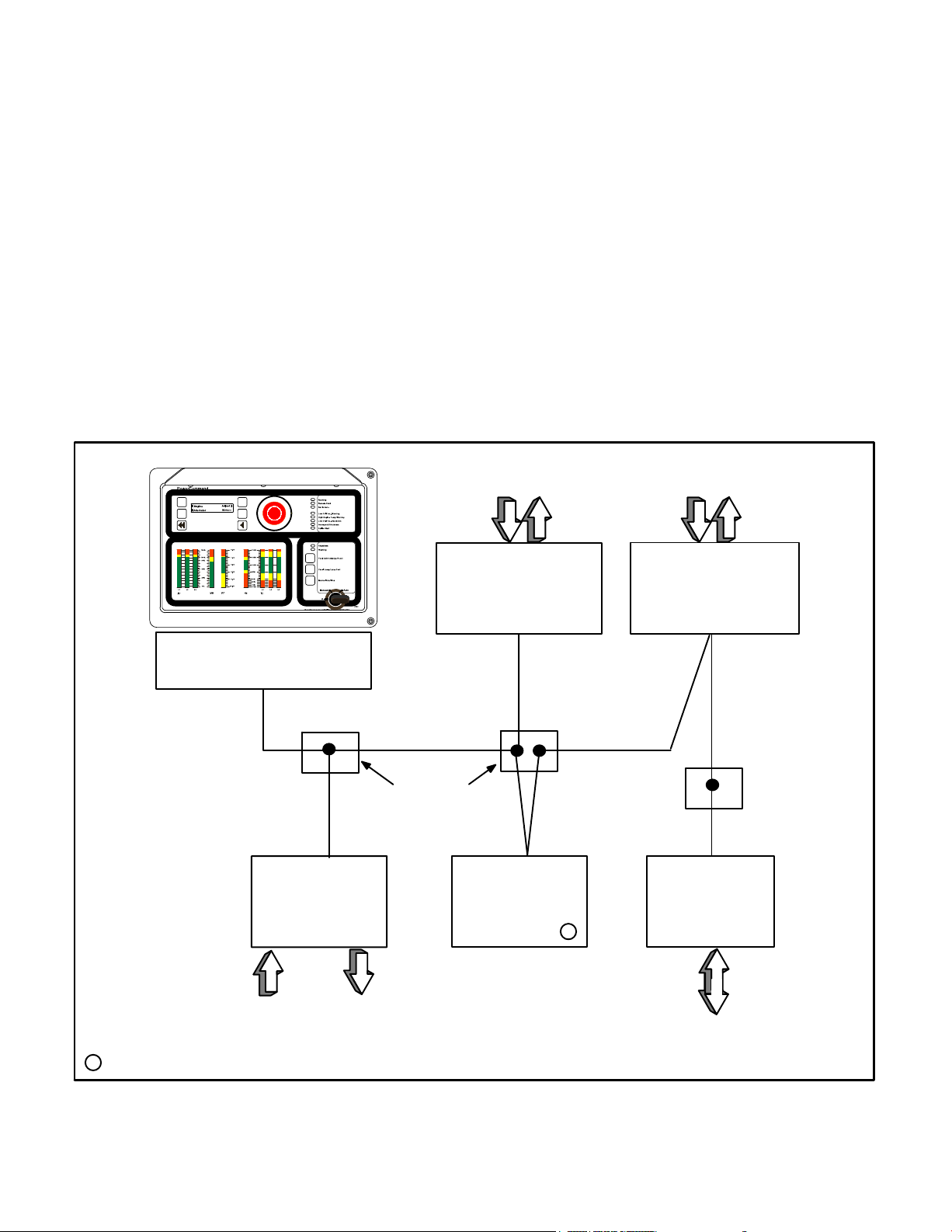
SYSTEM OVERVIEW
Figure 1-1 shows a block diagram using some of the
network modules described in this manual. The network and network modules are covered in detail in
the following sections.
The PowerCommand Control (PCC) communi-
cates through the Genset Communications Module
with other modules, such as a Digital I/O Module, or
Network Communications Module.
The Genset Communications Module (GCM) is
mounted in the PCC 3100 and is required for connecting the PCC to the network.
The Genset L
the PCC 3200 and is required for connecting the
PCC to the network.
ONWORKS Card (GLC) is mounted in
The Genset Network Communications Module
(NCM) is mounted in the PCC 2100 and is required
for connecting the PCC to the network.
The ATS Network Communications Module
(NCM) is mounted in the PowerCommand automatic transfer switch (OTPC, BTPC, OHPC, or CHPC)
and is required for connecting the transfer switch to
the network.
The Digital I/O Module (DIM) provides a group of
relay contact outputs and discrete inputs for interfacing the PowerCommand system to alarm or status outputs and to equipment that does not have
compatible communications capability.
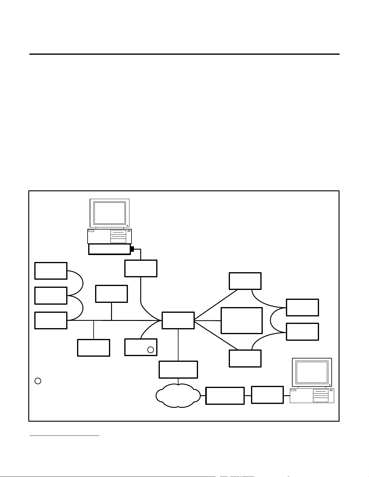
PCC 2100 NETWORK
COMMUNICATIONS MODULE
(NCM)
DIGITAL I/O
MODULE (DIM)
NON-OTPC/BTPC
TRANSFER SWITCH
CONTROLS
COMMUNICATIONS
POWERCOMMAND
FT-10 NETWORK
JUNCTION
BOX
ANNUNCIATOR
MODULE
(CCM-T)
LONWORKS
SYSTEM
(LSA)
NON-PCC
GENERATOR SET
CONTROLS
COMMUNICATIONS
MODULE
(CCM-G)
JUNCTION
BOX
SLTA-10
T
CUSTOMER
= NETWORK TERMINATOR
T
RELAY
INPUTS
OUTPUTS
FIGURE 1-1. BLOCK DIAGRAM OF NETWORK MODULES
1-3
MODEM OR
LOCAL PC
Copyright 2017 Cummins Inc.
Page 18
The LONWORKSR System Annunciator (LSA) al-
1
1
lows remote annunciation via the PowerCommand
Network of a genset or transfer switch etc. The annunciator shows an operator what is happening in
the network.
FT-10 NETWORK
CHANNEL
The SLTA-10 Gateway provides a network inter-
face to a PC or modem.
The Junction Box/Terminator provides connec-
tion points for network power and data wires.
The Controls Communications Module (CCM)
allows interfacing the network to a non−PCC generator set (CCM-G) or transfer switch (CCM-T).
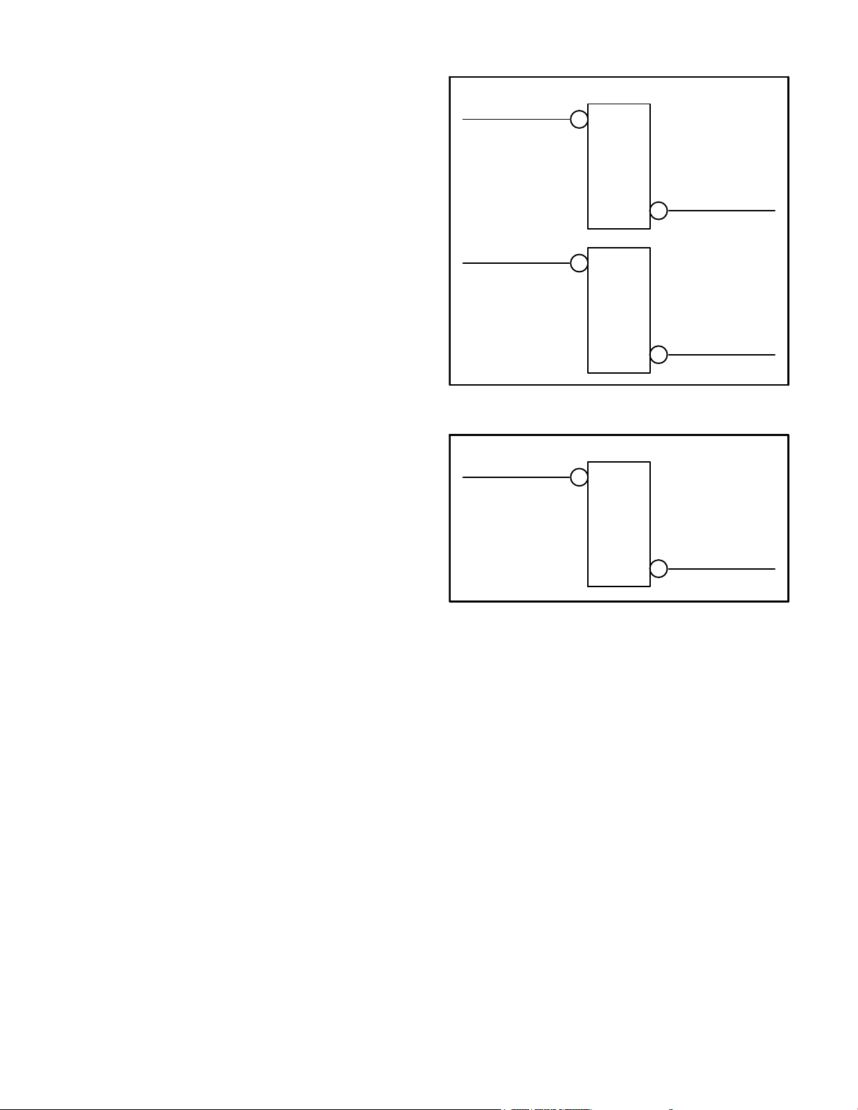
The PowerCommand L
ONWORKS Network Router
connects two communications channels (for example, FT-10 to FT-10) and routes messages between
them (see Figure 1-2).
The PowerCommand Etherlon Router connects
one FT-10 Network LonWorks channel to one
Ethernet channel (see Figure 1-3).
ROUTER
NETWORK
FT-10 NETWORK
CHANNEL
ROUTER
NETWORK
FIGURE 1-2. NETWORK ROUTERS
FT-10 NETWORK
CHANNEL
ROUTER
EITHERLON
FT-10 NETWORK
CHANNEL
TP-78 NETWORK
CHANNEL
EITHERNET
CHANNEL
FIGURE 1-3. ETHERLON ROUTER
Copyright 2017 Cummins Inc.
1-4
Page 19
2. Network Hardware and Wiring
OVERVIEW
This section describes the free topology (FT) network communications protocol and the individual
R
modules used in the PowerCommand
FT-10 network. This section also describes network media,
network power supply, and physical connection requirements. For a definition of the terms used in a
PowerCommand network, refer to the Glossary in
Appendix A.
NETWORK CONFIGURATION
The PowerCommand network uses a free topology
(Figure 2-1). The network is made up of individual
devices that are connected by stranded twisted-pair
MODEM
communications cable for the transmission of network data. Network power is transmitted over wires
in the DC conduit.
The devices used in this network include a free topology transceiver (FTT-10). FTT-10 devices are
transformer isolated, have a 78 kbps bit rate, and
are polarity insensitive. External power must be
provided for FTT-10 devices (LSA, DIM, CCM-T,
CCM-G, GLC, NCM, and GCM).
A router can be configured as a repeater to extend a
segment into a channel. Repeaters transmit every
network variable signal they receive, no matter
where it originates.
POWERCOMMAND NETWORK
22 AWG MAXIMUM LENGTH
1640 FEET (500 M) PER SEGMENT
NOTE: Although 128 devices can be added to a
channel, only 64 devices are allowed per segment.
Add a repeater between segments to extend the
reach and allow for a higher device count.
CCM-G
CCM-G
CCM-G
T
= Network Terminator
GLC
CCM-T
SLTA-10
Channel 1
PCC 2100
NCM
T
NOTE: One device on each
segment must be terminated.
* Do not use the JBT terminator in FT-10 networks.
FIGURE 2-1. FREE TOPOLOGY NETWORK EXAMPLE
PowerCommand is a registered trademark of Cummins Inc.
Echelon, LonW
ORKS, AND Neuron are registered trademarks of Echelon Corporation.
JBT*
ETHERLON
ETHERNET
CCM-T
OTPC/BTPC/
OHPC/CHPC
ATS NCM
ETHERLON
DIM
LSA
GCM
SLTA-10
2-1
Copyright 2017 Cummins Inc.
Page 20
A free topology architecture allows for wiring the
control devices without topology restrictions. It supports the use of star, loop, and/or bus wiring. Some
of the advantages of free topology include:
It allows for a method of wiring that best suits
the installation, thus reducing the need for advanced planning. It also allows for last minute
changes.
PowerCommand Network
(twisted pair)
Rewiring of existing installations is usually not
required.
The network can be expanded by tapping into
the existing wiring where it is most convenient
to do so.
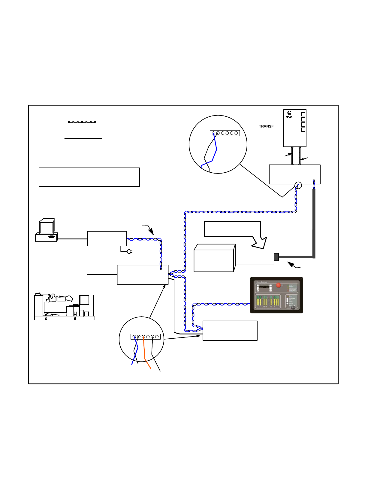
Figure 2-2 shows a typical network with several
modules. Refer to Figure E-1 in Appendix D for a
more detailed network example.
Data
on pins
+
+
1 & 2
−−
TRANSFER
SWITCH
Non-PowerCommand Network
NOTE: JBTs can be used as twisted pair or
power connection points only. Do not use
the JBT terminator for FT-10 networks.
Customer’s PC
COM1
Connect one
Power Wiring
(RS−232C)
SLTA-10 Cable
Network Patch Cable
FT-10 SLTA-10
Gateway Module
Site Gateway
Control Wiring
PowerCommand
CCM-G
(Terminated)
Blue
Network Data and Power Connector:
6-pin Black connector
Blue − White/Blue
For Installation
and Service only
Blue − White/BlueBlue − White/Blue
RJ45
Jack
Technician’s
Laptop PC
Echelon PCC-10
PowerCommand
Control 2100
Connect to NCM Terminal Block
PCMCIA card
AC WIRING
PowerCommand
Controls Communications
Module - ATS
DC WIRING
RJ45
Jack
Echelon FT-10 Cable
Copyright 2017 Cummins Inc.
Data
on pins
1 & 2
+
+
−−
PowerCommand
LonWorks System Annunciator
Blue
B+
Ground
FIGURE 2-2. TYPICAL NETWORK CONFIGURATION
2-2
Page 21

SYSTEM DESCRIPTION
The PowerCommand Network is a distributed control network. Echelon
vides the communications protocol via Echelon’s
Neuron
Chip and firmware. The network consists
of nodes (for example: PCCs with Genset Communications Modules, Digital I/O Modules, Controls
Communication Modules, and Network Gateway
Modules) wired together on a common network
data bus.
The control of the system does not reside in a central device, but rather is distributed at the system
component level. That is, each node has its own intelligenceintelligence needed at that location to
perform functions for that particular component.
The nodes communicate control and monitoring information to one another over the network data bus.
LonWorks technology pro-
The application is defined by naming the network
variable inputs and outputs for each device.
Nodes that do not have a local source of uninterrupted power are supplied by the network power
lines. These power lines must be in the DC power
conduit.
Neuron Chip
Each node contains a Neuron Chip. The primary
function of the Neuron Chip is to serve as a communications link between the system component located at that node and other system components on
the network. The Neuron Chip also provides the
node with some local processing power to read
switch positions, drive outputs, read analog data,
etc. The Neuron Chip communicates by directly
transmitting and receiving through a transformercoupled transceiver.
The nodes, their connections to one another, and
the modules/devices they control/monitor collectively form the distributed control system. A distributed control system is a more robust control
scheme than a conventional central control system.
Single points of failure in the distributed control system do not necessarily render the whole system inoperative.
Communications Protocol
A distributed control network operates on a peer-topeer communication protocol, whereby any device
on the communication channel can communicate
with any other device at any time.
Messages can be prioritized so that critical control
messages have first access to the network. Reliability of transmission is provided through use of acknowledged or repeated message service levels.
Accuracy of the message is checked by cyclical redundancy checking.
POWERCOMMAND CONTROLS
The PowerCommand Controls (PCCs) are a family
of microprocessor-based controls for Cummins Inc.
generator sets. They provide fuel control and engine speed governing, main alternator voltage output regulation, and complete generator set control
and monitoring.
The operating software provides control of the generator set and its performance characteristics, and
displays operating information on a digital and analog display panel.
The PCC communicates through the Genset Communications Module or Network Communications
Module with other modules, such as a L
System Annunciator or Network Gateway Module.
Variations of the PowerCommand Controls are covered in your generator set Installation, Operator’s,
and Service manuals.
ONWORKS
2-3
Copyright 2017 Cummins Inc.
Page 22

SYSTEM MODULES
Genset Communications Module (GCM)
The Genset Communications Module (GCM) is
mounted inside the PCC 3100, and is required for
connection of the PCC 3100 to the network.
The GCM provides an interface for data between
the PCC 3100 and other modules on the network. It
communicates with the PCC 3100 base board
through the PCC’s serial port to determine the operating state of the control. For example, the GCM
monitors PCC 3100 data such as voltage, current,
engine speed, and oil temp; and then stores it for the
network.
The GCM also provides some direct local control
and monitoring of the PCC 3100. Outputs from the
GCM allow it to “wake up” the PCC 3100 when
needed, or to cause an emergency shutdown on
command. It monitors Not-In-Auto mode and battery voltage (when the PCC is asleep).
The GCM is installed piggyback on the analog
board within the PCC 3100. A description of the
GCM for PCC 3100 controls is covered in Section 7.
Genset LonWorks Card (GLC)
ules on the network. It communicates with the PCC
base board through the PCC’s serial port to determine the operating state of the control. For example, the NCM monitors PCC data such as voltage,
current, engine speed, and oil temp; and then
stores it for the network.
The NCM is installed piggyback on the base circuit
board within the PCC 2100. A description of the
NCM for PCC 2100 controls is covered in Section
10.
Network Communications Module (NCM) −
PowerCommand ATS
The PowerCommand ATS Network Communications Module (NCM) is mounted inside the OTPC/
BTPC/OHPC/CHPC ATS, and is required for connection of the ATS to the network.
The NCM provides an interface for data from the
transfer switch to other modules on the network. It
communicates with the digital board providing complete monitoring and control of the transfer switch.
The NCM is installed piggyback on the digital module within the ATS. A description of the NCM for
PowerCommand Automatic Transfer Switches is
covered in Section 11.
The Genset LONWORKS Card (GLC) is mounted in-
side the PCC 3200, and is required for connection
of the PCC 3200 to the network.
The GLC provides an interface for data between the
PCC 3200 and other modules on the network. It
communicates with the PCC 3200 base board to
determine the operating state of the control. For example, the GLC monitors PCC data such as voltage, current, engine speed, and oil temp; and then
stores it for the network.
The GLC is installed in slot 4 in the control box card
cage assembly. A description of the GLC for PCC
3200 controls is covered in Section 9.
Genset Network Communications Module
(NCM) − PCC 2100 Control
The Genset Network Communications Module
(NCM) is mounted inside the PCC 2100, and is required for connection of the PCC to the network.
The NCM provides an interface for data between
the PowerCommand 2100 Control and other mod-
Digital I/O Module (DIM)
The base and expansion DIMs provide a group of
relay contact outputs and discrete inputs for interfacing the PowerCommand System to status outputs and to equipment that does not have compatible communications capability.
Each module (base and expansion) provide eight
0.5A, 250VAC/30VDC Form-C dry contact relay
outputs, which are driven by data from the network.
The contacts are connected to pluggable terminal
blocks for field wiring. Each relay can be programmed to operate from any SNVT switch variable
on the network. Each module also includes four digital inputs to couple user inputs to the network for
use elsewhere in control or monitoring.
Description and installation of the Digital I/O Module
is covered in Section 12.
SLTA-10 Gateway
The PowerCommand LONWORKS SLTA-10 Gateway provides a network interface to a PC either directly or through a modem. It translates network
Copyright 2017 Cummins Inc.
2-4
Page 23

protocol into a protocol that can be understood by a
PC.
PCC generator sets, transfer switches, system or
breakers.
The SLTA-10 Gateway connects to network data
wire through a 2-position connector. The SLTA-10
Gateway receives its power from AC wall power,
and should be backed up by a standby uninterruptable power supply (UPS).
The SLTA-10 Gateway allows software running on a
PC to access, and control all modules on a network.
The PowerCommand Software uses this module to
access the network.
A description of the SLTA-10 Gateway is covered in
Section 13.
Junction Box/Terminator
A Junction Box/Terminator (JBT) provides connection points for network power and data wire. Junction Boxes may be used throughout a network for
connecting in Pass Thru, Local Loop and Stub configurations. Stub connections are used in a multidrop bus topology. The JBT is a potted assembly.
A junction box provides two 6-position pluggable
connector for data and power, two RJ45 jacks for
24AWG stub connections, a switch to connect the
data lines to a terminator circuit*, and a switch to select either a Pass Thru or a Local Loop connection
between the data lines on the two connectors.
These modules monitor discrete inputs, AC and DC
analog inputs, and communicate data to the PowerCommand Network.
The CCM has 16 channels of analog input and 32
digital inputs.
The module also includes eight Form-C output relays to provide control of the monitored equipment
from the network. For example, these outputs can
be used to initiate a test within a transfer switch, or
to remotely start a generator set.
A description of the CCM for genset applications is
covered in Section 16, and a description of transfer
switch applications is covered in Section 17.
Network Router
The Network Router (RTR) connects two communications channels by passing messages between
the two channels. The PowerCommand Network
Router is configured to connect two stranded twisted
pair/transformer isolated 78kb (FT-10) channels.
* The terminator circuit must only be used in a TP-78
network.
Description of the JBT is covered in Section 14.
LONWORKS System Annunciator (LSA)
The LONWORKSR System Annunciator (LSA) is connected to the network by stranded twisted pair communication wire.
The LSA has 20 LEDs to annunciate alarms. This
module has its own Operator’s Manual (900-0293).
The LSA is covered in Section 15 of this manual.
Controls Communications Module
for Generator Set and Transfer Switch
Monitoring
The Controls Communications Module (CCM) allows interfacing the network to conventional non-
The Router can be used within a PowerCommand
Network to extend the physical length of the network beyond 1640 feet (500 m) and/or increase the
maximum number of nodes to more than 64 nodes.
Refer to the Section 18 for application information
on the Network Router.
Etherlon Router
The PowerCommand Etherlon Router(s) connects
one FT-10 Network L
Ethernet channel.
One Etherlon Router must be used to go from an
FT-10 network to an Ethernet channel and another
must be used to go from the Ethernet channel back
to the FT-10 network.
Refer to the Section 19 for application information
on the Etherlon Router.
ONWORKSR channel to an
2-5
Copyright 2017 Cummins Inc.
Page 24

ModLon II Gateway
The Modlon II Gateway will be obsoleted in October
2016 and replaced with the PowerCommand Lon
Gateway (A054V134). The PowerCommand Lon
Gateway is currently available for purchase and will
supersede any orders for the Modlon II Gateway after it has been obsoleted. Software and LonMaker
stencils for the PowerCommand Lon Gateway are
available on InCal for download.
The ModLon II Gateway provides a direct Echelon
LonWorks network interface to any device that can
communicate ModBus RTU or ModBus ASCII. This
module translates LonWorks network protocol into
ModLon ASCII or RTU.
A description of the ModLon II Gateway is included
in Section 20.
Copyright 2017 Cummins Inc.
2-6
Page 25

DATA TRANSMISSION MEDIA
The modules communicate at 78 kbps over a communications channel of 22 AWG UL Level IV (or EIA
Category 5) stranded twisted pair communications
wire. The network data signal is coupled to the
stranded twisted pair wire by transformer-coupled
transceivers in each node. Nodes are isolated by
transformer from the data lines, which makes the
data wiring polarity insensitive. A high degree of
noise immunity is achieved with this medium.
Wiring and connection of data transmission media
is covered in the individual module sections.
NETWORK TOPOLOGY
There are two types of wiring topologies:
Free Topology (Preferred − see Table 2-1)
− Maximum Length Per Segment = 500 me-
ters (1640 feet)
TABLE 2-1. NETWORK DATA SPECIFICATION
− Maximum Number of Segments Per
Channel = 2
− Maximum Number of Devices per Segment = 64
− Termination − One termination is required
on an FT-10 network segment. Proper termination of the network is important for
reliable communications. All PGA nodes
have the terminator circuit built in except
the Gateway and Routers. Termination is
activated by a slide switch. Network terminator 300−5669 can also be used.
Multidrop Bus (Daisy Chain)
− Maximum Length = 2700 meters (8858
feet)
− Maximum Number of Devices = 44
− Termination − Two multidrop bus termina-
tors (not the terminators on the devices)
are required, one at each end of the network (Onan P/N 300−5729).
Data Communications Type: Transformer coupled, Differential Manchester encoding
Media: Stranded twisted pair communications wire
Bit Rate: 78k bits/sec
Wiring Topology: Free Topology
Polarity: Polarity insensitive
Max Segment Length: 1640 feet (500 meters)
Termination: One terminator required (recommended that the terminator be located
near the center of the segment)
Minimum Wire Type Required: Segment − Unshielded 22 AWG UL Level IV or EIA Cat. 5
Stranded Twisted Pair Communication Wire
Maximum Length of Exposed
Untwisted Wire at a Connector: 1/2 Inch (13 mm)
Maximum Number of Nodes: 128 per channel, 64 per segment
Maximum no. of channels: 20
Wire Color Codes: Blue and White/Blue − primary wire pair for data
Orange and White/Orange − secondary wire pair for Local Loops with
2 pair cable
Connector: PGA nodes − 6 position pluggable black screw terminal block
PGA Junction Box/Terminator − pluggable screw terminal blocks
and RJ45s
NGM node — 2-position connector (orange screw terminal block)
2-7
Copyright 2017 Cummins Inc.
Page 26
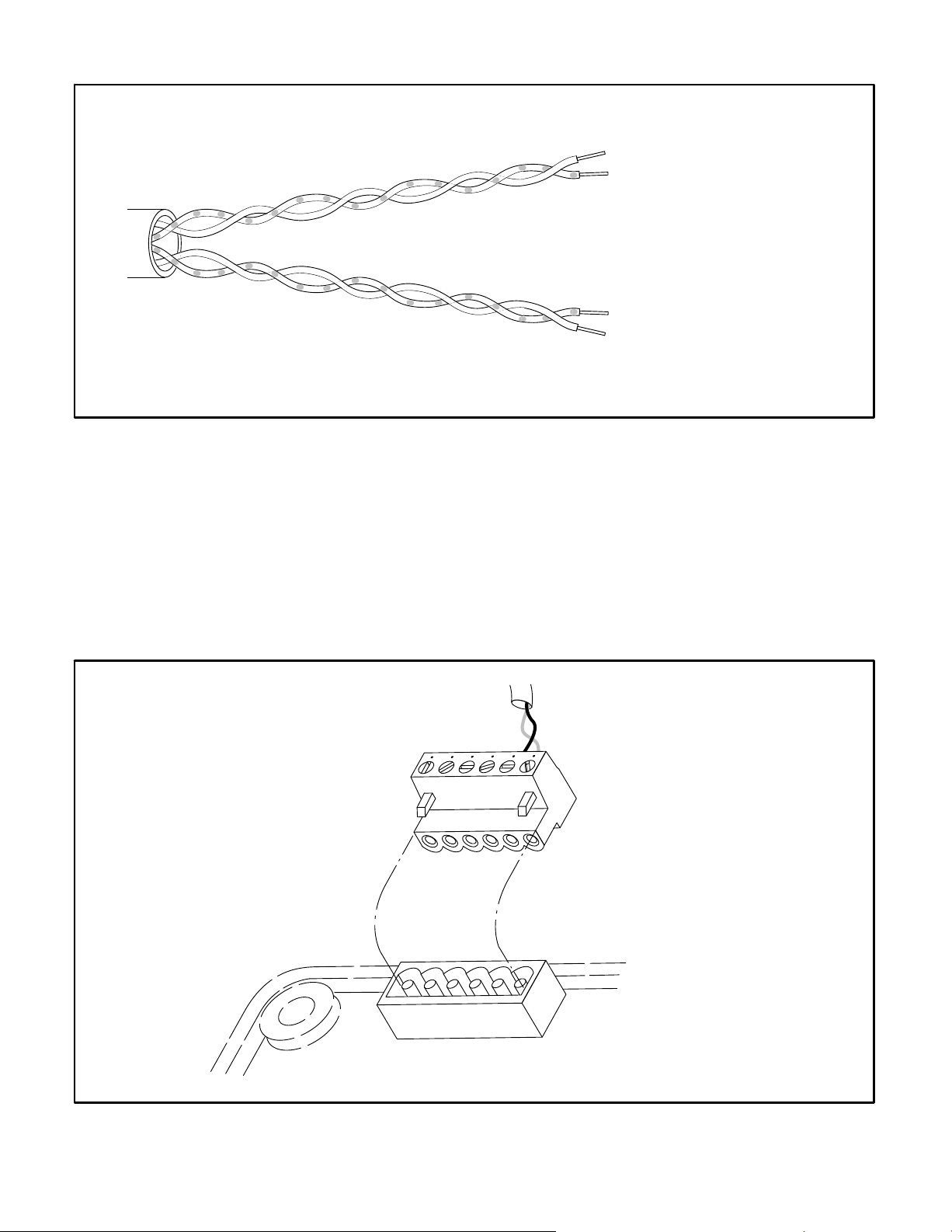
BLUE
PRIMARY DATA WIRES
WHITE/BLUE
WHITE/ORANGE
SECONDARY DATA WIRES
FOR LOCAL LOOP
DO NOT USE FOR DC POWER
ORANGE
FIGURE 2-3. TWO STRANDED TWISTED PAIR COMMUNICATIONS WIRE
CONNECTORS AND WIRE COLOR CODES
The CCM-G, CCM-T, LSA, GLC, and the base DIM
have a black, 6-position pluggable screw terminal
block for connection to network data and network
power (see Figure 2-4). These devices also have
one RJ45 connector (see Figure 2-5).
The Junction Box/Terminator module has two
6-position pluggable terminal blocks (see Figure
2-4), as well as two RJ45 connectors.
The OTPC/BTPC/OHPC/CHPC ATS NCM uses a
network harness to connect from the module’s
2-position connector (see Figure 2-6) to two positions on the DIN rail customer connection terminals.
This device also has an RJ45 connector.
CONNECTOR
Copyright 2017 Cummins Inc.
6 5 4 3 2 1
TERMINAL BLOCK
FIGURE 2-4. 6-POSITION PLUGGABLE CONNECTOR
2-8
Page 27
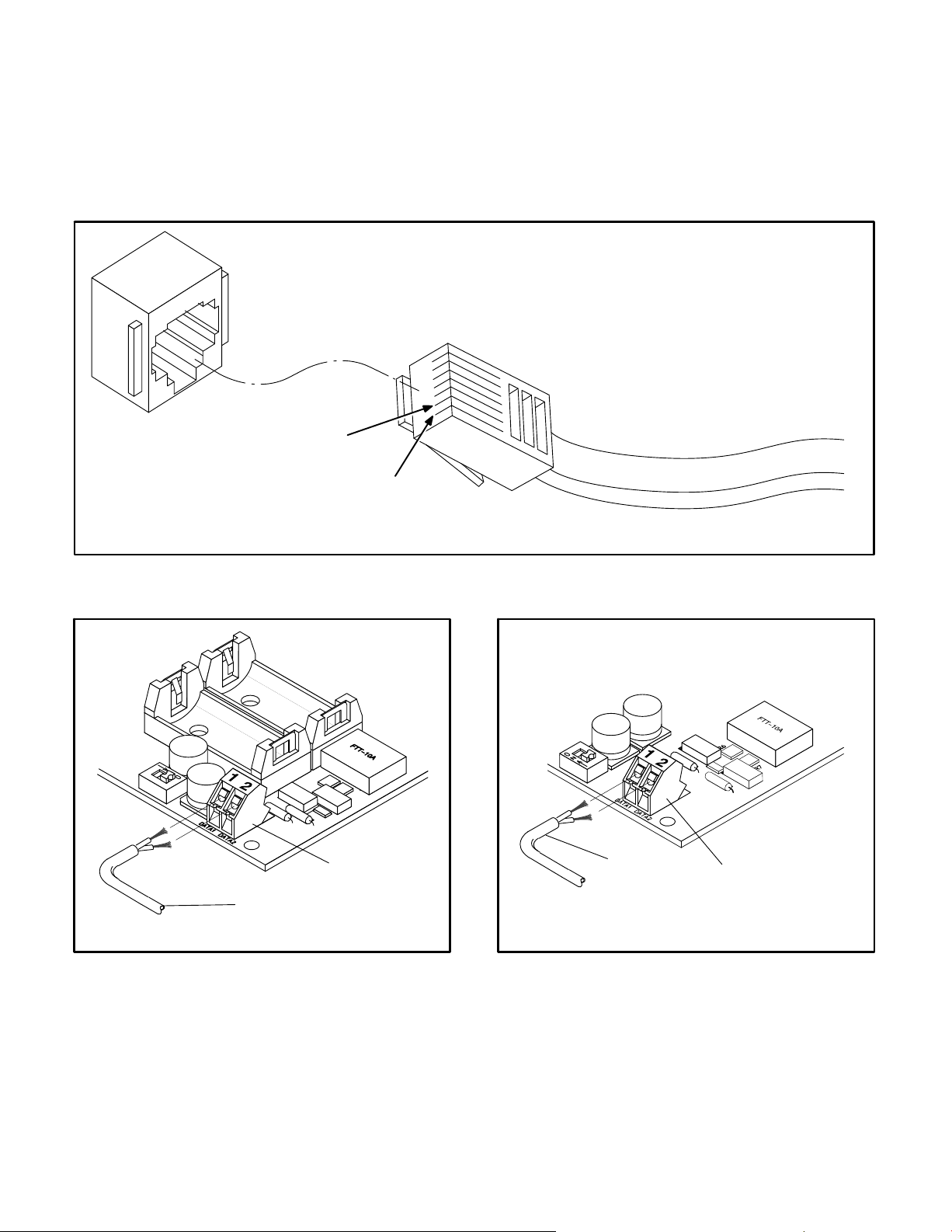
The PCC 2100 Genset NCM uses a network harness to connect from the module’s 2-position connector (see Figure 2-7) to another network device.
This device also has an RJ45 connector.
The SLTA-10 Gateway has a 2-position connector
RJ45 CONNECTOR
POSITION 2
POSITION 1
(see Figure 2-8) for network data connections and
network termination.
Connector positions and wire color codes are listed
in Tables 2-2 and 2-3.
FIGURE 2-5. RJ45 CONNECTOR
CONNECTOR
NETWORK
HARNESS
FIGURE 2-6. OTPC/BTPC/OHPC/CHPC ATS
NCM
TWO-POSITION CONNECTOR (OLD
PRODUCTION)
NETWORK
HARNESS
FIGURE 2-7. PCC 2100 AND
OTPC/BTPC/OHPC/CHPC
GENSET
NCM TWO-POSITION CONNECTOR
CONNECTOR
(NEW PRODUCTION)
2-9
Copyright 2017 Cummins Inc.
Page 28
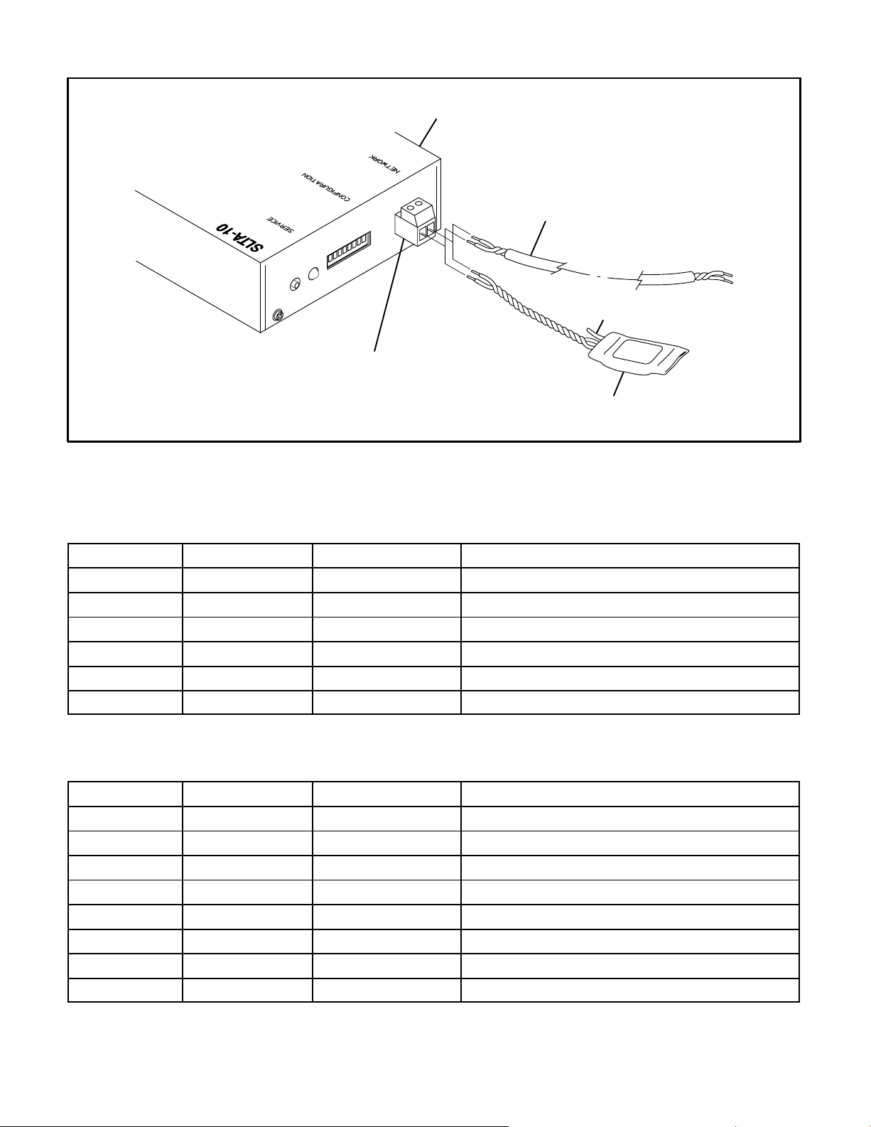
LONWORKS
GATEWAY
NETWORK
STRANDED
TWISTED PAIR
NETWORK
CONNECTOR
FIGURE 2-8. NETWORK CONNECTION
CLIPPED
GROUND LEAD
NETWORK
TERMINATOR
TABLE 2-2. 6-POSITION PLUGGABLE TERMINAL BLOCK
Position Signal Wire Color Code Comments
1 Net Data1 white/blue if 2pr cable − white/orange for Local Loop
2 Net Data2 blue if 2pr cable − orange for Local Loop
3 Net Power+
4 Net Power+
5 Net Power−
6 Net Power−
TABLE 2-3. RJ45 CONNECTOR
Position Signal Wire Color Code Comments
1 Net Data1 white/blue 24AWG only
2 Net Data2 blue 24AWG only
3 not used
4 not used
5 not used
6 not used
7 not used
8 not used
Note: Position numbering goes from left to right when looking into the jack with the pins at the top and the
latching notch at the bottom.
Copyright 2017 Cummins Inc.
2-10
Page 29

WIRING GUIDELINES
Communication over stranded unshielded twisted
pair (UTP) could be distorted by external sources of
electromagnetic interference (EMI), especially if the
conductors are physically degraded in any way. To
avoid or minimize this interference, observe the following guidelines.*
CAUTION
can cause communication signal distortion,
which can cause network failure and unintended equipment operation. Read and follow
these wiring guidelines.
Observe all local wiring codes. Refer to the NEC
(NFPA70) section on Wiring Methods and Materials
for general wiring methods and procedures.
Routing: Whenever possible, cabling should be
installed over corridor areas or along lines that are
parallel to the contours of buildings. All deviations
from straight runs should be made at right angles.
Keep wire away from sharp, abrasive, and hot surfaces.
Separation from sources of EMI: All cabling
should be installed in such a way as to comply with
the minimum separations from AC power sources,
as listed in Table 2-4.
In general, communications wiring should not be located in spaces that are shared with electrical panels, transformers, or other high voltage equipment.
Electromagnetic interference (EMI)
Tension: All cabling should be free from tension at
both ends, as well as over the length of each run.
Stranded Twisted pairs: All terminations should
be made in such a way as to minimize the extent to
which each stranded twisted pair is unraveled
at the point of its physical termination. Allow no
more than 0.5 inch (13 mm) of exposed untwisted
pairs.
UTP cable bends: UTP cable bends, or radii,
should be no less than eight times the cable diameter.
Harsh, hazardous, or corrosive environments:
Communications wiring should not be installed
where vapors, fumes, corrosives, dusts, or other industrial byproducts are present without taking appropriate precautions to protect the cables. Installers and cabling manufacturers of the materials involved must be consulted in all such cases.
Grounding and bonding: Although the use of UTP
does not involve the use of shielded cables in horizontal station runs, the use of shielding in high-paircount UTP riser cables as well as cables of all types
used in outdoor conditions is not uncommon. In
some cases, qualified installers or manufacturers
will make related recommendations in the interest
of human safety or mechanical protection of
installed cables (e.g., shielding against rodents).
When shielded cables are used, all applicable regulations for grounding and bonding as defined by local building codes for electrical materials must be
strictly adhered to.
TABLE 2-4. MINIMUM SEPARATION DISTANCES OF UTP FROM SOURCES OF EMI
Condition <2 kVA 2−5 kVA >5 kVA
Unshielded power lines or electrical equipment in proximity
to open or nonmetal pathways
Unshielded power lines or electrical equipment in proximity
to a grounded metal pathway
Power lines enclosed in a grounded metal conduit (or equivalent shielding) in proximity to a grounded metal pathway
*These guidelines are derived from “The Do’s and Don’ts of UTP Cabling,” by Mark W. McElroy, in EC&M, June 1994.
2-11
5 in.
(127 mm)
2.5 in.
(64 mm)
12 in.
(305 mm)
6 in.
(152 mm)
3 in.
(76 mm)
Copyright 2017 Cummins Inc.
24 in.
(610 mm)
12 in.
(305 mm)
6 in.
(152 mm)
Page 30

NETWORK POWER
This section describes the methods of supplying
power (referred to as network power) to those network modules that require an external power
source. Observe all local wiring codes and regulations when designing and installing network power
wiring.
The modules that require DC network power are:
Locate the CCM as close to the device being monitored as possible. Do not mount the CCM on a genset or vibration damage can result.
If current transformers will be monitored, the distance limitations between the current transformers
and the CCM will generally be more restrictive than
the network power distance limitations. Refer to the
appropriate CCM section for current transformer
distance charts.
Base Digital I/O Module (DIM)
L
ONWORKS System Annunciator (LSA)
Controls Communications Module − Genset
Applications (CCM-G)
Controls Communications Module − Automatic
Transfer Switch Applications (CCM-T)
OTPC/BTPC/OHPC/CHPC ATS Network
Communications Module (NCM)
The base DIM, LSA, and CCM-G modules can be
powered by a 24V genset battery. The 24V genset
battery can supply one or more of these modules
within specific distance limitations.
The genset batteries cannot deliver network power
over a long distance due to the voltage drop during
cranking. The genset batteries require a battery
charger that can supply the network load and maintain the batteries. Refer to the genset manual to determine B+ and GND connection points.
The CCM-G module can also be powered by a 12V
genset battery power supply. The distance is very
limited and no other types of modules can be powered off the same network power circuit. Refer to
Table 2-6 for distance and wire gauge requirements. (When powering CCM modules only from a
24V genset battery, refer to Table 2-7.)
The CCM-T network power will be supplied by a 12
VDC battery that is included along with a battery
charger in the CCM-T kit.
A 12V genset battery will not provide an adequate
power supply for DIMs and LSAs. In cases where
the genset is powered by a 12V battery, a separate
power supply must be used.
The OTPC/BTPC/OHPC/CHPC ATS NCM is powered by two 2V Lithium batteries.
SELECTING NETWORK POWER
CONFIGURATION AND WIRE SIZE
This section describes the procedures for selecting
the copper wire gauge needed to supply network
power. The wire gauge selected will be a function of
the type and number of modules used, the type of
power supply selected, and the distance between
the power source and the farthest module in the
power supply circuit. Do not use stranded twisted
pair data wire for DC power.
Use this procedure for developing network power
circuits for DIM, LSA, and CCM-G modules only.
(CCM-T modules are not included because they are
equipped with their own power supply.)
Refer to Figure 2-9 for illustrations of typical circuit
configurations and notes.
1. Determine the number and type of load modules (DIM, LSA, and CCM-G modules).
2. Calculate the Total Load Factor by adding up
the individual load factors for each DIM, LSA,
and CCM-G in each circuit.
Each CCM-G has a load factor of: 2.40
Each DIM has a load factor of: 0.10
Each LSA has a load factor of: 0.10
3. Determine the distance between the power
source and the farthest load device (DIM, LSA
or CCM-G module) in the circuit.
4. Look up the required minimum copper wire
gauge. Refer to Table 2-5 for 24V genset battery power supply.
Copyright 2017 Cummins Inc.
2-12
Page 31

Example:
Application: The network plans call for one CCMG at 40 feet (12 m), one DIM at 50 feet (15.2 m) and
one LSA at 300 feet (91.4 m). The farthest module
from the network power source is the LSA. The top
drawing in Figure 2-9 shows each of these modules
being supplied in one circuit.
24VDC SUPPLY POWERING
ONE NETWORK POWER CIRCUIT
Calculation: The total load factor =
(1 X 2.40) + (1 X 0.10) + (1 X 0.10) = 2.60
Wire Size Required: Look up the total load factor
(2.60) in the first column of Table 2-5. Then look
across the table to find a distance equal to or greater
than the distance to the farthest load device (300
feet). Table 2-5 indicates that the maximum distance obtainable is only 274 feet, this power supply
is not adequate to supply all of these modules in one
circuit.
The circuit can be redesigned so the CCM-G module is supplied by a second circuit off the same
source (center diagram in Figure 2-9). Be careful
not to exceed the current rating of the circuit. (The
load factor equals the maximum current draw.)
−OR−
The circuit can be supplied by more than one genset power supply if available (bottom diagram in
Figure 2-9). Do not connect separate network power sources in parallel or damage to the batteries will
result from overcharging.
CCM-G
DIM
LSA
24VDC SUPPLY POWERING
TWO NETWORK POWER CIRCUITS
40 FEET
(12 M)
CCM-G
DIM
LSA
300 FEET
(91.4 M)
300 FEET
(91.4 M)
Using either of the redesigned circuits, recalculate
the wire gauge based on steps 1 thru 4. The CCM-G
with a load factor of 2.40 can be supplied using 18
gauge wire. The DIM and LSA with a total load factor of 0.20 can be supplied using 18 gauge wire.
TWO 24VDC SUPPLIES POWERING
ONE NETWORK POWER CIRCUIT EACH
40 FEET
(12 M)
CCM-G
LSA
DIM
FIGURE 2-9. NETWORK POWER DIAGRAMS
300 FEET
(91.4 M)
2-13
Copyright 2017 Cummins Inc.
Page 32

TABLE 2-5. 24V GENSET BATTERY POWER SUPPLY
LOAD
WIRE
AWG
TOTAL
LOAD
FACTOR
18
(0.50 mm
2
)
MAXIMUM DISTANCE BETWEEN THE NETWORK POWER SOURCE
AND THE FARTHEST LOAD DEVICE IN FEET OR METERS
FEET METERS FEET METERS FEET METERS FEET METERS
16
(0.50 mm
2
)
(0.75 mm
2
)
14
(1.25
12
mm
0.10 1887 575.1 2995 912.9 4754 1449.1 7547 2300.3
0.20 943 287.5 1498 456.4 2377 724.6 3774 1150.2
0.30 629 191.7 998 304.3 1585 483.0 2516 766.8
0.40 472 143.8 749 228.2 1189 362.3 1887 575.1
0.50 377 115.0 599 182.6 951 289.8 1509 460.1
0.75 252 76.7 399 121.7 634 193.2 1006 306.7
1.00 189 57.5 300 91.3 475 144.9 755 230.0
1.25 151 46.0 240 73.0 380 115.9 604 184.0
1.50 126 38.3 200 60.9 317 96.6 503 153.4
1.75 108 32.9 171 52.2 272 82.8 431 131.4
2.00 94 28.8 150 45.6 238 72.5 377 115.0
2.25 84 25.6 133 40.6 211 64.4 335 102.2
2.50 75 23.0 120 36.5 190 58.0 302 92.0
2.75 69 20.9 109 33.2 173 52.7 274 83.6
3.00 63 19.2 100 30.4 158 48.3 252 76.7
3.25 58 17.7 92 28.1 146 44.6 232 70.8
3.50 54 16.4 86 26.1 136 41.4 216 65.7
3.75 50 15.3 80 24.3 127 38.6 201 61.3
4.00 47 14.4 75 22.8 119 36.2 189 57.5
4.25 44 13.5 70 21.5 112 34.1 178 54.1
4.50 42 12.8 67 20.3 106 32.2 168 51.1
4.75 40 12.1 63 19.2 100 30.5 159 48.4
5.00 38 11.5 60 18.3 95 29.0 151 46.0
5.25 36 11.0 57 17.4 91 27.6 144 43.8
5.50 34 10.5 54 16.6 86 26.3 137 41.8
5.75 33 10.0 52 15.9 83 25.2 131 40.0
6.00 31 9.6 50 15.2 79 24.2 126 38.3
6.25 30 9.2 48 14.6 76 23.2 121 36.8
6.50 29 8.8 46 14.0 73 22.3 116 35.4
6.75 28 8.5 44 13.5 70 21.5 112 34.1
7.00 27 8.2 43 13.0 68 20.7 108 32.9
7.25 26 7.9 41 12.6 66 20.0 104 31.7
7.50 25 7.7 40 12.2 63 19.3 101 30.7
2
)
Copyright 2017 Cummins Inc.
2-14
Page 33

TABLE 2-5. 24V GENSET BATTERY POWER SUPPLY (Continued)
LOAD
WIRE
AWG
TOTAL
LOAD
FACTOR
18
(0.50 mm
2
)
MAXIMUM DISTANCE BETWEEN THE NETWORK POWER SOURCE
AND THE FARTHEST LOAD DEVICE IN FEET OR METERS
FEET METERS FEET METERS FEET METERS FEET METERS
16
(0.50 mm
2
)
(0.75 mm
2
)
14
12
(1.25 mm
7.75 24 7.4 39 11.8 61 18.7 97 29.7
8.00 24 7.2 37 11.4 59 18.1 94 28.8
8.25 23 7.0 36 11.1 58 17.6 91 27.9
8.50 22 6.8 35 10.7 56 17.0 89 27.1
8.75 22 6.6 34 10.4 54 16.6 86 26.3
9.00 21 6.4 33 10.1 53 16.1 84 25.6
9.25 20 6.2 32 9.9 51 15.7 82 24.9
9.50 20 6.1 32 9.6 50 15.3 79 24.2
9.75 19 5.9 31 9.4 49 14.9 77 23.6
10.00 19 5.8 30 9.1 48 14.5 75 23.0
11.00 17 5.2 27 8.3 43 13.2 69 20.9
12.00 16 4.8 25 7.6 40 12.1 63 19.2
13.00 15 4.4 23 7.0 37 11.1 58 17.7
14.00 13 4.1 21 6.5 34 10.4 54 16.4
15.00 13 3.8 20 6.1 32 9.7 50 15.3
16.00 12 3.6 19 5.7 30 9.1 47 14.4
17.00 11 3.4 18 5.4 28 8.5 44 13.5
18.00 10 3.2 17 5.1 26 8.1 42 12.8
19.00 10 3.0 16 4.8 25 7.6 40 12.1
20.00 9 2.9 15 4.6 24 7.2 38 11.5
2
)
NOTES 1. This table is for copper wire at 50C (122F). Derate the distances by 0.4% per C over 50C
2. Minimum wire gauge for NEC compliance is AWG 14
3.
Network power wiring must be run in a conduit separate from the utility/genset power cables
4. Wire sizes given in mm
2
are for the nearest standard metric wire size.
5. DIMs and LSAs have a minimum operation voltage of 8 VDC. This Table is for use with DIMs,
LSAs or DIMs LSAs and CCMs in combination. For network power supplies with CCMs, only
refer to Tables 2-6 and 2-7.
2-15
Copyright 2017 Cummins Inc.
Page 34

TABLE 2-6. 12V GENSET BATTERY POWER SUPPLY FOR CCMs ONLY
LOAD
WIRE
AWG4
TOTAL
LOAD
FACTOR
18
(0.50 mm
2
)
MAXIMUM DISTANCE BETWEEN THE NETWORK POWER SOURCE
AND THE FARTHEST LOAD DEVICE IN FEET OR METERS
FEET METERS FEET METERS FEET METERS FEET METERS
16
(0.50 mm
2
)
(0.75 mm
2
)
14
12
(1.25 mm
2
)
2.40 26 7.9 42 12.8 66 20.1 105 32.0
4.80 13 3.9 21 6.4 33 10.0 52 15.8
7.20 9 2.7 14 4.2 22 6.7 35 10.6
9.60 7 2.1 10 3.0 17 5.1 26 7.9
12.00 5 1.5 8 2.4 13 3.9 21 6.4
14.40 4 1.2 7 2.1 11 3.3 17 5.1
16.80 4 1.2 6 1.8 9 2.7 15 4.5
19.20 3 .9 5 1.5 8 2.4 13 3.9
21.60 3 .9 5 1.5 7 2.1 12 3.6
24.00 3 .9 4 1.2 7 2.1 10 3.0
26.40 2 .6 4 1.2 6 1.8 10 3.0
NOTES 1. This table is for copper wire at 50C (122F). Derate the distances by 0.4% per C over 50C.
2. Minimum wire gauge for NEC compliance is AWG 14.
3.
Network power wiring must be run in a conduit separate from the utility/genset power cables.
4. Wire sizes given in mm
2
are for the nearest standard metric wire size.
5. CCMs each have a load factor of 2.40. CCMs have minimum operation voltage of 5 VDC
(range 5−36 VDC).
Copyright 2017 Cummins Inc.
2-16
Page 35

TABLE 2-7. 24V GENSET BATTERY POWER SUPPLY FOR CCMs ONLY
WIRE
AWG
TOTAL
LOAD
18
(0.50 mm
2
)
MAXIMUM DISTANCE BETWEEN THE NETWORK POWER SOURCE
AND THE FARTHEST LOAD DEVICE IN FEET OR METERS
16
(0.50 mm
2
)
(0.75 mm
2
)
14
12
(1.25 mm
FACTOR
FEET METERS FEET METERS FEET METERS FEET METERS
2.40 183 55.7 291 88.6 462 140.8 734 223.7
4.80 92 28.0 146 44.5 231 70.4 367 111.8
7.20 61 18.5 97 29.5 154 46.9 245 74.6
9.60 46 14.0 73 22.2 116 35.3 183 55.7
12.00 37 11.2 58 17.6 92 28.0 147 44.8
14.40 31 9.4 49 14.9 77 23.4 122 37.1
16.80 26 7.9 42 12.8 66 20.1 105 32.0
19.20 23 7.0 36 10.9 58 17.8 92 28.0
21.60 20 6.0 32 9.7 51 15.5 82 24.9
24.00 18 5.4 29 8.8 46 14.0 73 22.2
26.40 17 5.1 26 7.6 42 12.8 67 20.4
28.80 15 4.5 24 7.3 39 11.8 61 18.5
31.20 14 4.2 22 6.7 36 10.9 56 17.0
33.60 13 3.9 21 6.4 33 10.0 52 15.8
36.00 12 3.6 19 5.7 31 9.4 49 14.9
38.40 11 3.3 18 5.4 29 8.8 46 14.0
40.80 11 3.3 17 5.1 27 8.2 43 13.1
43.20 10 3.0 16 4.8 26 7.9 41 12.5
45.60 10 3.0 15 4.5 24 7.3 39 11.8
48.00 9 2.7 15 4.5 23 7.0 37 11.2
2
)
NOTES 1. This table is for copper wire at 50C (122F). Derate the distances by 0.4% per C over 50C.
2. Minimum wire gauge for NEC compliance is AWG 14.
Network power wiring must be run in a conduit separate from the utility/genset power cables.
3.
4. Wire sizes given in mm
2
are for the nearest standard metric wire size.
5. CCMs each have a load factor of 2.40. CCMs have minimum operation voltage of 5 VDC
(range 5−36 VDC).
2-17
Copyright 2017 Cummins Inc.
Page 36

THIS PAGE LEFT INTENTIONALLY BLANK
Copyright 2017 Cummins Inc.
2-18
Page 37

3. Self-Installation
ABOUT THIS SECTION
This sections describes self-installation (autobinding) of network devices.
Network communication takes the form of passing
network variables from one device to another. The
process of assigning connections—linking an output variable of one device to an input variable of
another device—is called “binding.”
Figure 3-6 illustrates a self-installed network fully
utilizing auto-bind capability. Figure 3-7 illustrates
annunciator autobinding and Figure 3-8 shows Digital I/O Module (DIM) autobinding. With a selfinstalled network,
Bindings are preset
Configurations cannot be changed
PowerCommand
R
for WindowsR II (PCW II)
and InPowert cannot be used over the net-
work (InPower can be directly connected).
Self-Installation Guidelines
The following guidelines apply when installing a
self-installed network:
Self-installation is limited to one PowerCom-
mand Genset or CCM-G, one PowerCommand Automatic Transfer Switch (ATS) or
CCM-T, and no more than four annunciators or
five DIMs.
The CCM-G can be autobound by an ATS and
up to two annunciators and two DIMs, but by no
more than a total of three annunciators and
DIMs.
The CCM-T can autobind to a genset and be au-
tobound by up to two annunciators and two
DIMs, but by no more than a total of three annunciators and DIMs.
The PCC 3100 GCM can be autobound by an
ATS and up to three annunciators and three
DIMs, but by no more than a total of four annunciators and DIMs.
The PCC 3200 GLC can be autobound by an
ATS and three annunciators and three DIMs,
but by no more than a total of four annunciators
and DIMs.
PowerCommand is a registered trademark of Cummins Inc.
LonMaker is a trademark of Echelon Corporation.
InPower is a trademark of Onan Corporation.
Windows is a registered trademark of Microsoft Corporation.
The PCC 2100 NCM can be autobound by an
ATS and up to three annunciators and four
DIMs, but by no more than a total of five annunciators and DIMs.
The OTPC/BTPC PowerCommand ATS NCM
can autobind to a genset and can be autobound by up to two annunciators and two DIMs,
but by no more than a total of three annunciators and DIMs.
With annunciators and DIMs, there can only be
one NFPA-110 version of each, one Extended
version of each, and only one Custom version
of either (set with InPower).
If these requirements cannot be met, the network
must be installed using LonMakert (see Section 4).
NOTE: For all network devices listed above, nciNet-
Config must be set to LOCAL by pressing and holding the Service pin of each device for two seconds.
Devices should be shipped from the factory with the
proper setting. If using a device from another network, be sure to press and hold the Service pin for
two seconds to allow it to self-install.
NOTE: For firmware with the following title AnnA03,
CCMTA04, CCMGA05, DimA02, PCAtsA05,
2100A05, 3100A04, 3200A04 or newer, self-installation is executed by holding the Service button for
two seconds. If the firmware is an older version,
then the variable nciNetConfig must be set to “local”
through LonMaker Browser for self-installation.
Custom Annunciation and Custom Relay
Events − PowerCommand Controls
Custom annunciation allows you to select up to 16
different fault code messages to be sent to the annunciator when the fault becomes active.
Before self-installing a PCC 2100 NCM, InPower
can be used to configure custom annunciation and
custom relay events for a PCC 2100. For more information, see pages 6-8 and 6-9.
The Custom Relay Events feature (PCC 2100 only)
allows you to enter up to 16 fault codes that will actuate a corresponding relay on a DIM.
Before self-installing a PCC 3100 GCM, a Plug-In
can be used to configure custom annunciation. For
more information, see page 5-6.
3-1
Copyright 2017 Cummins Inc.
Page 38

Before self-installing a PCC 3200 GLC, InPower
can be used to configure custom annunciation. For
more information, see page 6-2.
Self-Installation
To self-install a network:
1. Select the devices needed for the network. You
must have either a genset or automatic transfer
switch (ATS) and a L
ciator (LSA) or Digital I/O Module (DIM).
ONWORKS System Annun-
“0” “1”
NOTE: Configuration switches
are not used on
CCMs.
CONFIGURATION
(For DIMs only)
FIGURE 3-2. DIM AND CCM ADDRESS SWITCH
SETTINGS
ADDRESS
NOT USED
2. Set the network address switches. Make sure
each device in the network has a unique network address. The following network addresses are set at the factory:
− Genset and CCM-G 1
− ATS and CCM-T 2
− LSA 4
− DIM 8
Network address switches are shown in Figures 3-1, 3-2, and 3-3. Switch position 4 is the
least significant digit. Therefore, the switch address is read from right to left in binary (see examples in Figure 3-4). Once the address is set,
the “Status” (GCM, GLC, DIM, CCM-G, and
CCM-T) or “OK” (LSA, PCC 2100 NCM, and
PowerCommand ATS NCM) LED flashes the
address number.
“0” “1”
“0” “1”
ADDRESS
CONFIGURATION
HORN
FIGURE 3-3. ANNUNCIATOR ADDRESS SWITCH
SETTINGS
Network Address of “0”
(Switch positions 1−4 are all set to “OFF”
ADDRESS
FIGURE 3-1. GENSET AND ATS ADDRESS SWITCH
SETTINGS
Copyright 2017 Cummins Inc.
0+0+2+1
Network Address of “3”
(Switch positions 3 and 4 are set to “ON”
8+0+2+1
Network Address of “11”
(Switch positions 1, 3 and 4 are set to “ON”
FIGURE 3-4. ADDRESS EXAMPLES
3-2
Page 39

3. Set the function configuration switches on the
DIM(s) and LSA(s).
DIMs:
− NFPA-110 0
− Genset Extended 1
− Custom 2
− ATS Extended 3
− Relay Custom 4
ONWORKS System Annunciators:
L
− NFPA-110 0
− Genset Extended 1
− Genset Custom 2
− ATS Extended 3
Positions 5, 6 and 7 make up the configuration
portion of the network address switch on DIMs.
Only positions 5 and 6 make up the configuration portion of the network address switch on
an annunciator. The switch position on the right
is the least significant digit and the switch address is read from right to left in binary (see examples in Figure 3-5).
memory with room for the rest of the devices and bind themselves to all other devices in the network.
NOTE: If a device fails, start the self-installation over, starting with the genset.
5. Power-up the devices and press the Service
button in the order listed in step 4.
6. Test the network.
Configuration of “0”
(Switch positions 5−7 are all set to “OFF”
4. Install the network.
− Gensets must be installed to the network
first. They set up the binding table in their
memory with room for the rest of the devices.
− Transfer switches must be installed sec-
ond. They set up a binding table in their
memory with room for the rest of the devices and bind themselves to the genset.
− Annunciators and DIMs bind to genset and
transfer switches and can be installed in
any order. They set a binding table in their
0+2+1
Network Address of “3”
(Switch positions 6 and 7 are set to “ON”
4+0+0
Network Address of “4”
(Switch position 5 is set to “ON”
FIGURE 3-5. CONFIGURATION EXAMPLES
3-3
Copyright 2017 Cummins Inc.
Page 40

Genset
Start
Start Type
Automatic
Transfer
NFPA 110
Extended
Custom
Genset Status
Annunciator
Annunciator
or DIM
Annunciator
or DIM
Switch
NFPA 110
PCC 2100 Only
Custom/Relay
Network Fault 1..8
FIGURE 3-6. THE SELF-INSTALLED NETWORK
Annunciator
or DIM
DIM
DIM
Extended
NFPA 110NFPA 110
Copyright 2017 Cummins Inc.
3-4
Page 41

CONFIGURATION
SWITCHES
ON
12345678
HORN
SWITCHES
SWITCHONCFG
CPG
Genset
nvoAnnunNFPA110
nvoAnnunCustom
nvoAnnunExtended
nvoAnnunCustom
0 − NFPA 110
1 − EXTENDED, GENSET
2 − CUSTOM
3 − EXTENDED, ATS
Annunciator 1
nvi16PointAnnunA
nvi4PointAnnunE
nvi16PointAnnunB
(CFG=0)
Annunciator 2
nvi16PointAnnunA
(CFG=1)
Annunciator 3
nvi16PointAnnunA
(CFG=2)
Annunciator 4
nvi16PointAnnunB
SWITCHONHORN
0 − DISABLED
1 − DISABLED
2 − ENABLED − SOFT
3 − ENABLED − LOUD
CPG
ATS
nvoAnnunNFPA110
nvoAnnunExtended
(CFG=3)
NOTE: nvoAnnunCustom − nvi4PointAnnunE binding in NFPA110 configurations is
only valid for autobinding gensets with a PCC2100 or PCC3200 control.
FIGURE 3-7. ANNUNCIATOR AUTOBINDING
3-5
Copyright 2017 Cummins Inc.
Page 42

CONFIGURATION
SWITCHES
ON
12345678
SWITCHONCFG
0 − NFPA 110
1 − EXTENDED, GENSET
2 − CUSTOM
3 − EXTENDED, ATS
4 − RELAY CUSTOM, PCC 2100 ONLY
5 − REMOVE ALL BINDINGS
6 − REMOVE ALL BINDINGS
7 − REMOVE ALL BINDINGS
CPG
Genset
nvoNFPA110
nvoAnnunExtended
nvoAnnunCustom
PCC 2100 Only
nvoRelayCustom
nviNetworkFault1
nviNetworkFault8
Digital I/O Module
nvi16RelayA
(CFG=0)
nvi16RelayB
nvoNFPA110
CPG
ATS
Digital I/O Module
nvi16RelayA
(CFG=1)
Digital I/O Module
nvi16RelayA
(CFG=2)
Digital I/O Module
nvi16RelayB
(CFG=3)
nvoAnnunExtended
Digital I/O Module
nvi16RelayA
nvoCustomStatus0
...
...
nvoCustomStatus7
(CFG=4)
NOTE: When autobinding, do not use nvoAnnunExtended with the CCM-G.
Copyright 2017 Cummins Inc.
[NV index, NV Selector, Addr Index]
FIGURE 3-8. DIM AUTOBINDING
3-6
Page 43

4. Using LonMaker for Windows
ABOUT THIS SECTION
This section describes procedures for the logical
installation and connection of the various modules
on the network using LonMakert for Windows
Refer to the Glossary section for definitions of network terms.
LonMaker for Windows allows you to easily use different media with routers to create a network that
operates as a single network instead of pieces that
must be monitored separately. With LonMaker for
Windows, you can easily install and remove network modules, test connections and network modules, and replace any failed network modules.
Detailed information on using LonMaker to design,
create, install, and maintain networks is included in
R
the Echelon
LonMaker User’s Guide. It also includes detailed information on using Plug-Ins, monitoring and controlling devices, and using LonMaker
shapes and stencils. The Echelon manual is included with the LonMaker software, and should be
considered a reference companion to this manual.
R
Detailed information on using Visio
to create an
FT-10 network drawing is included in the User’s
R
Guide for Microsoft
Visio 2000.
Stencils for Cummins Inc. devices have already
been created and are available on the InCal CD or
the CPGA intranet site.
The following is a brief overview of the steps required for installing a network using LonMaker for
Windows.
1. Install LonMaker for Windows and Visio −
Takes about ten minutes (download to the C
drive).
2. Download/install the network support files from
the PowerCommand Network Support CD
(part number 326−5706).
3. Launch LonMaker for Windows.
4. Select a new site.
5. Answer the pop-up questions.
6. Open the CPG Devices stencil and create a
site using the stencil templates and bindings.
R
7. Commission the network, register the Plug-Ins,
and test the network. Once commissioned, the
device is charged against your device credit
.
account.
CPG NETWORK SUPPORT FILES
The network support CD includes support files for
all CPG devices.
The following types of files are included on the
FT-10 network support CD:
R
Network Support Files.zip − .zip (WinZip
needed to open them) files containing support-
R
ing files for CPG PowerCommand
FT-10 net-
work.
Network Support Files.exe − Self-extracting
executable version of Network Support Files.zip.
− External Interface Files (.) − Files that tell
the eight CPG devices and four versions of
the ModLon Gateway how to communicate.
− Neuron Executable (.nxe) Files − Files that
tell the eight CPG devices and four versions of the ModLon Gateway how to operate.
− Resource files − Used by third party software to interpret UNVTs for the Etherlon
router and the ModLon Gateway.
− CPG Device Stencil − Contains templates
for CPG devices and their variables.
− Etherlon Support Files
Plug-In Files − There are eight CPG Power-
Command devices that each have an individual Plug-In configuration file that must be registered for use of the devices in LonMaker for
Windows. The Plug-Ins are located in a .zip file
(CumminsPlugins.zip) and WinZip is needed to
extract them. For additional information on
Plug-Ins, refer to Section 5.
is
PowerCommand is a registered trademark of Cummins Inc.
Echelon and LonW
LonMaker and LonPoint are trademarks of Echelon Corporation.
Visio is a registered trademark of Visio Corporation.
ORKS are registered trademarks of Echelon Corporation.
Windows is a registered trademark of Microsoft Corporation.
Microsoft is a registered trademark of Microsoft Corporation
WinZip is a registered trademark of WinZip Computing, Inc.
4-1
Copyright 2017 Cummins Inc.
Page 44

The following CPG PowerCommand FT-10 network
devices are supported by these files:
R
LonWorks
System Annunciator (LSA)
Control Communications Module − ATS ver-
sion (CCM-T)
Control Communications Module − Genset
version (CCM-G)
Digital I/O Module (DIM)
PowerCommand Transfer Switch (PC ATS −
OTPC/BTPC)
PowerCommand 2100 Control (PCC 2100)
PowerCommand 3100 Control (PCC 3100)
PowerCommand 3200 Control (PCC 3200)
Support Files Installation Instructions
check that box to specify your own path on your PC
where you want the files when prompted to do so.
FIGURE 4-1. WINZIP EXTRACT DIALOG BOX
Configuration Plug-In Installation
Instructions
Support files can be installed in two ways. Running
the self-extracting executable will install all of the
files to your PC. The program will prompt you for a
root directory (with C:\ as the default selection), and
then will install the files into that root directory with a
pre-defined sub-directory structure. If your PC has
WinZip you can view this structure by double-clicking the Network Support Files.zip icon and reading
the ”Path” column.
If your PC has WinZip you may select individual files
to install to your PC. Double-click the Network Support Files.Zip icon. Select the files that you want to
install, then click on Extract. Check the “Use folder
names” box on the WinZip Extract dialog box to
place the file in the path shown (see Figure 4-1). Un-
LonMaker for Window must be installed before the
configuration Plug-Ins can be installed and registered. The eight configuration Plug-Ins are installed
by extracting each of them from their .zip file using
WinZip. After they are installed, each Plug-In must
be registered by running its application program.
This must be done once for each Plug-In.
WinZip software is required to install the Plug-Ins.
Start by double clicking on the CumminsPlugins.zip
file and then use the Extract tool in the WinZip window. The default extraction location will be the C:
drive. After extracting to this default location, the
eight Plug-In files are put in the C:\Program
Files\Cummins folder. Using Windows Explorer, the
files will appear as shown in Figure 4-2.
Copyright 2017 Cummins Inc.
FIGURE 4-2. PLUG-IN FILES AND LOCATION
4-2
Page 45

To register the Plug-Ins, navigate to the location of
the extracted files (C:\Program Files\Cummins).
When you run the application, the dialog box shown
in Figure 4-3 is displayed. Click on Register Plug-In
and than Exit to register the Plug-In. This application must be run for each device that will be used.
If you upgrade to a new version of software, click on
Deregister Plug-In, install the new Plug-In, and then
register it.
FIGURE 4-3. REGISTRATION OF THE DEVICE
PLUG-IN
USING LONMAKER
Starting LonMaker
To start LonMaker:
1. Select Start Programs Echelon LonMaker for Windows. The LonMaker Start-Up Menu
is displayed (see Figure 4-4).
2. To start a new network, select “New Network.”
Enter a name for the network.
NOTE: To monitor the site with PowerCommand Software for Windows II (PCW II), the
network name (site ID) must consist of no more
than seven characters. The characters can
only be upper case letters, numbers, and underscores. The name must start with an upper
case letter. The use of lower case letters, special characters, and spaces will prevent PCW II
from recognizing dial-in alarms from the site.
3. Enter information on the kind of network interface, whether or not the interface is attached to
the network, drawing write access permissions, and registration of un-registered PlugIns.
LonMaker starts the LNS Server to operate the database. It also launches Visio which is used to
create or modify an existing drawing of the network.
FIGURE 4-4. LONMAKER START-UP MENU
CAN BE USED TO
SELECT DEMO MODE
(UP TO SIX DEVICES
CAN BE ADDED THAT
WON’T COST YOU A
CREDIT)
ALLOWS FOR
RENAMING
THE DRAWING
REMOVES THE
DRAWING AND
THE DATABASE
4-3
Copyright 2017 Cummins Inc.
Page 46

For new networks, a basic Visio drawing is displayed (see Figure 4-5) with the following two stencils shown on the left.
LonPointt Shapes 3.0 − Includes master
shapes for Echelon LonPoint devices
LonMaker Basic Shapes − Includes basic Lon-
Maker for Windows shapes.
To open an existing network drawing (see Figure
4-6):
1. Select Start Programs Echelon LonMaker for Windows. The LonMaker Start-Up Menu
is displayed (see Figure 4-4).
2. In the “Existing Network” field, select a Drawing
Directory, Drawing Name, and Database
Name.
3. Select “Open Network.”
If an existing network is opened, the Visio drawing
opens with the network drawing displayed.
Copyright 2017 Cummins Inc.
FIGURE 4-5. BASIC VISIO DRAWING
4-4
Page 47

FIGURE 4-6. COMPLETED NETWORK DRAWING
4-5
Copyright 2017 Cummins Inc.
Page 48

Adding the CPG Device Stencil
To add the CPG device stencil (downloaded from
the network support CD or the CPG intranet site) to
create an FT-10 network drawing,
1. Select File Stencils CPG FTT-10 Devices,
ModLon or ModLonII.
NOTE: Stencils are installed in C:\LonWorks\
LonMaker\Visio\ directory by default. If they are
installed in another directory, use the browse
feature to locate them.
2. Open the stencil (see Figures 4-7, 4-8, or 4-9).
TABLE 4-1. TEMPLATE MASTER SHAPES
Master Shape
Channel LonWorks communication media
Router
Connector
Terminator
LNS Network
Interface
A connection between channels
or segments
Used to add bindings of network
variables
Serves as a reminder on the network drawing of a device you selected to be terminated
SLTA-10 functional block
Function
The CPG Device stencil includes master shapes
(see Table 4-1) and device templates (see Table
4-2).
TABLE 4-2. FT-10 DEVICE TEMPLATES
Template Name
ANNUN
CCMG
CCMT
DIM Digital I/O Module (DIM)
PCATS
PCCI
PCCII
PCCIII
LonWorks System Annunciator
(LSA)
Controls Communications Module
for Gensets (CCM-G)
Controls Communications Module
for Transfer Switches (CCM-T)
Power Command ATS Network
Communications Module (NCM)
PCC 3100 Genset Communications Module (GCM)
PCC 3200 Genset LonWorks
Communications Module (GLC)
PCC 2100 Genset Networks
Communications Module (NCM)
Device
Copyright 2017 Cummins Inc.
FIGURE 4-7. CPG DEVICES STENCIL, REV 2.3
4-6
Page 49

The ModLon stencil (see Figure 4-8) contains the
device templates listed in Table 4-3.
TABLE 4-3. MODLON DEVICE TEMPLATES
Template Name
ModLon1
ModLon2
ModLon3
ModLon4
ModLon Option 1 − Used with a
maximum of 5 non-paralleling
gensets, 5 PowerCommand ATSs,
and 2 DIMs
ModLon Option 2 − Used with a
maximum of 5 paralleling gensets,
5 CCM transfer switches, and 2
DIMs
ModLon Option 3 − Used with a
maximum of 10 paralleling gensets
ModLon Option 4 − Used with a
maximum of 10 PowerCommand
ATSs
Device
The ModLon II stencil (see Figure 4-9) contains the
device templates listed in Table 4-4.
TABLE 4-4. MODLON II DEVICE TEMPLATES
Template
Name
ModLon II
Template 1
ModLon II
Template 2
ModLon II
Template 3
ModLon II
Template 4
ModLon II
Template 5
Configuration (Selected through
Dipswitches)
Five genset controls (any type or combination), Five transfer switches (any
type or combination), and two DIM
modules.
Five genset controls (any type or combination) including paralleling data, five
transfer switches (any type or combination), and two DIM modules.
Ten genset controls (any type or combination), including paralleling data.
Ten transfer switch controls (any type
or combination).
Five genset controls (any type or combination), five transfer switches (any
type or combination), and two DIM
modules. The Register Map is identical
to the ModLon Map for TP-78 Power
Command Network Devices.
FIGURE 4-8. MODLON STENCIL
4-7
Copyright 2017 Cummins Inc.
Page 50

FIGURE 4-9. MODLON II STENCIL, REV 2
Copyright 2017 Cummins Inc.
4-8
Page 51

Adding a Device to the Network
To add a device to the drawing frame:
1. Click on a master shape/device template and
drag it into the drawing (see Figure 4-11). Device templates include the device icon and
functional block(s). A complete list of the master shapes and device templates is shown in
Tables 4-1 and 4-2.
2. Enter a device name in the New Device Wizard
dialog (see Figure 4-10).
NOTE: Device names must consist of no more
than eight characters and must be typed in all
upper case letters. No special characters,
numbers, or spaces are allowed.
3. Click on Next and continue to use the New De-
vice Wizard dialog to select channel type and
device properties.
FIGURE 4-10. NEW DEVICE WIZARD DIALOG
FIGURE 4-11. ADDING A DEVICE TEMPLATE
4-9
Copyright 2017 Cummins Inc.
Page 52

Adding Bindings
Factory-authorized bindings for each of the network
devices are listed in Appendix E. A detailed description of all network variables is included in Appendix
F.
To add bindings to the network drawing (see Figure
4-12),
1. Click on a Connector shape either in the CPG
FTT-10 Devices stencil or the LonMaker Basic
Shapes stencil.
2. Drag the connector into the drawing.
3. Click on one end of the connector and drag it
to the appropriate variable. Connect the “x” end
of the connector to an output variable and the
“+” end of the connector to an input variable.
NOTE: You can make one-to-one, one-tomany, many-to-one, or many-to-many bindings.
The input value is displayed by double-clicking on a
binding. Double-click on the binding again to see
the output value.
Saving the Drawing and Commissioning
Devices
Once all devices and bindings are added to the network (see Figure 4-13), save the drawing and commission the devices. First the network interface
must be attached and the network placed On Net.
To commission a device:
1. Select the device.
2. Right-click and select Commission from the
pop-up menu (see Figure 4-13).
When you commission a device, it is charged
against your device credit account. A LonMaker
Credits Info menu is displayed showing the available credits (see Figure 4-14).
Copyright 2017 Cummins Inc.
FIGURE 4-12. ADDING BINDINGS
4-10
Page 53

FIGURE 4-13. COMMISSIONING A DEVICE
FIGURE 4-14. LONMAKER CREDITS INFO MENU
4-11
Copyright 2017 Cummins Inc.
Page 54

Registering Plug-Ins
Before you can use Plug-Ins, including genset PlugIns, they must be registered. To register the PlugIns:
1. Go to LonMaker Network Properties. Click
on the Plug-In Registration tab.
NOTE: The Plug-In Registration dialog box is
also displayed when opening the network
drawing. It is preferable to register the Plug-Ins
at this time, before placing the devices on the
network.
2. Select the desired Plug-Ins in the Not Registered list and click on the Add button. The PlugIns are now displayed in the To Be Registered
list.
3. Click on the Finish button.
4. Click on the OK button to close the Plug-In
Registration dialog box.
5. Select a device, right click, and select Plug-Ins.
The Plug-In for the device should be listed. Select it and click on the OK button. This writes the
site name and device name to the device.
If the Plug-In does not appear in the list, save
the network, close it, and reopen it.
6. Select a device, right click, and select Browse.
Additional information on using the Browser
follows.
7. Click on nviNodeLocation. Information on this
variable is displayed in the edit box (See Figure
4-15). The first seven numbers (hex character
codes) represent the site name. If any of the
numbers are “32” (hex character for a space),
change them to “0.”
8. Click on nviNodeInfo. Information on this variable is displayed in the edit box. Skip the first
eight numbers. The second set of eight numbers (hex character codes) represents the device name. If any of the numbers are “32” (hex
character for a space), change them to “0.”
9. Close the Browser and save the network.
Using the LonMaker Browser
You can view and modify a device’s network variables and configuration properties with the LonMaker browser.
In some cases, you can use the LonMaker browser
to enter values outside of the range allowed by the
Plug-In for that device. The device being browsed
and the network interface have to be connected in
order to monitor and change values. Additional information on Plug-Ins is included in Section 5.
If the problem persists, delete the device from
the drawing, remove the device template (select LonMaker Device Templates, select the
template, and remove it), and re-register the
Plug-In.
To view the LonMaker browser (see Figure 4-15)
and change values, select the device, right click,
and select “Browse.” For more information on the
LonMaker browser, see the LonMaker User’s
Guide.
Copyright 2017 Cummins Inc.
4-12
Page 55

EDIT BOX
FIGURE 4-15. LONMAKER BROWSER
4-13
Copyright 2017 Cummins Inc.
Page 56

INSTALLING SOFTWARE UPGRADES TO
AN EXISTING NETWORK
The current software is compatible with previously
released FT-10 software. Networks can include devices loaded with new and old software. File names
have been changed to make it clear which version
of software is loaded on each device.
Autobinding capabilities of the PCC 3200, the PCC
2100, and the annunciator have been upgraded
with the current software. More details on these upgrades are included later in this manual.
If Both the .nxe and .xif Files Have
Changed:
A change of the letter of a device file (for example,
CCMGA03 to CCMGB03) represents a change of
both the .xif and the .nxe files. This will result in the
deletion of the old files and replacing them with the
new files. The letter change also means that there
is a change in the device stencil and that it also
needs to be updated.
Note that the original versions of .xif files under this
naming convention (those with .xif version “A”) are
equivalent to the latest .xif files in PowerCommand
FT-10 Network Support Files v1.4. Lonmaker recognizes them as being equivalent. For example,
changing from the latest version of CCM0206 to
CCMGA03 does not change the .xif file.
1. Remove all of the bindings from the device and
delete it from the LonMaker drawing.
2. Remove the device template from the drawing
(Click on LonMaker Device Templates select the template and remove it).
C:\LonWorks\Import\Cummins\. (The .apb file
will only be present if you have previously
downloaded the application image to the device with LonMaker with this PC.)
4. Copy the new .nxe and .xif files into the same
directory where the old files were.
5. Copy the new device stencil over the old device
stencil. The default directory for the stencils is
C:\LonWorks\LonMaker\Visio\.
6. Drag the new device from the stencil onto the
drawing and re-create the bindings. If the new
stencil is not available, drag the device and
functional block shapes onto the drawing from
the Basic Shapes stencil and browse to find the
.nxe and .xif file when LonMaker prompts you
to do so.
If Only the .nxe File Has Changed:
A change of the number of a device file (for example, CCMGA03 to CCMGA04) represents a change
in the .nxe file. This will result in the .apb and .nxe
files being replaced with the new files. The .xif files
remain unchanged, along with the device’s stencil.
1. Using Windows Explorer, delete (or copy to
another directory) the .apb file associated with
the device. These files should be in the same
directory as the .nxe and .xif file. The default
network support files directory is C:\LonWorks
\Import\Cummins\. (The .apb file is only present if you have previously downloaded the application image to the device with LonMaker
with this PC.)
2. Copy the new .nxe file into the same directory
where the old file was.
3. Using Windows Explorer, delete (or copy to
another directory) any binary files (.xfb, .xfo,
.apb files) associated with the device. These
files should be in the same directory as the .nxe
and .xif file. The default directory specified is
Copyright 2017 Cummins Inc.
3. In LonMaker, right click on the device and select replace. Select “download application
image” when prompted to do so and make sure
that the path and filename are the correct ones
for the new .nxe file.
4-14
Page 57

INSTALLING FT-10 NETWORKS FOR BOTH
LOCAL AND REMOTE MONITORING
FT-10 networks can be set up to deliver alarms remotely while maintaining a persistent local connection. This type of installation includes creating one
network database for the local PC (using the local
SLTA on Channel 1, unbound − see Figure 4-16)
and a different network database for the remote PC
(using the remote SLTA on Channel 2, bound − see
Figure 4-23). The “remote” network must always be
commissioned last for these bindings to be active.
1. Create the following two directories on the
technician’s laptop:
c:\lm\backup\local\
c:\lm\backup\remote\
other network using a single SLTA, except for
the remote message tags. Drag the functional
block for the LNS Network Interface onto the
drawing but do not bind it. As an alternative, the
installation and bindings could be done in engineering mode off site (see Figure 4-16).
3. Add a second channel (Channel 2) and a router
to the drawing.
4. Backup the network (drawing and database) to
c:\lm\backup\local\.
5. On the customer’s PC, set up the SLTA for local
monitoring using Link Manager.
a. Launch the SLTA Link Manager from the
Start menu (or the taskbar icon).
2. Using the technician’s laptop, connect to the
network with the local SLTA and install and bind
all devices with LonMaker as you would for any
b. Click on the Link menu and select New.
The Link Description dialog box is displayed (see Figure 4-17).
FIGURE 4-16. FT-10 NETWORK DRAWING − LOCAL MONITORING
4-15
Copyright 2017 Cummins Inc.
Page 58

FIGURE 4-17. SLTA LOCAL SETUP
c. Enter the name (LocalSLTALON1) and
click on the Local Link type button.
NOTE: To operate correctly, the name
must be entered exactly as shown.
d. Click on the Update Identifier box to se-
lect it; then click on Next. The Comm Port
dialog box is displayed (see Figure 4-18).
FIGURE 4-18. SLTA LOCAL SETUP SPEED
e. Use the Serial Port drop-down arrow to
select the serial port that the SLTA is attached to on the monitoring PC.
f. Use the Speed drop-down arrow to select
38400 as the communication speed, click
on Next to continue. The Link Properties
dialog box is displayed (see Figure 4-19).
FIGURE 4-19. SLTA LOCAL LINK PROPERTIES
g. Setup the Command Line by clicking on
the Browse button.
h. Navigate to and select the file named
PostEchBvAlarm.exe. This file is located
in the following directory:
C:\Program files\common files\cummins
shared\power generation\
(For example: Double click on each folder,
beginning with the Program Files folder,
until you reach the PostEchBvAlarm.exe
file. Double click on (or open) this file, the
directory path and file will be added to the
Command Line.)
i. The Command Line needs to be ap-
pended with additional instructions. Refer
to Figure 4-19. Click inside the Command
Line and use the right arrow key, to reach
the end of the Command Line (or use the
End key). Enter the following text, including spaces, enter a space before the first
percent symbol:
%id% %LINKNAME%
j. Click on Finish, to complete the Link Prop-
erties settings for the local PC. Click on
OK, to close the SLTA Link Manager editing window. Select Link Hide Link Manager to minimize the program.
Copyright 2017 Cummins Inc.
4-16
Page 59

6. On the customer’s PC, import the local network, register the network database, and set
up the site.
a. Locate the site backup file (sitename.zip)
using Windows Explorer. Double click on
the file to launch the WinZip utility (see
Figure 4-20).
in step 2. Now click on Register. The message shown in Figure 4-22 is displayed.
Click on OK.
FIGURE 4-22. SITE DATABASE INSTALLED
7. Using the technician’s laptop, connect to the
network through the remote SLTA.
FIGURE 4-20. WINZIP EXTRACT DIALOG BOX
b. Use WinZip to extract the database .zip file
and save the network site database to the
C: drive on the host computer. A network
folder is created in the C:\Lm\Db directory.
c. Select Start Programs PowerGen-
eration PCW RegEchDB. The dialog box shown in Figure 4-21 is displayed.
FIGURE 4-21. NETWORK DATABASE
REGISTRATION WINDOW REGECHDB
d. Type in the name of the Network. It must
be the same as the network folder created
8. Using LonMaker, right click on the SLTA (LNS
Network Interface) icon on the drawing and select “Change Channel.” The drawing should
now show the SLTA connected to Channel 2
(see Figure 4-23).
9. Bind device message tags to the message tag
on the SLTA functional block.
10. Backup the network (drawing and database) to
C:\lm\backup\remote\.
11. On the remote PC, set up the SLTA for remote
monitoring using LinkManager. Note that the
SLTA must be set to monitor for incoming calls.
a. Launch the SLTA Link Manager from the
Start menu (or the taskbar icon).
b. Click on the Link menu and select New.
The Link Description dialog box is displayed (see Figure 4-24).
c. Enter the name (RemoteSLTALON1) and
click on the Remote Link type button.
NOTE: To operate correctly, the name
must be entered exactly as shown.
d. Click on the Update Identifier box to se-
lect it; then click on Next. The Dialing Address dialog box is displayed (see Figure
4-25).
4-17
Copyright 2017 Cummins Inc.
Page 60

FIGURE 4-23. FT-10 NETWORK DRAWING − REMOTE MONITORING
FIGURE 4-24. SLTA REMOTE SETUP
Copyright 2017 Cummins Inc.
FIGURE 4-25. SLTA REMOTE DIALING ADDRESS
4-18
Page 61

e. Use the Dialing Address dialog to enter the
area code (if applicable) and phone number of the phone line that is connected to
the modem at the remote site. Skip the
Configure Line setting, connection speed
will be set automatically.
f. Click on the Next button. The Link Proper-
ties dialog box is displayed (see Figure
4-26).
g. Setup the Command Line by clicking on
the Browse button.
h. Navigate to and select the a file named
PostEchBvAlarm.exe. This file is located
in the following directory:
C:\Program files\common files\cummins
shared\power generation\
(For example: Double click on each folder,
beginning with the Program Files folder,
until you reach the PostEchBvAlarm.exe
file. Double click on (or open) this file, the
directory path and file will be added to the
Command Line.)
k. Click on the Bell shaped toolbar icon. The
Monitor Line for Dial-In dialog box is displayed.
l. Click on the Monitor button to enable the
monitoring PC to receive remote alarms.
Then click OK. The Bell icon will be high-
lighted and the SLTA Link Manager status
line will display the message Monitoring
Line. Click on OK to close the SLTA Link
Manager.
12. On the remote PC, import the remote net-
work, register the network database, and
set up the site following the procedures defined in step 6.
NOTE: If any changes are made to the network,
both the local and remote databases will need to be
updated and the remote database must be updated
last for the binding to the remote SLTA to take effect.
It is recommended that the network be deleted from
the technician’s laptop, using the LonMaker Delete
button. Restore the backed up copies created in
steps 4 and 13 to do any maintenance.
i. The Command Line needs to be ap-
pended with additional instructions. Refer
to Figure 4-26. Click inside the Command
Line and use the right arrow key, to reach
the end of the Command Line (or use the
End key). Enter the following text, including spaces, enter a space before the first
percent symbol:
%id% %LINKNAME%
j. Click on Finish, to complete the Link Prop-
erties settings for the remote PC. The
SLTA Link Manager is displayed (see Figure 4-27)
FIGURE 4-26. SLTA REMOTE LINK PROPERTIES
4-19
Copyright 2017 Cummins Inc.
Page 62

FIGURE 4-27. SLTA DIALING CONFIGURATION
Copyright 2017 Cummins Inc.
4-20
Page 63

5. Device Configuration Using LonMaker
Plug-Ins
ABOUT THIS SECTION
This section describes how to configure network
devices using LonMakert Plug-Ins. Plug-Ins are
available for each of the devices and can be used to
change some of their configuration parameters.
Using the Plug-Ins for CCMs, GCMs, and annunciators is recommended. InPowert can be used to
configure all devices except GCMs and has limitations when configuring CCMs (see Section 6). InPower can be used to configure an annunciator but
the process is simplified with a Plug-In.
USING PLUG-INS
NOTE: All genset controls must be commissioned
before using Plug-Ins.
Plug-Ins must be installed on the Service PC in order to use them in LonMaker for Windows. Refer to
Section 4 for instructions on installing CPG PlugIns.
Open the network site, select a device, right-click to
view the menu options, and select “Plug-Ins” (see
Figure 5-1).
Select the Cummins or CPG Plug-In and click “OK”
to launch the Plug-In (see Figure 5-2).
Make sure each of the modules has been reset after using Plug-Ins to configure the network or make
changes.
After all appropriate settings have been made to a
CCM or annunciator Plug-In, it can be saved as a
template (File Save As) and applied to other devices of the same type.
FIGURE 5-1. ACCESSING THE PLUG-IN MENU
FIGURE 5-2. SELECTING A PLUG-IN
LONWORKS SYSTEM ANNUNCIATOR (LSA)
The Info tab describes the device that the Plug-In is
being used on. Click on the Annunciator tab and
select the lamp color and annunciation (horn and
flash) for each lamp. Click on the Apply button to
write the settings to the device (see Figure 5-3).
PowerCommand is a registered trademark of Cummins Inc.
LonMaker is a trademark of Echelon Corporation.
Detector and InPower are trademarks of Onan Corporation.
Windows is a registered trademark of Microsoft Corporation.
5-1
Copyright 2017 Cummins Inc.
Page 64

ry and select LL. Enter 120 for Secondary and
select LN.
When viewing the module in PCW II, if the displayed
voltages are higher (on average) than the measured
line voltages, decrease the Primary value(s). Likewise, if the displayed voltages are lower (on average)
than the measured voltages, increase the Primary
value(s).
CCM − Amps
This parameter contains information on external
Current Transformers (CTs) which must be used to
step-down the line currents. Secondary refers to
the current winding connected to the CCM. For
each phase, enter the nominal Primary:Secondary
CT ratio.
FIGURE 5-3. ANNUNCIATOR MENU
GENERATOR SET CONTROL
COMMUNICATIONS MODULE (CCM-G)
To confirm a CCM-G or CCM-T, select the device
and right-click to view the menu options and select
“Plug-Ins.”
The Info tab describes the device that the Plug-In is
being used on. Click on the Volts/Amps tab (see
Figure 5-4) and enter volt and amp information as
described below. Also select Single or Three phase.
CCM − Volts
This parameter contains information on external
Potential Transformers (PTs) which may be used to
step down the line voltages. Secondary refers to the
voltage applied to the CCM. For each phase, enter
the nominal Primary and Secondary voltages and
units (volts LN or volts LL) of the PTs. If the CCM is
directly monitoring the line voltage (external PTs are
not used), enter the nominal line voltage in the Pri-
mary and Secondary fields.
Valid CT current (Primary) are 0 to 10,720.
Valid values for Secondary are 1 to 5 (Amps).
Example: The CCM is monitoring the loadside of a Transfer Switch (3-phase). External
CTs are used to step-down the line currents.
The CT ratio is 10,000:5.
Amps: For each phase: Enter 10000 for Pri-
mary and 5 for Secondary.
When viewing the module in PCW II, if the displayed
currents are higher (on average) than the measured
line currents, decrease the Primary value(s). Likewise, if the displayed currents are lower (on average)
than the measured currents, increase the Primary
value(s).
Valid PT voltages (Primary) are 0 to 13,800.
Valid values for Secondary are 1 to 425 Volts LN
(736 Volts LL).
Example 1: The CCM is monitoring the loadside of a Transfer Switch (3-phase, 13,800
volts LL). External PTs are used to step-down
the line voltage from 13,800 Volts LL to 120
Volts LN.
General: Select Three.
Volts: For each phase: Enter 13800 for Prima-
Copyright 2017 Cummins Inc.
FIGURE 5-4. CCM-G VOLTS/AMPS MENU
5-2
Page 65

CCM − Relays
Dial Out
Click on the Relays tab (see Figure 5-5) and enter a
relay activation delay time for as many relays as
needed.
To activate or change a delay for relays 4 though 8,
double click on the edit box for the desired relay, the
current value will be highlighted. Enter the desired
delay time in seconds.
Click on the Dial Out tab (see Figure 5-6) and enter
dial out information as described below.
Dialout Attempts: Used to set the number of dialout retries, if the first alarm dialout fails while attempting to deliver a dial out message. The default
setting 10, is the recommended setting. A setting of
zero, is equal to one attempt.
Redial Delay: Enter the time delay between dialout
attempts. The recommended setting is 60 seconds.
Timeout Delay: After a dialout command has been
sent to the modem, this feature specifies how long
to wait for the site to connect to the remote monitoring location. The default setting is 120 seconds.
Host 1 thru 5 Enable: Up to five remote monitoring
sites (hosts) can be enabled to receive alarm messages. Select the hosts you want to enable.
NOTE: These host numbers must match the Dial
Directory numbers assigned to the phone
numbers entered with SLTA Link Manager
(see page 7-5).
FIGURE 5-5. CCM-G RELAYS MENU
120.0
Hang Up and Dial Out: When enabled, this feature
breaks a current connection after two minutes in order to complete a dialout.
FIGURE 5-6. CCM-G DIAL OUT MENU
5-3
Copyright 2017 Cummins Inc.
Page 66

CCM − Analog Inputs
CCM − Temperature
Click on the Analog Inputs tab (see Figure 5-7) and
enter analog input information as described below.
These parameters configure the I/O characteristic
of analog inputs. These inputs can be used to monitor various senders. Select the desired input to configure and edit the Sender Voltage, Meter Reading
and Sender Gain fields to yield meaningful values.
Sender Voltage is the DC voltage of the sender at a
known operating point.
Meter Reading is the gauge value of the sender at
the same known operating point. Valid values vary
with Sender Gain (Units may vary).
Sender Gain is the relational slope of Meter Reading to Sender Voltage.
This parameter configures the I/O characteristic of
analog input Coolant Temperature. This input can
be used to monitor the coolant temperature sender.
Select Coolant Temperature and edit the Sender
Voltage, Meter Reading and Sender Gain fields to
configure the input to yield meaningful temperature
values.
Sender Voltage is the DC voltage of the sender at a
known operating point. Valid values are 0 to +9
(VDC).
Meter Reading is the gauge value of the sender at
the same known operating point. Valid values vary
with Sender Gain (Units may vary).
Sender Gain is the relational slope of Meter Reading to Sender Voltage. Valid values are −3273 to
+3273 (Temperature value/VDC = Gain). If working
with an unknown sensor, it is necessary to map several temperature points to determine the slope
characteristics of the sensor. Many sensors are not
linear and they may contribute to inaccurate readings at some temperatures. Two measurement
points are necessary and should be taken within the
expected temperature range you expect to monitor.
Measure the voltage and the corresponding temperature at several temperature points; then calculate the Gain.
T
− T
1
2
V1 − V
= Gain
2
(T1 is the first temperature measurement and V1 is
the voltage)
An increase of voltage with a decrease of temperature provides a negative gain value while a decrease of voltage with a decrease of temperature
provides a positive gain value.
FIGURE 5-7. CCM-G ANALOG INPUTS MENU
Refer to Table 5-1 for sample temperature sender
settings. Refer to Appendix B for more information
on calculating temperature sender gain.
TABLE 5-1. TEMPERATURE SENDER GAIN SETTINGS
SENDER SENDER VOLTAGE METER READING SENDER GAIN
TEMP Detector/DK (Imperial) 3 (VDC) 200 (F) −34.5 (F/VDC)
(OIL/COOL) Detector/DK (Metric) 3 (VDC) 93.3 (C) −19.2 (C/VDC)
500−2200 RTD (Imperial) 3 (VDC) 176 (F) 97.1 (F/VDC)
500−2200 RTD (Metric) 3 (VDC) 80 (C) 53.9 (C/VDC)
TEMP 80−390 RTD (Imperial) 2 (VDC) 752 (F) 700 (F/VDC)
(EXHAUST) 80−390 RTD (Metric) 2 (VDC) 400 (C) 388.8 (C/VDC)
Copyright 2017 Cummins Inc.
5-4
Page 67

These values are only nominal. Verify these values
yield acceptable readings. If not, refer to Appendix C
for determining the specific sender characteristics.
Example 1: The CCM is monitoring a Detectort /DK Genset with Temperature 1 monitoring the coolant temperature. The customer
would like to view all data in metric units.
Temperature 1: Enter 3.00 for Sender Volt-
age, 93.3 for Meter Reading and −19.20 for
Sender Gain.
CCM − Oil Pressure
P
− P
1
2
V1 − V
= Gain
2
(P1 is the first pressure measurement and V1 is
the voltage)
An increase of voltage with a decrease of pressure
provides a negative gain value while a decrease of
voltage with a decrease of pressure provides a positive gain value.
Refer to Table 5-2 for sample oil pressure sender
settings. Refer to Appendix B for more information
on calculating oil pressure sender gain.
This parameter configures the I/O characteristic of
analog input Oil Pressure. This input can be used to
monitor various oil pressure senders. Select Oil
Pressure and edit the Sender Voltage, Meter Reading and Sender Gain fields to configure the input to
yield meaningful pressure values.
Sender Voltage is the DC voltage of the sender at a
known operating point. Valid values are 0 to +9
(VDC).
Meter Reading is the gauge value of the sender at
the same known operating point. Valid values vary
with Sender Gain (Units may vary).
Sender Gain is the relational slope of Meter Reading to Sender Voltage. Valid values are −475 to
+475 (Pressure value/VDC = Gain). If working with
an unknown sensor, it is necessary to map several
pressure points to determine the slope characteristics of the sensor. Many sensors are not linear and
they may contribute to inaccurate readings at some
pressures. Two measurement points are necessary
and should be taken within the expected pressure
range you expect to monitor. Measure the voltage
and the corresponding pressure at several pressure points; then calculate the Gain.
These values are only nominal. Verify these values
yield acceptable readings. If not, refer to Appendix B
for determining the specific sender characteristics.
Example 1: The CCM is monitoring a Detector/
DK Genset. The customer would like to view all
data in English (Imperial) units.
Oil Pressure: Enter 3.75 for Sender Voltage,
50 for Meter Reading and −36 for Sender Gain.
These values are only nominal. Verify these values
yield acceptable readings. If not, refer to Appendix C
for determining the specific sender characteristics.
Example 1: The CCM is monitoring a Detector/
DK Genset. The customer would like to view all
data in metric units.
Oil Pressure: Enter 3.75 for Sender Voltage,
344.8 for Meter Reading and −248.2 for Sender
Gain.
Example 2: The CCM is monitoring a nonOnan Genset with a Kavlico oil pressure sender. The customer would like to view all data in
Metric units.
Oil Pressure: Enter 2.50 for Sender Voltage,
344.8 for Meter Reading and 172.4 for Sender
Gain.
TABLE 5-2. OIL PRESSURE SENDER GAIN SETTINGS
SENDER SENDER VOLTAGE METER READING SENDER GAIN
PRESSURE Variable Resistor
Detector/DK (Imperial) 3.75 (VDC) 50 (PSI) −36 (PSI/VDC)
Detector/DK (Metric) 3.75 (VDC) 344.8 (kPa) −248.2 (kPa/VDC)
Transducer
Kavlico (Imperial) 2.5 (VDC) 50 (PSI) 25 (PSI/VDC)
Kavlico (Metric) 2.5 (VDC) 344.8 (kPa) 172.4 (kPa/VDC)
5-5
Copyright 2017 Cummins Inc.
Page 68

CCM − Spare 1, Spare 2, Spare 3
These parameters configure the I/O characteristic
of analog inputs Spare 1, Spare 2, and Spare 3.
Spare 1 and Spare 2 can be used to monitor customer-defined 0−5 VDC analog voltages. The volt-
age battery for Spare 3 is the same as Spare 1 and
Spare 2 but the valid sender voltages and sender
gains are different. Select the desired input to be
configured and edit the Sender Voltage, Meter
Reading and Sender Gain fields to yield meaningful
values.
Sender Voltage is the DC voltage of the sender at a
known operating point. Valid Spare 1 and Spare 2
values are 0 to +5 (VDC). Valid Spare 3 values are 0
to +34 (VDC).
Meter Reading is the gauge value of the sender at
the same known operating point. Valid values vary
with Sender Gain (Units may vary).
Sender Gain is the relational slope of Meter Reading to Sender Voltage. Valid Spare 1 and Spare 2
values are −503 to +503 (Units/VDC). Valid Spare 3
values are −85 to +85 (Units/VDC).
Click on the Apply button to write the settings to the
device.
CCM − Discrete Inputs
Click on the Discrete Inputs tab (see Figure 5-8)
and enter discrete input information as described
below. All 32 discrete input configurations are in two
groups. Use the buttons on the lower right corner of
the window to access each group. To edit the label
for each input, click on the edit box.
Event Message: This field configures the text message. The message may be 16 alpha-numeric characters including spaces. Enter a meaningful message describing the state of the input. This message is for reference purposes only and is not sent
when an event occurs.
(Event) Type: This field configures the level of an
alarm/event. Event Type only applies when Notify is
“Yes.”
Event: This will force the event message to be immediately logged at the host. This is useful for logging system events that do not require acknowledgment by a user. An Event will not send a popup
alarm.
Warning: This may force a pop-up message at the
remote PC (if remote PC is configured as such).
The alarm requires acknowledgment by a user before it is logged.
Shutdown: This may force a pop-up message at the
remote PC (if remote PC is configured as such).
The alarm requires acknowledgment by a user before it is logged.
Active (State): This field configures the state of the
input which is considered “active”. Some input signals are active when they go to ground while others
are active when they go to B+. The Active State field
allows the user to configure the input for either scenario. The Active State of each input must be con-
figured.
FIGURE 5-8. CCM-G DISCRETE INPUTS MENU
Copyright 2017 Cummins Inc.
Closed: The input is activated when the input is
shorted to ground.
Open: The input is activated when the input is removed from ground.
Notify: This field configures the module to send an
alarm when the input is activated or not to. If a user
would like notification of this input becoming active,
select “Yes.” If this input does not require notification when activated, then select “No.”
Click on the Apply button to write the settings to the
device.
5-6
Page 69

PCC 3100 GENSET COMMUNICATIONS
MODULE (GCM)
The GCM menus are used to configure dial out settings.
The Info tab (see Figure 5-9) describes the device
that the Plug-In is being used on.
FIGURE 5-9. GCM INFO MENU
Using the Plug-In on a Self-Installed GCM
Dial Out
Click on the Dial Out tab (Figure 5-10) and enter
dial out information as described below.
Dial-Out Attempts: Used to set the number of dialout retries, if the first alarm dialout fails while attempting to deliver a dial out message. The default
setting (10) is the recommended setting. A setting
of 0 is equal to one attempt.
Redial Delay (seconds): Enter the time delay be-
tween dialout attempts. The recommended setting
is 60 seconds.
Timeout Delay (seconds): After a dialout command has been sent to the modem, this feature
specifies how long to wait for the site to connect to
the remote monitoring location. The default setting
is 60 seconds.
Host 1 thru 5 Enable: Up to five remote monitoring
sites (hosts) can be enabled to receive alarm messages. Select the hosts you want to enable.
NOTE: These host numbers must match the Dial
Directory numbers assigned to the phone
numbers entered with SLTA Link Manager
(see page 7-5).
Hang up and Dial Out on Event: When enabled,
this feature breaks a current connection after two
minutes in order to complete a dialout.
The following steps are required before self-installing a GCM.
1. Use LonMaker to create a dummy network with
a GCM.
2. Connect to the GCM with LonMaker.
3. Use the GCM Plug-In to perform Dial Out and
Fault Code adjustments.
4. Save the network.
5. Press the Service pin for two seconds to set the
GCM to LOCAL.
6. Close the network and delete it.
FIGURE 5-10. GCM DIAL OUT MENU
5-7
Copyright 2017 Cummins Inc.
Page 70

Fault Codes
The Fault Codes tab (Figure 5-11) allows the user to
enter fault codes to activate annunciator lamps
2−16. Use InPower to view a list of PCC 3100 fault
codes and fault descriptions.
FIGURE 5-11. GCM FAULT CODES MENU
PCC 3200 GENSET LONWORKS CARD
(GLC), PCC 2100 NETWORK
COMMUNICATIONS MODULE (NCM), AND
POWERCOMMAND ATS NCM
The GLC/NCM menus are used to configure dial out
settings.
The Info tab describes the device that the Plug-In is
being used on.
Dial Out
Click on the Dial Out tab (Figure 5-12) and enter
dial out information as described below.
Dial-Out Attempts: Used to set the number of dialout retries, if the first alarm dialout fails while attempting to deliver a dial out message. The default
setting 10, is the recommended setting. A setting of
0 is equal to one attempt.
Redial Delay (seconds): Enter the time delay be-
tween dialout attempts. The recommended setting
is 60 seconds.
Timeout Delay (seconds): After a dialout command has been sent to the modem, this feature
specifies how long to wait for the site to connect to
the remote monitoring location. The default setting
is 60 seconds.
Host 1 thru 5 Enable: Up to five remote monitoring
sites (hosts) can be enabled to receive alarm messages. Select the hosts you want to enable.
NOTE: These host numbers must match the Dial
Directory numbers assigned to the phone
numbers entered with SLTA Link Manager
(see page 7-5).
Hang up and Dial Out on Event: When enabled,
this feature breaks a current connection after two
minutes in order to complete a dialout.
FIGURE 5-12. GLC AND NCM DIAL OUT MENU
Copyright 2017 Cummins Inc.
5-8
Page 71

6. Device Configuration Using InPower
ABOUT THIS SECTION
This section describes how to configure network
devices using InPowert software. InPower can be
used to configure all devices but has limitations
when configuring CCMs and GCMs. Using Plug-Ins
to configure CCMs and GCMs is recommended
(see Section 5).
This section describes how to use InPower to configure network settings and how to configure devices over a commissioned network.
NETWORK CONFIGURATION
A LonWorksR folder has been added in the Adjustments directory for PCC 3200, PCC 2100 and
PowerCommand
group of parameters is used to configure network
settings. Each device type has a unique group of
settings.
PCC 3100 controls use a GCM for network applications. Configuration of network settings for this device are available through a Plug-In, used with LonMakert .
The service PC, with InPower version 3.0 or later,
must be connected to the genset or ATS, in order to
configure the network settings.
R
transfer switch controls. This
Refer to the InPower User’s Guide, Sections 4 and
5, for information on connecting InPower to a genset and a transfer switch. Refer to Network Connection Setup, later in this section, for information on
configuring a device over a commissioned network.
PCC 3200
Start InPower and connect to the port (COM1,
COM2, etc.) that matches the COM port on the service PC, that is being used for the PCC 3200 genset
connection.
Open the Adjustments folder, and then the Lon-
Works folder (Figure 6-1). The following parameter
groups are available for network configuration:
Custom Annunciation
Customer Outputs
Device
Dialout
Fault Settings
This section describes how to use each of the parameter groups, in the PCC 3200 LonWorks directory. Press the Reset button on the Genset Lon-
Works Card (GLC), after saving changes to the
PCC 3200, to write the changes from the base
board to the GLC.
FIGURE 6-1. LONWORKS − PCC 3200
PowerCommand is a registered trademark of Cummins Inc.
ORKS is a registered trademark of Echelon Corporation.
LonW
LonMaker is a trademark of Echelon Corporation.
6-1
Copyright 2017 Cummins Inc.
Page 72

FIGURE 6-2. LONWORKS − PCC 3200 CUSTOM ANNUNCIATION
Custom Annunciation
The Custom Annunciation feature allows the customer to select up to 16 different fault codes to be
displayed by an annunciator, when the fault becomes active. A listing of fault codes can be viewed
with InPower, by opening the Events Configura-
tion folder (Figure 6-7).
The desired fault codes are entered directly into a
Data Table (Figure 6-2). Select the Custom An-
nunciation feature and double click on the Data
Table Value cell. The Data Table will open in a new
window.
To enter or edit data in the table, click on the first
Event Identifier field, then enter the desired fault
code number into the edit box, next to the check
mark. Click on the check mark to enter the fault code
number into the Event Identifier table. Repeat this
process until all of the desired fault codes have
been entered.
Click on the Save button, to update the Data Table
changes. Click on Close, when you are finished
adding fault codes or making changes.
Click on the Save Trims button, on the toolbar, to
write the Custom Annunciation Data Table settings
to the device. Press the Reset button, on the GLC,
to download the new data table setting from the
base board to the GLC.
The Paste button is used to import spreadsheet
data from an Excel spreadsheet. This feature is
useful for configuring multiple devices with the
same event fault codes.
Copyright 2017 Cummins Inc.
InPower is a trademark of Onan Corporation.
Windows is a registered trademark of Microsoft Corporation.
WinZip is a registered trademark of WinZip Computing, Inc.
6-2
Page 73

FIGURE 6-3. LONWORKS − PCC 3200 CUSTOM OUTPUTS
Custom Outputs
The Custom Outputs feature allows the customer to
send the status of eight events to a Digital Master
Control (DMC) or other third party monitoring device when the fault becomes active. (Custom Outputs are not read by PowerCommand for Win-
R
dows
can be viewed with InPower, by opening the Events
Configuration folder.
The desired fault codes are entered directly into a
Data Table (Figure 6-3). Select the Custom Out-
puts feature and double click on the Data Table
Value cell. The Data Table will open in a new window.
To enter or edit data in the table, click on the first
Event Identifier field, then enter the desired fault
monitoring software.) A listing of fault codes
code number into the edit box, next to the check
mark. Click on the check mark to enter the fault code
number into the Event Identifier table. Repeat this
process until all of the desired fault codes have
been entered.
Click on the Save button, to update the Data Table
changes. Click on Close, when you are finished
adding fault codes or making changes.
Click on the Save Trims button, on the toolbar, to
write the Custom Output Data Table settings to the
device. Press the Reset button, on the GLC, to
download the new data table settings from the base
board to the GLC.
The Paste button is used to import spreadsheet val-
ue data from an Excel spreadsheet. This feature is
useful for configuring multiple devices with the
same event fault codes.
6-3
Copyright 2017 Cummins Inc.
Page 74

FIGURE 6-4. LONWORKS − PCC 3200 DEVICE
Device
The Device group of parameters (Figure 6-4) allows
the user to view and edit several parameters related
to the network site, the device and network performance. Use these settings as follows:
Site ID: The site ID must consist of no more than
seven characters. The characters can only be a
combination of upper case letters, numbers and underscores. Use of lower case letters, special characters or spaces will prevent PCW II from recognizing dialed-in alarms. Do not use spaces, special
characters or lower case letters in the Site ID.
NOTE: The Site ID name must match the name
used in the LonMaker database.
Location: Enter a description for the location of the
unit (up to 16 characters).
Name: The device Name (tag) is used when send-
ing system data. Provide a different name for each
device on the network (up to 8 characters).
NOTE: The device name must match the name
used in the LonMaker database.
LonWorks Software Version: Displays the current
LonWorks network software version.
Terminated: Displays the network termination
switch setting on the network module (the network
module must be installed and enabled to be read).
Update Interval: Use to set the send time for analog network variables and the network status check.
The default 2 second interval is recommended.
Test Interval: Use to set the send time for the network test interval. The default 10 second interval is
recommended.
LonWorks Card: Use to enable the network module. (The network module must be physically
installed before the feature can be enabled.)
After making any necessary adjustments, click on
the Save Trims button, on the toolbar, to write the
settings to the device. Press the Reset button, on
the GLC, to download the new settings from the
base board to the GLC.
Copyright 2017 Cummins Inc.
6-4
Page 75

FIGURE 6-5. LONWORKS − PCC 3200 DIALOUT
Dialout
The Dialout group of parameters (Figure 6-5) allows
the customer to configure the dialout settings for remote monitoring of devices on the network. Use
these settings as follows:
Host 1 thru 5: Enable the number of remote monitoring sites (hosts) that you want to send alarm
messages to. Click on the value cell and select En-
abled from the drop-down list.
NOTE: These host numbers must match the Dial
Directory numbers assigned to the phone
numbers entered with SLTA Link Manager
(see page 7-5).
Dialout Retries: Used to set the number of dialout
retries, if the first alarm dialout fails while attempting
to deliver a dial out message. The default setting 10,
is the recommended setting. A setting of zero, is
equal to one attempt.
(Dialout) Retry Delay: Enter the time delay be-
tween dialout attempts. The recommended setting
is 60 seconds.
Dialout Break: When enabled, this feature breaks
a current connection after two minutes in order to
complete a dialout.
Connection Timeout: After a dialout command
has been sent to the modem, this feature specifies
how long to wait for the site to connect to the remote
monitoring location. The default setting is 60 seconds.
If the site does not connect with the remote monitoring location, it will dialout to Host 2, Host 3 etc. (if
additional hosts are enabled) until it connects. If it
still does not connect, it will repeat the process, beginning with Host 1, based on the number of retries
that have been set.
After making any necessary adjustments, click on
the Save Trims button, on the toolbar, to write the
settings to the device. Press the Reset button, on
the GLC, to download the new data from the base
board to the GLC.
6-5
Copyright 2017 Cummins Inc.
Page 76

FIGURE 6-6. LONWORKS − PCC 3200 FAULT SETTINGS
Fault Settings
The Fault Settings group (Figure 6-6) allows you to
name the network message for Network Faults 1
through 4, and view their status. This feature also
allows you to assign a fault code to the Battery
Charger AC Failure and S1 Circuit Breaker Trip.
Use these settings as follows:
Network Fault Name 1 thru 4: Allows the user to
enter a description for network input faults 1 through
4. Double click the value cell and enter the new description. The new name should define the customer network input such as Louvers Open or Remote
Cooling Fan On. This fault name will be displayed
when the network input becomes active.
Network Fault Status 1 thru 4: Displays the current status of the network input fault (Active or Inactive) for each of the four network faults. Use the Re-
fresh button, on the toolbar, to update the value
fields.
Battery Charger AC Failure Fault Code: Enter a
fault code number for an event related to this fault.
As an example, use fault code 1311 or 1312.
Refer to the Event Configuration folder for fault
code descriptions.
Utility Circuit Breaker Trip Fault Code: Enter a
fault code number for an event related to this fault.
As an example, for paralleling applications, use
fault code 1317 or 1318.
After making any necessary adjustments, click on
the Save Trims button, on the toolbar, to write the
settings to the device. Press the Reset button, on
the GLC, to download the new data from the base
board to the GLC.
Copyright 2017 Cummins Inc.
6-6
Page 77

FIGURE 6-7. LONWORKS − PCC 3200 EVENT CONFIGURATION
PCC 3200 Events Configuration
When setting up the network settings for a PCC
3200 control, refer to the Events Configuration
folder (Figure 6-7).
Review the settings in this parameter group to make
sure the desired setting are configured.
To configure a fault to dial out for remote monitoring,
go to the Notification value field for the fault and
double click on the Notification value cell, select
Dial Out from the drop-down list. If a fault code is
not set to dial out, it will not show up in remote monitoring software or in PCW II connected locally.
After making any necessary adjustments, click on
the Save Trims button, on the toolbar, to write the
settings to the device. Press the Reset button, on
the GLC, to download the new data from the base
board to the GLC.
6-7
Copyright 2017 Cummins Inc.
Page 78

PCC 2100
Start InPower and connect to the port (COM1,
COM2, etc.) that matches the COM port on the service PC, that is being used for the PCC 2100 genset
connection.
Open the Adjustments folder, and then the Lon-
Works folder (Figure 6-8). The following group of
parameters are available for network configuration:
Custom Annunciation
Customer Outputs
Device
Dialout
Fault Settings
This section describes how to use each of the parameter groups, in the PCC 2100 LonWorks directory. Press the Reset button on the NCM, after saving changes to the PCC 2100, to write the changes
from the base board to the NCM.
Custom Annunciation
with InPower, in the Fault Settings folder (Figure
6-12).
The desired fault codes are entered directly into a
Data Table (Figure 6-8). Select the Custom An-
nunciation feature and double click on the Data
Table Value cell. The Data Table will open in a new
window.
To enter or edit data in the table, click on the first
Event Identifier field, then enter the desired fault
code number into the edit box, next to the check
mark. Click on the check mark to enter the fault code
number into the Event Identifier table. Repeat this
process until all of the desired fault codes have
been entered.
Click on the Save button, to update the Data Table
changes. Click on Close, when you are finished
adding fault codes or making changes.
Click on the Save Trims button, on the toolbar, to
write the Custom Annunciation Data Table settings
to the device. Press the Reset button, on the NCM,
to download the new data table settings from the
base board to the NCM.
The Custom Annunciation feature allows the customer to select up to 16 different fault codes to be
displayed by an annunciator when the fault becomes active. A listing of fault codes can be viewed
The Paste button is used to import spreadsheet val-
ue data from an Excel spreadsheet. This feature is
useful for configuring multiple devices with the
same event fault codes.
FIGURE 6-8. LONWORKS − PCC 2100 CUSTOM ANNUNCIATION
Copyright 2017 Cummins Inc.
6-8
Page 79

FIGURE 6-9. LONWORKS − PCC 2100 CUSTOM RELAY EVENTS
Custom Relay Events
The Custom Relay Events feature allows the customer to enter up to 16 fault codes that will actuate a
corresponding relay on the optional Digital I/O Module. When the selected fault becomes active, the
corresponding relay will energize, and remain energized until the fault becomes inactive.
A listing of fault codes can be viewed with InPower,
in the Fault Settings folder.
The fault codes are entered directly into a Data
Table (Figure 6-9). Select the Custom Relay
Events feature and double click on the Data Table
Value cell. The Data Table will open in a new window.
To enter or edit data in the table, click on the first
Event Identifier field, then enter the desired fault
code number into the edit box, next to the check
mark. Click on the check mark to enter the fault code
number into the Event Identifier table. Repeat this
process until all of the desired fault codes have
been entered.
Click on the Save button, to update the Data Table
changes. Click on Close, when you are finished
adding fault codes or making changes.
Click on the Save Trims button, on the toolbar, to
write the Custom Annunciation Data Table settings
to the device. Press the Reset button, on the NCM,
to download the new data table settings from the
base board to the NCM.
The Paste button is used to import spreadsheet val-
ue data from an Excel spreadsheet. This feature is
useful for configuring multiple devices with the
same event fault codes.
6-9
Copyright 2017 Cummins Inc.
Page 80

FIGURE 6-10. LONWORKS − PCC 2100 DEVICE
Device
The Device group of parameters allows the user
view and edit several parameters related to the network site, the device and network performance.
Use these settings as follows:
Site ID: The site ID must consist of no more than
seven characters. The characters can only be a
combination of upper case letters, numbers and underscores. Use of lower case letters, special characters, or spaces will prevent PCW II from recognizing dialed-in alarms. Do not use spaces, special
characters, or lower case letters in the Site ID.
NOTE:The Site ID name must match the name
used in the LonMaker database.
Location: Enter a description for the location of the
unit (up to 16 characters).
Name: The device Name (tag) is used when send-
ing system data. Provide a different name for each
device on the network (up to 8 characters).
NOTE:The device name must match the name
used in the LonMaker database.
Terminated: Displays the network termination
switch setting on the network module (the network
module must be installed and enabled to be read).
Update Interval: Use to set the send time for analog network variables and the network status check.
The default 2 second interval is recommended.
Test Interval: Use to set the send time for the network test interval. The default 10 second interval is
recommended.
LonWorks Card: Use to disable the network feature after the network module has been removed.
After making any necessary adjustments, click on
the Save Trims button, on the toolbar, to write the
settings to the device. Press the Reset button, on
the NCM, to download the new data from the base
board to the NCM.
Copyright 2017 Cummins Inc.
6-10
Page 81

FIGURE 6-11. LONWORKS − PCC 2100 DIALOUT
Dialout
The Dialout group of parameters (Figure 6-11) allows the customer to configure the dialout settings
for remote monitoring of devices on the network.
Use these settings as follows:
Host 1 thru 5: Enable the number of remote monitoring sites (hosts) that you want to send alarm
messages to. Click on the value cell and select En-
abled from the drop-down list.
NOTE: These host numbers must match the Dial
Directory numbers assigned to the phone
numbers entered with SLTA Link Manager
(see page 7-5).
Dialout Retries: Used to set the number of dialout
retries, if the first alarm dialout fails while attempting
to deliver a dial out message. The default setting 10,
is the recommended setting. A setting of zero, is
equal to one attempt.
Retry Delay: Enter the time delay between dialout
attempts. The the recommended setting is 60 seconds.
Dialout Break: When enabled, this feature breaks
a current connection after two minutes in order to
complete a dialout.
Connection Timeout: After a dialout command
has been sent to the modem, this feature specifies
how long to wait for the site to connect to the remote
monitoring location. The default setting is 60 seconds.
If the site does not connect with the remote monitoring location, it will dialout to Host 2, Host 3 etc. (if
additional hosts are enabled) until it connects. If it
still does not connect, it will repeat the process, beginning with Host 1, based on the number of retries
that have been set.
After making any necessary adjustments, click on
the Save Trims button, on the toolbar, to write the
settings to the device. Press the Reset button, on
the NCM, to download the new data from the base
board to the NCM.
6-11
Copyright 2017 Cummins Inc.
Page 82

FIGURE 6-12. LONWORKS − PCC 2100 FAULT SETTINGS
Fault Settings
The Fault Settings group (Figure 6-12) allows you to
name the network input message (event name) for
Network Inputs 1 through 8, and view their status.
This feature also allows you to assign a fault code to
the Battery Charger AC Failure and S1 Circuit
Breaker Trip.
Use these settings as follows:
Network Input Status (1− 8): Displays the current
status of the fault (Active or Inactive) in the Value
field for each of the eight network inputs. Use the
Refresh button, on the toolbar, to update the value
fields.
Network Input Event Name (1−8): Allows the user
to enter a description for network input 1 through 8.
Double click the value cell and enter the new description. The new name should define the customer network input such as Louvers Open or Remote
Cooling Fan On. This event name will be displayed
when the network input becomes active.
Battery Charger AC Failure Fault Code: Enter a
fault code number for an event related to this fault.
As an example for genset use fault code 1311 or
1312.
Refer to the Events and Faults folder for fault code
descriptions.
Utility Circuit Breaker Trip Fault Code: Enter a
fault code number for an event related to this fault.
As an example for paralleling use fault code 1317 or
1318.
After making any necessary adjustments, click on
the Save Trims button, on the toolbar, to write the
settings to the device. Press the Reset button, on
the NCM, to download the new data from the base
board to the NCM.
Copyright 2017 Cummins Inc.
6-12
Page 83

FIGURE 6-13. PCC 2100 EVENTS AND FAULTS
PCC 2100 Events and Faults
Configuration
When setting up the network settings for a PCC
2100 control, refer to the Events and Faults folder
(Figure 6-13).
The last columns allows the user to Bypass (disable) the notification (Dial Out). This feature allows
the user to eliminate nuisance event messages by
setting the Bypass value to Enabled. Some events
may not be bypassed, like Overspeed and Speed
Governor Signal.
Review the settings in this parameter group to make
sure the desired setting are configured.
To configure a fault to dial out for remote monitoring,
go to the Notification value field for the fault and
double click on the Notification value cell, select
Dial Out from the drop-down list.
After making any necessary adjustments, click on
the Save Trims button, on the toolbar, to write the
settings to the device. Press the Reset button, on
the NCM, to download the new data from the base
board to the NCM.
6-13
Copyright 2017 Cummins Inc.
Page 84

FIGURE 6-14. LONWORKS − PC ATS
PC ATS
The LonWorks directory for a typical PowerCom-
mand transfer switch (PC ATS) contains all of the
network settings within one folder. (To enable the
network feature, use the Feature Enable folder, in
the Adjustments directory.)
Press the Reset button on the NCM, after saving
changes to the PC ATS NCM, to write the changes
from the base board to the NCM.
Start InPower and connect to the port (COM1,
COM2, etc.) that matches the COM port on the service PC, that is being used for the PC ATS connection.
Open the Adjustments folder, and then the Lon-
Works folder (Figure 6-14). This section describes
how to use each of the parameter groups, in the
LonWorks directory.
Network Error: Displays the current status of the
Network Error fault (Active or Inactive) in the Value
field. The Network Error fault signifies that the network is not working when the fault is active. Use the
Refresh button, on the toolbar, to update the value
fields.
Network Wink: Use this feature to test a network
module. Click on the Value cell and select Active to
send a test signal to the device. The service led will
wink when the message is received, indicating that
the network connection and the network module are
working.
Host 1 thru 5: Enable the number of remote monitoring sites (hosts) that you want to send alarm
messages to. Click on the value cell and select En-
able from the drop-down list.
NOTE: These host numbers must match the Dial
Directory numbers assigned to the phone
numbers entered with SLTA Link Manager
(see page 7-5).
Dialout Break: When enabled, this feature breaks
the connection after two minutes in order to complete a dial out.
Dialout Retries: Used to set the number of dialout
retries, if the first alarm dialout fails while attempting
to deliver a dial out message. The default setting 10,
is the recommended setting. A setting of zero, is
equal to one attempt.
Dialout Retry Delay: Enter the time delay between
dialout attempts. The recommended setting is 60
seconds.
Connection Timeout: After a dialout command
has been sent to the modem, this feature specifies
how long to wait for the site to connect to the remote
Copyright 2017 Cummins Inc.
6-14
Page 85

monitoring location. The default setting is 60 seconds.
If the site does not connect with the remote monitoring location, it will dialout to Host 2, Host 3 etc. (if
additional hosts are enabled) until it connects. If it
still does not connect, it will repeat the process, beginning with Host 1, based on the number of retries
that have been set.
Device Location: Enter a description for the location of the unit (up to 16 characters).
NameTag: The device Name Tag is used when
sending system data. Provide a different name for
each device on the network (up to 8 characters).
NOTE: The device name must match the name
used in the LonMaker database.
Device Site ID: The site ID must consist of no more
than seven characters. The characters can only be
a combination of upper case letters, numbers and
underscores. Use of lower case letters, special
characters, or spaces will prevent PCW II from recognizing dialed-in alarms. Do not use spaces, special characters, or lower case letters for the Device
Site ID.
NOTE:The Site ID name must match the name
used in the LonMaker database.
Network Test Interval: Use to set the send time for
the network test interval. The default 10 second interval is recommended.
Network Update Interval: Use to set the send time
for the network message updates. The default 2
second interval is recommended.
Network Terminator: Displays the network termination switch setting on the network module (the
network module must be connected and enabled to
be read).
NCM Software Version: Displays the current net-
work software version installed in the network module (NCM).
NCM Battery Status: Displays the status (condi-
tion) of the batteries suppling voltage to the network
module (NCM).
NOTE: These batteries are no longer included on
current production ATS NCMs.
After making any necessary adjustments, click on
the Save Trims button, on the toolbar, to write the
settings to the device. Press the Reset button, on
the NCM, to download the new data from the base
board to the NCM.
PCC ATS Event Configuration
When setting up the network settings for a transfer
switch, refer to the Event Configuration folder, in
the Faults directory (Figure 6-15).
Review the last three columns of value settings.
Dailout Active needs to be set to True, before an
event will dial out when it goes active. The Dailout
Inactive must be set to True, to dial out when the
event goes Inactive.
FIGURE 6-15. FAULTS − EVENT CONFIGURATION − PCC ATS
6-15
Copyright 2017 Cummins Inc.
Page 86

NETWORK CONNECTION SETUP
InPower, beginning with version 3.0, can configure
devices over an FT-10 network. The service PC
must be setup for connecting to a network and the
network must be commissioned and operating.
The service PC must have LonMaker for Windows
version 3.1 installed. This program is available from
Echelon. The service PC will need a gateway driver
(either PCC-10 or SLTA-10, depending on the device being used). Also, a copy of the network site
database must be obtained from the network, and
installed on the service PC.
This section covers the required service PC setup
steps for local and remote network connections.
2. From the Setup window, select Next to view the
license agreement.
3. Review the license agreement and select Yes,
to accept the terms of the agreement.
4. In the Choose Destination Location window,
select Next, to use the default destination (rec-
ommended).
5. In the Select Program Folder window, select
Next to create the program folder.
6. Select No to the option of accessing the file
from DOS.
7. Click on the Finish button to complete the
installation setup.
Gateway Settings
Familiarity with LonMaker for Windows and the
SLTA Link Manager program would be helpful for
creating a backup of the network site database and
for troubleshooting connection problems. This experience can be gained thorough LonMaker for
Windows training and from PGA FT-10 Networks
training.
Install LonMaker for Windows software on the service PC following the instructions provided by Echelon.
Gateway Driver Installation and Setup
If the network gateway driver, has not already been
installed, follow these instructions:
A copy of the SLTA-10 gateway driver is included on
the LonMaker for Windows CD. Gateway drivers
are also available from the Echelon web site at
(www.echelon.com). Install the driver that matches
the gateway device type that will be used to connect
to the network.
Most applications will use either an SLTA-10 external gateway, or a PCC-10 gateway card, in the service PC.
Launch the SLTALink Manager from the Start menu
(or the taskbar icon ). Click on the Link menu and
select New.
Local Setup: For a local network application, enter
a name and type for the link, Name: LocalSLTA-
LON1. To operate correctly, the name must be
entered exactly as shown. Click on the Local but-
ton, click on the Update Identifier box to select it,
then click on Next (Figure 6-16).
FIGURE 6-16. SLTA LOCAL SETUP
In this example the SLTA-10 installation and setup
will be described.
1. Locate the SLTA-10 gateway driver on the CD,
double click on the slta10....exe file to begin
the driver installation.
Copyright 2017 Cummins Inc.
Use the Serial Port drop-down arrow to select the
serial port that the SLTA is attached to on the monitoring PC. Use the Speed drop-down arrow to se-
lect 38400 as the communication speed, click on
Next to continue (Figure 6-17).
6-16
Page 87

FIGURE 6-17. SLTA SETUP SPEED
Remote Setup: For a remote network application,
enter a name and type for the link, Name: Remo-
teSLTALON1 and click on the Remote button. To
operate correctly, the name must be entered exactly as shown. Enter the network site name in
single quotes. Click on the Update Identifier box to
select it, then click on Next (Figure 6-18).
FIGURE 6-18. SLTA REMOTE SETUP
Use the Dialing Address dialog to enter the area
code (if applicable) and phone number of the phone
line that is connected to the modem at the remote
site (Figure 6-19). Skip the Configure Line setting,
connection speed will be set automatically. Click on
the Next button and then the Finish button to complete the setup.
FIGURE 6-19. SLTA REMOTE DIALING ADDRESS
Alarm Settings
After making the initial local or remote gateway settings, a Link Properties dialog box is displayed. This
feature is used to setup the gateway for delivering
alarms.
Setup the Command Line by clicking on the
Browse button. Navigate to and select the a file
named PostEchBvAlarm.exe. This file is located
in the following directory:
C:\Program files\common files\cummins
shared\power generation\
Double click on each folder, beginning with the Program Files folder, until you reach the PostEchBvA-
larm.exe file. Double click on this file, and the directory path and file will be added to the Command
Line.
The Command Line needs to be appended with
additional instructions. Refer to Figure 6-20. Click
inside the Command Line and use the right arrow
key, to reach the end of the Command Line. Enter
the following text, including spaces, enter a space
before the first percent symbol:
%id% %LINKNAME%
Click on Finish, to complete the Link Properties set-
tings.
6-17
Copyright 2017 Cummins Inc.
Page 88

FIGURE 6-20. SLTA LINK PROPERTIES
Importing the Network Site Database
The network site database is created by the network installer. A backup copy of the database can
be created from the PC used to install the network.
Use the LonMaker for Windows Backup feature,
with the Backup Database selection. LonMaker for
Windows creates the backup copy of the network
site, as a compressed (ZIP) file.
NOTE: To monitor the site with PowerCommand
Software for Windows II (PCW II), the network name (site ID) must consist of no more
than seven characters. The characters can
only be upper case letters, numbers, and
underscores. The name must start with an
upper case letter. The use of lower case letters, special characters, and spaces will
prevent PCW II from recognizing dial-in
alarms from the site.
have WinZip. The executable file can then
be run on the customer’s PC to import the
database.
Obtain the network site database from the network
installer. If the site database is not available, and
you are able to connect to the network site with Lonmaker for Windows, use the Recover Database
from Network selection, displayed after selecting
New Network.
The site backup database file is usually small
enough to be transferred to a floppy disk. Locate the
site backup file (sitename.zip) using Windows Ex-
plorer. Double click on the file to launch the WinZip
utility.
Extract the file to the root directory where LonMaker
for Windows is installed (typically C:\). Click on the
User Folder Names check box in the Extract dialog
(see Figure 6-21) to maintain the correct directory
structure. When finished extracting the file, close
the WinZip
R
program and close Windows Explorer.
NOTE: In applications where the site will be moni-
tored by both a local PC and a remote PC,
two unique copies of the network site database is required. The network site database
file names will be the same, but one file
should be identified for use on the local PC
and the other files should be identified for
use on the remote PC.
Import the network site database file that matches
the InPower application.
When finished extracting the file, close the WinZip
program and close Windows Explorer.
NOTE: Device names in network applications must
consist of no more than eight characters.
The characters can only be upper case letters. Use of lower case letters, special characters, numbers, and spaces will prevent
PCW II from recognizing the device name in
an alarm message.
NOTE: If the customer’s PC does not have WinZip,
create a self-extracting executable file from
the site backup file using a PC that does
Copyright 2017 Cummins Inc.
FIGURE 6-21. WINZIP EXTRACT DIALOG BOX
6-18
Page 89

Local Network
SLTA-10 (or PPC-10)
Service PC
FIGURE 6-22. TYPICAL LOCAL NETWORK CONNECTION SETUP
Local Network Site Setup
The following procedures describe how to setup InPower for local communication.
The Setup feature is accessed from the Start menu
by clicking on the Power Generation − InPower
program group. Click on Setup, to launch the Setup
dialog.
In this example the user will define a new site for a
local network application.
Site Setup
FT-10 Network
DIM ATS
CCM-G
(GenSet)
Site Name − Enter the name as it appears in the
preceding Network name.
Location − Enter Local, from the drop-down list.
SLTA Password: This feature is typically not used.
If the SLTA has a password, enter it here.
Click on the OK button to save the new site. This establishes the site, in network applications it is not
necessary to create devices for the site because the
devices that are at the site are imported from the
network database.
Click on the Site Setup tab to access the Site Set-
up dialog. Click on the Add button, to display the
Create Site dialog (Figure 6-23).
Create Site
Enter the following information in the dialog to
create a new local site:
Site Type − Select Network from the drop down list.
Network − Use the drop-down list and select the
name for the network you want to connect to. (If the
network name is not present in the drop-down list,
cancel the setup and return to the section on Importing the Network Site Database, in this section.)
FIGURE 6-23. CREATE SITE DIALOG
6-19
Copyright 2017 Cummins Inc.
Page 90

Remote Network
Modem
Service PC
FIGURE 6-24. TYPICAL REMOTE NETWORK CONNECTION SETUP
Modem
Remote Network Site Setup
The following procedures describe how to setup InPower for remote communication.
The Setup feature is accessed from the Start menu
by clicking on the Power Generation − InPower
program group. Click on Setup, to launch the Setup
dialog.
In this example the user will define a new site for a
remote network application.
NOTE: If the device times out when delivering an
alarm via a remote network, use LonMaker
to open the device’s Plug-In and increase
the time delay (see Section 5).
SLTA-10
FT-10 Network
CCM-G
DIM
(GenSet)
ATS
Site Name − Enter the name as it appears in the
preceding Network name.
Location − Enter Remote, from the drop-down list.
Telephone Number: Enter the telephone number
of the phone line connected to the modem at the site
location.
SLTA Password: This feature is typically not used.
If the SLTA has a password, enter it here.
Click on the OK button to save the new site. This establishes the site, in network applications it is not
necessary to create devices for the site because the
devices that are at the site are imported from the
network database.
Site Setup
Click on the Site Setup tab to access the Site Setup dialog. Click on the Add button, to display the
Create Site dialog (Figure 6-25).
Create Site
Enter the following information in the dialog to
create a new remote site:
Site Type − Select Network from the drop down list.
Network − Use the drop-down list and select the
name for the network you want to connect to. (IF the
network name is not present in the drop-down list,
cancel the setup and return to the section on Importing the Network Site Database, in this section.)
FIGURE 6-25. CREATE SITE DIALOG
Copyright 2017 Cummins Inc.
6-20
Page 91

FIGURE 6-26. NETWORK COMMUNICATION SETUP
InPower Communications Setup
After setting up InPower for either a local or remote
network site, the Communications setup needs to
be completed.
Click on the Communications setup tab, then es-
tablish a Lon Network Connection for Local or Remote, or both if you plan to make local and remote
network connections.
Local: Click on the drop-down arrow and select
SLTALON1 from the list (or use PCCLON1 if using
PCC-10 card). Click on the Apply button (Figure
6-26).
Remote: Click on the drop-down arrow and select
SLTALON1 from the list (or use PCCLON1 if using
PCC-10 card). Click on the Apply button.
Click on the OK button when finished.
The next section describes connecting to a network
and gives examples of configuring devices over the
network.
6-21
Copyright 2017 Cummins Inc.
Page 92

FIGURE 6-27. NETWORK CONNECTION
NETWORK CONNECTION EXAMPLE
Start InPower and connect to the port (typically the
site name created in Site Setup). All of the devices
on the network will be displayed in the Device Explorer directory (Figure 6-27).
If the connection is not made, check the SLTALink
Manager, to view the status of the connection of the
service PC to the gateway. Launch the SLTALink
Manager from the Echelon folder in the Start −
Programs menu, or from the Taskbar.
If the service PC is not connected to the gateway,
select the gateway device from the Select/Action
menu pick, in the Link menu, and click on the Con-
nect Now button.
If the gateway is connected, and the network site
still does not open, make sure the network is operating. It may be necessary to resynchronize the network using LonMaker for Windows.
Copyright 2017 Cummins Inc.
6-22
Page 93

FIGURE 6-28. CCM-G − NETWORK FOLDER
In this example, the network settings for the Controls Communication Module − Genset (CCM-G)
are accessed over the network. Open the Adjust-
ments folder, and then open the Network folder
(Figure 6-28).
This section describes how to use each of the adjustable parameters, in the CCM-G Network directory.
Network Wink: Use this feature to test a network
module. Click on the Value cell and select Active to
send a test signal to the device. The service led will
wink when the message is received, indicating that
the network connection and the network module are
working.
InPower Timeout: If displayed, do not adjust, this
parameter will be removed.
Site ID: The site ID must consist of no more than
seven characters. The characters can only be a
combination of upper case letters, numbers and underscores. Use of lower case letters, special characters, or spaces will prevent PCW II from recognizing dialed-in alarms. Do not use spaces, special
characters, or lower case letters for the Device Site
ID.
NOTE:The Site ID name must match the name
used in the LonMaker database.
Device Name Tag: The Device Name Tag is used
when sending system data. Provide a different
name for each device on the network (up to 8 characters).
NOTE: The device name must match the name
used in the LonMaker database.
(Network) Test Interval: Use to set the send time
for the network test interval. The default 10 second
interval is recommended.
Minimum Send Time: Use to set the send time for
the analog data network variables. The default 2
second interval is recommended.
Network Configuration: Displays the device net-
work application. Self installed devices read Local
(factory default) and are not available to InPower or
PCW II for adjustment or monitoring. Devices that
are self installed are configured using the dip
switches on the device.
When the self-installed feature is not used, the configuration is External and the device is available to
InPower and PCW II.
Phase Configuration: Displays single or three
phase connection for use in PCW II.
After making any necessary adjustments, click on
the Save Trims button, on the toolbar, to write the
settings to the device.
6-23
Copyright 2017 Cummins Inc.
Page 94

FIGURE 6-29. CCM-G − SETUP DIALOUT
Setup Dialout
The Dialout group of parameters allows the customer to configure the dialout settings for remote monitoring of devices on the network. Use these settings
as follows:
Redial Attempts: Used to set the number of dialout retries, if the first alarm dialout fails while attempting to deliver a dial out message. The default
setting 10, is the recommended setting. A setting of
zero, is equal to one attempt.
Redial Delay: Enter the time delay between dialout
attempts. The default, 60 seconds, is the recommended setting.
Dialout Site 1 thru 5: Enable the number of remote
monitoring sites (hosts) that you want to send alarm
messages to. Click on the value cell and select En-
abled from the drop-down list.
NOTE: These Dialout Site numbers must match the
Dial Directory numbers assigned to the
phone numbers entered with SLTA Link
Manager (see page 7-5).
Dialout Break: When enabled, this feature breaks
a current connection after two minutes in order to
complete a dialout.
Connection Timeout: After a dialout command
has been sent to the modem, this feature specifies
how long to wait for the site to connect to the remote
monitoring location. The default setting is 60 seconds.
If the site does not connect with the remote monitoring location, it will dialout to Host 2, Host 3 etc. (if
additional hosts are enabled) until it connects. If it
still does not connect, it will repeat the process, beginning with Host 1, based on the number of retries
that have been set.
After making any necessary adjustments, click on
the Save Trims button, on the toolbar, to write the
settings to the device.
Copyright 2017 Cummins Inc.
6-24
Page 95

FIGURE 6-30. ANNUNCIATOR − SETUP LEDS AND HORN
In this example, InPower is connected to an Annunciator over the network. Open the Adjustments
folder, and then open the Setup LEDs and Horn
folder (Figure 6-30).
The LED Index (number) for each LED is listed in
the first column. The Color, Horn and Flash col-
umns are all adjustable to the desired type of annunciation. The Status column indicates if the input
is active.
To change the setting for the color, the horn or to enable the LED flash setting, Click on the value cell for
the desired item. The item selected will be dis-
played in the edit box, in the upper right of the dialog. Click on the drop-down arrow and a list of the
choices will be displayed. Click on the desired option. Click on the check mark to enter the selection
in the Data Table. Repeat this process until all of the
desired settings have been chosen.
Click on the Save button, to update the Data Table
changes. Click on Close, when you are finished
adding fault codes or making changes.
After making any necessary adjustments, click on
the Save Trims button, on the toolbar, to write the
settings to the device.
6-25
Copyright 2017 Cummins Inc.
Page 96

FIGURE 6-31. DIM − ACTIVATE DELAYS
In this example, InPower is connected to a DIM
module, with an expansion board, over the network.
Open the Adjustments folder, and then open the
Activate Delays folder (Figure 6-31).
The first column displays the first eight relays from
the DIM and the second eight relays (9 through 16)
on the expansion board. This feature adds a delay
between the time the input becomes active and
when the relay is energized. Entering a delay time
(in seconds) into the value cell for the relay, and saving the change, activates the delay.
To activate or change a delay, double click on the
Value cell for the desired relay, the current value will
be highlighted. Enter the desired delay time in seconds.
Click on the Save Trims button, on the toolbar, to
write the new value to the device.
Copyright 2017 Cummins Inc.
6-26
Page 97

7. Device Monitoring Using PowerCommand
for Windows II
ABOUT THIS SECTION
This section describes how to monitor network devices using PowerCommand
(PCW II) software.
To monitor devices over an FT-10 network, additional installation steps are required. Network applications require the Echelon
installed on the monitoring PC.
For monitoring a local network, the PC requires a
network interface (gateway) driver installation and
setup.
In all network applications the network site database must be imported for use with PCW II. Each of
these procedures are described in this section.
PCW II + LNS
R
for WindowsR II
R
LNS server to be
Local Monitoring with Multiple Network Devices
SLTA-10
Review the typical network installation drawings
shown in Figure 7-1. If the application does not call
for monitoring devices on a network, do not perform
the procedures in this section.
A backup copy of the network site database is
required to complete the PCW II setup. Contact the
network installer to obtain a backup copy of the site
database. This file is required to enable PCW II to
create a Site for the network.
NOTE: To monitor a PCC 2100 controlled genset, a PCATS, or any device other than a PCC
3100 or PCC 3200, an FT-10 network will be required.
FT-10 Network
Digital I/O Module
Remote Monitoring with one Network Device
PCW II + LNS
Modem
PCW II + LNS
FIGURE 7-1. TYPICAL LOCAL AND REMOTE MONITORING SETUPS THAT REQUIRE NETWORK
Remote Monitoring with multiple Network Devices
Modem
Modem
FT-10 Network
Modem
INSTALLATIONS
PCC 2100 with Network Card
SLTA-10
SLTA-10
Digital I/O Module
FT-10 Network
GenSet
GenSet
GCM
(GenSet)
ATS
ATS
PowerCommand is a registered trademark of Cummins Inc.
Echelon is a registered trademark of Echelon Corporation.
Windows is a registered trademark of Microsoft Corporation.
7-1
Copyright 2017 Cummins Inc.
Page 98

The following setup steps must be completed to setup the monitoring PC for use over an FT−10 network after installing PCW II software.
LNS Server Installation
LNS Server Service Pack Installation
Gateway Driver Installation and Setup
Dialing Configuration for Alarms
Import the Network Site Database
Preparing the Site Database File for PCW II
Import the Network Site Database
Local or Remote Site Setup
Communications Setup
LNS SERVER INSTALLATION
The PCW II package for network applications includes a separate support CD for the LNS server
and network gateway drivers.
This installation includes installing a service pack
(SP7) update to the LNS server. Close all other programs, including the Microsoft
Close any programs that have been docked to the
taskbar.
To install LNS software:
1. Insert the LNS CD into the CD drive.
2. Select Run from the taskbar Start menu.
R
Office shortcut bar.
To install the SP7 Service Pack:
1. Select Run from the the Start menu again, to
begin the service pack installation.
2. At the prompt, type:
D:\LNS3SP7.exe
(or use the drive letter of the CD drive) and then
select OK, or use the ENTER key.
(If the setup program does not start, use the
Run dialog Browse button to locate the service
pack .exe file. Double click on the file to start
the install.)
3. The install program will extract the service pack
files and begin the installation. At the Welcome
dialog, select Next, to install the files.
4. At the LNS Version ... Detected dialog, select
Yes, to proceed with the installation.
5. Review the license agreement and select Yes,
to accept the terms of the agreement.
6. Fill in the Name and Company information and
select Next, to proceed.
7. Accept the default destination folder by selecting Next.
8. At the Setup Complete dialog, select Finish to
restart the computer and complete the installation.
When the service pack installation is finished, close
the Echelon LNS Utilities (if displayed) close it and
proceed to the gateway driver installation instructions.
GATEWAY DRIVER INSTALLATION AND
SETUP
3. At the prompt, type:
D:\LNS Server\Setup.exe
(or use the drive letter of the CD drive) and then
select OK, or use the ENTER key.
(If the setup program does not start, use the
Run dialog Browse button to locate the LNS
Server setup.exe file. Double click on the file to
start the install.)
4. Follow the on-screen prompts, if prompted to
remove any disks before rebooting, remove
any disks except the installation CD.
5. The program will begin the setup and display a
status bar showing the progress as the LNS
server files are copied to the PC.
When the installation is completed, leave the LNS
CD in the CD drive and proceed to the SP7 service
pack installation.
Copyright 2017 Cummins Inc.
The LNS CD contains drivers for FT-10 network
gateway devices. Install the driver that matches the
gateway device type used with the monitoring PC.
Most applications will use either an SLTA-10 external gateway, or a PCLTA-20 gateway.
In this example the SLTA-10 installation and setup
will be described.
1. Use Windows explorer to locate the gateway
driver folder for the gateway device type used
with the monitoring PC (in this case SLTA-10).
Double click on the slta10....exe file to begin
the driver installation.
2. From the WinZip Extractor window, select Next
to begin the setup.
3. From the Setup window, select Next to view the
license agreement.
4. Review the license agreement and select Yes,
to accept the terms of the agreement.
7-2
Page 99

5. In the Choose Destination Location window,
select Next, to use the default destination (rec-
ommended).
6. In the Select Program Folder window, select
Next, to create the program folder.
7. Select No to the option of accessing the file
from DOS.
8. Click on the Finish button to complete the
installation setup.
Gateway Module Settings
Launch the SLTA Link Manager from the Start menu
(or the taskbar icon). Click on the Link menu and select New. Follow the instructions to setup the gate-
way for either local or remote applications.
Local Setup: For a local network applicaton, enter
the name and type for the link. To operate correct-
ly, the name must be entered exactly as shown.
Name: LocalSLTALON1 and click on the Local
button, click on the Update Identifier box to select
it, then click on Next (Figure 7-2).
FIGURE 7-3. SLTA SETUP SPEED
Remote Setup: For a remote network application,
enter the name and type for the link, use the following name. To operate correctly, the name must
be entered exactly as shown.
Name: RemoteSLTALON1 and click on the Re-
mote button. Enter the network name in single
quotes. Click on the Update Identifier box to select
it, then click on Next (Figure 7-4).
FIGURE 7-2. SLTA LOCAL SETUP
Use the Serial Port drop-down arrow to select the
serial port that the SLTA is attached to on the monitoring PC. Use the Speed drop-down arrow to select 38400 as the communication speed, click on
Next to continue.
FIGURE 7-4. SLTA REMOTE SETUP
Use the Dialing Address dialog to enter the area
code (if applicable) and phone number of the phone
line that is connected to the modem at the remote
site. Skip the Configure Line setting, connection
speed will be set automatically. Click on the Next
button and then the Finish button to complete the
setup.
7-3
Copyright 2017 Cummins Inc.
Page 100

FIGURE 7-5. SLTA REMOTE DIALING ADDRESS
Alarm Settings
After making the initial local or remote gateway settings, a Link Properties dialog box is displayed. This
feature is used to setup the gateway for delivering
alarms.
Setup the Command Line by clicking on the
Browse button. Navigate to and select the a file
named PostEchBvAlarm.exe. This file is located
in the following directory:
C:\Program files\common files\cummins
shared\power generation\
Double click on each folder, beginning with the Program Files folder, until you reach the PostEchBvA-
larm.exe file. Double click on (or open) this file, the
directory path and file will be added to the Command Line.
The Command Line needs to be appended with
additional instructions. Refer to Figure 3-5. Click inside the Command Line and use the right arrow key,
to reach the end of the Command Line (or use the
End key). Enter the following text, including spaces,
enter a space before the first percent symbol:
FIGURE 7-6. SLTA LINK PROPERTIES
%id% %LINKNAME%
Click on Finish, to complete the Link Properties set-
tings. Click on OK, to close the SLTA Link Manager.
Copyright 2017 Cummins Inc.
7-4
 Loading...