

Page 1
PowerCommandr 500/550
Quick Setup Guide
Remote Monitoring
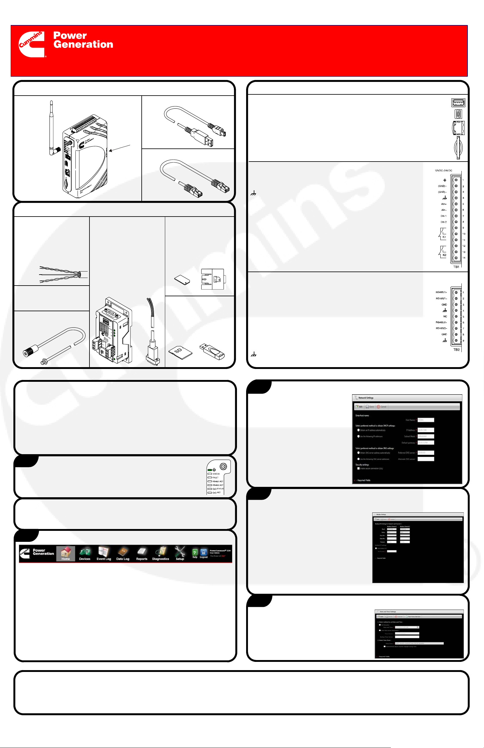
Verify Hardware Contents
Antenna
(CDMA
and GSM
only)
PowerCommand 550
Verify Additional Hardware Needed
Modbus Cable − Re-
quired shielded twisted
pair cable, 24 AWG or
larger, used to connect
PowerCommand
500/550 to monitored
device.
Power Supply (12−24V,
2A) − Required for all
installations.
Antenna Extension −
Required for cabinet
installations.
USB−OTG CablePowerCommand 500 or
SIM Card
Door
Ethernet Cable
ModLon II Gateway Kit
and ModLon Connection Cable (A040T087) −
Required for legacy controls (PCC2100, 3100,
3200, and 3201 generator set controls and
OTPC, BTPC, OHPC,
and CHPC transfer
switch controls).
SIM Card −
Required for GSM
cellular modem
(needs to be
obtained from your
local service
provider).
Secure Digital (SD)
Memory Card or
USB Flash Drive
(Optional) − Used as
external memory for
data logs.
Connections
PORTS:
External USB Memory: Insert a USB flash drive as external
memory for data logs.
USB Mini: This direct connection to PC is used to access User
Interface during initial configuration.
Ethernet: Used to connect to the network; it supports both IEEE 10
BASE-T and 100 BASE-TX standards.
SD Card Slot: Insert an SD card as external memory for data logs.
TB1 − INPUT/OUTPUT CONNECTIONS:
Input +: 12−24 VDC power supply or B+ battery.
Negative Ground (GND)−: GND from power supply or B− battery.
Chassis Ground: Connect to an earth grounded metal surface.
Analog Resistive Input (AIn+ and AIn−): Connection for a
resistive sensor into the PowerCommand 500/550 (600−2500
ohms).
Discrete Inputs (DIn 1 and DIn 2): Two isolated ‘open-collector’
type discrete inputs. These inputs are activated when connected to
the PowerCommand 500/550 GND (B− or power supply ground).
Discrete Outputs: K1 and K2 from the PowerCommand 500/550.
Pins 9 and 12 are common. Pins 10 and pins 14 are normally open.
Pins 11 and 13 are normally closed. Each output is rated at 1A 30
VDC, 0.3A 125 VAC (resolve load).
TB2 − COMMUNICATIONS TERMINAL:
RS485/1+ and RS485/1−, RS485/2+ and RS485/2−: Two sets of
connections are used to support Modbus communications with
PowerCommand controls on generator sets, transfer switches, or
AUX 101/102. Both the control and the PowerCommand 500/550
must have the same Modbus configuration (baud rate, parity bit,
and stop bit). Connections are made using the Modbus
communication cable.
GND (Ground): Ground reference between PowerCommand
500/550 and controls, depending on power supply configuration
(see External Connectivity Diagrams).
Chassis Ground: Connect to shield of the Modbus cable.
NC: Not used
Verify System Requirements
PC or Macintosh computer with CD drive
Browser: Internet Explorer 8 or later is recommended
Operating System: Microsoft Windows, Mac OS X, or Linux
Microsoft Silverlight software, version 5.0 or later
Minimum Screen Resolution: 1024 x 768
Windows Mobile Device Center
1
1. Connect the PowerCommand 500/550 to a power supply. Refer
to the Connections topic.
2. Check the Power LED to confirm power is available.
Connect to Power Supply
Note to Installer/Customer
Software setup (steps 2 through 10) can be completed before arriving at
the site and prior to physical installation.
2
1. Turn on the computer.
2. Connect PC500/550 to the Internet using an Ethernet cable.
3. Connect the USB−OTG cable from the PowerCommand 500/550 to the
computer. The computer automatically installs a software driver. If not,
install “Windows Mobile Device Center” manually.
4. Open an Internet browser window and go to Tools > Internet Options >
Connections > LAN Settings. Under Proxy Server, uncheck the box for
Use a Proxy server for your LAN.
5. In Internet browser address bar, enter the following IP address:
169.254.0.1 to load PowerCommand 500/550 login screen.
NOTE: Use https when SSL is enabled or http when it is disabled.
6. Enter the user name (admin) and password (admin).
Access the Home Page
3
1. Once the Home page
appears, select Setup on the
menu bar.
2. Select Network Settings in
the Setup menu.
3. Select Edit.
4. Enter network setting
information obtained from
your IT network administrator
or local service provider.
5. Select Save.
4
1. Navigate to Modbus Settings in the Setup menu. Default information is
displayed.
2. If any information needs to be changed,
select Edit.
3. Enter the Modbus Channel−1 and
Channel−2 information. Obtain from
service tool or applicable control HMI.
Also, enter the port number for Modbus
TCP.
4. Select Save.
5. All devices connected to same Modbus
channel must have same Modbus
Configuration (baud rate, parity, stop bits).
5
1. Navigate to Date and Time Settings
in the Setup menu.
2. Select Edit.
3. Select time method and enter any
required information.
4. Select Save.
Enter Network Settings
Modify Modbus Settings
Enter Date and Time Settings
Additional Information
If you have any questions regarding the installation, contact your nearest authorized Cummins distributor or dealer.
For additional information, refer to the PowerCommand 500/550 Owner Manual available on the Technical Publications CD.
For more information on Cummins products and services, go to www.power.cummins.com.
E 2014 Cummins Power Generation Inc. All rights reserved.
Cummins Power Generation and Cummins are registered trademarks of Cummins Inc. PowerCommand is a registered trademark of Cummins Power Generation
Printed in USA 1/2014 A040G393
English − Original Instructions
Page 2
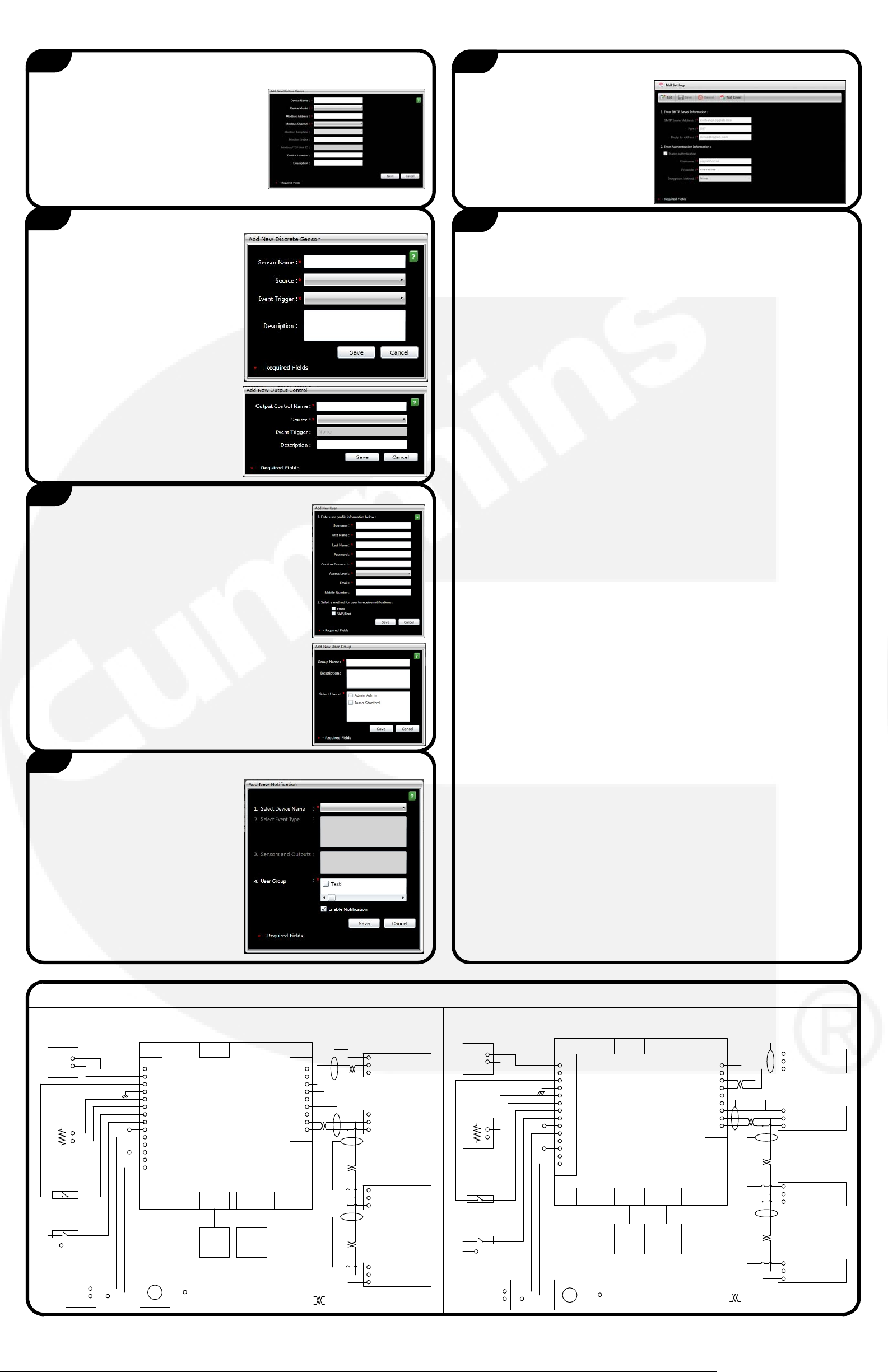
6
Add Devices
1. Navigate to Device Configuration in the Setup menu.
2. Select Add New Device.
3. Select the device type (Genset, ATS, I/O
Device) and enter the required
information for setting up the device.
4. Select Save.
5. Repeat steps 2 through 4 for each
additional Modbus device.
6. To view the devices, select Home on the menu bar.
10
Enter Mail Settings Information
1. Navigate to Mail Settings in the
Setup menu.
2. Select Edit.
3. Enter the SMTP server information.
4. Select Save.
7
Add Sensors and Outputs
1. Navigate to Sensors and Outputs in
the Setup menu.
2. To add a sensor, from the Inputs
tab, select Add New Sensor.
a. Select the sensor type
(Discrete or Analog) and enter
sensor information.
b. Select Save.
3. Repeat step 2 to add additional
sensors.
4. To add an output, from the
Outputs tab, select Add New
Output.
a. Enter output information.
b. Select Save.
5. Repeat step 4 to add additional
outputs.
8
Enter User/User Group Information
1. Navigate to User Profile Settings in the Setup
menu.
2. From the Users tab, select Add New User.
3. Enter the appropriate user information.
4. If the user is to receive notifications, select the
appropriate methods.
5. Select Save.
6. Repeat steps 2 through 5 to add additional users.
7. To create a group (for notifications), select the User
Groups tab.
8. Select Add New User Group.
9. Enter the user group name and select the users to
be included.
10.Select Save.
11. Repeat steps 7 through 10 to add additional user
groups.
11
Complete the Installation
1. After all configurations are complete, unplug the USB−OTG cable from the
PowerCommand 500/550. Then move PowerCommand 500/550 to the
installation site.
2. Connect the Ethernet cable from the PowerCommand 500/550 to the site’s
network (Ethernet hub/switch).
3. For the wireless option only (GSM or CDMA cell modems),
Open Installations − Attach antenna to the SMA connector on the
PowerCommand 500/550.
Metal Cabinet Installations − Choose a location for the antenna,
preferably near the top of the cabinet. Create a 9/32-inch (7mm) hole
and install the bulkhead end of the antenna extension cable. Connect
the other end to the SMA connector on the PowerCommand 500/550.
Attach the antenna to the connector on the outside of the cabinet.
Activate the modem. Refer to the Owner Manual for the appropriate
Modem Activation Process.
4. For installations that use legacy controls, install a ModLon II Gateway for
interfacing LonWorks to Modbus RTU communications. (See instructions
in Instruction Sheet C673.)
5. For wiring up the Modbus communication over RS-485, use 24 AWG or
larger, shielded, twisted pair cable. Both Modbus channels are located on
the TB2 connector.
Using a twisted pair of the Modbus cable, connect the RS-485 signal wires
from the generator set, ATS, or AUX101 control to the corresponding points
on the PowerCommand 500/550 terminal block. Either channel is acceptable,
provided it is consistent with information from step 7 (Add Devices).
Note: All devices wired to the same Modbus channel must have the same
Modbus configuration (baud rate, parity, stop bits). Multiple devices can be
wired over daisy chain before connecting to Channel−1 or Channel−2).
A ground reference wire may be necessary depending on the power supply
configuration. If the PowerCommand 500/550 is powered from the same
source as the connected PowerCommand Control, a ground wire is not needed. If the PowerCommand 500/550 uses a separate power supply, a ground
reference wire should be connected.
Connect the cable shield to either CGND on the PowerCommand 500/550, or
the ground pin on the generator set, ATS or AUX101 control, but not both.
Refer to the External Connectivity Diagrams for more information.
9
Enter Notification Information
1. Navigate to Notifications in the
Setup menu.
2. Select Add New Notification.
3. Select a Device Name and Event
Type.
4. To receive notifications, select a
user group and make sure
Enable Notifications is
checked.
5. Select Save.
6. Repeat steps 2 through 5 to add
6. If needed, use standard 24 AWG or larger wire to complete the following
PowerCommand 500/550 TB1 connections.
Wire the Analog Resistive Inputs to an appropriate sensor (for
example, a fuel sensor).
Wire Discrete Input(s) and Discrete Output(s) to the desired
device(s).
Refer to the External Connectivity Diagrams for common examples.
7. If needed, insert an SD card or USB flash drive as external memory for
data logs.
8. Connect the PowerCommand 500/550 to a 12/24VDC generator set
battery or an isolated DC power supply.
9. Mount the PowerCommand 500/550 on a DIN rail or place on flat surface
(rubber feet are provided underneath base).
additional notifications.
External Connectivity Diagrams
Common Power Supply: Separate Power Supply:
+
−
CGND to grounded
metal surface
Fuel
Direct
B−
Alarm
+
−
One of the
Generator
Set Batteries
B−
Shield
Shield Shield
Shield
Either type of shield
connection is acceptable.
Only one end is terminated.
The controls are powered
from the generator set
batteries with all B−
connections tied together.
Control
1 RS-485 1 GND
4 RS-485 1 −
3 RS-485 1 +
Control
1 RS-485 1 GND
4 RS-485 1 −
3 RS-485 1 +
Control
1 RS-485 1 GND
4 RS-485 1 −
3 RS-485 1 +
Control
1 RS-485 1 GND
4 RS-485 1 −
3 RS-485 1 +
TB1
B+
1
B−
B+
B+
B+
2
GND
3
GND
4
CGND
5
ANALOG IN+
6
ANALOG IN−
7
DIN 1
8
DIN 2
9
DOUT1 COMMON
10
DOUT1 NO
11
DOUT1 NC
12
DOUT2 COMMON
13
DOUT2 NO
14
DOUT2 NC
SIM
Card
RS-485 2 GND
RS-485 2 −
RS-485 2 +
RS-485 1 GND
RS-485 1 −
RS-485 1 +
CGND
NC
CGND
TB2
9
8
7
6
5
4
3
2
1
PowerCommand 550
Lamp
USB
Host
USB
Device
B−
PC
Ether-
net
Router/
Switch
SD
Card
= Twisted Pair
Battery
Level
Sensor
Resistive
Sensor Range
600 to 2500
Generic Switch
Grounding
Generic Switch
Remote
Grounding
Power
Supply
+
−
CGND to grounded
Fuel
Level
Sensor
Resistive
Sensor Range
600 to 2500
Generic Switch
Direct
Grounding
Generic Switch
PS−
Remote
Grounding
Alarm
+
−
metal surface
PS+
PS−
B+
PS+
PS−
TB1
B+
2
GND
3
GND
4
CGND
5
ANALOG IN+
6
ANALOG IN−
7
DIN 1
8
DIN 2
9
DOUT1 COMMON
10
DOUT1 NO
11
DOUT1 NC
12
DOUT2 COMMON
13
DOUT2 NO
14
DOUT2 NC
Lamp
USB
Host
SIM
Card
RS-485 2 GND
RS-485 2 −
RS-485 2 +
RS-485 1 GND
RS-485 1 −
RS-485 1 +
PowerCommand 550
USB
Device
B−
PC
Ether-
net
Router/
Switch
CGND
NC
CGND
SD
Card
TB2
91
8
7
6
5
4
3
2
1
Shield
Either type of shield
connection is acceptable.
Only one end is terminated.
Shield
The controls are powered
from the generator set
batteries with all B−
connections tied together.
Shield Shield
= Twisted Pair
Control
1 RS-485 1 GND
4 RS-485 1 −
3 RS-485 1 +
Control
1 RS-485 1 GND
4 RS-485 1 −
3 RS-485 1 +
Control
1 RS-485 1 GND
4 RS-485 1 −
3 RS-485 1 +
Control
1 RS-485 1 GND
4 RS-485 1 −
3 RS-485 1 +
 Loading...