

Page 1
PowerCommandr 500/550 Cloud Link
Quick Setup Guide
Remote Monitoring
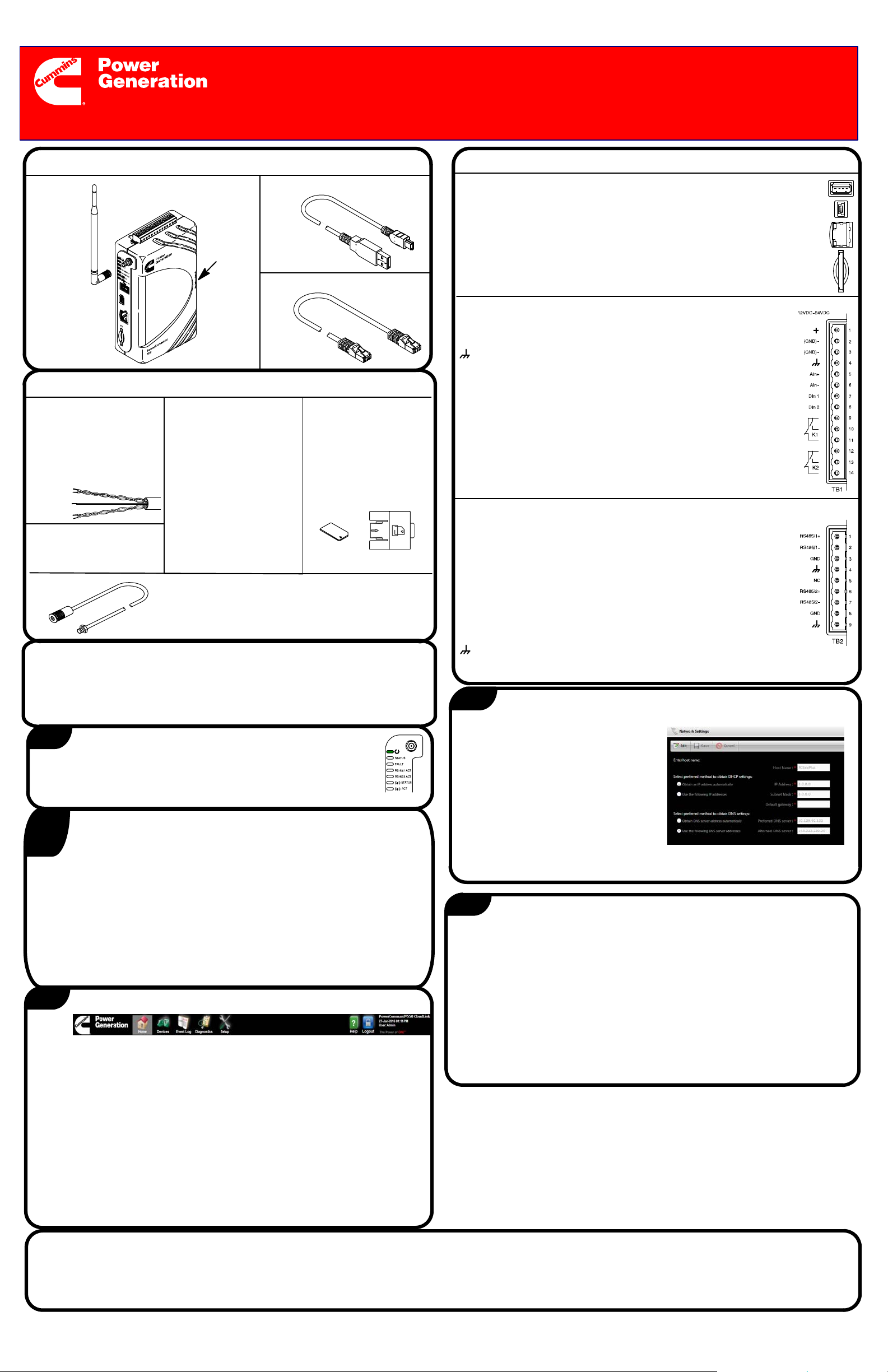
Verify Hardware Contents
Antenna
550 Cloud Link
SIM Card
Door
USB−OTG CablePowerCommand 500 or
Ethernet Cable
Verify Additional Hardware Needed
Modbus Cable − Re-
quired shielded twisted
pair cable, 24 AWG or
larger, used to connect
PowerCommand
500/550 to monitored
device.
Power Supply (9−32
VDC) − Required for all
installations.
Sierra ProtoNode
(A054V134) or ModLon
II Gateway Kit and ModLon Connection Cable
(A040T087) − Required
for legacy controls
(PCC2100, 3100, 3200,
and 3201 generator set
controls and OTPC,
BTPC, OHPC, and
CHPC transfer switch
controls).
Antenna Extension −
Required for cabinet
installations.
SIM Card −
Required for 3G
GSM Cellular
internet connection.
(Needs to be
obtained from your
local service
provider.)
Verify System Requirements
PC or Macintosh computer
Operating System: Microsoft Windows, Mac OS X, or Linux
Minimum Screen Resolution: 1024 x 768
Windows Mobile Device Center
Connections
PORTS:
External USB Memory: Not Used.
USB Mini: This direct connection to PC is used to access User
Interface during initial configuration.
Ethernet: Used to connect to the network; it supports both IEEE 10
BASE-T and 100 BASE-TX standards.
SD Card Slot: Not Used.
TB1 − INPUT/OUTPUT CONNECTIONS:
Input +: 9−32 VDC power supply or B+ battery.
Negative Ground (GND)−: GND from power supply or B− battery.
Chassis Ground: Connect to an earth grounded metal surface.
Analog Resistive Input (AIn+ and AIn−): Connection for a
resistive sensor into the PowerCommand 500/550 Cloud Link
(600−2500 ohms).
Discrete Inputs (DIn 1 and DIn 2): Two isolated ‘open-collector’
type discrete inputs. These inputs are activated when connected to
the PowerCommand 500/550 Cloud Link GND (B− or power supply
ground).
Discrete Outputs: Discrete outputs are used to support a ”wired
generator” configuration. See the Owners Manual for more
information on configuring a wired generator.
TB2 − COMMUNICATIONS TERMINAL:
RS485/1+ and RS485/1−, RS485/2+ and RS485/2−: Two sets of
connections are used to support Modbus communications with
PowerCommand controls on generator sets, transfer switches, or
AUX 101/102. Both the control and the PowerCommand 500/550
Cloud Link must have the same Modbus configuration (baud rate,
parity bit, and stop bit). Connections are made using the Modbus
communication cable.
GND (Ground): Ground reference between PowerCommand
500/550 Cloud Link and controls, depending on power supply
configuration (see External Connectivity Diagrams).
Chassis Ground: Connect to shield of the Modbus cable.
NC: Not used
4
Obtain an Internet Connection Via LAN
(For cellular installations, refer to section 5)
1
5. Connect the PowerCommand 500/550 Cloud Link to a 9−32V DC
power supply. Ensure that the Cloud Link remains powered in the
event of an outage.
6. Check the Power LED to confirm power is available.
2
Create the Customer Account and Site
Connect to Power Supply
(DEALER OR DISTRIBUTOR)
1. Navigate to https://Portal.PowerCommandCloud.com and sign in using the
link for employees/Dealers. Register for an employee/ Dealer account if
you do not have one.
2. Add a new Customer Account, this will generate an email invitation to the
customer for their account.
3. The customer must accept their invitation before you can add a Site to their
account.
4. Add a Site to the customers account. This will generate a Gateway Access
Key that you will need to establish Cloud Connectivity in section 6.
3
1. Turn on the computer.
2. Connect the USB−OTG cable from the PowerCommand 500/550 Cloud
Link to the computer. The computer automatically installs a software
driver. If not, install “Windows Mobile Device Center” manually.
3. Open an Internet browser window and go to Tools > Internet Options >
Connections > LAN Settings. Under Proxy Server, uncheck the box for
Use a Proxy server for your LAN.
4. In Internet browser address bar, enter the following IP address:
https://169.254.0.1 to load PowerCommand 500/550 Cloud Link login
screen.
NOTE: TLS is always enabled so https:// must be used to access the
device. Your browser may prompt you with a security warning, this is
normal and you must click to proceed.
5. Enter the user name (admin) and password (admin).
Access the Home Page
1. Select Network Settings in the
Setup menu.
2. Select Edit.
3. Enter network setting information
obtained from your IT network
administrator or local service
provider.
4. Select Save.
5. Confirm that there is network
connectivity (globe icon on top right)
5
Obtain an Internet Connection Via 3G Cellular
Only perform these steps if connecting to a cellular 3G network.
1. Install the included antenna.
2. Insert activated 3G SIM card into the SIM card slot of the PowerCommand
500/550 Cloud Link.
3. Select Cellular Preferences in the Setup menu.
4. Select Enable radio button to enable wireless data.
5. Obtain Access Point Name (APN) associated with your SIM card cellular
provider. This may be found online, or by contacting your provider. Enter
APN into the APN field.
6. Select Save.
7. Confirm that there is network connectivity (globe or 3G icon on top right).
Additional Information
If you have any questions regarding the installation, contact your nearest authorized Cummins distributor or dealer.
For additional information, refer to the PowerCommand 500/550 Cloud Link Owner Manual available on the Technical Publications CD.
For more information on Cummins products and services, go to www.power.cummins.com.
Copyright E 2017 Cummins Inc. All rights reserved.
Cummins, the “C” logo, PowerCommand, AmpSentry, and InPower are trademarks of Cummins Inc.
8−2017
A053H884 (Issue 2)
English − Original Instructions
Page 2
6
1. Confirm you have a valid internet connection before trying to connect to the
cloud.
2. Select Cloud Connectivity in the Setup menu.
3. Enter a Gateway Name. This name will identify the gateway on the
PowerCommand Cloud.
4. Retreive the Gateway Access Key from the PowerCommand Cloud. This
key is generated when you added a Site in section 2 above.
5. Paste the Gateway Access Key. Hold Ctrl and press V to paste.
6. Select SAVE.
7. Confirm that there is connectivity to the PowerCommand Cloud via the
cloud icon on the top right.
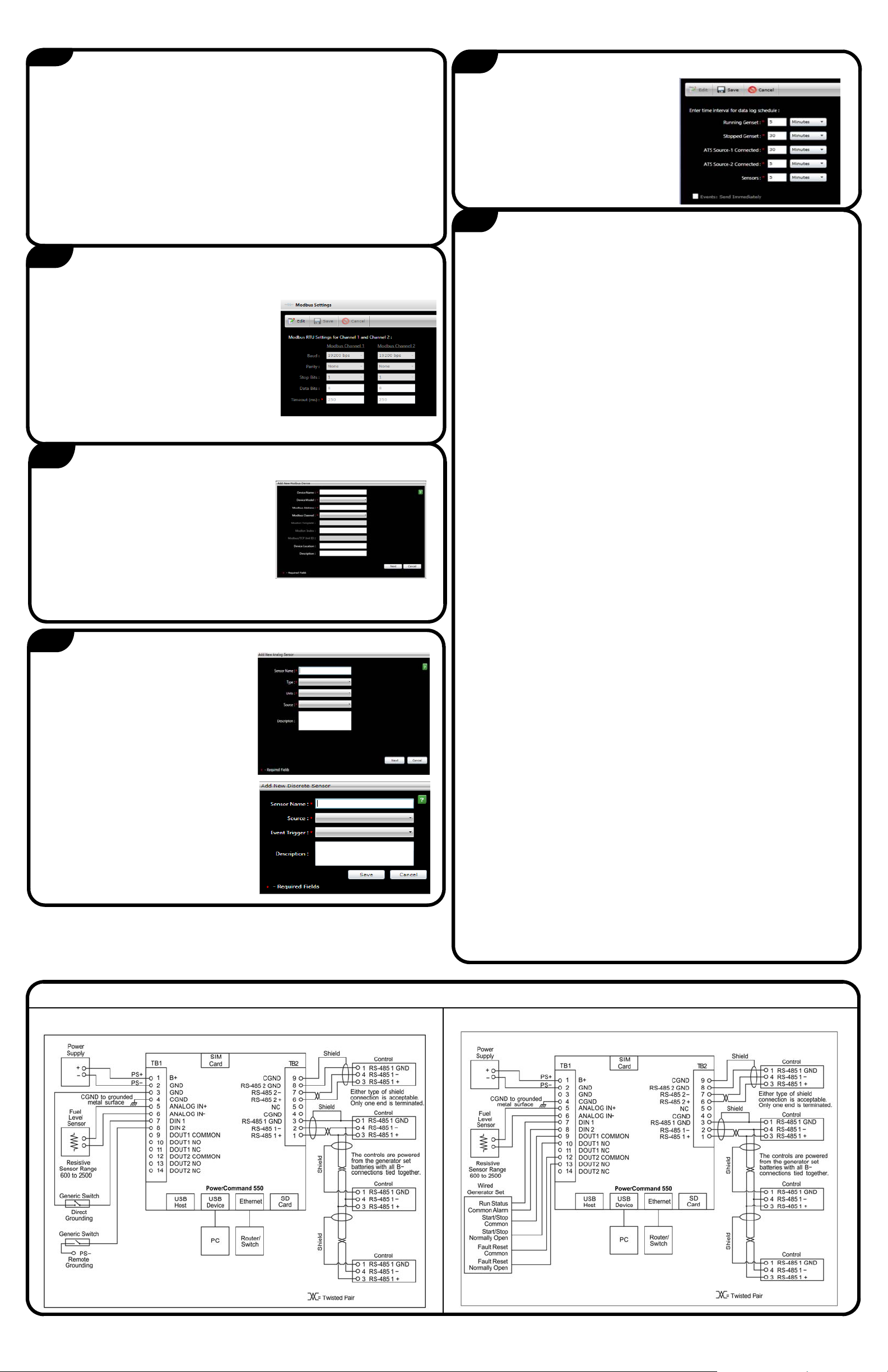
Establish Cloud Connectivity
10
1. Select Telemetry Settings from the
Setup menu.
2. For each category, specify the
desired time intervals that data will
be recorded in the Cloud.
NOTE: Shorter intervals lead to
higher data usage.
3. Select Save.
11
Configure Telemetry Settings
Complete the Installation
7
1. Select Modbus Settings in the Setup menu.
2. If any information needs to be changed,
select Edit.
3. Enter the Modbus Channel−1 and Channel−2
information. Obtain from service tool or
applicable control HMI.
4. Select Save.
5. All devices connected to same Modbus
channel must have same Modbus
Configuration (baud rate, parity, stop bits).
8
1. Select Device Configuration in the Setup menu.
2. Select Add New Device.
3. Select the device type (Genset, ATS, I/O
Device) and enter the required information
for setting up the device.
4. Select Save.
5. Repeat steps 2 through 4 for each
additional Modbus device.
6. Add your Devices on the PowerCommand Cloud by
navigating to the account Sites and selecting ADD
NEW ASSET.
9
1. Select Sensors and Output Controls
in the Setup menu.
2. To configure a Sensor, click on
Add New Sensor.
3. Select the Sensor type (Discrete or
Analog) and enter the sensor
source and information.
4. For Analog sensors, configure
Limits and warning thresholds.
5. Repeat steps 2−4 for any
additional sensors.
Configure Modbus Settings
Configure Devices
Configure Sensors
1. After all configurations are complete, unplug the USB−OTG cable from the
PowerCommand 500/550 Cloud Link. Then move PowerCommand
500/550 Cloud Link to the installation site.
2. For LAN installations, connect the Ethernet cable from the
PowerCommand 500/550 Cloud Link to the site’s network (Ethernet
hub/switch).
3. For 3G cellular installations:
Open Installations − Attach antenna to the SMA connector on the
PowerCommand 500/550 Cloud Link.
Metal Cabinet Installations − Choose a location for the antenna,
preferably near the top of the cabinet. Create a 9/32-inch (7mm) hole
and install the bulkhead end of the antenna extension cable. Connect
the other end to the SMA connector on the PowerCommand 500/550
Cloud Link. Attach the antenna to the connector on the outside of the
cabinet.
4. For installations that use legacy controls, install a Sierra ProtoNode or a
ModLon II Gateway for interfacing LonWorks to Modbus RTU
communications. (See instructions in Instruction Sheet C673.)
5. For wiring up the Modbus communication over RS-485, use 24 AWG or
larger, shielded, twisted pair cable. Both Modbus channels are located on
the TB2 connector.
Using a twisted pair of the Modbus cable, connect the RS-485 signal wires
from the generator set, ATS, or AUX101 control to the corresponding points
on the PowerCommand 500/550 Cloud Linkterminal block. Either channel is
acceptable, provided it is consistent with information from step 7 (Add Devices).
Note: All devices wired to the same Modbus channel must have the same
Modbus configuration (baud rate, parity, stop bits). Multiple devices can be
wired over daisy chain before connecting to Channel−1 or Channel−2).
A ground reference wire may be necessary depending on the power supply
configuration. If the PowerCommand 500/550 Cloud Link is powered from the
same source as the connected PowerCommand Control, a ground wire is not
needed. If the PowerCommand 500/550 Cloud Link uses a separate power
supply, a ground reference wire should be connected.
Connect the cable shield to either CGND on the PowerCommand 500/550
Cloud Link, or the ground pin on the generator set, ATS or AUX101 control,
but not both. Refer to the External Connectivity Diagrams for more information.
6. If needed, use standard 24 AWG or larger wire to complete the following
PowerCommand 500/550 Cloud Link TB1 connections.
Wire the Analog Resistive Inputs to an appropriate sensor (for
example, a fuel sensor).
Wire Discrete Input(s) and Discrete Output(s) to the desired
device(s).
Refer to the External Connectivity Diagrams for common examples.
7. Connect the PowerCommand 500/550 Cloud Link to a 12/24VDC
generator set battery or an isolated DC power supply.
8. Mount the PowerCommand 500/550 Cloud Link on a DIN rail or place on
flat surface (rubber feet are provided underneath base).
External Connectivity Diagrams
Analog and Discrete Sensor Inputs: Wired Generator:
 Loading...