

Page 1

Service Manual
Controller
PowerCommand 3201
Page 2
Table of Contents
SECTION TITLE PAGE
1. Introduction 1-1. . . . . . . . . . . . . . . . . . . . . . . . . . . . . . . . . . . . . . . . . . . . . . . . . . . . . . . . . . . .
ABOUT THIS MANUAL 1-1. . . . . . . . . . . . . . . . . . . . . . . . . . . . . . . . . . . . . . . . .
TEST EQUIPMENT 1-1. . . . . . . . . . . . . . . . . . . . . . . . . . . . . . . . . . . . . . . . . . . .
HOW TO OBTAIN SERVICE 1-1. . . . . . . . . . . . . . . . . . . . . . . . . . . . . . . . . . . . .
2. Control Operation 2-1. . . . . . . . . . . . . . . . . . . . . . . . . . . . . . . . . . . . . . . . . . . . . . . . . . . . . .
GENERAL 2-1. . . . . . . . . . . . . . . . . . . . . . . . . . . . . . . . . . . . . . . . . . . . . . . . . . . . .
SEQUENCE OF OPERATION 2-1. . . . . . . . . . . . . . . . . . . . . . . . . . . . . . . . . . . .
CONTROL PANEL POWER ON/OFF MODES 2-1. . . . . . . . . . . . . . . . . . . . .
CONTROL PANEL ASSEMBLY 2-4. . . . . . . . . . . . . . . . . . . . . . . . . . . . . . . . . .
READING FAULT CODES 2-6. . . . . . . . . . . . . . . . . . . . . . . . . . . . . . . . . . . . . . .
MENU DISPLAY AND SWITCHES 2-7. . . . . . . . . . . . . . . . . . . . . . . . . . . . . . . .
LANGUAGE/UNITS SELECTION MENU 2-8. . . . . . . . . . . . . . . . . . . . . . . . . .
MAIN MENU 2-9. . . . . . . . . . . . . . . . . . . . . . . . . . . . . . . . . . . . . . . . . . . . . . . . . . .
ENGINE SUBMENUS 2-11. . . . . . . . . . . . . . . . . . . . . . . . . . . . . . . . . . . . . . . . . .
ALTERNATOR SUBMENUS 2-12. . . . . . . . . . . . . . . . . . . . . . . . . . . . . . . . . . . .
CONTROL SUBMENU 2-13. . . . . . . . . . . . . . . . . . . . . . . . . . . . . . . . . . . . . . . . .
HISTORY/ABOUT SUBMENUS 2-14. . . . . . . . . . . . . . . . . . . . . . . . . . . . . . . . .
HISTORY/ABOUT SUBMENUS (CONT.) 2-15. . . . . . . . . . . . . . . . . . . . . . . . .
PARALLEL DATA SUBMENU 2-16. . . . . . . . . . . . . . . . . . . . . . . . . . . . . . . . . . .
POWER TRANSFER MAIN/SUBMENUS 2-17. . . . . . . . . . . . . . . . . . . . . . . . .
UTILITY (PWR TRAN) SUBMENUS 2-19. . . . . . . . . . . . . . . . . . . . . . . . . . . . .
STATUS (PWR TRAN) SUBMENUS 2-20. . . . . . . . . . . . . . . . . . . . . . . . . . . . .
TRANSFER CONTROL (PWR TRAN) SUBMENU 2-21. . . . . . . . . . . . . . . . .
GENSET (PWR TRAN) SUBMENUS 2-22. . . . . . . . . . . . . . . . . . . . . . . . . . . . .
3. Control Calibration and Adjustment 3-1. . . . . . . . . . . . . . . . . . . . . . . . . . . . . . . . . . . . .
GENERAL 3-1. . . . . . . . . . . . . . . . . . . . . . . . . . . . . . . . . . . . . . . . . . . . . . . . . . . . .
PARALLELING and NON−PARALLELING 3-1. . . . . . . . . . . . . . . . . . . . . . . . .
SOFTWARE CALIBRATIONS 3-1. . . . . . . . . . . . . . . . . . . . . . . . . . . . . . . . . . . .
MODIFYING SETUP/ADJUST SUBMENUS 3-1. . . . . . . . . . . . . . . . . . . . . . . .
SETUP MENUS 3-3. . . . . . . . . . . . . . . . . . . . . . . . . . . . . . . . . . . . . . . . . . . . . . . .
GOVERNING/VOLT REG SUBMENU 3-4. . . . . . . . . . . . . . . . . . . . . . . . . . . . .
CUSTOMER FAULTS SUBMENUS 3-6. . . . . . . . . . . . . . . . . . . . . . . . . . . . . . .
CALIBRATION SUBMENUS 3-8. . . . . . . . . . . . . . . . . . . . . . . . . . . . . . . . . . . . .
ISOLATED BUS SUBMENUS 3-11. . . . . . . . . . . . . . . . . . . . . . . . . . . . . . . . . . .
UTILITY SUBMENUS 3-17. . . . . . . . . . . . . . . . . . . . . . . . . . . . . . . . . . . . . . . . . .
POWER TRANSFER CONTROL MAIN MENUS 3-19. . . . . . . . . . . . . . . . . . .
UTILITY SENSORS SUBMENUS 3-20. . . . . . . . . . . . . . . . . . . . . . . . . . . . . . . .
GENSET SENSORS SUBMENUS 3-22. . . . . . . . . . . . . . . . . . . . . . . . . . . . . . .
TIMERS SUBMENU 3-24. . . . . . . . . . . . . . . . . . . . . . . . . . . . . . . . . . . . . . . . . . .
TEST/EXERCISE SUBMENU 3-26. . . . . . . . . . . . . . . . . . . . . . . . . . . . . . . . . . .
ADJUST SUBMENU 3-28. . . . . . . . . . . . . . . . . . . . . . . . . . . . . . . . . . . . . . . . . . .
CALIBRATION PROCEDURE 3-29. . . . . . . . . . . . . . . . . . . . . . . . . . . . . . . . . . .
i
Page 3

SECTION TITLE PAGE
CONTROL BOX WIRING 3-31. . . . . . . . . . . . . . . . . . . . . . . . . . . . . . . . . . . . . . .
RUN RELAYS (K11, K12, K13) 3-33. . . . . . . . . . . . . . . . . . . . . . . . . . . . . . . . . .
ALARM RELAY (K16) 3-34. . . . . . . . . . . . . . . . . . . . . . . . . . . . . . . . . . . . . . . . . .
MAGNETIC SPEED PICKUP UNIT (MPU) INSTALLATION 3-35. . . . . . . . .
ii
Page 4
IMPORTANT SAFETY INSTRUCTIONS
SAVE THESE INSTRUCTIONS − This manual contains
important instructions that should be followed during
installation and maintenance of the generator set and
batteries.
Before operating the generator set (genset), read the
Operator’s Manual and become familiar with it and the
equipment. Safe and efficient operation can be
achieved only if the equipment is properly operated
and maintained. Many accidents are caused by failure
to follow fundamental rules and precautions.
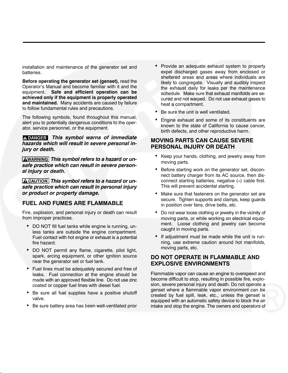
The following symbols, found throughout this manual,
alert you to potentially dangerous conditions to the oper-
ator, service personnel, or the equipment.
This symbol warns of immediate
hazards which will result in severe personal in-
jury or death.
WARNING
This symbol refers to a hazard or un-
safe practice which can result in severe person-
al injury or death.
CAUTION
This symbol refers to a hazard or un-
safe practice which can result in personal injury
or product or property damage.
FUEL AND FUMES ARE FLAMMABLE
Fire, explosion, and personal injury or death can result
from improper practices.
DO NOT fill fuel tanks while engine is running, un-
less tanks are outside the engine compartment.
Fuel contact with hot engine or exhaust is a potential
fire hazard.
DO NOT permit any flame, cigarette, pilot light,
spark, arcing equipment, or other ignition source
near the generator set or fuel tank.
Fuel lines must be adequately secured and free of
leaks. Fuel connection at the engine should be
made with an approved flexible line. Do not use zinc
coated or copper fuel lines with diesel fuel.
Be sure all fuel supplies have a positive shutoff
valve.
Be sure battery area has been well-ventilated prior
to servicing near it. Lead-acid batteries emit a highly
explosive hydrogen gas that can be ignited by arcing, sparking, smoking, etc.
EXHAUST GASES ARE DEADLY
Provide an adequate exhaust system to properly
expel discharged gases away from enclosed or
sheltered areas and areas where individuals are
likely to congregate. Visually and audibly inspect
the exhaust daily for leaks per the maintenance
schedule. Make sure that exhaust manifolds are se-
cured and not warped. Do not use exhaust gases to
heat a compartment.
Be sure the unit is well ventilated.
Engine exhaust and some of its constituents are
known to the state of California to cause cancer,
birth defects, and other reproductive harm.
MOVING PARTS CAN CAUSE SEVERE
PERSONAL INJURY OR DEATH
Keep your hands, clothing, and jewelry away from
moving parts.
Before starting work on the generator set, discon-
nect battery charger from its AC source, then dis-
connect starting batteries, negative (−) cable first.
This will prevent accidental starting.
Make sure that fasteners on the generator set are
secure. Tighten supports and clamps, keep guards
in position over fans, drive belts, etc.
Do not wear loose clothing or jewelry in the vicinity of
moving parts, or while working on electrical equip-
ment. Loose clothing and jewelry can become
caught in moving parts.
If adjustment must be made while the unit is run-
ning, use extreme caution around hot manifolds,
moving parts, etc.
DO NOT OPERATE IN FLAMMABLE AND
EXPLOSIVE ENVIRONMENTS
Flammable vapor can cause an engine to overspeed and
become difficult to stop, resulting in possible fire, explo-
sion, severe personal injury and death. Do not operate a
genset where a flammable vapor environment can be
created by fuel spill, leak, etc., unless the genset is
equipped with an automatic safety device to block the air
intake and stop the engine. The owners and operators of
the genset are solely responsible for operating the genset safely. Contact your authorized Cummins Power
Generation distributor for more information.
v
Page 5
ELECTRICAL SHOCK CAN CAUSE
SEVERE PERSONAL INJURY OR DEATH
Remove electric power before removing protective
shields or touching electrical equipment. Use rubber insulative mats placed on dry wood platforms
over floors that are metal or concrete when around
electrical equipment. Do not wear damp clothing
(particularly wet shoes) or allow skin surface to be
damp when handling electrical equipment. Do not
wear jewelry. Jewelry can short out electrical con-
tacts and cause shock or burning.
Use extreme caution when working on electrical
components. High voltages can cause injury or
death. DO NOT tamper with interlocks.
Follow all applicable state and local electrical
codes. Have all electrical installations performed by
a qualified licensed electrician. Tag and lock open
switches to avoid accidental closure.
DO NOT CONNECT GENERATOR SET DIRECT-
LY TO ANY BUILDING ELECTRICAL SYSTEM.
Hazardous voltages can flow from the generator set
into the utility line. This creates a potential for elec-
trocution or property damage. Connect only
through an approved isolation switch or an ap-
proved paralleling device.
GENERAL SAFETY PRECAUTIONS
Coolants under pressure have a higher boiling point
than water. DO NOT open a radiator or heat ex-
changer pressure cap while the engine is running.
To prevent severe scalding, let engine cool down
before removing coolant pressure cap. Turn cap
slowly, and do not open it fully until the pressure has
been relieved.
Used engine oils have been identified by some state
or federal agencies as causing cancer or reproduc-
tive toxicity. When checking or changing engine oil,
take care not to ingest, breathe the fumes, or con-
tact used oil.
Keep multi-class ABC fire extinguishers handy.
Class A fires involve ordinary combustible materials
such as wood and cloth; Class B fires, combustible
and flammable liquid fuels and gaseous fuels; Class
C fires, live electrical equipment. (ref. NFPA No. 10).
Make sure that rags or combustible material are not
left on or near the generator set.
Make sure generator set is mounted in a manner to
prevent combustible materials from accumulating
under or near the unit.
Remove all unnecessary grease and oil from the
unit. Accumulated grease and oil can cause over-
heating and engine damage which present a poten-
tial fire hazard.
Keep the generator set and the surrounding area
clean and free from obstructions. Remove any de-
bris from the set and keep the floor clean and dry.
Do not work on this equipment when mentally or
physically fatigued, or after consuming any alcohol
or drug that makes the operation of equipment un-
safe.
Substances in exhaust gases have been identified
by some state or federal agencies as causing can-
cer or reproductive toxicity. Take care not to breath
or ingest or come into contact with exhaust gases.
Do not store any flammable liquids, such as fuel,
cleaners, oil, etc., near the generator set. A fire or
explosion could result.
Wear hearing protection when near an operating
generator set.
To prevent serious burns, avoid contact with hot
metal parts such as radiator system, turbo charger
system and exhaust system.
KEEP THIS MANUAL NEAR THE GENSET FOR EASY REFERENCE
vi
Page 6

1. Introduction
ABOUT THIS MANUAL
This manual provides PowerCommand Control
3201 (PCC) calibration and adjustment proce-
dures, control operation, alternator test and repair
procedures.
Operating and maintenance instructions are in the
applicable Operator’s Manual.
Read Important Safety Instructions and carefully
observe all instructions and precautions in this
manual.
TEST EQUIPMENT
To perform the test procedures in this manual, the
following test equipment must be available
True RMS meter for accurate measurement of
small AC and DC voltages.
Battery Hydrometer
Jumper Leads
Tachometer or Frequency Meter
Wheatstone Bridge or Digital Ohmmeter
Variac
Load Test Panel
Megger or Insulation Resistance Meter
InPower Service Tool (PC based genset ser-
vice tool)
HOW TO OBTAIN SERVICE
Always give the complete Model, Specification and
Serial number of the generator set as shown on the
nameplate when seeking additional service infor-
mation or replacement parts. The nameplate is lo-
cated on the side of the generator output box.
WARNING
parts can result in severe personal injury or
death, and/or equipment damage. Service per-
sonnel must be trained and experienced to per-
form electrical and mechanical service. Read
and follow Important Safety Instructions, on
pages iii and iv.
Incorrect service or replacement of
1-1
Page 7

THIS PAGE LEFT INTENTIONALLY BLANK
1-2
Page 8
2. Control Operation
GENERAL
The following describes the function and operation
of the PowerCommand
dicators, control switches/buttons and graphical
display are located on the face of the control panel
as illustrated in Figure 2-1.
Normally, generator set configuration options are
set at the factory. When a new control is installed on
a generator set or when parts are replaced, the con-
trol must be configured for that generator set. Setup
and calibration procedures are described in Sec-
tion 3.
Control 3200 (PCC). All in-
SEQUENCE OF OPERATION
When the PowerCommand control is in the AUTO
mode, it will cause the generator set to start on re-
ceiving a signal from a remote device. The control
will initiate a starter cranking signal and verify that
the engine is rotating. The control will provide suffi-
cient fuel to the engine to accelerate to start discon-
nect speed. On reaching that speed, the control will
ramp the generator set to idle (warm-up) or rated
speed and voltage.
On reaching rated speed and voltage, the control
checks the system bus voltage. If no bus voltage is
present, it will wait for a pulse from a remote Master
First Start Sensor. On receiving that pulse, the control will signal the paralleling breaker to close.
If bus voltage is present, the control will check for
proper phase rotation, adjust the generator set to
the bus voltage and frequency level, and then syn-
chronize the generator set to the system bus. When
a synchronous condition is achieved, the control will
send a signal to close the paralleling breaker.
When the paralleling breaker is closed, the genera-
tor set will assume it’s proportional share of the total
load on the system bus.
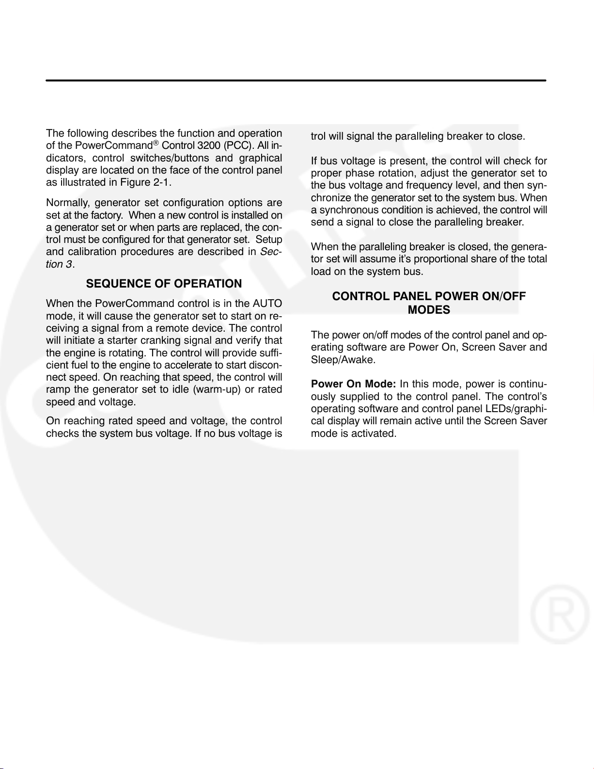
CONTROL PANEL POWER ON/OFF
MODES
The power on/off modes of the control panel and op-
erating software are Power On, Screen Saver and
Sleep/Awake.
Power On Mode: In this mode, power is continu-
ously supplied to the control panel. The control’s
operating software and control panel LEDs/graphi-
cal display will remain active until the Screen Saver
mode is activated.
2-1
Page 9

Screen Saver Mode: Power to the graphical dis-
play will be removed after 10 minutes (generator set
not running or running). The 10 minute timer resets
and begins after each control panel action (any button or switch selection) or signal received by the operating software. The bottom LEDs of the Analog
AC Metering Panel (bar graphs) may remain on dur-
ing Screen Saver mode, indicating that the operat-
ing software is active (Awake mode).
If these conditions are not met, Sleep mode is disabled in Auto mode.
The graphical display can enter Screen Saver mode
even if Sleep mode is disabled.
If Sleep mode is enabled in Auto mode, Sleep mode
is activated when there are no unacknowledged
faults and Screen Saver mode is active.
When a “Warning” signal is sensed by the PCC (for
example, low coolant temp), the control will display
the warning message. The control will remain active
until the Fault Acknowledge button is pressed to
clear the warning message and start the 10 minute
timer.
Sleep/Awake Mode: In the Sleep mode, the con-
trol’s operating software is inactive and the LEDs
and the graphical display on the control panel are all
off. Sleep mode is a feature that is used to reduce
battery power consumption when the control is not
being used.
In Off mode, Sleep mode is activated when there
are no unacknowledged faults and Screen Saver
mode is active.
In Auto mode, Sleep mode can be enabled or dis-
abled. When shipped from the factory, it is disabled.
You can enable Sleep mode by making these
changes:
Use InPower service tool to set Auto Sleep En-
able to Sleep in Auto.
Set switch S1 on the Genset/Paralleling Card
to Sleep/Off. This switch is located next to con-
nector J8 and relay K9.
The operating software is initialized and the control
panel LEDs and graphical display are turned on in
response to one of the following:
Moving/pressing any control panel switch/but-
ton. (If Sleep mode is enabled in Auto mode,
the control will remain asleep if Sleep mode
was previously active in Off mode.)
Receiving a remote start input signal (genera-
tor set in Auto mode)
Receiving an active DCD signal on the RS-232
port.
Modem RI latch becoming active.
Digital display waking up.
Lonworks (backplane) wakeup becoming ac-
tive.
Customer fault 2 or 3 only (shutdown or warn-
ing indicator is on).
Dial Out process becoming active.
To activate the control and view the menu display
without starting the generator set, press any button
on the control panel.
2-2
Page 10
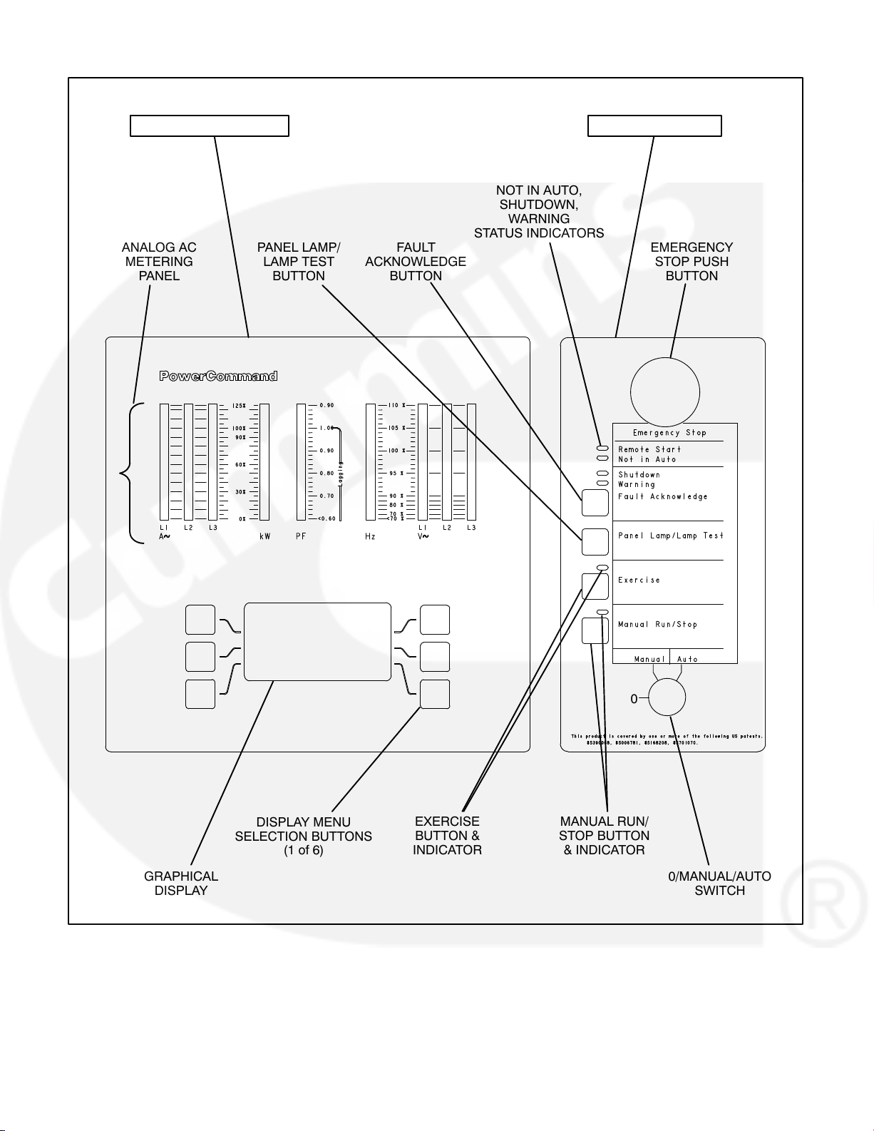
OPERATOR PANEL SWITCH PANEL
REMOTE START,
NOT IN AUTO,
SHUTDOWN,
WARNING
STATUS INDICATORS
ANALOG AC
METERING
PANEL
PANEL LAMP/
LAMP TEST
BUTTON
FAULT
ACKNOWLEDGE
BUTTON
EMERGENCY
STOP PUSH
BUTTON
GRAPHICAL
DISPLAY
0
DISPLAY MENU
SELECTION BUTTONS
(1 of 6)
EXERCISE
BUTTON &
INDICATOR
MANUAL RUN/
STOP BUTTON
& INDICATOR
FIGURE 2-1. CONTROL PANEL ASSEMBLY (FULL-FEATURED)
2-3
0/MANUAL/AUTO
SWITCH
Page 11

CONTROL PANEL ASSEMBLY
The control panel assembly (Figure 2-1) consist of
two panels, the Operator Panel and the Switch Pan-
el.
Dependent on site requirements, the Operator Pan-
el is either mounted on the control panel assembly
(full-featured) as shown in Figure 2-1 or contained
in a separate enclosure and mounted remotely of
the control panel assembly.
The function of several buttons on the control panel
will vary dependent on the location of the control
panel (remote or local of the control panel assem-
bly). If the function differs, it is noted as either “re-
mote” or “local operator panel” in the button de-
scription.
Operator Panel
The operator panel contains the following compo-
nents:
Analog AC Metering Panel: This panel simulta-
neously displays 3-phase line to line AC volts and
current, kW, power factor and frequency.
The meter panel is composed of a series of LEDs,
that are configured in bar graphs for each function.
The LEDs are color coded, with green indicating
normal range values, amber for warning levels and
red for shutdown conditions.
Scales for each function are in % of nominal values.
Resolution is 1% for values close to nominal, and increases at values further from nominal.
Graphical Display: The graphical display is capable of displaying up to 9-lines of data with approximately 27 characters per line. The display is used to
view the menus of the menu-driven operating sys-
tem.
The top three lines of the graphical display contain
the following control information in the order de-
scribed:
State Line − modes of operation, such as
Stopped, Time Delay To Start, Warm Up At
Idle, etc. (see Figure 2-2), and paralleling op-
erations, such as Standby, Dead BUS Close,
Synchronize, Load Share and Load Govern.
Action Line − system actions, such as Warning,
Derate, Shutdown Cool-down and Shutdown,
and fault codes.
Description Line − Fault code messages.
Display Menu Selection Buttons: Six momentary
buttons—three on each side of the graphical dis-
play window—are used to navigate through the sys-
tem control menus and to adjust generator set pa-
rameters. The button is active when the message
adjacent to the button is highlighted (displayed in in-
verse video).
2-4
Page 12
Switch Panel
The switch panel contains the following components:
Emergency Stop Button: Push the button in for
emergency shutdown of the engine. If the engine is
not running, pushing the button in will prevent the
starting of the engine, regardless of the start signal
source (local or remote).
Fault Acknowledge: Press this button to acknowledge warning and shutdown messages after the
fault has been corrected.
To acknowledge a Warning message, the 0/Manual/Auto switch can be in any position. (It is not nec-
essary to stop the generator set to acknowledge an
inactive Warning condition.) To acknowledge a
shutdown message with this button, the 0/Manual/
Auto switch must be in the 0 (Off) position.
To reset:
1. Pull the button out.
2. Move the 0/Manual/Auto switch to 0.
3. Press the front panel Fault Acknowledge
button.
4. Select Manual or Auto, as required.
Remote Start Indicator: This green lamp is lit
whenever the control is receiving a remote run sig-
nal. When flashing, it indicates a load demand stop
mode.
Not in Auto Indicator: This red lamp flashes con-
tinuously when the 0/Manual/Auto switch is not in
the Auto position. (If in Auto position and lamp is
flashing, service is required.)
Shutdown Status Indicator: This red lamp is lit
whenever the control detects a shutdown condition.
The generator set can not be started when this lamp
is on. After the condition is corrected, shutdown in-
dicators can be reset by turning the 0/Manual/Auto
switch to the 0 position, and pressing the Fault Ac-
knowledge button.
Dependent upon the specific fault that occurs, the
engine may or may not shut down immediately. A
fault that could cause engine damage, causes an
immediate engine shutdown (bypasses engine
cool-down sequence). All other faults would allow
the engine to run during the cool-down sequence
before engine shutdown. In this case, the Shutdown
Status Indicator blinks during the cooldown period.
This button is also used to blink a fault code if the
Shutdown or Warning Status Indicator is lit. (This
function is used when the control does not contain a
graphical display.) Refer to Reading Fault Codes in
this section, which describes how to use this button
for interpreting fault codes.
Panel Lamp/Lamp Test Button: Press this button
to turn on or off the panel lamp. Press and hold
down this button for three seconds or more to turn
all control panel LEDs on to make sure all lamps illu-
minate. The illumination will shut off after releasing
the button.
Exercise Button: Press this button to initiate a pre-
programmed exercise sequence. To start the exer-
cise sequence, press and hold down the Exercise
button and move the O/Manual/Auto switch from
Auto to Manual and back to Auto or from Manual to
Auto.
Manual Run/Stop Button: This button starts and
stops the set locally and will bypass Time Delay to
Start and Stop sequences. The 0/Manual/Auto
switch must be in the Manual position to enable this
button.
0/Manual/Auto Switch: Manual position enables
the use of the switch panel Manual Run/Stop but-
ton.
Auto position enables start/stop control of the en-
gine from a remote location. (Disables the use of the
switch panel Manual Run/Stop button.)
Warning Status Indicator: This yellow lamp is lit
whenever the control detects a warning condition.
After the condition is corrected, warning indicators
can be reset by pressing the Fault Acknowledge
button. (It is not necessary to stop the generator set
if the fault becomes inactive during genset opera-
tion.)
0 (Off) position prevents the starting of the set (local
or remote). If moved to 0 during set operation, will
cause an immediate engine shutdown (bypasses
cool-down timers). This hot shutdown should be
avoided, if possible, to help prolong the life of the
engine. Hot shutdowns are logged by the system
software.
2-5
Page 13
READING FAULT CODES
If the genset contains the optional graphical display
and a fault occurs, the fault code/message will be
displayed in the display Description Line (Figure
2-2). If the control does not contain the graphical
display, the fault code is read from the Warning and
Shutdown status indicators.
A three digit fault code is indicated by three sets of
blinks separated by a two second pause. The first
set corresponds to the hundreds position, the second to the tens position and the third to the ones digit. Example for Code No. 213:
Shutdown LED:
blink-blink-pause-blink-pause-blink-blink-blink
Reading Fault codes Using Warning/Shutdown
Indicators: If the Warning or Shutdown status indi-
cator is lit, press and hold the Fault Acknowledge
button and release after one second or more. After
one second, the Shutdown lamp will begin to blink
the active fault code(s) as follows.
The Warning lamp is used to indicate the start of a
new code. The Warning lamp will remain on for 2
seconds, followed by the Shutdown lamp blinking
the fault code. This sequence occurs three times for
each code. The fourth flash of the Warning lamp in-
dicates the beginning of the second fault code.
There are distinct pauses between repetitions of the
code blink transmissions of the Shutdown lamp.
Warning LED:
blink (2 seconds)
The light will display the fault codes (active or inac-
tive) in succession, starting with the most recent. Up
to 32 (unacknowledged) fault codes can be stored
in control panel memory.
To return the control to the most recent fault code,
press and release the Fault Acknowledge button
(less than one second) and repeat procedure.
When the fault code is acknowledged and cor-
rected, the recorded fault will be deleted from the
LED fault log, but will remain in a data log that main-
tains a fault code history. (The InPower service tool
is required to view this data log.)
2-6
Page 14
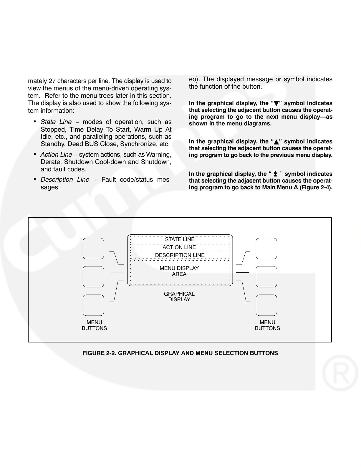
MENU DISPLAY AND SWITCHES
Figure 2-2 shows the graphical display and the
menu selection buttons.
Graphical Display: The graphical display is capable of displaying up to 9-lines of data with approximately 27 characters per line. The display is used to
view the menus of the menu-driven operating sys-
tem. Refer to the menu trees later in this section.
The display is also used to show the following sys-
tem information:
State Line − modes of operation, such as
Stopped, Time Delay To Start, Warm Up At
Idle, etc., and paralleling operations, such as
Standby, Dead BUS Close, Synchronize, etc.
Action Line − system actions, such as Warning,
Derate, Shutdown Cool-down and Shutdown,
and fault codes.
Description Line − Fault code/status mes-
sages.
Menu Buttons: Six momentary buttons—three on
each side of the graphical display window—are
used to navigate through the system control menus
and to adjust generator set parameters. The button
is active when the message or symbol adjacent to
the switch is highlighted (displayed in inverse video). The displayed message or symbol indicates
the function of the button.
In the graphical display, the “B” symbol indicates
that selecting the adjacent button causes the operat-
ing program to go to the next menu display—as
shown in the menu diagrams.
In the graphical display, the “Y” symbol indicates
that selecting the adjacent button causes the operat-
ing program to go back to the previous menu display.
In the graphical display, the “
that selecting the adjacent button causes the operat-
ing program to go back to Main Menu A (Figure 2-4).
” symbol indicates
STATE LINE
ACTION LINE
DESCRIPTION LINE
MENU DISPLAY
AREA
GRAPHICAL
DISPLAY
MENU
BUTTONS
FIGURE 2-2. GRAPHICAL DISPLAY AND MENU SELECTION BUTTONS
MENU
BUTTONS
2-7
Page 15
LANGUAGE/UNITS SELECTION MENU
During any control panel operation, you can select
one of three languages and change how units are
displayed by pressing the two lower menu buttons
(one on each side of display). When pressing these
two buttons simultaneously, the language/units
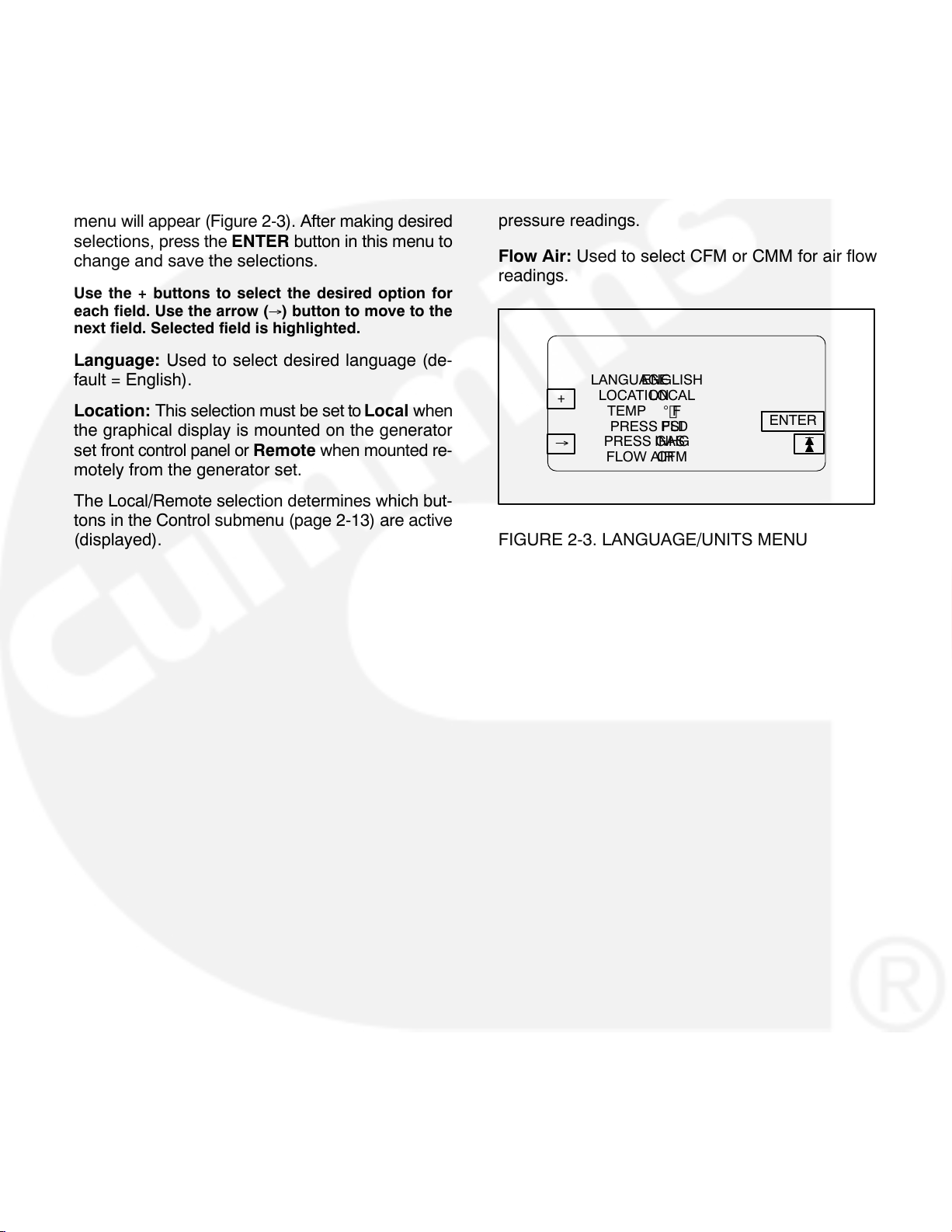
menu will appear (Figure 2-3). After making desired
selections, press the ENTER button in this menu to
change and save the selections.
Use the + buttons to select the desired option for
each field. Use the arrow (
next field. Selected field is highlighted.
Language: Used to select desired language (de-
fault = English).
Location: This selection must be set to Local when
the graphical display is mounted on the generator
set front control panel or Remote when mounted re-
motely from the generator set.
The Local/Remote selection determines which but-
tons in the Control submenu (page 2-13) are active
(displayed).
) button to move to the
Temp: Used to select F or C for temperature read-
ings.
Pressure Fluid: Used to select PSI, KPA, BAR or
IN for pressure readings.
Pressure Gas: Used to select INHG or MMHG for
pressure readings.
Flow Air: Used to select CFM or CMM for air flow
readings.
LANGUAGEENGLISH
LOCATIONLOCAL
+
TEMP F
PRESS FLDPSI
PRESS GASINHG
FLOW AIRCFM
ENTER
FIGURE 2-3. LANGUAGE/UNITS MENU
2-8
Page 16
MAIN MENU
_\_ Button (Paralleling Applications Only)
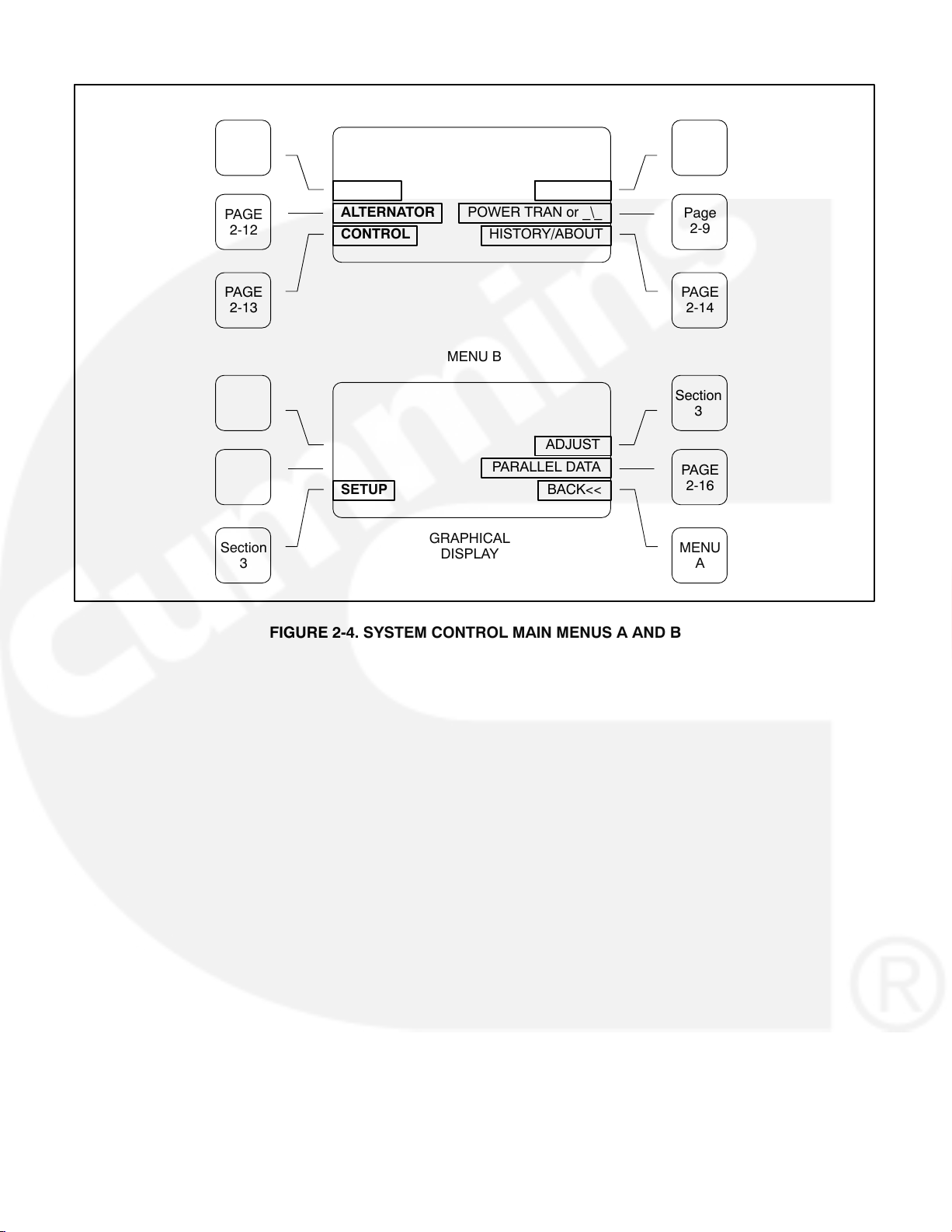
Figure 2-4 shows the main menus (Menu A and
Menu B) of the system control. The two main menus
are used to divide the system submenus into major
categories, such as, Engine Data, Alternator Data,
Control, etc.
To view system data, simply press the appropriate
menu button to select the category. After pressing
the desired menu button, refer to the page number
shown in Figure 2-4 for detailed information related
to the selected category.
In the following figures, the boxed/highlighted field
indicates that the adjacent menu button is active.
Also, the submenus are shown in the order in which
they are displayed when scrolling up
Y or down B.
Adjust Button
The Adjust submenu is intended for qualified site
personnel only. Note that a password may be as-
signed to allow only authorized operators to modify
this data. (Password is not required if not assigned.)
Setup Button
When displayed, indicates that the feature for generator set paralleling applications is installed. This
button is used to open and close the generator set
circuit breaker (CB). The symbol indicates if the CB
is opened or closed. Opened _\_, push to close.
Closed _−_, push to open.
With the control panel 0/Manual/Auto switch in the
Auto position, the opening and closing of the CB is
controlled by the control system software. The CB
symbol will indicate an open or closed CB, but the
button will be inactive when the control is in Auto.
In the Manual position, the CB can only be closed
by using this button. When manually closed and the
CB opens, it must be closed again by using this but-
ton. To close the CB, press and hold the button until
the symbol indicates a closed CB. (CB close will oc-
cur only when setup conditions allow − dead bus or
generator synchronized with bus.)
Power Trans Button (Power Transfer
Control Applications Only)
The Setup submenu is described in Section 3.
The “Adjust” and “Setup” submenus can be viewed,
but not modified without entering the correct pass-
words.
When displayed, indicates that the Power Transfer
Control (PTC) feature is installed. Refer to page
2-17 for PTC Data submenu description. The PTC
setup submenu is described in Section 3.
2-9
Page 17
MENU
BUTTONS
PAGE
2-11
MENU A
MENU
B
MENU
BUTTONS
PAGE
2-12
PAGE
2-13
Section
3
ENGINE
ALTERNATOR
CONTROL
SETUP
POWER TRAN or _\_
HISTORY/ABOUT
MENU B
PARALLEL DATA
GRAPHICAL
DISPLAY
MORE>>
ADJUST
BACK<<
FIGURE 2-4. SYSTEM CONTROL MAIN MENUS A AND B
Page
2-9
PAGE
2-14
Section
3
PAGE
2-16
MENU
A
2-10
Page 18
ENGINE SUBMENUS
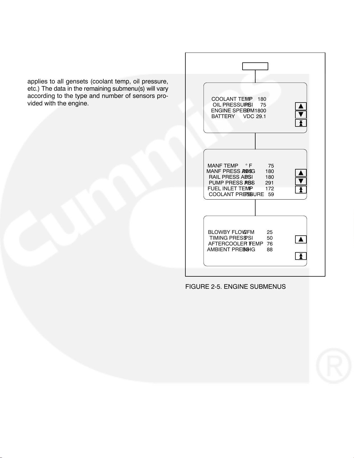
If you press the “ENGINE” button in Menu A, the Engine submenus will appear (Figure 2-5).
The first submenu displays general information that
applies to all gensets (coolant temp, oil pressure,
etc.) The data in the remaining submenu(s) will vary
according to the type and number of sensors pro-
vided with the engine.
ENGINE
COOLANT TEMP 180 F
OIL PRESSURE 75PSI
ENGINE SPEED 1800RPM
BATTERY 29.1VDC
MANF TEMP 75 F
MANF PRESS ABS 180INHG
RAIL PRESS ABS 180PSI
PUMP PRESS ABS 291PSI
FUEL INLET TEMP 172 F
COOLANT PRESSURE 59PSI
Y
B
Y
B
BLOWBY FLOW 25CFM
TIMING PRESS 50PSI
AFTERCOOLER TEMP 76 F
AMBIENT PRESS 88INHG
FIGURE 2-5. ENGINE SUBMENUS
Y
2-11
Page 19
ALTERNATOR SUBMENUS
If you press the “ALTERNATOR” button in Menu A,
the Alternator Data submenus will appear (Figure
2-6).
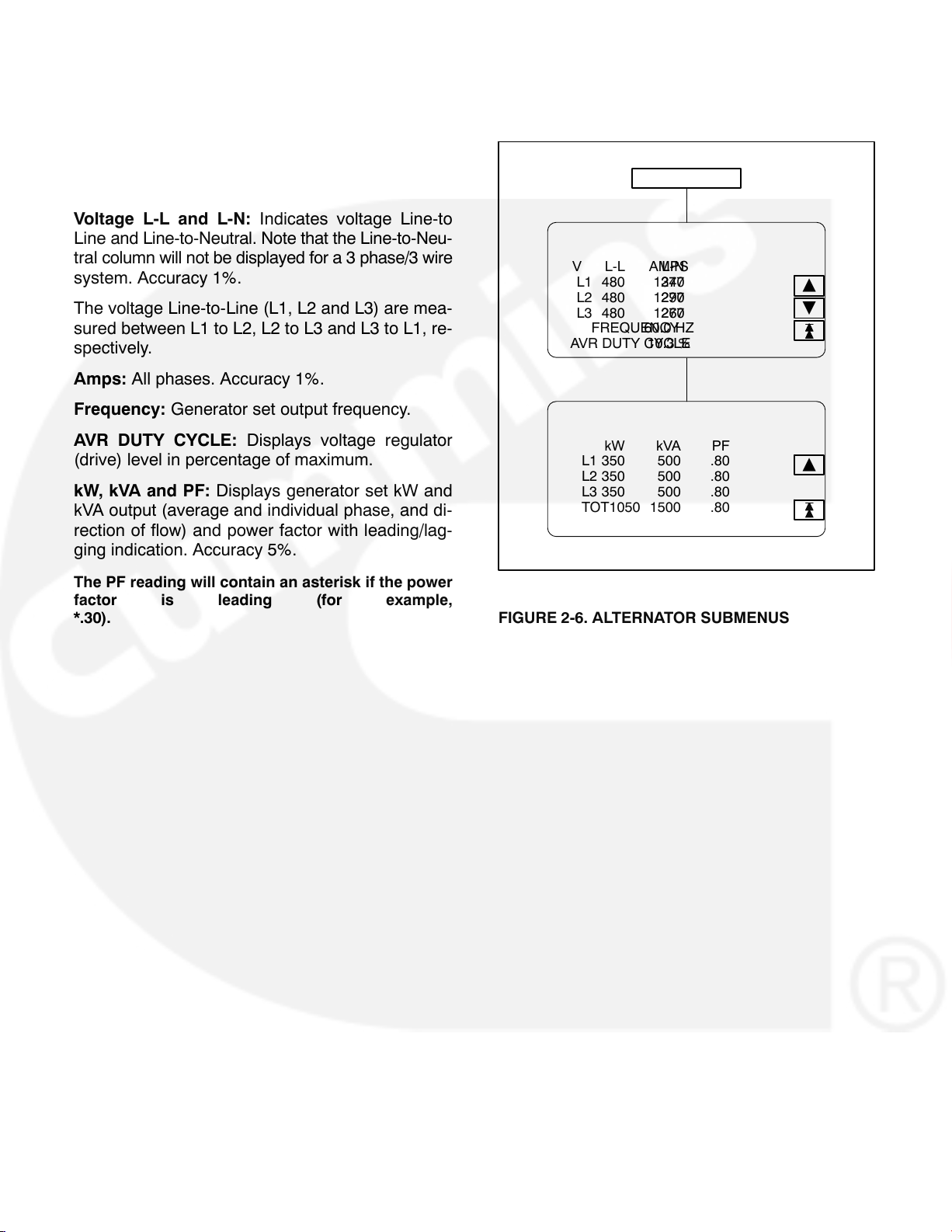
Voltage L-L and L-N: Indicates voltage Line-to
Line and Line-to-Neutral. Note that the Line-to-Neu-
tral column will not be displayed for a 3 phase/3 wire
system. Accuracy 1%.
The voltage Line-to-Line (L1, L2 and L3) are mea-
sured between L1 to L2, L2 to L3 and L3 to L1, re-
spectively.
Amps: All phases. Accuracy 1%.
Frequency: Generator set output frequency.
ALTERNATOR
V L-L L-NAMPS
L1 480 2771340
L2 480 2771290
L3 480 2771260
FREQUENCY60.0 HZ
AVR DUTY CYCLE10.3 %
Y
B
AVR DUTY CYCLE: Displays voltage regulator
(drive) level in percentage of maximum.
kW, kVA and PF: Displays generator set kW and
kVA output (average and individual phase, and di-
rection of flow) and power factor with leading/lag-
ging indication. Accuracy 5%.
The PF reading will contain an asterisk if the power
factor is leading (for example,
*.30).
kW kVA PF
L1 350 500 .80
L2 350 500 .80
L3 350 500 .80
TOT1050 1500 .80
FIGURE 2-6. ALTERNATOR SUBMENUS
Y
2-12
Page 20
CONTROL SUBMENU
If you press the “CONTROL” button in Menu A, the
Control submenu will appear (Figure 2-7).
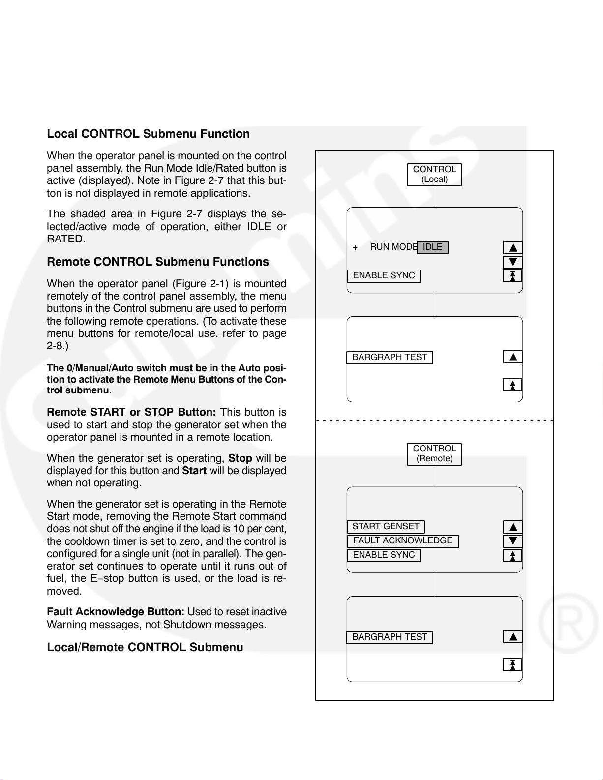
Local CONTROL Submenu Function
When the operator panel is mounted on the control
panel assembly, the Run Mode Idle/Rated button is
active (displayed). Note in Figure 2-7 that this but-
ton is not displayed in remote applications.
The shaded area in Figure 2-7 displays the se-
lected/active mode of operation, either IDLE or
RATED.
Remote CONTROL Submenu Functions
When the operator panel (Figure 2-1) is mounted
remotely of the control panel assembly, the menu
buttons in the Control submenu are used to perform
the following remote operations. (To activate these
menu buttons for remote/local use, refer to page
2-8.)
The 0/Manual/Auto switch must be in the Auto posi-
tion to activate the Remote Menu Buttons of the Con-
trol submenu.
Enable Sync: Displayed in paralleling applications
only. Intended for service personnel to turn off the
synchronizer for troubleshooting/testing purposes.
CONTROL
(Local)
+ RUN MODE IDLE
ENABLE SYNC
BARGRAPH TEST
YYY
B
Y
Remote START or STOP Button: This button is
used to start and stop the generator set when the
operator panel is mounted in a remote location.
When the generator set is operating, Stop will be
displayed for this button and Start will be displayed
when not operating.
When the generator set is operating in the Remote
Start mode, removing the Remote Start command
does not shut off the engine if the load is 10 per cent,
the cooldown timer is set to zero, and the control is
configured for a single unit (not in parallel). The gen-
erator set continues to operate until it runs out of
fuel, the E−stop button is used, or the load is re-
moved.
Fault Acknowledge Button: Used to reset inactive
Warning messages, not Shutdown messages.
Local/Remote CONTROL Submenu
Function
Bargraph Test: The function of this button remains
the same and is not dependent on operator panel
location. This button sequentially lights the LEDs to
test the bar graph display.
CONTROL
(Remote)
START GENSET
FAULT ACKNOWLEDGE
ENABLE SYNC
BARGRAPH TEST
FIGURE 2-7. CONTROL SUBMENU
B
Y
2-13
Page 21

HISTORY/ABOUT SUBMENUS
If you press the “HISTORY/ABOUT” button in Menu
A, the History/About submenus will appear (Figure
2-8).
HISTORY: The control maintains a data log of the
number of engine starts and number of operating
hours for the engine and control, and the megawatt
and maximum torque hours of the generator set.
This information is stored in non-volatile memory
and will not be deleted due to loss of battery power.
ABOUT: The About submenus provide the follow-
ing generator set information.
Genset model and wattage (kW/MW)
Output voltage and WYE, DELTA or SINGLE
Frequency 50 or 60 Hz
Rating: Standby, Prime or Base
Version level of the controller and panel operat-
ing software.
HISTORY/ABOUT
STARTS 533
ENGINE HOURS1236
CONTROL HOURS7879
KWHRS 890
HISTORY-HRS@ %MAX TORQUE
12345@0-923455@50-59
12345@10-1912345@60-69
12345@20-2912345@70-79
12345@30-3912345@80-89
Y
B
Y
B
MODEL 1750DQKB
VOLTAGE416 WYE
FREQUENCY60
RATINGSTANDBY
CONTROLLER VERSION
RTOPDN30008.DFA
BATSAPR 23 1999
OP PANEL VERSION
RTOP1.09 AUG 17 1999
BATS1.02 MAY 6 1999
CONTINUED TO NEXT PAGE
Y
B
Y
B
FIGURE 2-8. HISTORY/ABOUT SUBMENUS
2-14
Page 22

HISTORY/ABOUT SUBMENUS (CONT.)
FAULT HISTORY: The control maintains a data log
of all fault conditions as they occur, and time stamps
them with the control and engine operating hours.
Up to 32 (unacknowledged) fault codes can be
stored in control panel memory. After the fault is ac-
knowledged and corrected, the recorded fault will
be deleted from the control panel memory, but will
remain in a data log that maintains a fault code his-
tory. (The InPower service tool is required to view
this data log.)
The Fault History display line: 1 of 24 indicates that
24 faults are recorded and that the most recent fault
(1) detected by the controller is displayed.
The Occurrences display line: In this example, 5 in-
dicates that this is the fifth occurrence of this fault.
(The InPower service tool is required to review the
last four faults of this code.)
The Occurrences number is incremented for each
new occurrence of the same fault. The controller
must detect that the original sensed fault is cor-
rected before it will increment the occurrence num-
ber for that fault.
HISTORY/ABOUT (CONT.)
FAULT HISTORY: 1 OF 24
CNTL HOURS459
+
OCCURRENCES5
ENGINE HOURS334
FAULT CODE1437
(FAULT DESCRIPTION)
FIGURE 2-8. HISTORY/ABOUT SUBMENUS (CONT.)
Y
For example, when a Low Oil Pressure fault is de-
tected, the controller will increment the Occurrences
number by 1. This fault will remain active until the
fault is acknowledged and the controller detects that
the fault is corrected. An active fault will prevent the
controller from incrementing the Occurrences num-
ber each time the engine is started. When the con-
troller detects that the oil pressure is normal the fault
will become inactive, allowing the occurrences num-
ber to be incremented for the next detected Low Oil
Pressure
fault.
2-15
Page 23

PARALLEL DATA SUBMENU
If you press the “PARALLEL DATA” button in Menu
B, the Parallel Data submenu will appear (Figure
2-9). This menu is displayed in paralleling applications only.
_\_ Button: Used to open and close the generator
set circuit breaker (CB). The symbol indicates if the
CB is opened or closed. Opened _\_, push to close.
Closed _−_, push to open.
PARALLEL DATA STATUS LINE: The top line of
the graphical display is used to indicate the follow-
ing PARALLEL DATA status:
− STANDBY: Indicates no paralleling activity is
occurring at present.
− DEAD BUS CLOSE: Indicates first genset in
system to close to bus.
− SYNCHRONIZE: Genset is synchronizing to
bus.
− LOAD SHARE: Genset has closed to bus and
is sharing load with other gensets in system.
− LOAD GOVERN: Genset closed to bus in par-
allel with utility (mains).
BUS Voltage L-L: The BUS voltage Line-to-Line
(L1, L2 and L3) are measured between L1 to L2, L2
to L3 and L3 to L1, respectively.
BUS/GEN HZ: BUS/GEN hertz.
BUS/GEN SYNC STATUS: The bottom line of the
graphical display is used to indicate the following
BUS/GEN Sync status:
− NOT SYNCHRONIZING: Genset is in service
mode that does not allow auto sync feature.
(Selected via InPower service tool − deactivate
to allow synchronization.)
− SYNCHRONIZING: Genset is synchronizing to
bus.
− READY TO CLOSE: In manual mode, push cir-
cuit breaker close button to close breaker.
With the control panel 0/Manual/Auto switch in the
Auto position, the opening and closing of the CB is
controlled by the control system software. The CB
symbol will indicate an open or closed CB, but the
button will be inactive when the control is in Auto.
In the Manual position, the CB must be closed by
this button. When manually closed and the CB
opens, it must be closed again by using this button.
To close the CB, press and hold the button until the
symbol indicates a closed CB. (CB close will occur
only when setup conditions allow − dead bus or
generator synchronized with bus.)
PARALLEL DATA
LOAD GOVERN
V BUS GEN
L1 480 480
L2 480 480
L3 480 480
HZ60.1 60.1
DEG −122 NOT SYNCHRONIZING
Y
_\_
FIGURE 2-9. BUS DATA SUBMENU
2-16
Page 24

POWER TRANSFER MAIN/SUBMENUS
If you press the “POWER TRANS” button in Menu
A, the Power Transfer main menu will appear (Figure 2-10). The Power Transfer Control (PTC) feature must be installed to display this menu.
The PTC feature enables the PCC to monitor the
utility voltage (mains) and frequency for failure and
control the opening and closing of the contacts (cir-
cuit breakers) for the utility (S1) and the genset
(S2).
If utility fails, the control will initiate the genset start-
ing sequence, open S1 and close S2 to the load.
When utility returns, the load is retransferred to the
utility (S1 closes/S2 opens) and the control initiates
the genset shutdown sequence.
The
er Transfer main menu indicates which breaker
(utility or genset) is closed/opened to the load. The
symbol presently shown indicates that the utility
breaker is closed and supplying power to the load.
The Power Transfer main menu also indicates if the
utility and the generator set are available to accept
load. When the control detects that either source is
ready to accept load, UTILITY and/or GENSET will
be displayed in inverse video.
The Power Transfer main menu has four submenu
groups. Refer to the page numbers shown in Figure
2-10 for the Power Transfer submenu descriptions.
symbol displayed in the middle of the Pow-
2-17
Page 25

PTC Status Line
The top line of the graphical display is used to indicate the following PTC status:
− NOT ENABLED: PTC is not enabled. Control
panel switch in O (Off) position.
− MANUAL: Control panel switch is in Manual
position. All PTC actions or genset start/stop
actions are manually controlled.
− NORMAL UTIL: Load is connected to the util-
ity.
− RETRAN: Retransfer of load to utility.
− RETRAN OVRD: Immediate retransfer of load
to utility due to genset fault (e.g., warning, der-
ate, or shutdown w/cooldown fault). The re-
transfer timer is ignored as is the retransfer in-
hibit.
− EMERG TEST: Emergency Test sequence ini-
tiated through Remote Start switch with emer-
gency start sequence enabled (TB8-3 terminal
opened). Emergency test mode means that
the genset will continue to run even if a genset
warning or derate fault occurs. This test can be
performed with or without load (refer to TEST/
EXERCISE submenu in Section 3).
− TEST: Test sequence initiated through Remote
Start switch with emergency start sequence
disabled (TB8-3 terminal closed). Test mode is
non-emergency, which means that a retransfer
to utility will occur if any problems occur with
the genset while testing with load. This test can
be performed with or without load (refer to
TEST/EXERCISE submenu in Section 3).
− EXERCISE: Exercise sequence initiated
through control panel. This test can be per-
formed with or without load (refer to TEST/EX-
ERCISE submenu in Section 3). A retransfer to
utility will occur if any problems occur with the
genset during the exercise sequence.
− UTILITY FAIL: Utility has failed. (Initiates
transfer of load to genset if O/MANUAL/AUTO
switch is in AUTO.)
MENU
BUTTONS
PAGE
2-19
PAGE
2-20
PAGE
2-21
PTC STATUS LINE
B UTILITY
STATUS
TRANSFER CONTROL
DEG −123 SYNCHRONIZING
FIGURE 2-10. POWER TRANSFER MAIN MENU
GENSET B
PAGE
2-22
MENU
A
MENU
BUTTONS
2-18
Page 26

UTILITY (PWR TRAN) SUBMENUS
If you press the “Utility” button in the Power Transfer
Main menu, the Utility submenus will appear (Figure 2-11).
Voltage L-L and L-N: Indicates utility voltage Line-
to Line and Line-to-Neutral. Note that the Line-to-
Neutral column will not be displayed for a 3 phase/3
wire system. Accuracy 1%.
The voltage Line-to-Line (L1, L2 and L3) are mea-
sured between L1 to L2, L2 to L3 and L3 to L1, re-
spectively.
Amps: L2 only. Accuracy 1%.
UTILITY
UTILITY:
V L-L L-NAMPS
L1480 277
L2 480 2771320
L3480 277
FREQUENCY60.0 HZ
Y
B
Frequency: Utility frequency.
kW, kVA and PF: Displays (L2 only) utility kW and
kVA output (average and direction of flow) and pow-
er factor with leading/lagging indication. Accuracy
5%.
The PF reading will contain an asterisk if the power
factor is leading (for example, *.30).
UTILITY:
kW kVA PF
L1
L2 125 175 .96
L3
TOT
FIGURE 2-11. UTILITY SUBMENUS
Y
2-19
Page 27

STATUS (PWR TRAN) SUBMENUS
If you press the “Status” button in the Power Transfer Main menu, the Status submenus will appear
(Figure 2-12).
Connected: Indicates which source(s) is con-
nected to the load.
Available: Indicates when the corresponding
sources have acceptable output voltage and fre-
quency. Both can be available simultaneously.
Volt L12: Indicates utility and generator set Line 1 to
Line 2 voltage.
HZ: Utility and generator set output frequency.
KW L2: Utility and generator set Phase B (L2) kW
output.
Transfer Inhibit: This feature is used to control
load transfer to the genset. When activated, load
transfer to the genset will not take place if the utility
fails.
Transfer inhibit is controlled by connecting a remote
contact between TB3-57 and TB3-58. Closing the
contact enables the feature and opening the con-
tact disables it. When enabled, the event is dis-
played on the graphical display.
Retransfer inhibit is controlled by connecting a remote contact between TB3-64 and TB3-65. Closing
the contact enables the feature and opening the
contact disables it. When enabled, the event is displayed on the graphical display.
STATUS
CONNECTEDYESNO
AVAILABLEYESNO
VOLT L12 4800
HZ 60.00.0
KW L2 4560
TRAN INHOFF
RETRAN INHON
UTILGEN
Y
B
Y
Retransfer Inhibit: This feature is used to prevent
the PTC from automatically transferring the load
back to the utility. When activated, load transfer will
not take place unless the genset fails (Retransfer
Inhibit is ignored if the genset fails).
FIGURE 2-12. STATUS SUBMENUS
2-20
Page 28

TRANSFER CONTROL (PWR TRAN) SUBMENU
If you press the “TRANSFER CONTROL” button in
the Power Transfer Main menu, the Transfer Control submenu will appear (Figure 2-13).
TRANSFER CONTROL
The
symbol displayed in the middle of the
TRANSFER CONTROL submenu indicates which
breaker (utility or genset) is closed/opened to the
load. The symbol presently shown indicates that the
utility breaker is closed and supplying power to the
load.
During genset operation in the manual mode, you
can manually transfer/retransfer load between the
utility and the genset. To transfer load, press the ap-
propriate CB ENABLE button (Utility or Genset).
Example (Figure 2-13)
In the example in Figure 2-13, the CB ENABLE but-
ton for “Utility” was pressed. (If the CB ENABLE
button for the “Genset” was pressed, ENABLE
GEN CB would be displayed in the second subme-
nu, allowing you to open or close the genset circuit
breaker.)
After pressing the “utility” CB ENABLE button, the
second submenu will be displayed allowing you to
either CANCEL or ENABLE the entered selection.
Pressing the CANCEL button will return the display
to the previous menu.
UTILITY GENSET
CB ENABLE CB ENABLE
<< BACK
ENABLE UTIL CB
CANCEL
UTILITY GENSET
OPEN UTIL CB ENABLE
<< BACK
Pressing the ENABLE button will display the third
submenu. With this submenu displayed you can re-
turn to the second submenu without opening the
utility circuit breaker (press <<BACK) or you can
press the OPEN UTIL button.
Pressing the OPEN UTIL button will display the
fourth submenu, indicating that the utility circuit
breaker is now opened.
Note that the fourth submenu displays CLOSE
UTIL. Pressing this button will close the utility circuit
breaker and redisplay the third subme-
nu.
UTILITY GENSET
CLOSE UTIL CB ENABLE
<< BACK
FIGURE 2-13. TRANSFER CONTROL SUBME-
NUS
2-21
Page 29

GENSET (PWR TRAN) SUBMENUS
If you press the “Genset” button in the Power Transfer Main menu, the Genset submenus will appear
(Figure 2-14).
Voltage L-L and L-N: Indicates voltage Line-to
Line and Line-to-Neutral. Note that the Line-to-Neu-
tral column will not be displayed for a 3 phase/3 wire
system. Accuracy 1%.
The voltage Line-to-Line (L1, L2 and L3) are mea-
sured between L1 to L2, L2 to L3 and L3 to L1, re-
spectively.
Amps: All phases. Accuracy 1%.
GENSET
GENSET:
V L-L L-NAMPS
L1 480 2771320
L2 480 2771320
L3 480 2771320
FREQUENCY60.0 HZ
Y
B
Frequency: Generator set output frequency.
kW, kVA and PF: Displays generator set kW and
kVA output (average and individual phase, and di-
rection of flow) and power factor with leading/lag-
ging indication. Accuracy 5%.
The PF reading will contain an asterisk if the power
factor is leading (for example,
*.30).
GENSET:
kW kVA PF
L1 100 150 .97
L2 125 175 .96
L3 150 200 .95
TOT375 525 .96
FIGURE 2-14. GENSET SUBMENUS
Y
2-22
Page 30

3. Control Calibration and Adjustment
GENERAL
This section contains calibration and adjustment
procedures for the generator set control.
PARALLELING AND NON−PARALLELING
If the generator set was purchased for a paralling
application but will be used for a non−paralling ap-
plication, entering the checksum data into the Data-
plate Checksum dialog in InPowert is not re-
quired. However, the Adjustments Paralleling −
Paralleling Level must be set to Basic.
SOFTWARE CALIBRATIONS
If the base card has software assembly A026 F566
v1.0 on the U33 flash memory chip, you must use
the latest software calibration for the control. If you
load an earlier software calibration onto a base card
with software assembly A026 F566 v1.0, the soft-
ware calibration will fail, and the board will lock up
permanent-
ly.
CAUTION
sembly A026 F566 v1.0 on the U33 flash memory
chip, you must use the latest software calibra-
tion for the control, or the board will lock up per-
manently.
If the base card has software as-
MODIFYING SETUP/ADJUST SUBMENUS
The Setup and Adjust submenus allow you to cali-
brate the graphical display meters and to adjust
system parameters, customer defined faults, gen-
erator set voltage/frequency and paralleling ap-
plications.
CAUTION
of the control can cause equipment malfunction
or damage. Calibration and adjustment must be
performed by technically qualified personnel
only.
The Setup submenus are intended for qualified ser-
vice personnel only. The Adjust submenu is in-
tended for qualified service and site personnel only.
For this reason, a password must be entered before
this data can be modified. The Setup and Adjust
submenus can be viewed, but not modified without
entering the correct password.
Improper calibration or adjustment
FIGURE 3-1. U33 FLASH MEMORY CHIP
Saving Menu Changes
Changes are automatically saved when the menu is
exited.
3-1
Page 31

PASSWORD Menu
To allow the site personnel to modify only the Adjust
submenu and not the Setup submenus, two passwords are assigned within the system software. An
Application password is used for the Setup submenus and a User password is used for the Adjust
submenu.
unauthorized adjustment, the entered password is
valid for 10 minutes after the last button is pressed
(i.e., the password will need to be reentered after
the ten minute time−out.
Entering Password
To enter the password:
The two passwords are assigned during the initial
installation of the generator set (via InPower) and
will vary between sites. The installer must make
sure that the passwords are available to the ap-
propriate personnel.
When the generator set is first installed, the Applica-
tion and User password are both set to GENSET to
allow initial modification of the Setup and Adjust
submenus. Assign new passwords when site instal-
lation is complete.
When viewing the Adjust menu, pressing the + or −
button will display the User Password menu.
When viewing a Setup menu, pressing the + or −
button will always display the Application Password
menu.
After entering the correct password, the system will
allow you to modify the submenus. To help prevent
+ OR − BUTTON
1. Display submenu to modify.
2. Press either the + or − button within the dis-
played submenu. The Password menu ap-
pears.
3. Press the + and − button to select the first char-
acter of the password (A−Z or 0−9). (Enter Ap-
plication password for Setup submenus; En-
ter User password for Adjust submenu.)
4. Press the
button to select the next character
field. Selected character field is highlighted.
5. Repeat steps 3 and 4 to enter remaining pass-
word characters.
6. Press the Enter button after entering the pass-
word. The submenu selected in step 1 will re-
appear.
7. After making desired changes to submenu, exit
submenu to save changes.
+ OR − BUTTON
ENTER APPLICATION PASSWORD
+
−
SETUP SUBMENU PASSWORD MENU
XXXXXXXX
ENTER
FIGURE 3-2. PASSWORD MENUS
3-2
ENTER USER PASSWORD
+
−
ADJUST SUBMENU PASSWORD MENU
XXXXXXXX
ENTER
Page 32

SETUP MENUS
Figure 3-3 shows the main menus (Menu A and
Menu B) of the system control and the two Setup
menus.
The Setup procedure is intended for qualified ser-
vice personnel only. The APPLICATION password
must be entered to modify the Setup submenu
fields. Refer to PASSWORD Menu in this section to
enter password and to save menu changes.
To display the two Setup menus, press the
MENU A MENU B
MORE>> button in Menu A and then the SETUP
button in Menu B.
To view system data or to adjust system parameters, press the appropriate Setup menu button to
display the desired Setup submenu(s). Refer to the
page number shown in Figure 3-3 for detailed information related to the selected submenu(s).
CAUTION
Improper calibration or adjustment
of the control can cause equipment malfunction
or damage. Calibration and adjustment must be
performed by technically qualified personnel
only.
ENGINE
ALTERNATOR
CONTROL
MORE>>
POWER TRAN or _\_
HISTORY/ABOUT SETUP
PAGE
3-4
GOVERNING/VOLT REG
PAGE
3-5
PAGE
3-6
PAGE
3-12
PAGE
3-7
CUSTOMER FAULTS
CALIBRATION
POWER TRANSFER SETUP
ISOLATED BUS
UTILITY
MENU
B
SETUP MENU 1
SETUP MENU 2
Y
Y
B
ADJUST
PARALLEL DATA
BACK<<
MENU
B
NEXT
MENU
MENU
A
ABOVE
MENU
MENU
A
PAGE
3-11
MENU
A
FIGURE 3-3. SETUP SUBMENUS
3-3
Page 33

GOVERNING/VOLT REG SUBMENU
If you press the “GOVERNING/VOLT REG” button
in the Setup menu, the Governing/Volt Regulator
submenu will appear (Figure 3-4).
Use the + and − buttons to increase or decrease the
values in the following fields. Use the arrow (
ton to move the cursor within a field or to the next
field. Exit menu to safe changes.
) but-
GOV GAIN: If the gain adjustment is set too high,
engine speed will “hunt” or oscillate. If gain is set too
low, the engine will respond too slowly to changes in
load and overspeed may result. (Gain should be reduced to 80% for paralleling installations.)
AVR GAIN: If the gain adjustment is set too high,
output voltage will be unstable. If gain is set too low,
the output voltage will respond sluggishly to
changes in load and overshoot may result.
3-4
Page 34

GOVERNING/VOLT REG
+
−
GOV GAIN80%
AVR GAIN100%
Y
FIGURE 3-4. GOVERNING/VOLT REG SUBMENU
3-5
Page 35

CUSTOMER FAULTS SUBMENUS
If you press the “CUSTOMER FAULTS” button in
the Setup menu, the Customer Faults submenus
will appear (Figure 3-5).
There are a total of four customer fault inputs.
(Faults 3 and 4 paralleling only.) The message dis-
played at the bottom of the menu can be modified
for each of these faults in addition to selecting the
following operating parameters for each fault.
Enable − On or Off
Active − Closed or Open
Response − Shutdown, Cooldown, Derate or
Warning
Shutdown: Genset will immediately shut
down. Normally used for engine faults.
Cooldown: Cooldown sequence will be initi-
ated before shutdown. Should not be used for
engine faults.
Derate: Used to lower kW output of genset for
warnings such as pre-high coolant tempera-
ture, etc. Paralleling application − controller will
reduce precentage of kW load sharing on the
set. Non-paralleling application − controller will
lower percentage of kW load by operating load
shed relay contacts.
Warning: Display message, genset continues
to operate.
The Enable and the Active fields apply to the Fault 1
and 4 submenus only.
With the Active field selected, pressing the + or −
buttons will toggle the selection between CLOSED
and OPEN. Use same operation for remaining field
selections.
To enter the desired customer fault message, press
the
B or Y button to display the submenu that con-
tains the customer fault message (1 through 4) to be
changed. Use the
button to scroll down through
the menu selections to the editable fault message
(bottom menu line).
Use the
button to move to each character posi-
tion within the fault message line.
With the desired character position selected, use +
or − buttons to select the appropriate character.
If these messages are changed, you should note
these changes in the Troubleshooting section of the
Operator’s manual for this generator set.
3-6
Page 36

CUSTOMER FAULTS
+
−
***CUSTOMER FAULT1 ******************
+
−
***CUSTOMER FAULT2 ******************
CUSTOMER FAULT1:
ENABLE ON
ACTIVE CLOSED
RESPONSEWARNING
CUSTOMER FAULT2:
RESPONSEWARNING
CONTINUES THROUGH TWO
ADDITIONAL MENUS FOR A
TOTAL OF FOUR POSSIBLE
CUSTOMER FAULT MESSAGES
Y
B
Y
B
FIGURE 3-5. CUSTOMER FAULTS SUBMENUS
3-7
Page 37

CALIBRATION SUBMENUS
If you press the “CALIBRATION” button in the Setup
menu, the Calibration submenus will appear (Figure 3-6).
Use the + and − buttons to increase or decrease the
values in the following fields. Use the arrow (
ton to move the cursor within a field or to the next
field. Exit menu to safe changes.
) but-
The Calibration submenus allow you to calibrate the
control with the reading from a calibrated meter.
Calibration is accomplished by using this section of
the menu software to adjust the display so that it
matches the reading taken on an accurate, recently
calibrated meter.
Calibration is normally only required when replac-
ing certain circuit cards. Refer to the Calibration
Procedure in this section which contains a list of the
cards that require control calibration.
When performing Bus Voltage Calibration from the
graphical display, the genset must be off and the Bus
live. If the genset is running, it will synchronize to the
Bus.
3-8
Page 38

CALIBRATION
VOLTAGE CALIBRATION
+
−
+
−
+
−
L1 480-X.X%
L2 480-X.X%
L3 480-X.X%
CURRENT CALIBRATION
L1 234-X.X%
L2 123-X.X%
L3 562-X.X%
BUS VOLTAGE CALIBRATION
L1 480 -X.X%
L2 480 -X.X%
L3 480 -X.X%
Y
B
Y
B
Y
FIGURE 3-6. CALIBRATION SUBMENUS
3-9
Page 39

ISOLATED BUS / UTILITY Submenus
(Paralleling Application)
The Isolated BUS submenus (Figure 3-7) and the
Utility submenus (Figure 3-8) adjust the control parameters for generator set protection, synchronizing and load sharing for both isolated bus and utility
(mains) paralleling applications. Utility (mains) par-
allel applications may require adjustment of both
the Isolated BUS and Utility submenus.
Always perform ISO BUS calibration before Utility
BUS calibration.
The sync check (permissive) function is operational
in both automatic and manual (RUN) modes. The
control will make sure that the generator set is at
proper voltage, within the defined sync check win-
dow for the defined period of time and that phase
rotation is correct. When all criteria are met, the par-
alleling breaker is closed automatically by the con-
trol (auto mode), or by operation of the breaker
close switch by the operator (manual mode).
The synchronizing function of the control is enabled
when the control has brought the generator set to
90% of rated speed and voltage, and has sensed
that bus voltage is available. The control automati-
cally adjusts the generator set speed and voltage to
match the bus frequency and voltage. The control
can force the generator set to match bus voltage
and frequency in a range of minus 40% to plus 10%
of normal bus conditions. When the paralleling
breaker has closed, the control will bring the generator set back to normal voltage and frequency.
When the generator set is paralleled to another
generator set, the control provides automatic load
sharing functions for both real (kW) and reactive
(kVAR) loads. Load sharing is proportional between
generator sets based on their standby ratings. If two
generator sets of different sizes are paralleled, they
will assume the same percentage of the system
load automatically. This can easily be verified on the
kW Load LED bar graph on the front of the control
panel.
When the utility paralleling mode is enabled and the
generator set paralleling breaker is closed, the gen-
erator set will assume load based on external ana-
log input signal. The input signal must be calibrated
from 0−5 VDC. When the signal is at 0.5 to 1 VDC,
the control will operate the generator at no load in
parallel with the utility (mains) source. At 4.5 VDC
and greater, the control will operate the generator
set at 110% of the generator set base load setting.
When the load govern signal is between 1 VDC and
4.5 VDC the control will operate the generator set at
a load level which is determined by a linear relation-
ship between the kW reference and the load govern
signal.
3-10
Page 40

ISOLATED BUS SUBMENUS
If you press the “ISOLATED BUS” button in the Setup menu, the Isolated BUS submenus will appear
(Figure 3-7).
Use the + and − buttons to increase or decrease the
values in the following fields. Use the arrow (
ton to move the cursor within a field or to the next
field. Exit menu to safe changes.
) but-
SYNC TIME LIMIT: This parameter adjusts the time
delay in seconds before the Fail To Synchronize
alarm will operate.
REVERSE PWR LMT: Adjusts the reverse power
set point. For PowerCommand generator sets, a
typical set point is 10-15%.
REVERSE PWR TIME: Adjusts the reverse power
function time delay. A typical time delay which is
suitable for PowerCommand generator sets is 3
seconds.
Lower reverse power set points can result in nuisance reverse power shutdown faults.
PERM WIN-PHASE: Adjusts the width of the per-
missive (sync-check) acceptance window. The ad-
justment range is from five to twenty electrical de-
grees. Recommended set point is 20 degrees for
isolated bus applications, and 15 degrees for utility
(mains) paralleling applications.
PERM WIN-TIME: Adjusts the time period (in sec-
onds) for which the generator set must be synchro-
nized with the system bus, before a breaker close
signal is issued by the PowerCommand control.
Available range is 0.5 to 5 seconds. Recommended
value for PowerCommand generator sets is 0.5
seconds for isolated bus applications.
3-11
Page 41

ISOLATED BUS
+
−
SYNC TIME LIMIT 120SEC
REV PWR TIME 3SEC
PERM WIN-PH 20DEG
PERM WIN-TIME .5SEC
CONTINUED TO NEXT PAGE
ISOLATED BUS:
REV PWR LMT 10%
Y
B
FIGURE 3-7. ISO BUS SUBMENUS
3-12
Page 42

Adjusting the control for a smaller sync-check window or longer time delay will cause synchronizing
time to be extended.
SYNC GAIN: The sync gain adjustment controls
how quickly the governor will respond to try to minimize the bus/generator phase difference. Increasing the gain speeds up the response. If the gain is
too high instability can result.
KVAR BALANCE: This function adjusts the kVAR
load sharing function of the generator set. Before
adjusting this value, all generator set calibrations
should be performed. If the total load on the system
is not shared proportionately, the kVAR balance can
be used to adjust the generator set for more precise
load sharing. Increasing the kVAR balance value
will cause the generator set to reduce the percent-
age of the total kVAR load on that set.
KW Balance and KVAR Balance changes should be
equally shared among all generator sets.
KW BALANCE: This function adjusts the kW load
sharing function of the generator set. Before adjust-
ing this value, all generator set calibrations should
be performed. If the total load on the system is not
shared proportionately, the kW Balance can be
used to adjust the generator set for more precise
load sharing. Increasing the kW Balance value will
cause the generator set to reduce the percentage of
the total kW load on that set.
KW GAIN: Adjusts the rate of change of kW load on
the generator set. With a constant load on the sys-
tem, if the generator set load is constantly chang-
ing, reduce the gain adjustment on the generator
set. This also allows modification of the rate of load
assumption on transient load change.
KVAR GAIN: Adjusts the rate of change of kVAR
load on the generator set. With a constant load on
the system, if the generator set load is constantly
changing, reduce the gain adjustment on the gener-
ator set. This also allows modification of the rate of
load assumption on transient load change.
3-13
Page 43

ISOLATED BUS (CONT.)
ISOLATED BUS:
SYNC GAIN 1.0
+
KW BALANCE 0.3
−
KVAR BALANCE 1.2
KW GAIN 1.0
KVAR GAIN 1.0
CONTINUED TO NEXT PAGE
Y
B
FIGURE 3-7. ISO BUS SUBMENUS (CONT.)
3-14
Page 44

1ST FAIL TIME: Time delay in seconds after a sig-
nal from the first start master is not sensed by the
PCC that a FIRST START FAIL warning is displayed.
RAMP UNLOAD TIME: When a load demand stop
input is sensed the load is ramped down from the
present load level on the set to the ramp unload lev-
el in the time specified in seconds.
RAMP UNLOAD LEVEL: The load demand ramp
unload function will ramp the load down from the
present level on the set to this level before opening
the set circuit breaker. Value shown is in % of genset
standby rating.
RAMP LOAD TIME: When the load demand stop
signal is removed the load is ramped from 0kW to
the load share level in the specified time after the
circuit breaker closes.
LOSS FIELD TIME: Adjusts the loss of field func-
tion time delay. A typical delay which is suitable for
PowerCommand generator sets is 2 seconds.
3-15
Page 45

ISOLATED BUS (CONT.)
1ST FAIL TIME 12SEC
+
RAMP UNLD 20SEC
−
RAMP UNLD LEVEL 10%
RAMP LOAD TIME 3SEC
LOSS FIELD 20SEC
ISOLATED BUS:
Y
FIGURE 3-7. ISO BUS SUBMENUS (CONT.)
3-16
Page 46

UTILITY SUBMENUS
If you press the “UTILITY” button in the Setup
menu, the Utility submenus will appear (Figure 3-8).
Use the + and − buttons to increase or decrease the
values in the following fields. Use the arrow (
ton to move the cursor within a field or to the next
field. Exit menu to safe changes.
) but-
BASE LOAD (%): This controls the maximum kW
load level that the generator set will operate at when
paralleled with the utility (mains). The value shown
indicates the steady state load on the generator as
a percent of the generator set standby rating.
Check generator set ratings for maximum load level
at which the generator set should operate when
paralleled with the utility (mains). Extended opera-
tion at load levels in excess of the generator set rat-
ing can cause abnormal engine wear or premature
engine failure.
PF LEVEL: Adjusts the power factor that the gener-
ator set will run at when paralleled to the utility
(mains). Recommended setting is 1.0.
RAMP LOAD TIME: This is the ramp time from
present set load to level determined by the load set
analog input. This is active when the control first enters the load govern mode.
RAMP UNLOAD TIME: This is the ramp time from
present set load to 0 kW. This ramp is active when
the load set analog input is less than 0.5 volts.
MODE − MULTIPLE/SINGLE: This controls wheth-
er the set is to operate as part of a multiple set or
single set (PLTE or PLTF) system. (Refer to “LOAD
DEMAND SHUTDOWN” and “SINGLE MODE EN-
ABLE” function descriptions in wiring diagram,
page 5-8.)
KW GOVERN GAIN: This controls the rate that the
generator set kW load is increased after the genera-
tor set has closed to the system bus when utility
(mains) paralleled. Decreasing this value will result
in slower loading of the generator set.
KVAR GOVERN GAIN: This controls the rate that
the generator set kVAR load is increased after the
generator set has closed to the system bus when
utility (mains) paralleled. Decreasing this value will
result in slower loading of the generator set.
3-17
Page 47

UTILITY
BASE LOAD 80%
+
PF LEVEL 1.00
−
RAMP LOAD 3
RAMP UNLD 20
MODE MULTIPLE
KW GOVERN GAIN 1.00
+
KVAR GOVERN GAIN1.00
−
UTILITY:
UTILITY:
Y
B
Y
FIGURE 3-8. UTILITY SUBMENUS
3-18
Page 48

POWER TRANSFER CONTROL MAIN
MENUS
If you press the “POWER TRANSFER SETUP” button in the Setup menu 2 in Figure 3-3, the two main
menus of the optional Power Transfer Control
(PTC) feature will appear (Figure 3-9).
To adjust PTC system parameters, press the appropriate PTC main menu button and refer to the
page number shown in Figure 3-9 for detailed information related to the submenu selected.
PAGE
3-13
PAGE
3-15
PAGE
3-17
PAGE
3-18
UTILITY SENSORS
GENSET SENSORS
TIMERS
TEST/EXERCISE
Y
B
Y
FIGURE 3-9. PTC SETUP MAIN MENUS
PTC MAIN MENU 1
NEXT
MENU
PTC MAIN MENU 2
3-19
Page 49

UTILITY SENSORS SUBMENUS
If you press the “UTILITY SENSORS” button in the
PTC Main Menu 1, the Utility Sensors submenus
will appear (Figure 3-10).
The following field descriptions show the valid field
entries and default value (shown in parenthesis) for
each field.
Use the + and − buttons to increase or decrease the
values in the following fields. Use the arrow (
ton to move the cursor within a field or to the next
field. Exit menu to save changes.
) but-
U PT VOLT LL: Enter the value of the utility line-to-
line voltage which yields 100% voltage at the termi-
nals of the utility (bus) PT module.
Range: 1−15000V, adjustable by standard nominal
voltage values, 100V, 10V and 1V increments (1V).
The 100% voltages for each of the four possible util-
ity (bus) PT modules are as follows, based on mod-
ule dash number:
−01 = 208 volts LL
−02 = 416 volts LL
−03 = 600 volts LL
−04 = 120 volts LL
Example 1: Nominal Utility voltage is 480V. This
means that utility (bus) PT module number −02
should be used. The voltage which will yield 100%
volts at this PT module is 416 per the above table.
Thus enter 416V.
Example 2: Nominal Utility voltage is 4160V. A pri-
mary stage transformer with a ratio of 4200/240 is
used. This means that utility (bus) PT module num-
ber −01 should be used. The voltage which will yield
the 100% volts (208V from above table) is calcu-
lated as follows:
208 x (4200/240) = 3640. Thus enter 3640V.
U NOM VOLT LL: Enter the nominal utility line-to-
line voltage. For example, 480, 4160, etc.. Range:
1−15000 V, adjustable by standard nominal voltage
values, 100V, 10V and 1V increments (1V).
U CT RATIO: Enter the CT Ratio of the Utility L2 CT.
This is the Ratio to 1 Amp. Range: 1−18000 (1A).
CAUTION
This CT must be rated for 1 Amp
output (e.g. NOT 5 Amp). Be sure CT secondary
circuit has burden resistor or a shorting jumper
in place before putting power through the CT.
Example: CT Ratio = 2650:1. Thus enter 2650.
U SENSOR TYPE: Enter the line-to-line (L-N) for 3
phase line-neutral voltage sensing or line-to-line
(L-L) for 3 phase line-line voltage sensing. This ap-
plies to both the utility undervoltage and overvol-
tage sensors. Range: L−L, L−N (L−N).
U <wye> <delta>: Enter utility connection type.
Range: Delta, Wye (Wye).
U UNLOADED KW: Enter the kW on utility Line 2 at
which the utility is considered as unloaded. This is
the L2 kW level at which a closed transition soft
transfer will disconnect from the utility.
UTILITY UNDERVOLTAGE: Non-adjustable field,
always enabled.
UTILITY OVERVOLTAGE, FREQUENCY: Used to
enable or disable menu function. Choose Enabled
or Disabled (Enabled).
UV PICKUP: Enter a number between 85 and
100% of the nominal voltage (90%).
UV DROP OUT: Enter a number between 75 and
98% of the under-voltage pick-up percentage
(90%).
UV DELAY: Enter a time between 0.1 and 5.0 sec-
onds (0.5 seconds).
UV MIN PHASE: Displays the lowest line voltage of
the three utility phases.
3-20
Page 50

OV PICKUP: This adjusts the over-voltage pickup
as a percentage of the over-voltage drop-out. Enter
a number between 95 and 99% (95%).
OV DROP OUT: Enter a percentage between 105
and 135% of the nominal voltage (110%).
OV DELAY: Enter a range between 0 and 120 sec-
onds (3 seconds).
CENTER (FREQ): Enter a frequency between 45
and 65 Hz (60 Hz).
PICK UP (FREQ): Enter a percentage between 5
and 20% of the nominal frequency (10%).
DROP OUT (FREQ): Enter a percentage between
1 and 5% of the nominal frequency (1%).
DELAY (FREQ): Enter a time between 0.1 and 15.0
seconds (5.0 seconds).
OV MAX PHASE: Displays the highest line voltage
of the three utility phases.
UTILITY SENSORS
UPT VOLT LL 416
+
−
+
−
UNOM VOLT LL 480
UCT RATIO: 1 1000
USENSOR TYPE L−L
UUNLOADED KW 50 KW
UTILITY UV:ENABLED
%VLL
PICK UP 95475
DROP OUT 85465
DELAY 0.5 S
MIN PHASE 470
Y
B
Y
B
FREQUENCY: This field displays the sensed utility
line frequency.
+
−
+
−
UTILITY OV:DISABLED
%VLL
PICK UP 95487
DROP OUT 110490
DELAY 3.0 S
MAX PHASE485
UTILITY FREQ:DISABLED
CENTER 60HZ
PICK UP 10%
DROP OUT 1%
DELAY 1.0S
FREQUENCY60.5HZ
Y
B
Y
FIGURE 3-10. UTILITY SENSORS SUBMENUS
3-21
Page 51

GENSET SENSORS SUBMENUS
If you press the “GENSET SENSORS” button in the
PTC Main Menu 1, the Genset Sensors submenus
will appear (Figure 3-11).
The following field descriptions show the valid field
entries and default value (shown in parenthesis) for
each field.
Use the + and − buttons to increase or decrease the
values in the following fields. Use the arrow (
ton to move the cursor within a field or to the next
field. Exit menu to save changes.
) but-
G NOM VOLT LL: Non-adjustable field, displays
current setting of genset nominal voltage. (See Ad-
just submenu to adjust the output voltage
5%.)
G SENSOR TYPE: Enter the line-to-line (L-N) for 3
phase line-neutral voltage sensing or line-to-line
(L-L) for 3 phase line-line voltage sensing. This ap-
plies to both the genset undervoltage and overvol-
tage sensors. Range: L−L, L−N (L−N).
G BASE LOAD: Enter the maximum load the gen-
set will carry during a closed transition. Range:
0−100% (80%).
G RAMP LOAD: Enter the ramp time for the genset
ramp load rate during a closed transition soft load
transfer. Ramp rate is +100%kW divided by this
time setting. Range: 0−900 seconds (20 sec).
G RAMP UNLOAD: Enter the ramp time for the
genset ramp unload rate during a closed transtion
soft load retransfer. Ramp rate is −100%kW divided
by this time setting. Range: 0−900 seconds (20
sec).
G UNLOADED KW: Enter the %kW (based on
standby rating) that the genset is considered un-
loaded. This is the %kW level at which a closed tran-
sition soft retransfer will disconnect from the gen-
set. Range: 0−100% (5%).
GEN UNDERVOLTAGE: Non-adjustable field, al-
ways enabled.
GEN OVERVOLTAGE, FREQUENCY: Used to en-
able or disable menu function. Choose Enabled or
Disabled (Enabled).
UV PICKUP: Enter a number between 85 and
100% of the nominal voltage (90%).
UV DROP OUT: Enter a number between 75 and
98% of the under-voltage pick-up percentage
(90%).
UV DELAY: Enter a time between 0.1 and 5.0 sec-
onds (4 seconds).
UV MIN PHASE: Displays the lowest line voltage of
the three genset phases.
3-22
Page 52

OV PICKUP: This adjusts the over-voltage pickup
as a percentage of the over-voltage drop-out. Enter
a number between 95 and 99% (95%).
OV DROP OUT: Enter a percentage between 105
and 135% of the nominal voltage (110%).
OV DELAY: Enter a range between 0 and 120 sec-
onds (3 seconds).
CENTER (FREQ): Enter a frequency between 45
and 65 Hz (60 Hz).
PICK UP (FREQ): Enter a percentage between 5
and 20% of the nominal frequency (10%).
DROP OUT (FREQ): Enter a percentage between
1 and 5% of the nominal frequency (1%).
DELAY (FREQ): Enter a time between 0.1 and 15.0
seconds (5.0 seconds).
OV MAX PHASE: Displays the highest line voltage
of the three genset phases.
GENSET SENSORS
GNOM VOLT LL 480
+
−
+
−
GSENSOR TYPE L−L
GBASE LOAD 80.0%
GRAMP LOAD 20 S
GRAMP UNLOAD 20 S
GUNLOADED KW 5 %
GEN UV: ENABLED
%VLL
PICK UP 95475
DROP OUT 85465
DELAY 1.0 S
MIN PHASE 470
Y
B
Y
B
FREQUENCY: Displays the sensed genset line fre-
quency.
GEN OV: DISABLED
+
−
+
−
PICK UP 95487
DROP OUT 110490
DELAY 8.0 S
MAX PHASE485
GEN FREQ:DISABLED
CENTER 59HZ
PICK UP 12%
DROP OUT 2%
DELAY 5.0S
FREQUENCY60.0HZ
%VLL
Y
B
Y
FIGURE 3-11. GENSET SENSORS SUBMENUS
3-23
Page 53

TIMERS SUBMENU
If you press the “TIMERS” button in the PTC Main
Menu 1, the Timers submenu will appear (Figure
3-12).
The following field descriptions show the valid field
entries and default value (shown in parenthesis) for
each field.
Use the + and − buttons to increase or decrease the
values in the following fields. Use the arrow (
ton to move the cursor within a field or to the next
field. Exit menu to save changes.
) but-
START DELAY: Sets time delay for genset engine
start. Prevents nuisance genset starting during brief
power interruptions.
Enter a range from 0 to 300 seconds (0 seconds).
STOP DELAY: Sets the time delay for engine cool-
down following a re-transfer. This stop delay works
in conjunction with and is activated at the same time
as the normal cooldown timer. (Will extend normal
cooldown timer if entered time is greater.)
Enter a time from 0 to 600 seconds (0 seconds).
TRANSFER: In a Normal to Emergency transfer
this function allows the genset to stabilize before
the load is applied. Enter a time from 0 to 120 sec-
onds (10 seconds).
RETRANSFER: In a Emergency to Normal transfer
this function allows the utility to stabilize before the
load is applied.
Enter a time from 0 to 1800 seconds (600 seconds).
PGM TRANSIT: Sets the time delay for Pro-
grammed Transition. A setting of 0.0 disables the
program.
Enter a time from 0 to 60 seconds (0 seconds).
MAX PARALLEL: Sets the maximum time during
closed transition that utility and genset can be paral-
leled.
Enter a time from 0 to 1800 seconds (20 seconds).
3-24
Page 54

TIMERS
START DELAY60S
+
−
STOP DELAY60S
TRANSFER 10S
RETRANSFER900S
PGM TRANSIT5S
MAX PARALLEL30S
Y
FIGURE 3-12. TIMERS SUBMENU
3-25
Page 55

TEST/EXERCISE SUBMENU
If you press the “TEST/EXERCISE” button in the
PTC Main Menu 2, the Test/Exercise submenu will
appear (Figure 3-13).
The following field descriptions show the valid field
entries and default value (shown in parenthesis) for
each field.
Use the + and − buttons to increase or decrease the
values in the following fields. Use the arrow (
ton to move the cursor within a field or to the next
field. Exit menu to save changes.
) but-
MODE: Indicates the generator set application type
for PTC option.
OT-PGM TRAN − Open transition load transfer.
CT-MOMENT − Closed transition load transfer
with momentary (<100ms) overlap.
CT-SOFT − Closed transition load transfer with
load ramping.
TEST WITH LOAD: Feature allows genset Test se-
quence, which is initiated through the Remote Start
(TEST) switch, to operate with or without load. De-
fault: OFF
EXER WITH LOAD: Feature allows genset Exer-
cise sequence, which is initiated through control
panel Exercise button to operate with or without
load. Default: OFF
3-26
Page 56

TEST/EXERCISE
+
−
MODE CT-SOFT
TEST WITH LOADOFF
EXER WITH LOADOFF
Y
FIGURE 3-13. TIMERS SUBMENU
3-27
Page 57

ADJUST SUBMENU
Figure 3-14 shows the main menus (Menu A and
Menu B) of the system control and the Adjust submenu.
To display the Adjust submenu, press the MORE>>
button in Menu A and then the ADJUST button in
Menu B.
The Adjust submenus are intended for qualified
service personnel and site personnel only and may
require a USER password. If a password is re-
quired, the USER password menu will appear when
you try to modify the Adjust submenus. (Refer to
PASSWORD Menu in this section to enter pass-
word.
are disabled to prevent inadvertent misadjustment
of the paralleling load sharing functions.
Use the + and − buttons to increase or decrease the
values in the following fields. Use the arrow (
) but-
ton to move the cursor within a field or to the next
field. Exit menu to safe changes.
START DELAY: This delay applies only to remote
starting in the Auto mode. The Start Delay adjust-
ment range is 0 to 300 seconds.
STOP DELAY: This delay applies only to remote
stopping in the Auto mode. The Stop Delay adjust-
ment range is 0 to 600 seconds.
VOLTAGE: Used to adjust the output voltage
5%.
Changes are automatically saved when you exit
this menu.
If the generator set is operating in parallel with a
system bus, the voltage and frequency adjustments
MENU A
ENGINE
ALTERNATOR
CONTROL
SETUP
MORE>>
_\_
HISTORY/ABOUT
MENU B
ADJUST
BUS DATA
BACK<<
MENU
B
MENU
A
FREQUENCY: Used to adjust the frequency 3 Hz.
VOLTAGE/SPEED DROOP: These two submenus
apply to a genset that has the paralleling option and
is configured to operate in droop mode.
START DELAY 5 SEC
+
STOP DELAY 11 SEC
−
VOLTAGE 208 1.2%
FREQ 60.0 HZ -0.0HZ
+
−
ADJUST:
ADJUST:
STANDBY
VOLTAGE DROOPOFF
BUS L1 480V
POWER FACTOR0.80
VOLT 4.99%
Y
B
Y
B
+
−
FIGURE 3-14. ADJUST SUBMENU
3-28
ADJUST:
STANDBY
SPEED DROOPOFF
BUS FREQ60.0HZ
TOTAL KW300KW
FREQ60.0 0.40HZ
Y
Page 58

CALIBRATION PROCEDURE
There are several circuit cards/modules that, when
removed and replaced, require you to recalibrate
the control panel display for genset voltage and current and bus voltage.
Note that the type of calibration to perform varies for
each card. The letters A, B and C are used to desig-
nate which of the following three calibration proce-
dures are required for each card/module.
Genset/Parallel board (A, B & C)
PT/CT board (A & B)
Bus PT (C)
CT’s (B)
WARNING
nents can cause electrocution, resulting in se-
vere personal injury or death. Calibration and
adjustment must be performed by technically
qualified personnel only. Read and observe all
WARNINGS and CAUTIONS in your generator
set manuals.
CAUTION
of the PowerCommand control can cause
equipment malfunction or damage. Calibration
and adjustment must be performed by techni-
cally qualified personnel only.
Use a calibrated RMS multimeter for accurate mea-
surements.
Contacting high voltage compo-
Improper calibration or adjustment
(A) Genset Voltage Display Calibration
The PowerCommand control automatically synchro-
nizes to the system bus when bus voltage is avail-
able and the genset is running. Consequently, it is
not possible to calibrate the genset output voltage
display of the genset that is running when the bus is
energized. If it is necessary to adjust the output voltage display of the genset that is running, the InPower
service tool must be used to switch off the synchronizer function of the control.
1. Display the Voltage Calibration submenu
(Page 3-6).
2. With the genset OFF, attach a calibrated volt-
meter to the AC output from L1 to L2. (L1 to
Neutral for single phase alternators.)
3. Start the genset and allow it to reach normal
operating speed.
4. Calibrate voltage reading for L1 so that the
reading on the display agrees with the cali-
brated voltmeter.
5. Shut the generator set OFF.
6. Repeat steps 2 through 5 for L2 and L3. (In step
2 attach meter to the AC output from L2 to L3 to
calibrate L2 and L3 to L1 to calibrate L3.)
7. Exit menu to safe changes.
(B) Genset Ammeter Display Calibration
1. Display the Current Calibration submenu
(Page 3-6).
2. With the genset OFF, attach a calibrated am-
meter to L1.
3. Start the genset and allow it to reach normal
operating speed.
4. Load the genset to maximum rated kVA at
rated voltage.
5. Calibrate the reading for L1 current so that the
reading on the display agrees with calibrated
ammeter.
6. Repeat steps 2 through 5 for L2 and L3. (In step
2, attach meter to L2 to calibrate L2 current and
L3 to calibrate L3 current.)
7. Exit menu to safe changes.
3-29
Page 59

(C) Bus Voltage Calibration
The PowerCommand control automatically synchronizes to the system bus when bus voltage is available and the genset is running. Consequently, it is
not possible to calibrate the genset bus voltage display of the genset that is running when the bus is en-
ergized. If it is necessary to adjust the bus voltage
display of the genset that is running, the InPower
service tool must be used to switch off the synchro-
nizer function of the control.
1. Display the Bus Voltage Calibration submenu
(Page 3-6).
2. With all gensets OFF, attach a calibrated volt-
meter to TB1-A (L1) and TB1-B (L2) of the bus
PT module (Figure 3-15).
3. Start another genset and allow it to reach normal operating speed and voltage. Connect operating genset to the bus.
4. Calibrate the voltage reading for Bus Volts L1
so that the reading on the display matches the
reading on the calibrated meter.
5. Shut the generator set OFF.
6. Repeat steps 2 through 5 for Bus Volts L2 and
L3. (In step 2 attach meter to the AC output
from L2 to L3 to calibrate L2; L3 to L1 to cali-
brate L3.)
7. Exit menu to safe changes.
CONTROL
BOX DOOR
TB1-A (L1)
FIGURE 3-15. BUS PT MODULE
TB1-C (L3)
TB1-B (L2)
3-30
Page 60

CONTROL BOX WIRING
The generator set control box assembly, which can
be located on either side of the genset, contains
connection points for remote control and monitor
options.
Customer monitor/control connections are at-
tached to terminal blocks TB3 and TB8 (see Figure
3-16). Optional equipment such as a remote annunciator panel, sensing devices used to monitor genset operation, remote start/stop switches, control
box heater, and etc. are also attached to these terminal blocks. Driver signals for customer supplied
relays are also provided for several alarm and shut
down conditions. Refer to Customer Connections
diagram in Section 7.
3-31
Page 61

OPTIONAL
RUN RELAYS
K11, K12 & K13
OPTIONAL
SHUTDOWN
ALARM RELAY K16
CONTROL WIRING
ACCESS
TB8
FIGURE 3-16. CONTROL BOX ASSEMBLY INTERIOR
3-32
CARD
CAGE
Page 62

RUN RELAYS (K11, K12, K13)
The optional run relays are rail mounted inside the
control box (Figure 3-16). The rail mount allows you
to easily remove and replace the snap-on relays.
The generator set can be equipped with one, two or
three run relays.
The three-pole, double-throw run relays (Figure
3-17) are used to control auxiliary equipment such
K11, K12, K13
as fans, pumps and motorized air dampers. The run
relays are energized when the generator set reaches operating speed.
The contacts are rated:
10 amps at 28 VDC or 120 VAC, 80%PF
6 amps at 240 VAC, 80%PF
3 amps at 480/600 VAC, 80%PF
TB3-5
(SWITCHED B+)
K11, K12, K13
K11, K12, K13
K11
RUN RELAY
NO
NC
COIL
COM
TB3-7
(GND)
CUSTOMER
CONNECTIONS
K12
RUN RELAY
NO
NC
K13
RUN RELAY
NO
NC
FIGURE 3-17. OPTIONAL RUN RELAYS (K11, K12, K13)
3-33
Page 63

ALARM RELAY (K16)
The optional alarm relay is rail mounted inside the
control box (Figure 5-2). The rail mount allows you
to easily remove and replace the snap-on relay.
The three-pole, double-throw alarm relay (Figure
5-4) is often used to energize warning devices such
K16
as audible alarms. Any generator set shutdown will
energize the alarm relay.
The contacts are rated:
10 amps at 28 VDC or 120 VAC, 80%PF
6 amps at 240 VAC, 80%PF
3 amps at 480/600 VAC, 80%PF
TB3-17
(COM ALARM)
K16
K16
SHUTDOWN ALARM
K16
CUSTOMER
CONNECTIONS
NO
NC
COIL
COM
TB3-18
(GND)
FIGURE 3-18. OPTIONAL ALARM RELAY (K16)
3-34
Page 64

MAGNETIC SPEED PICKUP UNIT (MPU)
INSTALLATION
To install the MPU sensor, bar the engine until a
gear tooth on the flywheel lines up in the center of
the mounting hole. Thread the sensor in gently by
hand until it just touches the gear tooth. Back it out
one quarter turn and set the locknut.
CAUTION
gine. That can damage blades and cause property damage and personal injury.
Do not use fan blade to bar over en-
3-35
Page 65

ENGINE
FLYWHEEL
RING GEAR
MAGNETIC
PICKUP
SENSOR
FIGURE 3-19. MPU SENSOR
3-36
Page 66

Cummins Power Generation
1400 73rd Ave. NE
Minneapolis, MN 55432 USA
Phone 1 763 574 5000
Toll-free 1 800 888 6626
Fax 1 763 574 5298
Email ask.powergen@cummins.com
www.cumminspower.com
CumminsR, the “C” logo, and “Our energy working for you.”
are trademarks of Cummins Inc.
E2010 Cummins Power Generation, Inc. All rights reserved.
 Loading...