

Page 1

Power
Generation
Installation Manual
PowerCommand® Control
3100
Series
Generator
Sets
Printed in U.S.A.
DQAD.
Models
DQAE. DQAF
960-0624 5-2001
Page 2

Table of Contents
SECTION
2
3
TITLE
IMPORTANT SAFETY INSTRUCTIONS iii
INTRODUCTION
SPECIFICATIONS
MOUNTING
MECHANICAL
DC
PAGE
About this Manual 1-1
Installation Overview 1-2
2-1
THE
GENERATOR
General 3-1
Location 3-1
Mounting 3-2
Access to Set 3-2
Vibration Isolators 3-4
CONNECTIONS
General 4-1
Fuel System 4-1
Exhaust System 4-4
Ventilation and Cooling 4-6
CONTROL
Control Wiring .* 5-1
TB1 Remote Monitor/Control Connections 5-1
Run Relays (K11,K12, Kl
Alarm Relay (K14) 5-4
WIRING
SET
3)
5-3
California
Proposition 65
Diesel engine exhaust
to the State of California to cause cancer, birth defects, and
other reproductive harm.
and
some of its constituents are known
Warning
Page 3
6 AC
7
PRESTART
8
INSTALLATION
ELECTRICAL
General 6-1
Transfer Switch 6-2
AC Wiring 6-3
Control Heater (Optional) 6-5
Coolant Heater 6-6
Generator Heater 6-7
Fuel Transfer Pump 6-8
Ground Fault Alarm Relay (Optional) 6-9
PREPARATION
General 7-1
PCC Power On/Standby Mode 7-1
Electrical System 7-2
PCC Options Prestart Checks 7-3
Starting 7-5
General ..8-1
Generator Set Support 8-1
Cooling Air Flow 8-1
Diesel Fuel System 8-1
Exhaust System 8-2
AC and DC Wiring 8-2
Genset Prestart 8-2
CONNECTIONS
CHECKLIST
9
WIRING
General .• 9-1
DIAGRAMS
Page 4

IMPORTANT
SAFETY
INSTRUCTIONS
SAVE THESE INSTRUCTIONS important instructions that should be followed during
installation and maintenance of the generator
ies.
Before operating the generator set (genset), read the
Operator's Manual and become familiar with it and the
equipment. Safe and efficient operation can be
achieved only if the equipment is properly operated
and maintained. Many accidents are caused by failure
to follow fundamental rules and precautions.
The following symbols, found throughout this manual,
alert you to potentially dangerous conditions to the operator, service personnel, or the equipment.
ri^ij'isMazd This symbol warns of immediate
hazards which will result in severe personal in-
jury or death.
IAWARNINGI This symbol refers to a hazard or un-
safe practice which can result in severe personal injury or death.
IACAUTIONI This symbol refers to a hazard or un-
safe practice which can result in personal injury
or product or property damage.
This
manual contains
and
batter-
FUEL AND FUMES ARE FLAMMABLE
Fire,
explosion, and personal injury or death can result
from improper practices.
• DO NOT fill fuel tanks while engine is running, unless tanks are outside the engine compartment.
Fuel contact
fire hazard.
• DO NOT permit any flame, cigarette, pilot light,
spark, arcing equipment, or other ignition source
near the generator set or fuel tank.
• Fuel lines must be adequately secured and free of
leaks.
made with an approved flexible
coated or copper fuel lines with diesel
• Be sure all fuel supplies have a positive shutoff
valve.
• Be sure battery area has been well-ventilated prior
to sen/icing near
explosive hydrogen gas that can be ignited by arcing,
sparking, smoking, etc.
with
hot engine or exhaust is a potential
Fuel connection at the engine should be
line.
Do not
it.
Lead-acid batteries emit a highly
fuel.
use
zinc
EXHAUST
• Provide an adequate exhaust system to properly
expel discharged gases away from enclosed or
sheltered areas and areas where individuals are
likely to congregate. Visually and audibly inspect
the exhaust daily for leaks per the maintenance
schedule. Make sure that exhaust manifolds are secured and not
heat a compartment.
• Be sure the unit is well ventilated.
• Engine exhaust and some of its constituents are
known to the state of California to cause cancer,
birth defects, and other reproductive harm.
GASES
warped.
ARE
DEADLY
Do not use exhaust gases to
MOVING PARTS CAN CAUSE SEVERE
PERSONAL INJURY OR DEATH
• Keep your hands, clothing, and jewelry away from
moving parts.
• Before starting work on the generator set, disconnect battery charger from its AC source, then dis-
connect starting batteries, negative (-) cable first.
This will prevent accidental starting.
• Make sure that fasteners on the generator set are
secure. Tighten supports and clamps, keep guards
in position over
• Do not wear loose clothing or jewelry
moving parts, or while working on electrical equipment. Loose clothing and jewelry can become
caught in moving parts.
• If adjustment must be made while the unit is
ning,
use extreme caution around hot manifolds,
moving parts, etc.
fans,
drive belts, etc.
in
the vidnity of
run-
DO NOT OPERATE IN FLAMMABLE AND
EXPLOSIVE ENVIRONMENTS
Flammable vapor
become difficult to stop, resulting in possible fire, explosion,
severe personal injury and
genset where a flammable vapor environment can be
created by fuel
equipped with an automatic safety device to block the air
intake and stop the
the genset are solely responsible for operating the
set safely. Contact your authorized Onan/Cummins
er or distributor for more information.
can
cause an engine to overspeed and
death.
spill,
leak, etc., unless the genset is
engine.
The owners and operators of
Do not operate a
gen-
deal-
in
LS-13L
Page 5
ELECTRICAL
SEVERE
• Remove electric power before removing protective
shields or touching electrical equipment. Use rubber insulative mats placed on dry wood platforms
over floors that are metal or concrete when around
electrical equipment. Do not wear damp clothing
(particularly wet shoes) or allow skin surface to be
damp when handling electrical equipment. Do not
wear jewelry. Jewelry can short out electrical
tacts and cause shock or burning.
• Use extreme caution when working on electrical
components. High voltages can cause injury or
death.
• Follow all applicable state and local electrical
codes. Have all electrical installations performed by
a qualified licensed electrician. Tag and lock open
switches to avoid accidental closure.
• DO NOT CONNECT GENERATOR SET DIRECTLY TO ANY BUILDING ELECTRICAL SYS-
TEM.
Hazardous voltages can flow from the
erator set into the utility
for electrocution or property
through an approved isolation switch or an approved paralleling device.
GENERAL
• Coolants under pressure have a higher boiling point
than
water.
changer pressure cap while the engine is running.
Allow the generator
pressure first.
• Used engine oils have been identified by some state
or federal agencies as causing cancer or reproduc-
tive toxicity. When checking or changing engine oil,
take care not to ingest, breathe the fumes, or
tact used oil.
SHOCK
PERSONAL
DO NOT tamper with interlocks.
SAFETY
DO NOT open a radiator or heat ex-
CAN
INJURY
line.
CAUSE
OR
DEATH
This creates a potential
damage.
Connect only
PRECAUTIONS
set
to cool and bleed the system
con-
gen-
con-
Keep multi-class ABC fire extinguishers handy.
Class A fires involve ordinary combustible materials
such as wood and
and flammable liquid fuels and gaseous
C
fires,
live electrical equipment, (ref. NFPA
Make sure that rags are not left on or near the engine.
Make sure generator set is mounted in a manner to
prevent combustible materials from accumulating
under the unit.
Remove all unnecessary grease and oil from the
* unit. Accumulated grease and oil can cause
heating and engine damage which present a poten-
tial fire hazard.
Keep the generator set and the surrounding area
clean and free from obstructions. Remove any debris from the set and keep the floor clean and dry.
Do not work on this equipment when mentally or
physically
or drug that makes the operation of equipment unsafe.
Substances in exhaust gases have been identified
by some state or federal agencies as causing
cer or reproductive toxicity. Take care not to breath
or ingest or come into contact with exhaust gases
Do not store any flammable liquids, such as
cleaners, oil, etc., near the generator set. A fire or
explosion could result.
Wear hearing protection when going near an
ating generator set.
To prevent serious burns, avoid contact with hot
metal parts such as radiator, turbo charger and exhaust system.
fatigued,
cloth;
Class B
or after consuming any alcohol
fires,
combustibli
fuels;
Clas
No.
10).
over-
can-
fuel,
oper-
KEEP
THIS
MANUAL
NEAR
THE
IV
GENSET
FOR
EASY
REFERENCE
Page 6
1.
Introduction
ABOUT
This manual covers models produced under the
Cummins®/Onan® and Cummins Power Genera-
tion brand names.
This manual provides installation instructions for
the generator set models listed on the front cover.
This includes the following information:
Mounting Recommendations - for fastening
generator set to base and space requirements
for normal operation and service.
Mechanical Connections and Electrical
connections - covers most aspects of
erator set installation.
THIS
MANUAL
the
gen-
Prestart - Checklist of items or procedures
needed to prepare generator set for operation.
Initial Startup - Test complete system to ensure proper installation, satisfactory performance,
and safe operation. Refer to Operators
Manual for troubleshooting information.
This manual DOES NOT provide application infor-
mation for selecting a generator set or designing the
complete installation. If it is necessary to design the
various integrated systems (fuel, exhaust, cooling,
etc.),
additional information is required. Review
standard installation practices. For engineering
data specific to the generator
ator set Specifications
cation information, refer to Application Manual
T-030, "Liquid Cooled Generator Sets".
and
set,
refer
to
the gener-
Data sheets. For appli-
1-1
Page 7
INSTALLATION
These installation recommendations apply to
OVERVIEW
typical installations with standard model generator
sets.
Whenever possible, these recommendations
also cover factory designed options or modifica-
tions.
However, because of the many variables in
any installation, it is not possible to provide specific
recommendations for every situation. If there are
any questions not answered by this manual, contact
your nearest Cummins Power Generation distributor for assistance.
Application and Installation
A standby power system must be carefully planned
and correctly installed for proper
operation.
This involves two essential elements: application and installation.
Application (as it applies to generator set installations) refers to the design of the complete standby
power system that usually includes power distribu-
tion equipment, transfer
switches,
ventilation equip-
ment, mounting pads, and cooling, exhaust, and
fuel systems. Each component must be correctly
designed so the complete system will function as intended.
Application and design is an engineering
function generally done by specifying engineers or
other trained specialists. Specifying engineers are
responsible for the design of the complete standby
system and for selecting the materials and products
required.
Installation refers to the actual set-up and assembly of the standby power
system.
The installers set
up and connect the various components of the system as specified in the system design plan. The
complexity of
the
standby system normally requires
the special skills of qualified electricians, plumbers,
sheetmetal workers, etc. to complete the various
segments of the installation. This is necessary so
all components are assembled using standard
methods and practices.
Safety
Considerations
The generator set has been carefully designed to
provide safe and efficient service when properly installed,
maintained, and operated. However, the
overall safety and reliability of the complete system
is dependent on many factors outside the control of
the generator set manufacturer. To avoid possible
safety hazards, make all mechanical and electrical
connections to the generator set exactly as specified in this
manual.
All systems external to the
generator (fuel, exhaust, electrical, etc.) must comply
with all applicable codes. Make certain all required
inspections
code requirements have been satisfied before
and
tests have been completed and all
certifying the installation is complete and ready for service.
Copyright®
Cummins, Onan and PowerCommand are registered trademarks of Cummins Inc.
2001
Cummins Power
Generation.
All rights reserved.
1-2
Page 8
2.
Specifications
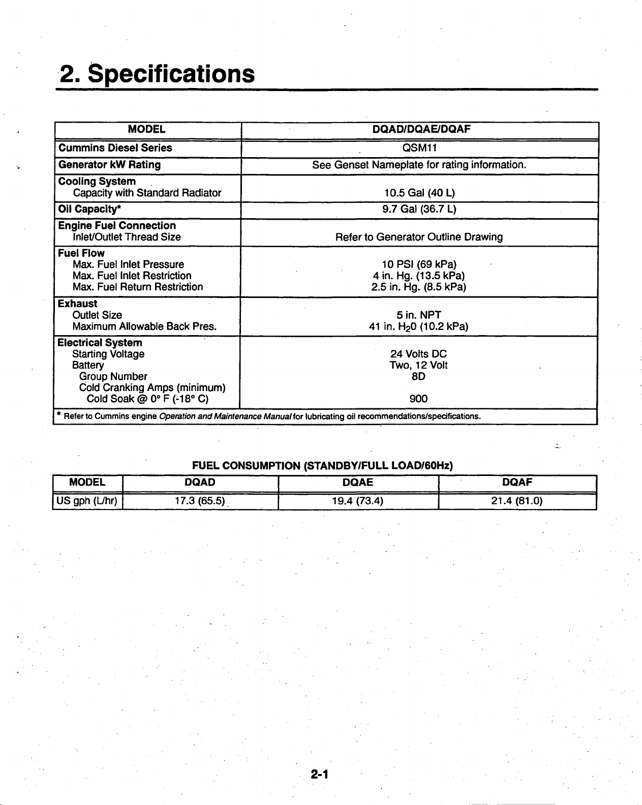
MODEL
Cummins
Generator kW Rating See Genset Nameplate for rating information.
Cooling
Capacity with Standard Radiator
Oil
Capacity*
Engine
Inlet/Outlet Thread Size
Fuel
Max. Fuel Inlet Pressure
Max. Fuel Inlet Restriction
Max. Fuel Return Restriction
Exhaust
Outlet Size
Maximum Allowable Back Pres.
Electrical
Starting Voltage
Battery
* Referto Cummins engine Operation and Maintenance Manual for lubricating oil recommendations/specifications.
Diesel
System
Fuel
Flow
System
Group Number
Cold Cranking Amps (minimum)
Cold Soak@0oF(-18o C)
Series
Connection
Refer to Generator Outline Drawing
DQAD/DQAE/DQAF
QSM11
10.5 Gal (40 L)
9.7 Gal (36.7 L)
10PSI(69kPa)
4 in. Hg. (13.5 kPa)
2.5 in. Hg. (8.5 kPa)
5 in. NPT
41 in. H20(10.2kPa)
24 Volts DC
Two,
12 Volt
8D
900
MODEL
US gph (L/hr)
FUEL
CONSUMPTION
DQAD
17.3 (65.5)
(STANDBY/FULL
DQAE
19.4 (73.4)
LOAD/60Hz)
DQAF
21.4(81.0)
2-1
Page 9

3.
Mounting
the Generator Set
GENERAL
Generator set installations must be engineered so
the generator set will function properly under
pected load
general guide only. Follow the instructions of the
consulting engineer when locating or installing any
components. The complete installation must comply with all local and state building codes, fire ordinances, and other applicable regulations. Consider
these requirements before installation:
Requirements to be considered prior to installation:
• Level mounting surface
• Adequate cooling air
• Adequate fresh induction air
• Discharge of generator set air
• Non-combustible mounting surface.
INCORRECT
PERSONAL
BE
TRAINED AND
PONENT
conditions.
INSTALLATION,
INJURY,
INSTALLATION.
Use these instructions as a
DEATH,
EXPERIENCED
SERVICE
AND/OR EQUIPMENT DAMAGE.
the
ex-
IAWARNING
OR
PARTS
TO
PERFORM
• Discharge of exhaust gases
• Electrical connections
• Accessibility for operation and servicing
• Noise levels
• Vibration isolation
LOCATION
Generator set location is decided mainly by related
systems such as ventilation, wiring, fuel, and exhaust. The set should be located as near as possible to the main power service entrance. Exhaust
must not be able to enter or accumulate around inhabited areas.
Provide a location away from extreme ambient temperatures and protect the generator set from ad-
verse weather conditions.
REPLACEMENT
ELECTRICAL
CAN
SERVICE
AND MECHANICAL COM-
RESULT
PERSONNEL
IN
SEVERE
MUST
DEPENDING
AND
REGULATIONS
BEFORE
POLLUTION
STRUCTION
BEGINNING INSTALLATION OF YOUR
ON YOUR
MAY
CONTROL
PLANS.
LOCATION
REQUIRE
OR AIR QUALITY
AND INTENDED
YOU TO OBTAIN AN AIR QUALITY EMISSIONS PERMIT
IMPORTANT
USE,
GENSET.
AUTHORITIES
3-1
FEDERAL,
BE
SURE
BEFORE
COMPLETING
STATE
TO
OR
LOCAL
CONSULT
YOUR
LAWS
LOCAL
CON-
Page 10
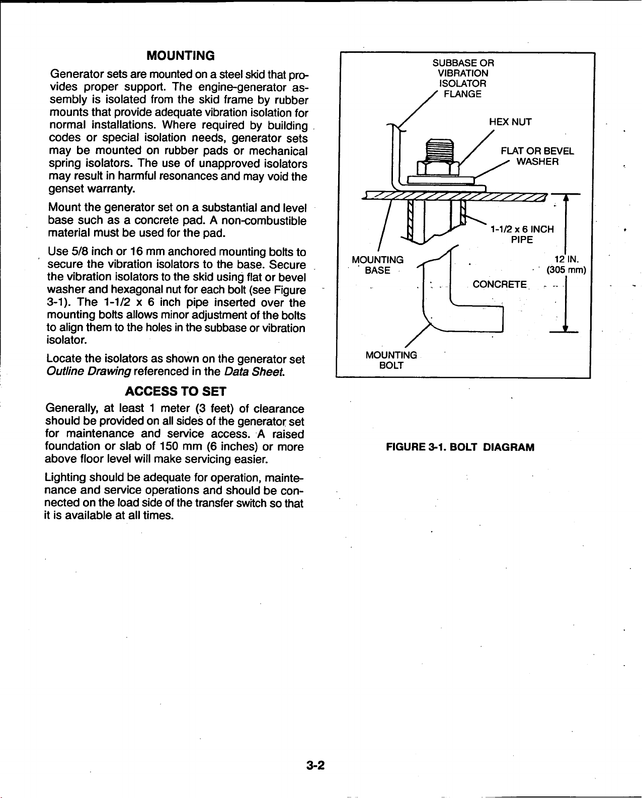
MOUNTING
Generator sets are mounted on a steel
skid
that provides proper support. The engine-generator assembly is isolated from the skid frame by rubber
mounts that provide adequate vibration isolation for
normal installations. Where required by building
codes or special isolation needs, generator sets
may be mounted on rubber pads or mechanical
spring isolators. The use of unapproved isolators
may result in harmful resonances and may void the
genset warranty.
Mount the generator set on a substantial and level
base such as a concrete pad. A non-combustible
material must be used for the pad.
Use 5/8 inch or 16 mm anchored mounting bolts to
secure the vibration isolators to the base. Secure
the vibration isolators to the skid using flat or bevel
washer and hexagonal nut for each bolt (see Figure
3-1). The 1-1/2 x 6 inch pipe inserted over the
mounting bolts allows minor adjustment of the bolts
to align them to the holes
in
the subbase or vibration
isolator.
Locate
Outline Drawing
the
isolators
as
shown
referenced
on the
generator set
in the Data Sheet
MOUNTING
BASE
MOUNTING
BOLT
SUBBASE OR
VIBRATION
ISOLATOR
FLANGE
CONCRETE
HEX NUT
FLAT OR BEVEL
WASHER
1-1/2x6
INCH
PIPE
12 IN.
(305 mm)
ACCESS
TO SET
Generally, at least 1 meter (3 feet) of clearance
should be provided on all sides of the generator set
for maintenance and service access. A raised
foundation or slab of 150 mm (6 inches) or more
above floor level will make servicing easier.
Lighting should be adequate for
nance and service operations and should be
nected on the load side of
the
operation,
mainte-
con-
transfer switch so that
it is available at all times.
FIGURE
3-1.
BOLT DIAGRAM
3-2
Page 11
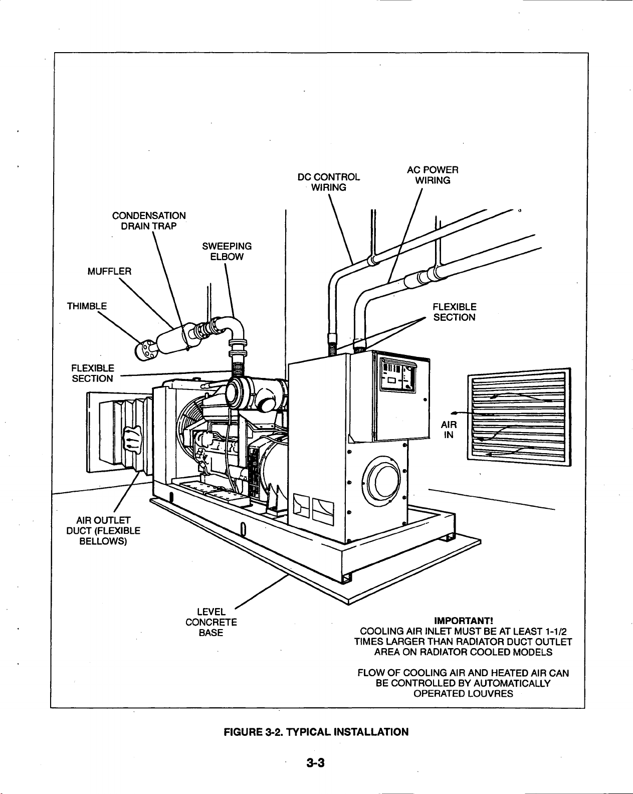
MUFFLER
THIMBLE
FLEXIBLE
SECTION
CONDENSATION
DRAIN TRAP
DC CONTROL
WIRING
AC POWER
WIRING
AIR OUTLET
DUCT (FLEXIBLE
BELLOWS)
LEVEL
CONCRETE
BASE
FIGURE
3-2.
TYPICAL
3-3
IMPORTANT!
COOLING AIR INLET MUST BE AT LEAST 1-1/2
TIMES LARGER THAN RADIATOR DUCT OUTLET
AREA ON RADIATOR COOLED MODELS
FLOW OF COOLING AIR AND HEATED AIR CAN
BE CONTROLLED BY AUTOMATICALLY
OPERATED LOUVRES
INSTALLATION
Page 12
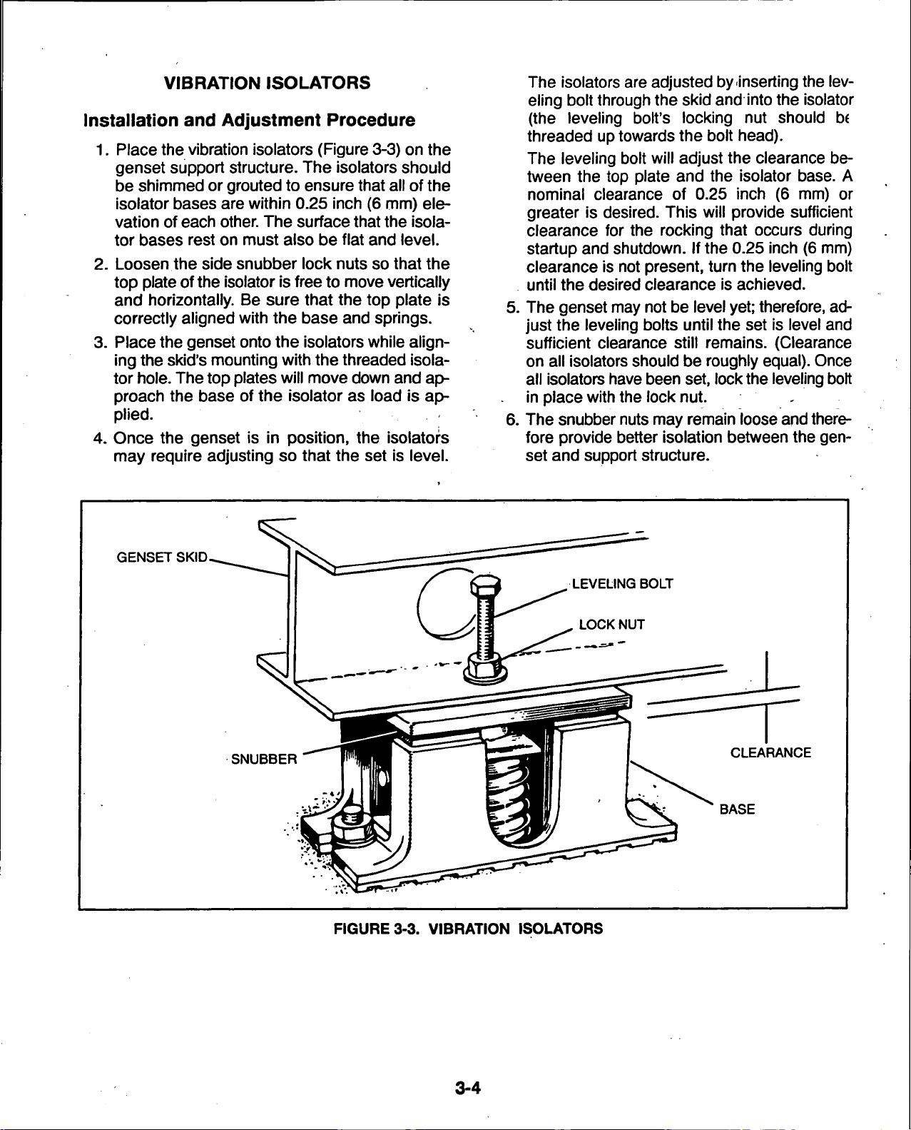
VIBRATION
ISOLATORS
Installation and Adjustment Procedure
1.
Place the vibration isolators (Figure 3-3) on the
genset support structure. The isolators should
be shimmed or grouted to ensure that all of the
isolator bases are within 0.25 inch (6 mm) ele-
vation of each
other.
The surface that the isola-
tor bases rest on must also be flat and level.
2.
Loosen the side snubber lock nuts so that the
top plate ofthe isolator is free to move vertically
and horizontally. Be sure that the top plate is
correctly aligned with the base and springs.
3. Place the genset onto the isolators while aligning the skid's mounting with the threaded isola-
tor
hole.
The top plates will move down and approach the base of the isolator as load is applied.
4.
Once the genset is in position, the isolators
may require adjusting so that the set is level.
The isolators are adjusted by inserting the leveling bolt through the skid and into the isolator
(the leveling bolt's locking nut should be
threaded up towards the bolt head).
The leveling bolt will adjust the clearance be-
tween the top plate and the isolator base. A
nominal clearance of 0.25 inch (6 mm) or
greater is desired. This will provide sufficient
clearance for the rocking that occurs during
startup and shutdown. If the 0.25 inch (6 mm)
clearance is not present, turn the leveling bolt
until the desired clearance is achieved.
5. The genset may not be level
yet;
therefore, adjust the leveling bolts until the set is level and
sufficient clearance still remains. (Clearance
on all isolators should be roughly
all isolators have been set, lock
equal).
the
leveling bolt
in place with the lock nut. -
6. The snubber nuts may remain loose
and
fore provide better isolation between the
set and support structure.
Once
there-
gen-
GENSET SKID.
SNUBBER
FIGURE
3-3. VIBRATION
CLEARANCE
ISOLATORS
3-4
Page 13
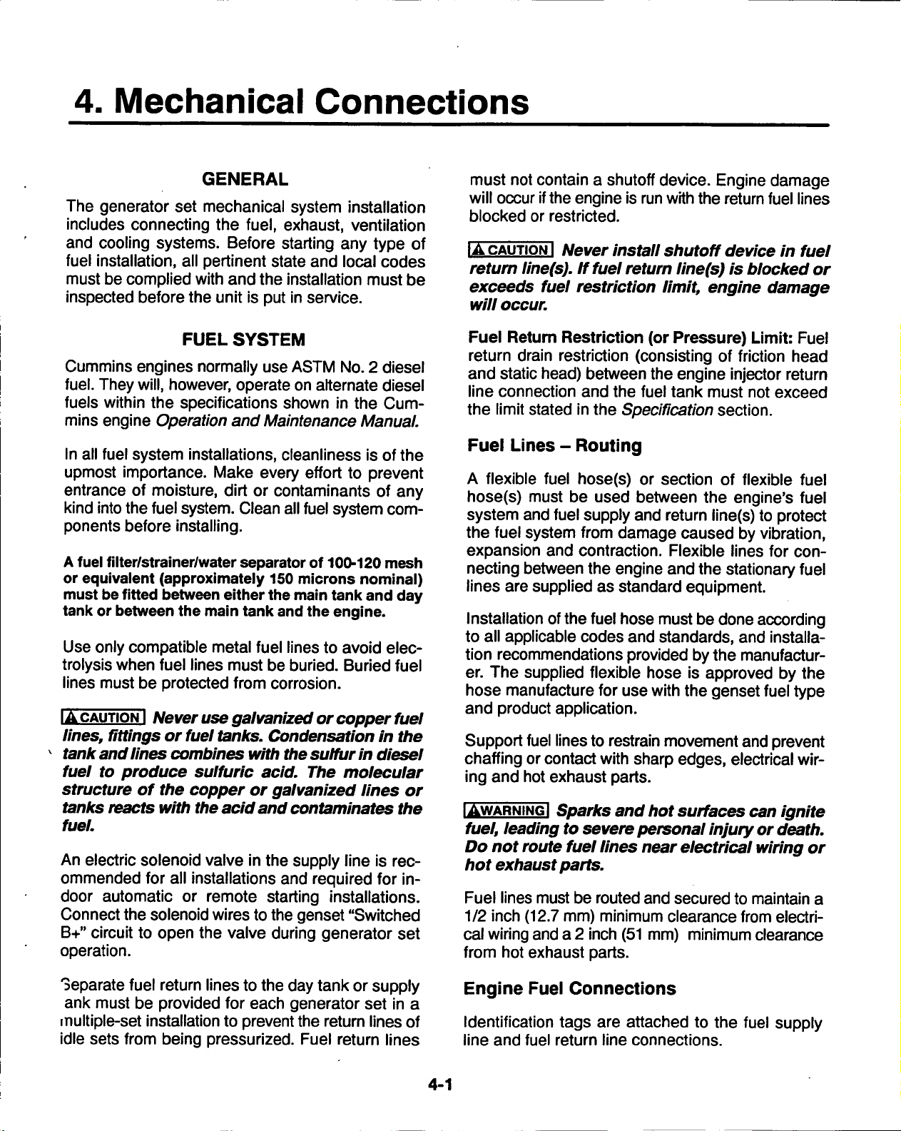
4. Mechanical
Connections
GENERAL
The generator set mechanical system installation
includes connecting the
and cooling systems. Before starting any type of
fuel installation, all pertinent state and local codes
must be complied with and the installation must be
inspected before the unit is put in service.
FUEL
Cummins engines normally use ASTM No. 2 diesel
fuel. They will, however, operate on alternate diesel
fuels within
mins engine Operation and Maintenance Manual.
In all fuel system installations, cleanliness is ofthe
upmost importance. Make every effort to prevent
entrance of moisture, dirt or contaminants of any
kind into the fuel
ponents before installing.
A
fuel filter/strainer/water separator of 100-120 mesh
or equivalent (approximately 150 microns nominal)
must
be
tank or between the main tank
Use only compatible metal fuel lines to avoid elec-
trolysis when fuel lines must be buried. Buried fuel
lines must be protected from corrosion.
IACAUTIONI
lines, fittings
tank and
fuel to produce sulfuric acid. The molecular
structure
tanks reacts with the
fuel.
An electric solenoid valve in the supply line is recommended for all installations and required for indoor automatic or remote starting installations.
Connect the solenoid wires to the genset "Switched
B+"
circuit to open the valve during generator set
operation.
the
specifications shown
system.
fitted between either the main tank and day
Never use galvanized
or
fuel tanks. Condensation
lines combines with the
of the copper or
fuel,
exhaust, ventilation
SYSTEM
in the Cum-
Clean all fuel system com-
and
the engine.
or
copper fuel
sulfur in
galvanized
acid
and contaminates
lines or
in the
diesel
the
must not contain a shutoff
will occur if
blocked or restricted.
IA
retum
exceeds fuel
will
Fuel Retum Restriction (or Pressure) Limit: Fuel
return drain restriction (consisting of friction head
and static head) between the engine injector return
line connection and the fuel tank must not exceed
the limit stated in the Specification section.
Fuel
A flexible fuel hose(s) or section of flexible fuel
hose(s) must be used between the engine's fuel
system and fuel supply and return line(s) to protect
the fuel system from damage caused by vibration,
expansion and contraction. Flexible lines for
necting between the engine and the stationary fuel
lines are supplied as standard equipment.
Installation of
to all applicable codes and standards, and installation recommendations provided by the manufacturer. The supplied flexible hose is approved by the
hose manufacture for use with the genset fuel type
and product application.
Support fuel lines to restrain movement
chaffing or contact with sharp edges, electrical
ing and hot exhaust parts.
IAWARNINGI
fuel,
Do not
hot exhaust parts.
Fuel lines must be routed and secured to maintain a
1/2 inch (12.7 mm) minimum clearance from electrical wiring and a 2 inch
from hot exhaust parts.
CAUTION I
line(s).
occur.
Lines
leading
route
device.
the
engine is
Never
If
fuel return
restriction
- Routing
the
fuel hose must be done according
Sparks
to
severe personal injury
fuel
install
and hot
lines
(51
run
with the return fuel lines
shutoff
limit, engine damage
near
mm) minimum clearance
Engine damage
device
linefs) is
surfaces can
electrical wiring
blocked
and
prevent
or
in fuel
or
con-
wir-
ignite
death.
or
Separate fuel return lines to the day tank or supply
ank must be provided for each generator set in a
multiple-set installation to prevent the return lines of
idle sets from being pressurized. Fuel return lines
Engine
Identification tags are attached to the fuel supply
line and fuel return line connections.
Fuel
Connections
4-1
Page 14
ENGINE
FUEL
PUMP
DAY TANK
FUEL TRANSFER•
PUMP ELECTRIC '
MOTOR DRIVEN
VENTED
FILL CAP
120 MESH FUEL
STRAINER
LARGER OVER-
FLOW LINE
INJECTOR FUEL
RETURN LINE
CONNECT TO
AC OUTPUT
FUELTANK
All models require a fuel return
line from injectors to tank.
VENT LINE
. FILL PIPE
FIGURE 4-1 TYPICAL FUEL SUPPLY INSTALLATION
Supply
Tank
fer tank (referred to as a day tank) and auxiliary
pump will also be required. If an overhead main fuel
Locate the fuel tank as close as possible to the
erator set and within the restriction limitations of the
fuel pump. /
Install a fuel tank that has sufficient capacity to supply the genset operating continuously at full rated
load for the planned period of operation or power
outage. Refer to product Specification Sheet for
fuel consumption data.
gen-
tank is installed, a transfer tank and float valve will
be required to prevent fuel head pressures from be-
ing placed on the fuel system components.
For critical start applications, where generator sets
are paralleled or must satisfy emergency start-time
requirements, it is recommended that a fuel tank or
reservoir be located such that the lowest possible
fuel level is not less than 6 inches (150 mm) above
the fuel pump inlet This will prevent air from accu-
IAWARNINGI Fuel leaks create fire and explosion
hazards which can result in severe personal in-
jury or death. Always use flexible tubing be-
tween engine and fuel supply to avoid line failure and leaks due to vibration. The fuel system
must meet applicable codes.
If the fuel inlet restriction exceeds the defined limit
due to the distance/customer-supplied plumbing
between the genset and the main fuel tank, a trans-
mulating in the fuel line while the set is in standby,
eliminating the period during startup when it has to
be purged.
Fuel Inlet Pressure/Restriction Limit:: Engine
performance and fuel system durability will be compromised ifthe fuel inlet pressure or restriction limits
are not adhered to. Fuel inlet pressure or restriction
must not exceed the limits stated in the Specification section.
4-2
Page 15

Day Tank (If
Used)
Fuel day tanks are used when fuel inlet restriction
limits can not be
met,
or
the
supply tank is overhead
and presents problems of high fuel head pressure
for the fuel inlet and return lines.
Supply Tank Lower Than
lation,
the day tank is installed near the generator
Engine:
With
this instal-
set, below the fuel injection system and within the
fuel inlet restriction limit. Install an auxiliary fuel
pump,
to pump fuel from the supply tank to the day
tank. A float switch in the day tank controls operation of the auxiliary fuel pump.
The supply tank top must
to prevent siphoning from
be
below the
the
fuel
day
tank top
supply to the day
tank.
Provide a return line from the engine injection sys-
tem return connection to the day
tank.
Plumb the re-
turn line to the bottom of day tank as shown in
ure
4-1.
Provide a day tank overflow line to the sup-
Fig-
ply tank in case the float switch fails to shut off the
fuel transfer pump.
IAWARNINGI Spilled fuel presents the hazard of
fire or
sonal injury or
to the supply tank
explosion which can
death.
Provide an overflow line
from
the day tank.
result
in severe per-
Supply Tank Higher Than Engine: Install the day
tank near the generator
set,
but below the fuel injec-
tion system. Use fuel line at least as large as the fuel
pump inlet. The engine fuel return line must enter
the day tank.
Include a shutoff valve in the fuel line between the
fuel supply tank and the day tank to stop fuel flow
when the generator set is off.
IAWARNINGI
and
prevention
Spilled fuel can create environmental hazards. Check local requirements
of
draining
to
sewer and
ground
water.
for
containment
4-3
Page 16

EXHAUST
SYSTEM
Pipe exhaust gases to the outside of any enclosure.
Locate the exhaust outlets away from any air inlets
to avoid gases re-entering the enclosure. Exhaust
installations are subject to various detrimental
conditions such as extreme heat, infrequent operation
and light loads. Regularly inspect the exhaust system both visually and audibly to see that the entire
system remains fume tight and safe for operation.
IAWARNINGI
sult
in
treme
exhaust system.
Inhalation
severe
care
personal
during installation
Terminate
of exhaust
injury or
death.
to
exhaust pipe away
gases
Use ex-
provide
can re-
a tight
from enclosed or sheltered areas, windows,
doors
and
vents.
For indoor installation, the exhaust system must
use sealed joint type fittings, (for example NPT fittings) to provide a tighter exhaust system. Use of
slip type fittings (secured with a muffler clamp) may
allow leakage of exhaust gases into the building.
IAWARNINGI
sult in severe
treme
exhaust
tings for all indoor
Inhalation
personal
care during
system.
of exhaust
injury or
installation
Use
NPT or
installations.
gases
death.
to
provide
can re-
Use ex-
a tight
equivalent type
fit-
Use an approved thimble (Figure 4-2) where exhaust pipes pass through wall or partitions.
Insu-
lated wall/roof thimbles are used where exhaust
pipes pass through a combustible roof or
includes structures, such as wood framing or
wall.
This
insu-
lated steel decking, etc. Uninsulated wall/roof
thimbles are used where exhaust pipes pass
through a non-combustible wall or
roof,
such as
concrete. Refer to NFPA 37, Section 6-3. "Stationary Combustion Engines and Gas Turbines" for ac-
cepted design practices. Build according to the
code requirements in effect at the installation site.
I AWARNING I Hot
and cause severe
routed
through walls.
where exhaust
exhaust
injury
pipes can start a fire
or
Use
death
an
if
improperly
approved thimble
pipes pass through walls
or par-
titions.
IAWARNINGI
sult in severe
use
exhaust heat to warm a room, compartment
Inhalation
personal
of
exhaust gases
injury or
death.
can
re-
Do not
or storage area.
Rain caps are available for
the
discharge
end
of
vertical exhaust pipes. The rain cap clamps onto the
end of the pipe and opens due to exhaust discharge
force from the generator set. When the generator
set is stopped, the rain cap automatically closes,
protecting the exhaust system from
rain,
snow, etc.
Use a section of flexible exhaust pipe between the
engine and remainder of exhaust system. Support
exhaust system to prevent weight from being applied to engine exhaust outlet elbow/turbocharger
connection.
IACAUTIONI
fold can result in
Weight applied
turbocharger damage.
to
the
engine mani-
Sup-
port the muffler and exhaust piping so no
weight or
stress
is
applied
to
engine exhaust el-
bow.
The exhaust system design should meet local code
requirements.
Liability for injury,
pense
cations
due
to the
to
sibility of the
fler
or
performing
mins
haust
Power
system
Generation
death,
use
of unapproved
exhaust
person
system
installing
the modification.
distributor for
parts.
damage,
mufflers
becomes
the
and
warranty
or
modifi-
the
respon-
unapproved
Contact
a Cum-
approved
ex-
muf-
ex-
4-4
Page 17

Avoid sharp bends by using sweeping, long radius
elbows and provide adequate support for muffler
and tailpipe. Pitch a horizontal run of exhaust pipe
DOWNWARD (away from engine) to allow any
moisture condensation to drain away from the engine.
If an exhaust pipe must be turned upward, install a condensation trap at the point where the rise
begins (Figure 4-3).
Shield or insulate exhaust lines if there is danger of
personal contact. Allow at least 12 inches (305 mm)
of clearance if
the
pipes pass close to a combustible
wall or partition. Before installing insulation on ex-
haust system components, check the exhaust sys-
tem for leaks while operating the genset under full
load and correct all leaks.
RAIN
CAP
9 INCH MIN
(230 mm)
DRIP CAP
HOLES IN END
OF INNER
SLEEVE
ROOF
9 INCH MIN
(230 mm)
IAWARNINGI Exhaust
can
cause severe personal injury
direct contact
sulate
exhaust
sonal contact
near other
or
or
combustible materials.
pipes
from
pipes if
when
fire
there
routed
are very hot and
or
death
hazard. Shield
is danger of per-
through
walls or
they
from
or in-
WALL OR PARTITION
FIGURE 4-2.
MOUNTING
\ PITCHED UPWARD, CONSTRUCT
EXHAUST
IF EXHAUST LINE MUST BE
A TRAP AT POINT OF RISE
THIMBLE
4-5
AVOID ^LM
SHARP M
BENDS
^fl DRAIN CONDENSATION
jl TRAP PERIODICALLY
FIGURE
4-3.
CONDENSATION
TRAP
Page 18

VENTILATION
AND
COOLING
Generator sets create considerable heat that must
be removed by proper
ventilation.
Outdoor installations normally rely on natural air circulation but indoor installations need properly sized and
posi-
tioned vents for required airflow.
Vents
and
Ducts
For indoor installations, locate vents so incoming air
passes through the immediate area of the installation before exhausting. Install the air outlet higher
than the air inlet to allow for convection air move-
ment.
Size the vents and ducts so they are large enough to
allow the required flow rate of
air.
The "free
area"
of
ducts must be as large as the exposed area of the
radiator. Refer to the model-specific Specification
Sheet for the airflow requirements and allowed
air-
flow restriction.
Wind will restrict free airflow if it blows directly into
the air outlet vent. Locate the outlet vent so the ef-
fects of wind are eliminated. See Figure 4-4.
PREVAILING WINDS PREVAILING WINDS
FIGURE
4-4.
WIND
BARRIER
4-6
Page 19

Dampers
Dampers or louvres protect the genset and equipment room from the outside environment. Their
operation of opening and closing should be
trolled by operation of the genset.
In cooler climates movable or discharge dampers
are
used.
These dampers allow
lated back
equipment room to be heated while the genset engine is still
Radiator Set Requirements
Radiator set cooling air is drawn past the control
end of
the radiator (Figure
the rear of
to 2 times larger than the radiator area.
to
the equipment
cold,
increasing the engine efficiency.
the
set by a pusher
the
set.
4-5).
Locate the air inlet to the to
Make the inlet vent opening 1-1/2
the
air
to
room.
fan
This enables the
that blows air through
con-
be recircu-
Locate the cooling air outlet directly in front of
diator and as close as possible. The outlet opening
must be at least as large as the radiator area.
Length and shape of the air outlet duct should offer
minimum restriction to airflow.
Attach a canvas or sheet metal duct to the flange
and the air outlet opening using screws and nuts so
duct can be removed for maintenance purposes.
The duct prevents circulation of heated air. Before
installing the duct, remove the radiator core guard.
Standard Radiator Cooling uses a set mounted
radiator and engine pusher fan to cool the engine.
Air travels from the generator end of the set, across
the engine and out through the radiator. An integral
discharge duct adapter flange surrounds the radiator grille.
Engine
Coolant
Heater
(Optional)
the
ra-
Louvers and screens over air inlet and outlet openings restrict air flow
A louver assembly with narrow
tends to be more restrictive than one with wide
vanes.
ver or screen manufacturer should be used.
The effective open
and
INLET AIR
DAMPER
COOL AIR
vary widely in performance.
vanes,
area
specified by the
for example,
lou-
THERMOSTATIC AIR
An optional engine coolant heater is available to
keep the engine warm for starting under adverse
weather conditions. Connect the heater to a power
source that will be energized when the engine is
NOT running.
RECIRCULATING
DAMPER *
WIND/NOISE
BARRIER
I
HOT AIR
)
Louvers should close when room
ambient is above 60° F (16° C)
FIGURE 4-5. TYPICAL RADIATOR SET INSTALLATION
RADIATOR
4-7
FLEXIBLE DUCT
CONNECTOR
DISTANCE SHOULD NOT
BE LESS THAN HEIGHT
OF RADIATOR
Page 20

5. DC Control
Wiring
CONTROL
The generator set accessory box (Figure 5-1),
which is located on the backside of
ing,
contains connection points for remote control
and monitor options.
IACAUTIONI
for all
Box.
Solid
vibration.
TB1
Customer monitor/control connections are attached to terminal block
equipment such as sensing devices used to monitor
genset operation, remote start/stop switches,
trol box heater, battery charger and etc. are attached to
tions diagram in Section 9.
TBI
Wiring
a
separate metal conduit from
to avoid inducing currents that could cause
problems within
Stranded copper wire must
customer connections
copper wire
REMOTE
CONNECTIONS
TB1.
Refer to PCC Customer Connec-
Always
the
WIRING
the
control hous-
be
to
the
Accessory
may
break
MONITOR/CONTROL
TB1
(Figure 5-1). Optional
run
control circuit wiring
control.
due to
AC
power cables
genset
con-
used
in
Digital Connections: Connection points, other
then relayed outputs, network, switched B+ and B+
are considered digital connections to terminal strip
TB1.
The type/gauge wire to use for these connec-
tions are:
• Less than 1000 feet (305m), use 20 gauge
stranded copper wire.
• 1000 to 2000 feet (305 to
stranded copper wire.
Relay Connections:
vices that can be attached to the relay outputs of
TB1,
the electrical contractor must determine the
gauge of the stranded copper wire that is used at
this installation site. Refer to Customer Connections diagram in Section 9 for the relay
specifications.
Network Connections: Refer to 900-0366 Power-
Command Network Installation and Operation
manual for the type/gauge wire to use for
nections.
Switched B+: (Fused at 10 amps.) Same as Relay
Connection description.
B+:
(Fused at 20 amps.) Same as Relay Connec-
tion description.
Due
610m),
to the wide variety of de-
use 18 gauge
these
con-
5-1
Page 21

OPTIONAL
COMMON ALARM
RELAY K14
TBI-1
OPTIONAL RUN
RELAYS
K11,
K13
K12 &
TBI-62
FIGURE
5-1. ACCESSORY BOX
5-2
Page 22

RUN
RELAYS
The optional run relays are rail mounted inside the
accessory box (Figure 5-1). The rail mount allows
you to easily remove and replace the snap-on re-
lays.
The generator set can be equipped with one,
two or three run relays.
The three-pole, double-throw run relays (Figure
5-2) are
used
to control auxiliary equipment such as
(Kl
1,
K12, 13)
K11,K12, K13
K11,K12, K13
fans,
pumps and motorized air dampers. The run
relays are energized when the generator set control
receives a start signal.
The contacts are rated:
• 10 amps at 28 VDC or 120 VAC, 80%PF
• 6 amps at 240
• 3 amps at 480/600 VAC, 80%PF
I
7
4
2
8
5
CUSTOMER
CONNECTIONS
VAC,
80%PF
A40-TB1-8 _
(SWITCHED B+)
RUN RELAY
®
5
ffl
©
I®
K11,
K12, K13
K11
©
©
© © ©
3
9
6
NO
NC
CO
"- A40-TB1-12
COM (B-)
RUN RELAY
©
©
5
©
©
3-
K12
©
©
©
© ©
NO
NC
K13
RUN RELAY
©
©
©
©
r-®
© ©
©
©
©
NO
NC
FIGURE
5-2. OPTIONAL
RUN RELAYS
5-3
(Kll,
K12,
K13)
Page 23

ALARM
RELAY
(K14)
The optional alarm relay is rail mounted inside the
accessory box (Figure 5-1). The rail mount allows
you to easily remove and replace the snap-on relay.
The three-pole, double-throw alarm relay (Figure
5-3) is often used to energize warning devices such
as audible alarms. Any generator set warning or
shutdown will energize the alarm relay.
The contacts are rated:
• 10 amps at 28 VDC or 120 VAC, 80%PF
• 6 amps at 240 VAC, 80%PF
• 3 amps at 480/600 VAC, 80%PF
A40-TB1-11
(GND)
A40-TB1-31 —
(COMMON ALARM)
K14
K14
K14
JUMPER WIRE
REQUIRED FOR K14
RELAY OPTION
I
A40-TB1-1
(B+)
7
4
2
8
5
3
9
6
COMMON ALARM
CUSTOMER,
CONNECTIONS
K14
©
©
3
"51
9. lei
2
©
©
©
NO
©
NC
©
C011
©
- A40-TB1-30
COM (COMMON ALARM)
©
FIGURE
5-3.
OPTIONAL
ALARM
5-4
RELAY
(K14)
Page 24

6. AC
This section provides the procedure that is used to
connect the AC electrical system of the genset.
IACAUTIONI Before disconnecting battery
cablefs),
wait at least 30
may be affected (e.g., engine dying or hard
starting) if battery
the 30 second
nel may be
Electrical
GENERAL
press
the Emergency Stop button
seconds. Engine performance
cablefs)
waiting period. Service
required
to
correct fault.
is
removed
Connections
and
during
person-
2.
Press the Emergency Stop button and wait at
least 30 seconds before completing Step 3.
3. Turn off or remove AC power from the battery
charger.
4.
Remove the negative (-) battery cable from the
generator set starting battery.
Connecting the genset AC electrical system in-
volves:
IAWARNINGI
can
cause
ing at battery
equipment, name,
nite battery gas. Do not smoke, or switch
trouble light ON
static
teries by first
face.
Ventilate
battery—Wear goggles—Stop
connect charger before
cables—Disconnect negative
reconnect
IACAUTIONI Disconnect battery
source before
Otherwise, disconnecting cables
voltage spikes damaging to DC control circuits
of
the
IAWARNINGI
set
can
Prevent accidental starting by
the negative
Before making any AC electrical connections, make
certain the generator set cannot be accidentally
started as follows:
1.
Move the Run/Off/Auto switch on the control
panel to the OFF
Ignition
severe
terminals,
electricity from
touching a grounded
battery
last.
set
Accidental starting
cause
severe personal injury
(-)
of
personal injury
pilot
or OFF near
area before working on
disconnecting
cable from the battery terminal.
position.
explosive battery gases
or
light
lights
body
disconnecting
switch
and
battery. Discharge
before touching bat-
genset and dis-
(-)
cable
charger from
battery cables.
of
disconnecting
death.
sparks can ig-
metal sur-
can result in
the generator
or
Arc-
or other
or near
battery
first
and
AC
death.
• Installation of transfer switch
• Generator output voltage selection
• Load cable connection
• Standard and optional AC equipment connections
(e.g.,
control box heater, coolant heater,
etc.
Local regulations often require that wiring connections be made by a licensed electrician, and that the
installation be inspected and approved before operation.
etc. must conform to the requirements of electrical
codes in effect at the installation
IAWARNINGI Improper
electrocution, resulting
ry or
age.
Before starting the genset, check to make sure that
all electrical connections are secure, and that all
wiring
panels that have been removed during installation.
Check that the load cables from the genset are
properly
IAWARNINGI Backfeed to utility system can
cause electrocution or property damage. Do
not connect to any building electrical system
except through an approved device and after
building main
All connections, wire
death
is
and/or property and
complete.
connected.
Replace and secure any access
switch is opened.
sizes,
wiring
in
materials
site.
can
cause
severe personal inju-
equipment dam-
used,
a fire or
6-1
Page 25

TRANSFER
SWITCH
If the installation is for standby service, a transfer
switch must be used for switching the load from the
normal power source to the genset (see Figure 6-1).
Follow the installation instructions provided with the
transfer switch when connecting the load and
trol wiring.
con-
NORMAL
SOURCE
FIGURE
6-1.
LOAD
TYPICAL
FUNCTION
LOAD
GENSET
TRANSFER
•
1
i
i .... J
6-2
Page 26

AC
WIRING
Generator
Voltage
Connections
The available generator output voltages and maxi-
mum current ratings are specified on the generator
set nameplate. Line-to-neutral voltage is always the
lower voltage shown and line-to-line voltage is the
higher rating.
All loads are connected to the generator by bolting
stranded load wires to the appropriate terminals on
the generator reconnection terminal block or circuit
breaker lugs. The terminals are stamped U, V, W
and N to indicate the line and neutral connections.
(Reference:
L3;
and N with
Load
Balancing
U,
V,
and
W correspond
LO
respectively).
with
Ll, L2 and
These generators can be configured to the nameplate voltages as shown on the Reconnection Diagram located on the side access cover of
housing.
Many of the voltages listed will require re-
the
control
configuration of the generator output leads on the
connection terminal block. This reconfiguration
must only be done by service personnel that are
trained and experienced to perform electrical instal-
lation.
The generator set was adjusted to produce a
specified voltage during production verification testing prior to shipment. The installer must always
check the stator lead terminal block connections
and perform any necessary reconnect to obtain the
voltage required.
Some generator sets are capable of producing a
wide range of voltages and connection configurations,
others have specific limited capabilities. Refer to wiring diagram and generator voltages (from
the nameplate) when reviewing the voltage connection information and use the wiring diagram supplied with your generator set when actually performing load connections.
Reconfiguring generator sets to
higher
ity of
age the
rent,
Consult with your
voltages can exceed the voltage capabil-
the specific generator windings
generator
rendering
and also decrease line cur-
line circuit breakers too large.
and
dam-
distributor before performing
reconnection for a different voltage.
IACAUTIONI Reconfiguring generator sets to
lower voltages can reduce generator set ratings,
and
also increase
line
current,
rendering
line circuit breakers too small. Consult with
your distributor before performing reconnec-
tion
fora
different voltage.
Load
Connections
Flexible conduit and stranded conductors must be
used for connections to take up movement of the
generator set.
When connecting loads to the generator set,
ance the loads so the current flow
minal (Ll, L2 and L3) is about the
from
same.
each line
This is es-
bal-
ter-
pecially important if both single phase and three
phase loads are
connected.
Any combination of
single phase and three phase loading can be used as
long as each line current is about the same, within
10 percent of median value and no line current ex-
ceeds the nameplate rating of the generator. Check
the current flow from each line after connections by
observing the control panel ammeter.
Current
Current transformers (CT's) are required on
Transformers
gensets that contain AC meters. The CT's must be
installed as noted in the following CT Installation
Requirements.
Refer to the Reconnection Diagram to identify the
output leads/phase that must be routed through
each CT, and also appropriate transformer post
selection for meter sensing
are labeled
CT21,
CT22 and CT23 on the recon-
leads.
The transformers
nection wiring diagram. (The Reconnection Diagram is located on the upper side cover of the
con-
trol housing.)
CT
Installation Requirements:
A. The CT has a dot
facing toward the generator (conventional
rent flowing into the
on
one
side.
This dot must be
dot).
A dot is also used to
cur-
indicate pin 1 of the CT.
B. CT21 - U load leads (A phase),
CT22 - V load leads (B phase)
CT23 - W load leads (C phase)
C. Route the appropriate load wires through each
CT.
D. The CT's have dual secondaries (3 pins). The
CT secondary wire marked 1 is connected to
pin 1 of the
is connected to
CT.
CT secondary wire marked 2/3
pin
2 for high voltage gensets or
to pin 3 for low voltage gensets. (Refer to Reconnection Diagram.)
6-3
Page 27

Grounding
The following is a brief description of system and
equipment grounding of permanently installed AC
generators within a facility wiring system. It is
important to follow the requirements of the local
electrical code.
Figure 6-2 illustrates typical system grounding for a
3-pole and a 4-pole automatic transfer switch
(ATS).
neutral is connected to the ATS and is NOT bonded
to ground at the generator. In the 4-pole ATS system,
ing jumper are used to connect the generator
tral to ground. In some installations, a CT may be
required for ground fault monitoring (refer to Figure
6-2 for CT location).
In the 3-pole ATS, note that the generator
a grounding electrode conductor and a bond-
neu-
Make sure the genset is grounded to earth in one
location only. On generators without a circuit break-
er, ground to the point indicated on the top of the
generator. On gensets
ground lug provided in the circuit breaker box.
IAWARNINGI Electric current can cause severe
personal
ing must be done
that could become energized under
conditions
Typical requirements for bonding and grounding
are given in the National Electrical Code, Article
250.
to the requirements of the electrical codes in effect
at the installation site.
injury
must be
All connections, wire sizes, etc. must conform
with
circuit breakers, use the
or
death. Bonding
properly.
properly grounded.
All metallic parts
and
ground-
abnormal
TO UTILITY
SERVICE
30
N
TO UTILITY
SERVICE
SERVICE
r
30
N
L --X —L..
SERVICE ENTRANCE
r
-O O-
r-ob-
L
___r—1_.
1
ENTRANCE
4-POLE AUTOMATIC
TRANSFER SWITCH
3-POLE
TRANSFER SWITCH
AUTOMATIC
45
IS
4 WIRES & GROUND
TO LOAD
GENERATOR
4 WIRES & GROUND
TO LOAD
GENERATOR SET
SET
BONDING
.JUMPER
CT LOCATION IF
REQUIRED FOR
GFI MONITORING
GROUNDING
ELECTRODE
CONDUCTOR
FIGURE
6-2.
TYPICAL
SYSTEM
GROUNDING ONE-LINE DIAGRAMS
6-4
Page 28

CONTROL
HEATER
(OPTIONAL)
A control heater (Figure 6-3) provides a means of
humidity /temperature control of the control box in-
TO ACCESSORY BOX
A40-TB1-36 & 37
(PCC CONTROL)
terior.
It protects the components when the genera-
tor set is subjected to varying ambient air conditions
during extended periods of non-use.
nn
k
-ELJ
lur =.j
HEATER
RGURE
BOTTOM VIEW OF
CONTROL BOX
6-3. OPTIONAL
CONTROL
HEATER
6-5
Page 29

COOLANT
HEATER
The coolant heater keeps engine coolant warm
when the engine is shut down. It heats and circulates the coolant within the engine. This reduces
startup time and lessens engine wear caused by
cold starts. It is electrically operated and thermostatically controlled.
IACAUTIONI
TTie coolant
heater
must
not be operated while the cooling system is empty or
damage
to
the
heater will
occur.
Figure 6-4 shows a typical coolant heater. Connect
the heater to a source of power that
will
be
on
during
the time the engine is not running. Be sure the sup-
ply voltage and circuit amperage is correct for the
heater element rating.
Refer to the electrical diagram located inside
the
AC
electrical connection box cover (Figure 6-4) for
coolant heater power connections/voltage selec-
tions.
A
battery
charge.
rent
The
when
charger
heater
the
heater(s)
is
required to prevent
control
relay
draws
is
off. The heater
battery
83
mA
is
off
dis-
of
cur-
when
the engine has reached the proper temperature or
the engine
IACAUTIONI DO not connect AC power to the
heater
will
run continuously without
overheat and
is
running.
before connecting
damage
heater.
battery
DC power
cables. Heater
and can
THERMOSTAT
COOLANT
FLOW
AC ELECTRICAL CONNECTION
BOX (ELECTRICAL DIAGRAM
INSIDE COVER)
DC CONTROL
LINE
DRAIN
AC POWER
LINE
FIGURE
6-4.
TYPICAL
6-6
COOLANT
HEATER
Page 30

GENERATOR
A generator heater(s) is
HEATER
used
to help keep the
gen-
erator free of condensation when the generator set
is not running. During cool and humid conditions,
condensation can form within a generator, creating
flashing and a shock hazard.
Figure 6-5 illustrates the installation of two heater
elements. Connect the heater(s) terminals to a
source of power that will be on during the time the
engine is not running. Be sure the supply voltage
and circuit amperage is correct for the heater ele-
ment rating.
IAWARNINGI
tor increases the
electrical
damage
not
use a generator which
Water
possibiUty
shock,
which can cause equipment
and severe
out.
or
moisture inside
of flashing and
personal injury
is not dry
a genera-
or
death.
inside
and
HEATER
Do
LEADS
\
n
1 3
HEATER
FIGURE
TERMINAL
6-5.
TYPICAL
BOX
HEATER
TERMINAL.
BLOCK
GENERATOR
HEATER
6-7
LEADS
TOTAUHATT8
HEATER
HEATERS
VOLT/WATTS
-
LABEL
INSTALLATION
3
Page 31

FUEL
TRANSFER
PUMP
A fuel transfer pump and control are available when
a sub-base or in-skid day tank are
automatic control operates the fuel pump to
provided.
main-
The
tain a reservoir of fuel in the day tank.
IAWARNINGI Diesel fuel is highly
Improper installation
age of
property if
lation and
large quantities
the
fuel
service must
and experienced
the
applicable codes.
of
this
of fuel and
is
accidentally
be
persons
performed
in accordance with
combustible.
kit
can
lead
loss
ignited. Instal-
by
to
spill-
of
life
trained
anc
Do not smoke near fuel and keep flames,
sparks,
ment, and other
pilot
lights, arcing switches
sources
of
and
equip-
ignition well away.
CONTROL
FLEXIBLE FUEL
RETURN LINE
FLEXIBLE FUEL
SUPPLY LINE
FUEL PUMP
AND MOTOR
FLOAT SWITCH
ASSEMBLY
FIGURE
6-6.
TYPICAL
DAY
TANK
IN-SKID DAY TANK INSTALLATION
FUEL
GAUGE
6-8
FUEL FILL
CAP
Page 32

Fuel Pump Control
The control
VAC.
The control is set up at the factory for connec-
can be
AC
Connections
powered
by
120 VAC
tion to 240 VAC.
1.
To
convert
the day
tank controller from
VAC to 120 VAC, perform the following steps.
A.
Remove the two jumpers between termi-
nals
TB1-6 and TB1-7 in the control box
and connect
TBI-5
and TB1-6 and the other between
terminals TBI-7 and
one
between terminals
TBI-8.
,
or 240
240
2.
To
convert
the day
tank controller from
VAC to 240 VAC, perform the following steps.
A.
Remove
TBI-5
in
the
jumpers
the
jumpers between terminals
and
TBI-6,
control
and TB1-7 and TB1-8
box and
connect
between terminals TBI-6
the two
TBI-7.
B. Move selector switch SI
03
on the control
PCB to the down position for 240 VAC.
C.
If
the control is equipped with a transformer, remove the jumpers between terminals
H1 and H3, and H2 and H4 and connect
the two jumpers between H2 and H3.
120
and
B. Move selector switch S103 on the control
PCB to the up position
C.
If the
control
is
equipped with a trans-
for
120V.
former, remove the two jumpers between
terminals H2 and H3 and connect one between
HI
and H3 and the other between
H2 and H4.
AC
(240V)
EARTH
NEUTRAL
AC
GND
(I20V)-
(I20/240V)
-
I
2 3 4 5 6 7 8
3 Attach a tag
supply voltage.
4 Terminals TBI-8 and TBI-5 are available
connection
shutoff valve rated
The voltage rating
spond with
See Item 2 above.
PI03-GND
PI
03-4
PI03-WHITE
PI
03-3
PI
03-I
9I0II I2I3I4I5I6I7I8I9
00
T
0
to
the control
of a
120
not
of the
the
voltage utilized
20 2I
00
box
indicating
or
240 VAC electric fuel
more than
0.5
amps.
valve must corre-
for
the pump.
-SI
+
USED
-GND
W/O
TRANSFORMER
the
for
J5
oooooooooo
J6
(ooooooooooooo
J3
o
r°°)
FIGURE
6-7.
FUEL
PUMP
PCB
ASSY-DAYTANK 300-3464
CONTROL
6-9
o
CD
TERMINAL
o
to
J4
BOARD
Page 33

GROUND
The optional Ground Fault Relay (GFR) (Figure
6-8) is typically located behind the lower control
housing grille. The ground fault relay continuously
monitors the neutral to ground connection and
vates a fault alarm when the connection is broken.
During genset operation, the relay continuously
monitors the line to neutral and activates a fault
alarm when a ground fault is sensed.
FAULT
(OPTIONAL)
ALARM
RELAY
acti-
After the installation of the genset is complete, perform the following procedure to test the operation of
the ground fault relay.
A. Verify that the N-G Fault Indicator on the
GFR is not lit. If lit, it indicates that the
bonding jumper circuit (neutral to ground)
is
open.
jumper, a bonding jumper must be
installed at the facility service entrance.
If genset does not require bonding
The relay alarm contacts are typically connected to
the genset control to provide a "Ground Fault
Alarm"
A control reset will clear
and will also reset the ground fault relay.
The relay has a time delay setting of zero to one second and a current setting of 5 to 1200 amperes.
Adjust the Current and the Time Delay controls on
the ground fault relay to the customers specifications.
indication.
the
fault at the control panel
A. Move the control switch to the Run
tion.
B. Press the TEST switch on the ground fault
relay.
C. Verify that the control panel warning mes-
* sage is displayed and the Fault Indicator
(>l)
on the GFR is lit.
D. Reset the control panel fault (this will also
reset the ground fault relay).
posi-
6-10
Page 34

CONTROL
HOUSING
GROUND FAULT
RELAY
ASSEMBLY
GRILLE
TEST BUTTON
FAULT
INDICATORS
>l
(OVER CURRENT)
N-G
(OPEN CIRCUIT)
FIGURE6-8.
ON INDICATOR
0-S 4-50 8-&00
1
• 10 5 • IOO 9 - 1200
2 • 20 6 3
• 23 7 =
GROUND
200
300
FAULT
RESET BUTTON
(N.U.,
TO AUTO RESET)
TIME DELAY CONTROL
CURRENT CONTROL
ALARM
RELAY
FACTORY SET
6-11
Page 35

7.
Prestart
Preparation
GENERAL
Before attempting
set, be sure to complete the Installation Checklist in
Section
IACAUTIONI Before disconnecting battery
cablefs),
wait at least 30
may be affected (e.g., engine dying or hard
starting) if battery
the 30 second
nel may be
IAWARNINGI Ignition of
can
tery
flame,
gas.
OFF near
from body before touching batteries by first
touching a grounded metal surface.
Ventilate
battery—Wear goggles—Stop
connect charger
cables—Disconnect negative
reconnect last.
8.
PCC
POWER
press
required
cause severe personal injury. Arcing
terminals, light switch
pilot
lights
Do
not
smoke,
battery.
battery
the
initial start
ON /
STANDBY
the
Emergency Stop button
seconds.
cablefs)
waiting period.
and
or
Discharge static electricity
area before working
before disconnecting
Engine performance
is removed during
to
correct fault.
explosive
or other
sparks
switch trouble light
of
MODE
Service person-
battery
equipment,
can
ignite battery
genset and dis-
f-)
cable first and
the
generator
and
gases
at bat-
ON
on
or near
battery
IACAUTIONI
source before disconnecting battery cables.
Otherwise, disconnecting
voltage spikes damaging
of
IAWARNINGI
set
Prevent accidental starting by disconnecting
the
Before opening the PCC control cabinet to make
the following Power On/Standby Mode
remove the negative (-) battery cable(s) from the
generator set starting battery as follows:
or
Disconnect battery charger from
cables can result in
to DC
the
set.
Accidental starting
can
cause
negative
1.
Move the Run/Off/Auto switch on the control
panel to the OFF
2.
Press the Emergency Stop button and wait at
least 30 seconds before completing Step 3.
3. Turn off or remove AC power from the battery
charger.
4.
Remove the negative (-) battery cable from the
generator set starting battery.
severe
(-)
cable
personal injury or death.
from
position.
control circuits
of
the generator
the battery terminal.
selection,
AC
7-1
Page 36

Selecting
IACAUTIONI
circuit
wear a grounding
Power On or Standby
Mode
Electrostatic discharge will damage
boards. To prevent this damage,
always
wrist strap when working
in-
side control box.
Set the Power On / Standby Mode switch (S5 in
Fig-
ure 7-1) to the desired position.
Power On Mode: Slide the switch to the left to se-
lect the Power On (awake) mode. It is recommended that switch
S5
be left
in
the Power
On
mode
in all applications, except those where battery
charging is not available.
The PCC will initialize the operating software and
permit operation of the menu display panel. Power
will stay on until the switch is reset to the Standby
Mode.
Standby Mode: Slide the switch to the right to select the Standby (sleep) Mode. In this mode, the
PCC operating software will be initiated by:
• moving the Run/Off/Auto switch to the Run
position,
• pressing the Self Test button,
• a remote start input signal (genset in Auto
mode),
or
• any one of several "wake-up" signals from external switches.
With the switch set to Standby mode, pressing the
Self Test button will allow you to activate and view
the menu displays without starting the generator
set. If no menu selections are made, a software
tim-
er will shut down the power after 30 seconds.
When left in the Standby Mode, and a "Warning"
signal is sensed by the PCC (for example, low
engine temp), the control will wake up and display
the warning message. The control will remain active
until the warning condition is corrected and the Re-
set button is pressed to clear the warning message.
DISPLAY
(A35)
BOARD
PCC
g,
POWER
MODE
SWITCH
\
LA
ON /
STANDBY
ENGINE
(S5)
DIGITAL
ANALOG
INTERFACE
(A31) (A34)
BOARD
(A32)
BOARD
(A33)
CUSTOMER
INTERFACE
FIGURE
7-1.
CABINET
INTERIOR (PCC 3100)
7-2
Page 37

ELECTRICAL
SYSTEM
Verify all electrical connections are secure and all
wiring is complete and inspected. Replace and secure any access panels that may have been re-
moved during installation.
Battery
IAWARNINGI
set
Make sure that the
control panel is set to the Off
connecting
Starting,
ing
Connections
can
Accidental starting
cause
severe
personal
Run/Off/Auto switch
the
battery
cables.
of
the generator
injury
or
death.
on the
position
before
the unit requires 24 volt battery current, us-
two 12 volt batteries (see Specification section).
Connect the batteries in series (negative post of first
battery to the positive post of
the
second battery) as
shown in Figure 7-2.
Service the batteries as necessary. If an automatic
transfer switch is installed without a built-in charge
circuit, connect a separate battery charger. A battery charger is required when the PowerCommand
control is set to the Power On (awake) mode.
IAWARNINGI Ignition of
can cause
severe personal injury.
explosive
battery gases
Always connect negative (-) battery cable last to prevent
arcing.
IAWARNINGI
ing on or near
nals,
light switch
lot
lights
not
smoke,
near
battery.
body
before touching batteries
a
grounded
Ventilate
battery.
and
sparks
battery area before work-
Arcing at battery termi-
or
other equipment, flame,
can
ignite battery gas. Do
or switch trouble light ON or OFF
Discharge static electricity from
by
first
touching
metal
surface.
pi-
POSITIVE
FIGURE 7-2. GENSET BATTERY
NEGATIVE
TWO, 12
BATTERIES
VOLT
CONNECTIONS
7-3
Page 38

PCC
OPTIONS
All generator set configuration options are set at the
factory except for site related options,
Stop Time Delays, Cycle Crank, Customer Fault 1
and 2, etc..
Adjustment of these options are divided into two
categories within the menu driven system. These
two categories are Adjust and Setup/Calibrate.
The Setup/Calibrate submenus are intended for
qualified service personnel only and require a password to modify these submenus. The Adjust submenus are intended for service personnel and site
personnel.
The Adjust submenus allow site personnel to
brate the generator set voltage/frequency, and
start/stop time delays. For the prestart checks, ad-
justment of only the start/stop delays is required.
Adjust
To adjust the start and stop delays, press the button
next to the word "ADJUST' in the Main Menu.
ure 7-3 shows a block representation of the ADJUST menu. After you press the button next to the
word "ADJUST' in the display, the VOLTAGE submenu will appear.
As shown in the diagram, the ADJUST menu has
four submenus, including a save/exit procedure. To
move through the VOLTAGE and FREQUENCY
submenus, press the button next to
play the STOP DELAY submenu.
Menu
PRESTART
CHECKS
(e.g.,
Start/
cali-
Fig-
the"»'
to dis-
START DELAY
to remote starting in the Auto mode. Use the buttons
next to the "ff" and'T symbols to set the start delay.
The start delay adjustment range is 0 to 300 sec-
onds.
STOP DELAY submenu: This delay applies only
to remote stopping in the Auto mode. From the
START DELAY submenu, press the button next to
the"»"
submenu.
symbols to set the stop delay. The stop delay adjustment range is 0 to 600 seconds.
SAVE/EXIT submenu: From the STOP DELAY
'submenu,
display to move to the SAVE/EXIT submenu. Select
SAVE to save your changes. At the CHANGES
SAVED submenu, select EXIT to return to the Main
menu.
If you select
after shutdown, and will be in effect when the set is
restarted.
adjustments will remain in effect until the genset is
shut down and return to the previous settings when
the set is restarted.
in the display to move to the STOP DELAY
Use the buttons next to the "tt" and
press the button next to the "»"' in the
If you select EXIT without saving first, the
submenu:
SAVE,
This delay applies only
the adjustments will be retained
7-4
Page 39

I
ADJUST
MENU
•<
ENGINE
ADJUST
•<
•<
ft
VOLTAGE
•<
11
»
•<
tt
•<
•<
•<
•<
•<
FREQUENCY
tt
START
Ji
SEC >>
tt
STOP
U
SEC >>
SAVE
EXIT
DELAY
DELAY
GEN
>>
>>
>•
>•
•
•
•
CHANGES
EXIT
SAVED
>>
•
>U
• <
u<
ENGINE
ADJUST
GEN >•
>> >•
•<
•<
•<
SAVE
EXIT
SAVE
EXIT
•
j
>>
>>
•
>IJ
•
:
•
•<
u<
•<
u<
CHANGES
EXIT
>>
ENGINE
ADJUST
tt
VOLTAGE
ii-
FIGURE
7-3.
SAVED
ADJUST
GEN
>•
>> >•
>> >•
MENU
tt
•
•
•<
u<
VOLTAGE
>> >•
Indicates "OR" ConditiorTI
•
7-5
•<
•<
•<
>•
>•
Page 40

STARTING
Refer to the generator
portant
cedures
operation. Start the generator set and verify all engine and generator gauges are displaying the correct values.
safety precautions and recommended pro-
for starting the genset and verifying proper
set
Operator's manual for im-
7-6
Page 41

8. Installation
Checklist
GENERAL
• Generator set wattage capacity is sufficient to handle maximum anticipated
• At least 3 feet of clearance (or greater for housing door) is provided around entire generator set for servicing and ventilation.
• Generator set is located in an area not subject to flooding.
• All operating personnel have read and are familiar with Operator's Manual.
• All operators have been thoroughly briefed on preventive maintenance procedures.
• All operators have read and understand all Important Safety Instructions in Operator's Manual.
GENERATOR
• Floor, roof or earth on which the generator set rests is strong enough and will not allow shifting or movement. Observe local codes on soil bearing capacity due to freezing and thawing.
• Generator set is properly supported and retained to approved base.
• Supporting base is large enough and is of non-combustible material - extends 6-inches all around set.
COOLING
• Generator set air inlet is faced into direction of strongest, prevailing winds.
• Air inlet openings are unrestricted and at least 1-1/2 times larger than air outlet area.
• Cooling air outlet is on downwind side of building (if not, wind barrier is constructed).
• Proper ducting material (sheet metal, canvas) is used between radiator and air outlet.
SET
SUPPORT
AIR
FLOW
load.
DIESEL
• Fuel tanks meet or exceed all Local, State or National codes.
• Fuel lines are properly installed, supported and protected against damage.
• Approved flexible fuel line is installed between main fuel supply line and generator set's fuel system, near
the generator
tion.
• Strainer or
tank transfer pump or float valve seat from fuel supply tank debris.
• Fuel supply line shutoff valves are installed to prevent fuel flow in case of leaks.
• No shutoff valves are installed on engine fuel return line.
• External fuel pumps are connected and operational at all times (generator set started or shut down).
• Fuel system is properly primed.
• No fuel leaks are found in supply line or engine fuel system.
set,
to protect the fuel system from damage caused by vibration, expansion and contrac-
fuel
screen (100 to 120 mesh) is installed in the
FUEL
SYSTEM
fuel
supply line to protect the fuel lift
pump,
day
8-1
Page 42

EXHAUST
• Operators are thoroughly briefed on the dangers of carbon monoxide gas.
• Areas around set are well
intake fans.
• Exhaust gases are piped safely outside and away from building.
• The correct length of approved rigid pipe is connected to the generator set flexible pipe using approved
securing methods with no weight resting on engine exhaust components. There are no bends in flex section.
• Condensation drain is provided in lowest section of exhaust piping.
• Exhaust piping is insulated to guard against burns to personnel.
• Exhaust piping passing through walls or ceilings have approved fire-proof materials and are in compliance with all codes.
• Exhaust piping is large enough in diameter to prevent excessive back pressure on engine.
• Wire sizes, insulation, conduits and connection methods all meet applicable codes./, w . .
• AC and DC wires are separated in their own conduit to prevent electrical induction.
ventilated.
No possibility of exhaust fumes entering building doors, windows, or
AC
AND DC
SYSTEM
WIRING
• All
• Flexible conduit between generator set and building or surrounding structure.
• Generator set engine is properly serviced with oil and coolant.
• Batteries are properly installed, serviced and charged.
• Battery charger and engine coolant heater are connected and operational.
• All generator set covers and safety shields are installed properly.
• All fuel and coolant shutoff valves are operational.
load,
line and generator connections are proper and correct.
GENERATOR
SET
PRESTART
8-2
Page 43

TBI-PIA
(TOP)
TBI-PIB (SIDE)
•B+ (20A
•SWITCHED B+
-CHASSIS
NET
POWER
NET
NET DATA I
NET DATA
RUPTURE
CMSTO
CMS70
CMSTO
CMSTO
CMSTO
CUSTOMER
CUSTOMER
FAULT
ENGINE
LOW
REMOTE
REMOTE
(N/O)
COMM
(N/C)
+
POWER
-
2
BASIN
IDLE/RATED
EMERG
FAULT
ACKN
WARNING
SHUTDOWN
FAULT
FAULT
RESET
IDLE
FUEL
START
EMERG
STOP
I
2
STOP
FUSED)
(IOA
GROUND
COMMON
ALARM
>
FUSED)
A
-w-
-Ih
-yf-
H*—I
_P2l4
PZ-12
CONT
CONT
2-U
P2-I3
P2-I2
2-8
P2-7
P2-5
PZli.
P3-9
at
P
-3
-4
-23
-8
P
-
PF~5
P2-23
HEATER
HEATER
I
2
(N/O)
(N/O)
CUSTOMER
HEATER
HEATER 2
COMM
SPARE
UTILITY
UTILITY
N/C
N/C
MASTER
LOAD
CB
CB
KVAR
KVAR KW
KW
SHIELD
EXTERNAL
EXTERNAL
SPARE
SPARE
RTN
I
(N/O)
READY
(N/O)
LOAD
(N/O)
(N/O)
(N/C)
(N/C)
CB
CB
START/SYNC
DEMAND/UTILITY
OPEN/CLOSE
POSITION
*
•
LOAD
LOAD
TO
LOAD
DUMP
AUX
AUX
INHIBIT
SET
SET
TERMINAL BLOCK POSITIONS
TBI-41 THROUGH TBI-60
ARE
FOR PARALLELING ONLY
ENAB1
SINGLE
•
-
NOTE:
A
A
A
A
A
&
A
A
A
OCCURS.
A
APPLY
UTILITY
A
SA 0
TO
A
PULSED
A
A
APPLY A GROUND
CIRCUIT
A
APPLY A GROUND
A
PARALLEL
A
ANALOG
MODE.
A
APPLY
'WAKE
2A 0 30VDC
SA • 30VDC
DROPS
REFER
CMSTO
2A 0 30VDC
AC VOLTAGE AND
2A 0 30VDC
FROUENCY
TERMINAL
20A, 600V
22
TOROUE
SA 0 30
IN
IN
IN
(LESS
18
GROUND
UP'
OUT TO
TO
ENGINE
OR
TO
12
TERMINAL
Bt
BREAKER
30VDC
OPEN
INPUT
THAN
STRANDED.
0-5VDC
CONTROL.
GA FOR
RELAY
RELAY
ONAN
ISOLATED
240VAC 0 SO
ISOLATED
RELAY
CONDITION
BLOCK
GA WIRE
VDC RELAY
AND A GROUND
RELAY
THE
GENERATOR
TO
MODE.
BREAKER
50mA).
LOAD
1000 FT. 18
INTERCONNECTION
IA « 30VDC
I20VAC
SINGLE/UTILITY
MULTIPLE UNIT
SINGLE
GA
TO
ACTIVE INPUT.
USE
RUNS
CONTACTS.
CONTACTS.
THE
OPEN
900-0366
INSTRUCTIONS
RELAY
CONTROL
SHARE
INPUTS
MODULE
WATTS
RELAY
FREQUENCY
CONTACTS.
OCCURS.
RATING
SCREWS
CONTACTS.
TO CIRCUIT
CLOSURE
CONTACTS.
CIRCUIT
ENABLE
GENSET
PARALLEL
OPERATION
GROUND
TO
REMOTELY
WHEN
PCC
TO
INDICATE
LINES
MAXIMUM RUN SOO FT.
TO
CUSTOMER
COPPER
FROM
IOOO
THIS
THIS
THE
BREAKER.
POWER
COMMAND
(OPTIONAL
CONTACTS.
FAULTS
(OPTIONAL).
CONTACTS.
EXCEED
THIS
TO
T IN-LBS
THIS
(LESS
THAN
THIS
BREAKER.
AS
MODE.
MODE
TERMINAL
OPEN
IS
IN
GENERATOR
(0 - ImA).
CONTROL
STRANDED
APPLY
AUTO
GENERATOR
FAULT
WIRE.
TO
2000
RELAY
PICKS
RELAY
PICKS
NETWORK
PCC
THESE RELAYS
ALLOWING FOR
THIS
901
OF
NORMAL.
RELAY
PICKS
(0.8
NM)
RELAY
PICKS
BRAKER
AUXILARY
50 mA).
RELAY
PICKS
FIRST ON
APPLY
24V0C
GROUND
TO
ENABLE
OR
INHIBIT
MODE
CIRCUIT
USE 4 CONDUCTOR
2 AND
20
FT.
(LESS
UP
SHUT
UP
CLOSE
AND
NETWORK
RELAY
PICKS UP
UP
IF
UP
WHEN A WARNING
TO
UP TO
LINE
FOR
TO
ENABLE
TO
BREAKER
CLOSURE
(LESS
BREAKER
LOAD
IN
CUSTOMER
GA FOR
OPERATION
INTERFACE
PICK UP
MONITORING
AN
INDICATE
CLOSE
MULTIPLE UNITS.
CAUSE
THAN
UTILITY
FAULT
RUNS
THAN
50mA
DOWNS
ONLY.
THE
BREAKER
MANUAL
MODULE).
ON
ASSIGNED
OF
WHEN
OVERLOAD
A
AND
SYNCHRONIZER.
LOAD
THE
GENERATOR
SOmA).
IS
CLOSED
SHIELDED
PARALLELING
DEMAND
CLOSURE.
OF
3
LESS
THAN
CURRENT)
AND
FOR
CMSTO
FAULTS.
GENERATOR
OR
UNDER-
CONDITION
DROPS
OUT
STOP.
CABLE.
No. 612-6759
Rev.
Modified
CUSTOMER CONNECTIONS DIAGRAM (PCC)
9-2
B
3-01
sh
4 of
4
Page 44

9-
Wiring
This section contains the Customer Connections
Diagram referenced in text.
Diagrams
GENERAL
9-1
Page 45

Cummins Power Generation
1400 73rd Avenue N.E.
Minneapolis, MN 55432
1-800-888-6266
763-574-5000 International Use
Fax: 763-574-8087
Cummins is a registered trademark of Cummins Inc.
Power
Generation
 Loading...