

Page 1

Ser
vice Manual
Controller
PowerCommand® 3100
English
Original Instructions
9−2010
A034T570 (Issue 1)
Page 2
Table of Contents
SECTION
TITLE
PAGE
IMPORTANT SAFETY INSTRUCTIONS . . . . . . . . . . . . . . . . . . . . . . . . . . . . . . . iii
1
INTRODUCTION
About this Manual . . . . . . . . . . . . . . . . . . . . . . . . . . . . . . . . . . . . . . . . . . . . . . . 1-1
Test Equipment . . . . . . . . . . . . . . . . . . . . . . . . . . . . . . . . . . . . . . . . . . . . . . . . . . 1-1
How To Obtain Service . . . . . . . . . . . . . . . . . . . . . . . . . . . . . . . . . . . . . . . . . . . 1-1
System Overview . . . . . . . . . . . . . . . . . . . . . . . . . . . . . . . . . . . . . . . . . . . . . . . . 1-2
Generator Set Control Function . . . . . . . . . . . . . . . . . . . . . . . . . . . . . . . . . . . 1-2
2
CONTROL OPERATION . . . . . . . . . . . . . . . . . . . . . . . . . . . . . . . . . . . . . . . . . . .
2-1
General . . . . . . . . . . . . . . . . . . . . . . . . . . . . . . . . . . . . . . . . . . . . . . . . . . . . . . . . 2-1
Safety Considerations . . . . . . . . . . . . . . . . . . . . . . . . . . . . . . . . . . . . . . . . . . . . 2-1
PCC Power On/Standby Mode . . . . . . . . . . . . . . . . . . . . . . . . . . . . . . . . . . . . 2-1
Front Panel . . . . . . . . . . . . . . . . . . . . . . . . . . . . . . . . . . . . . . . . . . . . . . . . . . . . . 2-3
Menu Display and Switches . . . . . . . . . . . . . . . . . . . . . . . . . . . . . . . . . . . . . . . 2-4
Main Menu . . . . . . . . . . . . . . . . . . . . . . . . . . . . . . . . . . . . . . . . . . . . . . . . . . . . . 2-4
Engine Menu . . . . . . . . . . . . . . . . . . . . . . . . . . . . . . . . . . . . . . . . . . . . . . . . . . . . 2-6
Gen Menu . . . . . . . . . . . . . . . . . . . . . . . . . . . . . . . . . . . . . . . . . . . . . . . . . . . . . . 2-8
3
CIRCUIT BOARDS AND MODULES
General . . . . . . . . . . . . . . . . . . . . . . . . . . . . . . . . . . . . . . . . . . . . . . . . . . . . . . . . 3-1
Digital Board (A32) . . . . . . . . . . . . . . . . . . . . . . . . . . . . . . . . . . . . . . . . . . . . . . 3-3
Engine Interface Board (A31) . . . . . . . . . . . . . . . . . . . . . . . . . . . . . . . . . . . . . 3-4
Analog Board (A33) . . . . . . . . . . . . . . . . . . . . . . . . . . . . . . . . . . . . . . . . . . . . . . 3-6
Digital Display Board (A35) . . . . . . . . . . . . . . . . . . . . . . . . . . . . . . . . . . . . . . . 3-7
Customer Interface Board (A34) . . . . . . . . . . . . . . . . . . . . . . . . . . . . . . . . . . . 3-8
PT/CT Board (A36) . . . . . . . . . . . . . . . . . . . . . . . . . . . . . . . . . . . . . . . . . . . . . 3-10
Voltage Regulator Output Module (A37) . . . . . . . . . . . . . . . . . . . . . . . . . . . 3-11
Governor Output Module (A38) . . . . . . . . . . . . . . . . . . . . . . . . . . . . . . . . . . . 3-12
4
TROUBLESHOOTING
General . . . . . . . . . . . . . . . . . . . . . . . . . . . . . . . . . . . . . . . . . . . . . . . . . . . . . . . . 4-1
Safety Considerations . . . . . . . . . . . . . . . . . . . . . . . . . . . . . . . . . . . . . . . . . . . . 4-1
Status Indicators . . . . . . . . . . . . . . . . . . . . . . . . . . . . . . . . . . . . . . . . . . . . . . . . 4-2
Resetting the Control . . . . . . . . . . . . . . . . . . . . . . . . . . . . . . . . . . . . . . . . . . . . 4-2
Warning and Shutdown Codes . . . . . . . . . . . . . . . . . . . . . . . . . . . . . . . . . . . . 4-3
PCC Oil Pressure Warning and Shutdown Limits . . . . . . . . . . . . . . . . . . . 4-10
i
Troubleshooting Procedure . . . . . . . . . . . . . . . . . . . . . . . . . . . . . . . . . . . . . . 4-11
Rack Position Fault/Test Procedure . . . . . . . . . . . . . . . . . . . . . . . . . . . . . 4-46
Page 3
5
CONTROL SERVICE AND CALIBRATION
General . . . . . . . . . . . . . . . . . . . . . . . . . . . . . . . . . . . . . . . . . . . . . . . . . . . . . . . . 5-1
Circuit Board Removal/Replacement . . . . . . . . . . . . . . . . . . . . . . . . . . . . . . . 5-1
Initial Start Setup Menu . . . . . . . . . . . . . . . . . . . . . . . . . . . . . . . . . . . . . . . . . . 5-4
Adjust Menu . . . . . . . . . . . . . . . . . . . . . . . . . . . . . . . . . . . . . . . . . . . . . . . . . . . . 5-6
Setup and Calibration Menus . . . . . . . . . . . . . . . . . . . . . . . . . . . . . . . . . . . . . 5-8
Calibration Procedure . . . . . . . . . . . . . . . . . . . . . . . . . . . . . . . . . . . . . . . . . . . 5-18
Accessory Box Control Components . . . . . . . . . . . . . . . . . . . . . . . . . . . . . . 5-20
Engine Sensors . . . . . . . . . . . . . . . . . . . . . . . . . . . . . . . . . . . . . . . . . . . . . . . . 5-26
Magnetic Speed Pickup Unit (MPU) Installation . . . . . . . . . . . . . . . . . . . . . 5-30
Current Transformer (CT) Installation . . . . . . . . . . . . . . . . . . . . . . . . . . . . . . 5-31
ii
Page 4
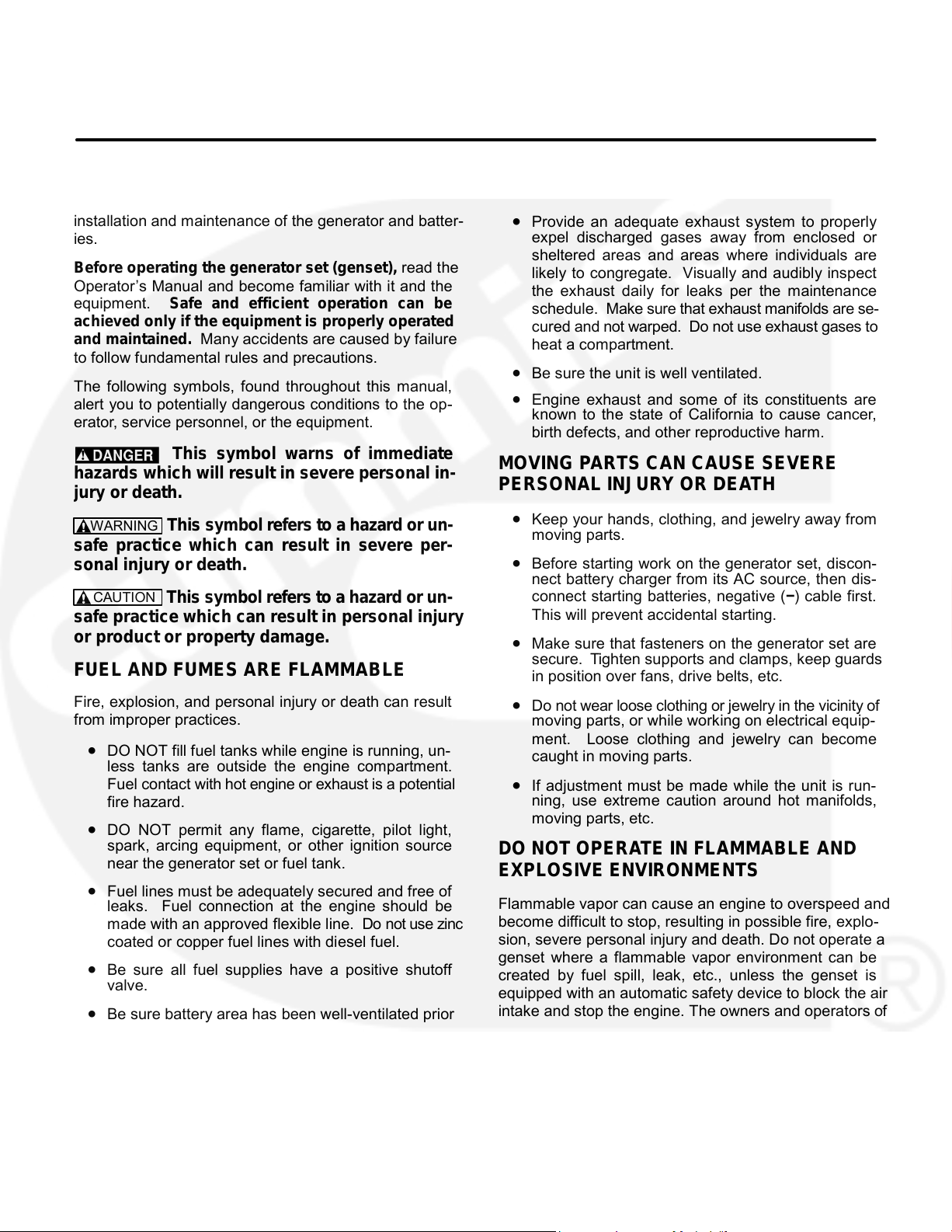
IMPORTANT SAFETY INSTRUCTIONS
EXHAUST GASES ARE DEADLY
SAVE THESE INSTRUCTIONS −
This manual contains
important instructions that should be followed during
• Provide an adequate exhaust system to properly
installation and maintenance of the generator and batter-
expel discharged gases away from enclosed or
ies.
sheltered areas and areas where individuals are
Before operating the generator set (genset), read the
likely to congregate. Visually and audibly inspect
Operator’s Manual and become familiar with it and the
the exhaust daily for leaks per the maintenance
equipment. Safe and efficient operation can be
schedule. Make sure that exhaust manifolds are se-
achieved only if the equipment is properly operated
cured and not warped. Do not use exhaust gases to
and maintained. Many accidents are caused by failure
heat a compartment.
to follow fundamental rules and precautions.
• Be sure the unit is well ventilated.
The following symbols, found throughout this manual,
Engine exhaust and some of its constituents are
alert you to potentially dangerous conditions to the op-
known to the state of California to cause cancer,
erator, service personnel, or the equipment.
birth defects, and other reproductive harm.
This symbol warns of immediate
MOVING PARTS CAN CAUSE SEVERE
hazards which will result in severe personal in-
PERSONAL INJURY OR DEATH
jury or death.
This symbol refers to a hazard or un-
moving parts.
safe practice which can result in severe per-
Before starting work on the generator set, discon-
sonal injury or death.
nect battery charger from its AC source, then dis-
connect starting batteries, negative (−) cable first.
This symbol refers to a hazard or un-
This will prevent accidental starting.
safe practice which can result in personal injury
or product or property damage.
secure. Tighten supports and clamps, keep guards
FUEL AND FUMES ARE FLAMMABLE
in position over fans, drive belts, etc.
Do not wear loose clothing or jewelry in the vicinity of
Fire, explosion, and personal injury or death can result
from improper practices.
moving parts, or while working on electrical equip-
ment. Loose clothing and jewelry can become
caught in moving parts.
less tanks are outside the engine compartment.
Fuel contact with hot engine or exhaust is a potential
ning, use extreme caution around hot manifolds,
fire hazard.
moving parts, etc.
spark, arcing equipment, or other ignition source
DO NOT OPERATE IN FLAMMABLE AND
near the generator set or fuel tank.
EXPLOSIVE ENVIRONMENT S
Flammable vapor can cause an engine to overspeed and
leaks. Fuel connection at the engine should be
become difficult to stop, resulting in possible fire, explo-
made with an approved flexible line. Do not use zinc
sion, severe personal injury and death. Do not operate a
coated or copper fuel lines with diesel fuel.
genset where a flammable vapor environment can be
created by fuel spill, leak, etc., unless the genset is
valve.
equipped with an automatic safety device to block the air
intake and stop the engine. The owners and operators of
to servicing near it. Lead-acid batteries emit a highly
the genset are solely responsible for operating the gen-
explosive hydrogen gas that can be ignited by arc-
set safely. Contact your authorized Cummins Power
ing, sparking, smoking, etc.
Generation distributor for more information.
LS-15M
iii
•
WARNING
CAUTION
• DO NOT fill fuel tanks while engine is running, un-
• DO NOT permit any flame, cigarette, pilot light,
• Fuel lines must be adequately secured and free of
• Keep your hands, clothing, and jewelry away from
•
• Make sure that fasteners on the generator set are
•
• If adjustment must be made while the unit is run-
• Be sure all fuel supplies have a positive shutoff
• Be sure battery area has been well-ventilated prior
Page 5
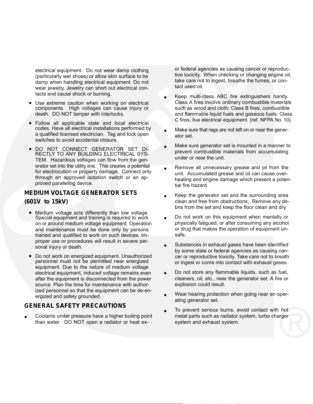
ELECTRICAL SHOCK CAN CAUSE
changer pressure cap while the engine is running.
To prevent severe scalding, let engine cool down
SEVERE PERSONAL INJURY OR DEATH
before removing coolant pressure cap. Turn cap
•
Remove electric power before removing protective
slowly, and do not open it fully until the pressure has
shields or touching electrical equipment. Use rub-
been relieved.
ber insulative mats placed on dry wood platforms
Used engine oils have been identified by some state
over floors that are metal or concrete when around
or federal agencies as causing cancer or reproduc-
electrical equipment. Do not wear damp clothing
tive toxicity. When checking or changing engine oil,
(particularly wet shoes) or allow skin surface to be
take care not to ingest, breathe the fumes, or con-
damp when handling electrical equipment. Do not
tact used oil.
wear jewelry. Jewelry can short out electrical con-
tacts and cause shock or burning.
Keep multi-class ABC fire extinguishers handy.
Class A fires involve ordinary combustible materials
components. High voltages can cause injury or
such as wood and cloth; Class B fires, combustible
death. DO NOT tamper with interlocks.
and flammable liquid fuels and gaseous fuels; Class
C fires, live electrical equipment. (ref. NFPA No. 10).
Follow all applicable state and local electrical
codes. Have all electrical installations performed by
•
Make sure that rags are not left on or near the gener-
a qualified licensed electrician. Tag and lock open
ator set.
switches to avoid accidental closure.
Make sure generator set is mounted in a manner to
DO NOT CONNECT GENERATOR SET DI-
prevent combustible materials from accumulating
RECTLY TO ANY BUILDING ELECTRICAL SYS-
under or near the unit.
TEM. Hazardous voltages can flow from the gen-
erator set into the utility line. This creates a potential
Remove all unnecessary grease and oil from the
for electrocution or property damage. Connect only
unit. Accumulated grease and oil can cause over-
through an approved isolation switch or an ap-
heating and engine damage which present a poten-
proved paralleling device.
tial fire hazard.
MEDIUM VOLTAGE GENERATOR SETS
Keep the generator set and the surrounding area
(601V to 15kV)
clean and free from obstructions. Remove any de-
bris from the set and keep the floor clean and dry.
Do not work on this equipment when mentally or
Special equipment and training is required to work
physically fatigued, or after consuming any alcohol
on or around medium voltage equipment. Operation
or drug that makes the operation of equipment un-
and maintenance must be done only by persons
safe.
trained and qualified to work on such devices. Im-
proper use or procedures will result in severe per-
Substances in exhaust gases have been identified
sonal injury or death.
by some state or federal agencies as causing can-
• Do not work on energized equipment. Unauthorized
cer or reproductive toxicity. Take care not to breath
personnel must not be permitted near energized
or ingest or come into contact with exhaust gases.
equipment. Due to the nature of medium voltage
Do not store any flammable liquids, such as fuel,
electrical equipment, induced voltage remains even
cleaners, oil, etc., near the generator set. A fire or
after the equipment is disconnected from the power
explosion could result.
source. Plan the time for maintenance with author-
ized personnel so that the equipment can be de-en-
Wear hearing protection when going near an oper-
ergized and safely grounded.
ating generator set.
GENERAL SAFETY PRECAUTIONS
To prevent serious burns, avoid contact with hot
Coolants under pressure have a higher boiling point
metal parts such as radiator system, turbo charger
than water. DO NOT open a radiator or heat ex-
system and exhaust system.
KEEP THIS MANUAL NEAR THE GENSET FOR EASY REFERENCE
iv
• Use extreme caution when working on electrical
•
•
•
•
• Medium voltage acts differently than low voltage.
•
•
•
•
•
•
•
•
•
Page 6
1. Introduction
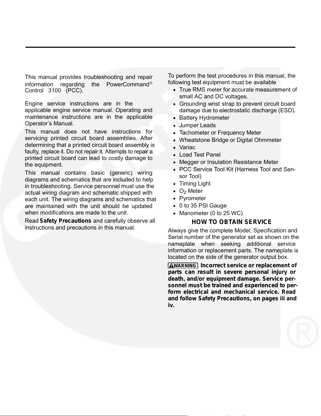
ABOUT THIS MANUAL
TEST EQUIPMENT
To perform the test procedures in this manual, the
This manual provides troubleshooting and repair
following test equipment must be available
information regarding the PowerCommand
Control 3100 (PCC).
True RMS meter for accurate measurement of
small AC and DC voltages.
Engine service instructions are in the
Grounding wrist strap to prevent circuit board
applicable engine service manual. Operating and
damage due to electrostatic discharge (ESD).
maintenance instructions are in the applicable
Battery Hydrometer
Operator’s Manual.
Jumper Leads
This manual does not have instructions for
Tachometer or Frequency Meter
servicing printed circuit board assemblies. After
Wheatstone Bridge or Digital Ohmmeter
determining that a printed circuit board assembly is
Variac
faulty, replace it. Do not repair it. Attempts to repair a
Load Test Panel
printed circuit board can lead to costly damage to
Megger or Insulation Resistance Meter
the equipment.
PCC Service Tool Kit (Harness Tool and Sen-
This manual contains basic (generic) wiring
sor Tool)
diagrams and schematics that are included to help
Timing Light
in troubleshooting. Service personnel must use the
O2 Meter
actual wiring diagram and schematic shipped with
Pyrometer
each unit. The wiring diagrams and schematics that
are maintained with the unit should be updated
0 to 35 PSI Gauge
when modifications are made to the unit.
Manometer (0 to 25 WC)
Read Safety Precautions and carefully observe all
HOW TO OBTAIN SERVICE
instructions and precautions in this manual.
Always give the complete Model, Specification and
Serial number of the generator set as shown on the
nameplate when seeking additional service
information or replacement parts. The nameplate is
located on the side of the generator output box.
WARNING Incorrect service or replacement of
parts can result in severe personal injury or
death, and/or equipment damage. Service per-
sonnel must be trained and experienced to per-
form electrical and mechanical service. Read
and follow Safety Precautions, on pages iii and
iv.
Copyright 2001 Cummins Power Generation. All rights reserved.
Cummins and PowerCommand are registered trademarks of Cummins Inc.
1-1
•
•
•
•
•
•
•
•
•
•
•
•
•
•
•
Page 7
SYSTEM OVERVIEW
more complete block diagram is provided in Section
3. A system schematic is provided in Section 8.
The PCC is a microprocessor-based control for
The PCC monitors frequency from both the mag-
Cummins generator sets. It provides fuel control
netic pick-up (MPU) and the main stator inputs. The
and engine speed governing, main alternator volt-
control sends a low power pulse-width modulated
age output regulation, and complete generator set
(PWM) signal to the fuel control actuator.
control and monitoring.
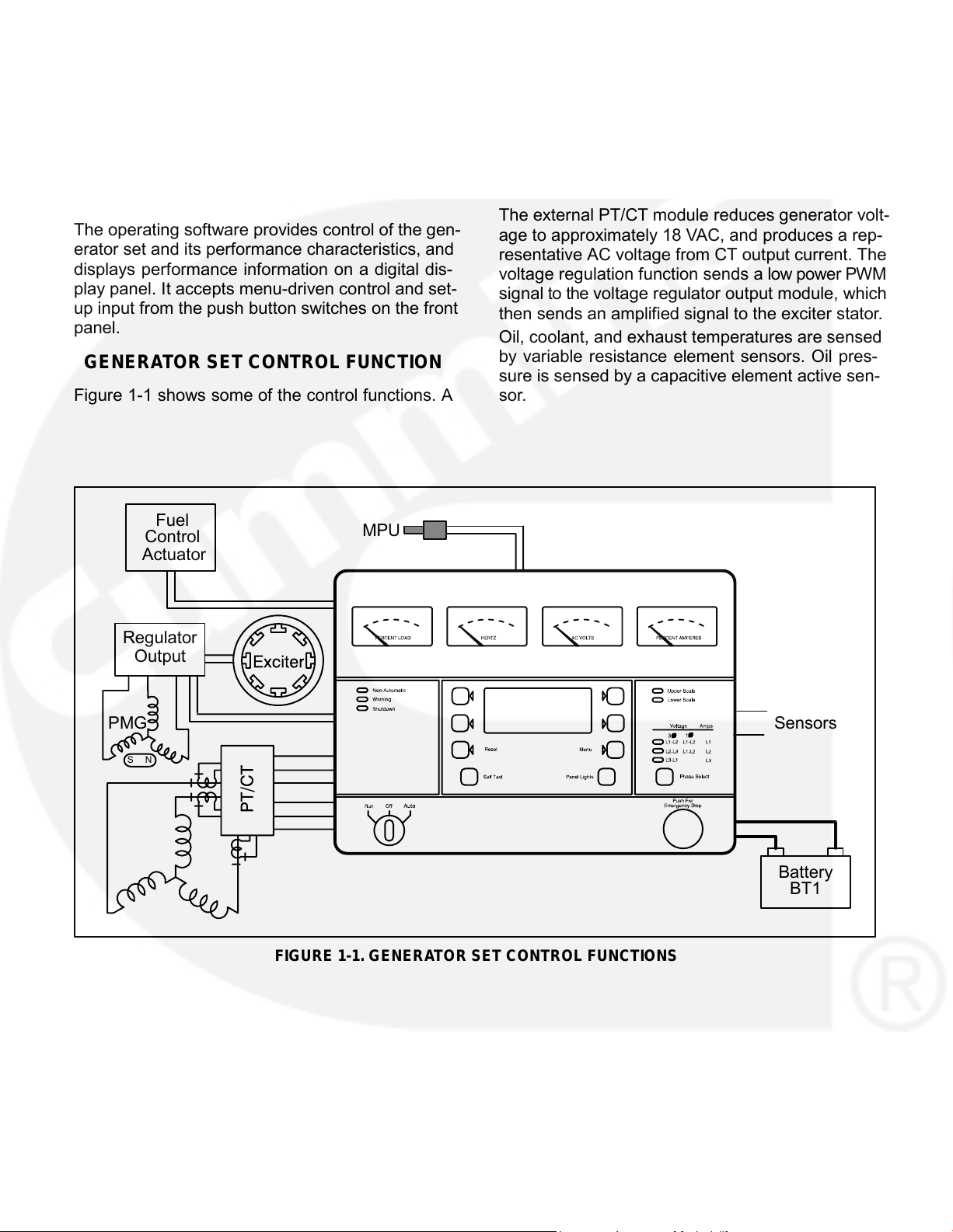
The external PT/CT module reduces generator volt-
The operating software provides control of the gen-
age to approximately 18 VAC, and produces a rep-
erator set and its performance characteristics, and
resentative AC voltage from CT output current. The
displays performance information on a digital dis-
voltage regulation function sends a low power PWM
play panel. It accepts menu-driven control and set-
signal to the voltage regulator output module, which
up input from the push button switches on the front
then sends an amplified signal to the exciter stator.
panel.
Oil, coolant, and exhaust temperatures are sensed
by variable resistance element sensors. Oil pres-
GENERATOR SET CONTROL FUNCTION
sure is sensed by a capacitive element active sen-
sor.
Figure 1-1 shows some of the control functions. A
Fuel
MPU
Control
Actuator
Regulator
Output
PMG
Sensors
S N
Battery
BT1
FIGURE 1-1. GENERATOR SET CONTROL FUNCTIONS
1-2
Page 8
2. Control Operation
GENERAL
PCC POWER ON / STANDBY MODE
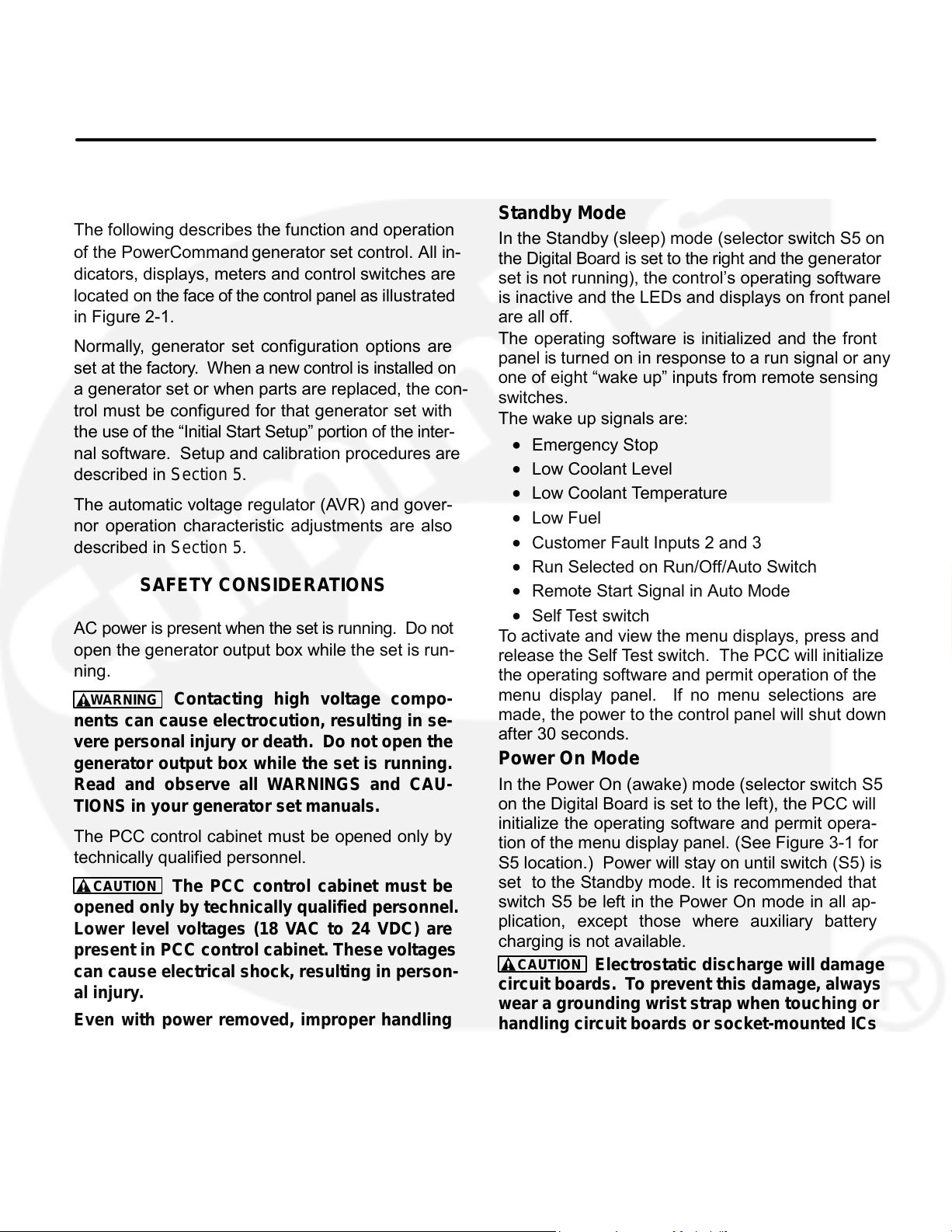
Standby Mode
The following describes the function and operation
In the Standby (sleep) mode (selector switch S5 on
of the PowerCommand generator set control. All in-
the Digital Board is set to the right and the generator
dicators, displays, meters and control switches are
set is not running), the control’s operating software
located on the face of the control panel as illustrated
is inactive and the LEDs and displays on front panel
in Figure 2-1.
are all off.
The operating software is initialized and the front
Normally, generator set configuration options are
panel is turned on in response to a run signal or any
set at the factory. When a new control is installed on
one of eight “wake up” inputs from remote sensing
a generator set or when parts are replaced, the con-
switches.
trol must be configured for that generator set with
The wake up signals are:
the use of the “Initial Start Setup” portion of the inter-
Emergency Stop
nal software. Setup and calibration procedures are
Low Coolant Level
described in Section 5.
Low Coolant Temperature
The automatic voltage regulator (AVR) and gover-
Low Fuel
nor operation characteristic adjustments are also
Customer Fault Inputs 2 and 3
described in Section 5.
Run Selected on Run/Off/Auto Switch
SAFETY CONSIDERATIONS
Remote Start Signal in Auto Mode
Self Test switch
AC power is present when the set is running. Do not
To activate and view the menu displays, press and
open the generator output box while the set is run-
release the Self Test switch. The PCC will initialize
ning.
the operating software and permit operation of the
menu display panel. If no menu selections are
WARNING
Contacting high voltage compo-
made, the power to the control panel will shut down
nents can cause electrocution, resulting in se-
after 30 seconds.
vere personal injury or death. Do not open the
Power On Mode
generator output box while the set is running.
In the Power On (awake) mode (selector switch S5
Read and observe all WARNINGS and CAU-
on the Digital Board is set to the left), the PCC will
TIONS in your generator set manuals.
initialize the operating software and permit opera-
The PCC control cabinet must be opened only by
tion of the menu display panel. (See Figure 3-1 for
technically qualified personnel.
S5 location.) Power will stay on until switch (S5) is
set to the Standby mode. It is recommended that
The PCC control cabinet must be
switch S5 be left in the Power On mode in all ap-
opened only by technically qualified personnel.
plication, except those where auxiliary battery
Lower level voltages (18 VAC to 24 VDC) are
charging is not available.
present in PCC control cabinet. These voltages
CAUTION
Electrostatic discharge will damage
can cause electrical shock, resulting in person-
circuit boards. To prevent this damage, always
al injury.
wear a grounding wrist strap when touching or
Even with power removed, improper handling
handling circuit boards or socket-mounted ICs
of components can cause electrostatic dis-
and when disconnecting or connecting harness
charge and damage to circuit components.
connectors.
2-1
CAUTION
•
•
•
•
•
•
•
•
Page 9
KILOWATT METER
FREQUENCY
AC
AC AMMETER
(PERCENT LOAD)
METER
VOLTMETER
(PERCENT AMPS)
(DUAL SCALE)
MENU
UPPER AND
ALPHANUMERIC
ACTIVE SWITCH
SELECTION
LOWER SCALE
DISPLAY
INDICATOR
SWITCH
INDICATOR
(1 of 6)
(1 of 4)
RUN/OFF/AUTO
SELF TEST
RESET
MENU
PANEL LAMP
EMERGENCY
SWITCH
SWITCH
SWITCH SWITCH
SWITCH
STOP PUSH
BUTTON
(Turn CW to reset)
NON-AUTOMATIC
PHASE SELECTOR
WARNING
SWITCH AND
SHUTDOWN
INDICATORS
STATUS INDICATORS
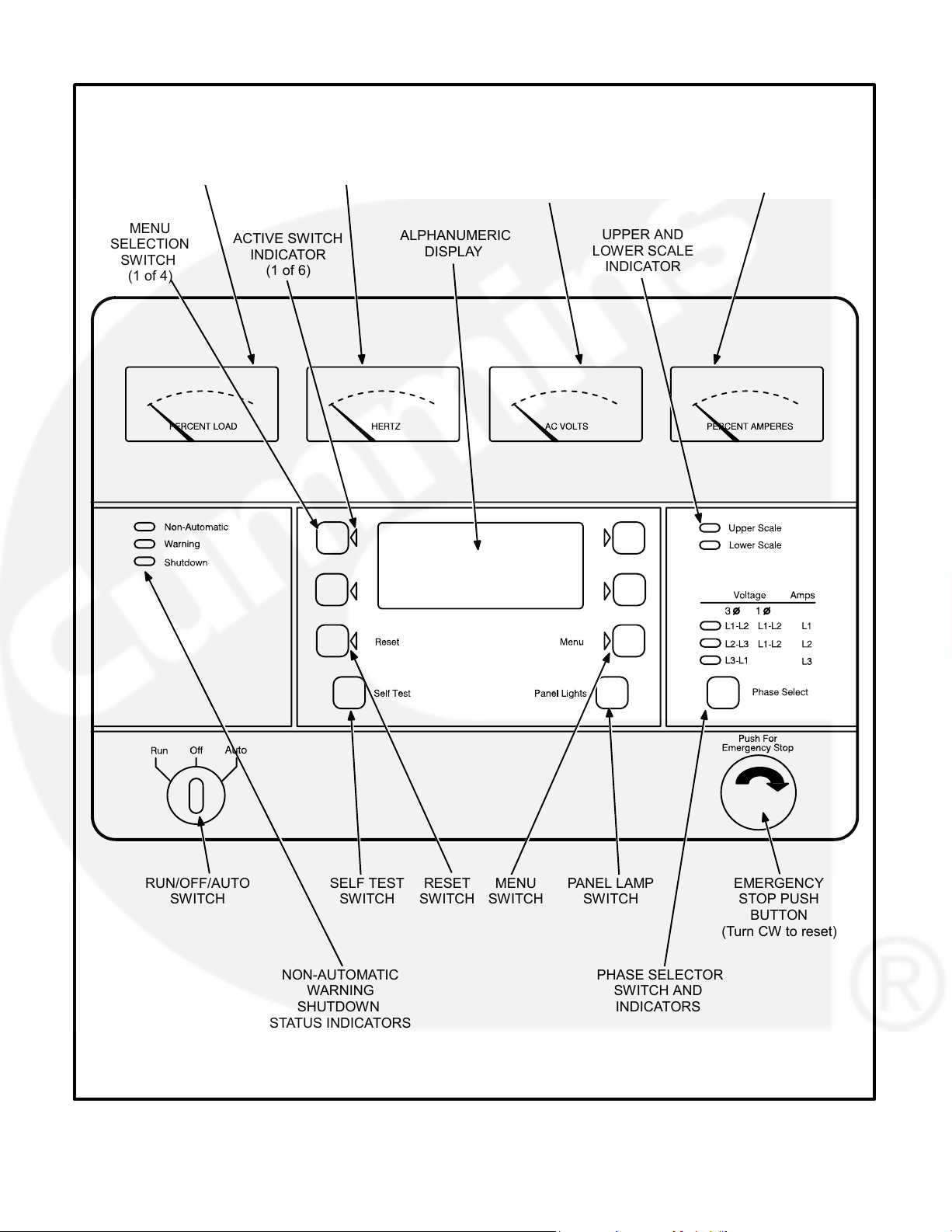
FIGURE 2-1. FRONT PANEL
2-2
Page 10
FRONT PANEL
operation of the menu display panel. If no menu
selections are made, a software timer will shut
Figure 2-1 shows the features of the front panel.
down the power after 30 seconds.
Panel Lights Switch: Press this switch to turn con-
AC Voltmeter: Dual scale instrument indicates AC
trol panel illumination on and off. The illumination
voltage. Measurement scale in use is shown on
will shut off after about eight minutes.
scale indicator lamp.
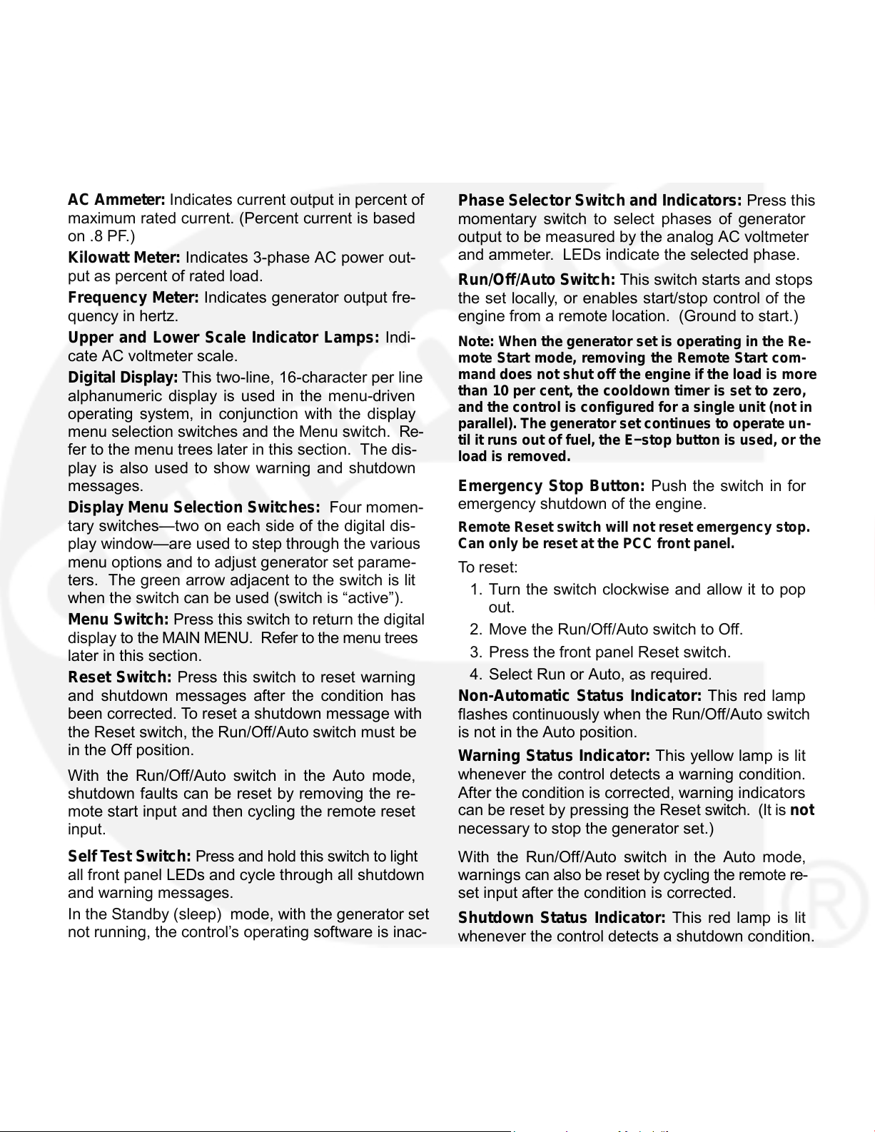
AC Ammeter: Indicates current output in percent of
Phase Selector Switch and Indicators: Press this
maximum rated current. (Percent current is based
momentary switch to select phases of generator
on .8 PF.)
output to be measured by the analog AC voltmeter
and ammeter. LEDs indicate the selected phase.
Kilowatt Meter: Indicates 3-phase AC power out-
put as percent of rated load.
Run/Off/Auto Switch: This switch starts and stops
Frequency Meter: Indicates generator output fre-
the set locally, or enables start/stop control of the
quency in hertz.
engine from a remote location. (Ground to start.)
Upper and Lower Scale Indicator Lamps: Indi-
Note: When the generator set is operating in the Re-
cate AC voltmeter scale.
mote Start mode, removing the Remote Start com-
mand does not shut off the engine if the load is more
Digital Display: This two-line, 16-character per line
than 10 per cent, the cooldown timer is set to zero,
alphanumeric display is used in the menu-driven
and the control is configured for a si n g le unit (not in
operating system, in conjunction with the display
parallel). The generator set continues to operate un-
menu selection switches and the Menu switch. Re-
til it runs out of fuel, the E−stop button is used, or the
fer to the menu trees later in this section. The dis-
load is removed.
play is also used to show warning and shutdown
Emergency Stop Button: Push the switch in for
messages.
emergency shutdown of the engine.
Display Menu Selection Switches: Four momen-
tary switches—two on each side of the digital dis-
Remote Reset switch will not reset emergency stop.
play window—are used to step through the various
Can only be reset at the PCC front panel.
menu options and to adjust generator set parame-
To reset:
ters. The green arrow adjacent to the switch is lit
1. Turn the switch clockwise and allow it to pop
when the switch can be used (switch is “active”).
out.
Menu Switch: Press this switch to return the digital
2. Move the Run/Off/Auto switch to Off.
display to the MAIN MENU. Refer to the menu trees
3. Press the front panel Reset switch.
later in this section.
4. Select Run or Auto, as required.
Reset Switch: Press this switch to reset warning
Non-Automatic Status Indicator: This red lamp
and shutdown messages after the condition has
been corrected. To reset a shutdown message with
flashes continuously when the Run/Off/Auto switch
the Reset switch, the Run/Off/Auto switch must be
is not in the Auto position.
in the Off position.
Warning Status Indicator: This yellow lamp is lit
whenever the control detects a warning condition.
With the Run/Off/Auto switch in the Auto mode,
After the condition is corrected, warning indicators
shutdown faults can be reset by removing the re-
can be reset by pressing the Reset switch. (It is not
mote start input and then cycling the remote reset
necessary to stop the generator set.)
input.
Self Test Switch: Press and hold this switch to light
With the Run/Off/Auto switch in the Auto mode,
all front panel LEDs and cycle through all shutdown
warnings can also be reset by cycling the remote re-
and warning messages.
set input after the condition is corrected.
In the Standby (sleep) mode, with the generator set
Shutdown Status Indicator: This red lamp is lit
not running, the control’s operating software is inac-
whenever the control detects a shutdown condition.
tive and the LEDs and displays on front panel are all
After the condition is corrected, shutdown indica-
off.
tors can be reset by turning the Run/Off/Auto switch
To activate and view the menu displays without
to the Off position, and pressing the Reset switch.
starting the generator set, press and hold the Self
In Auto mode, shutdowns can be reset by removing
Test switch until the front panel LEDs light. The
the remote start input and then cycling the remote
PCC will initialize the operating software and permit
reset input.
2-3
Page 11
Emergency
Stop shutdown status (Code 102 ) ca n be
reset only at the PCC front panel.
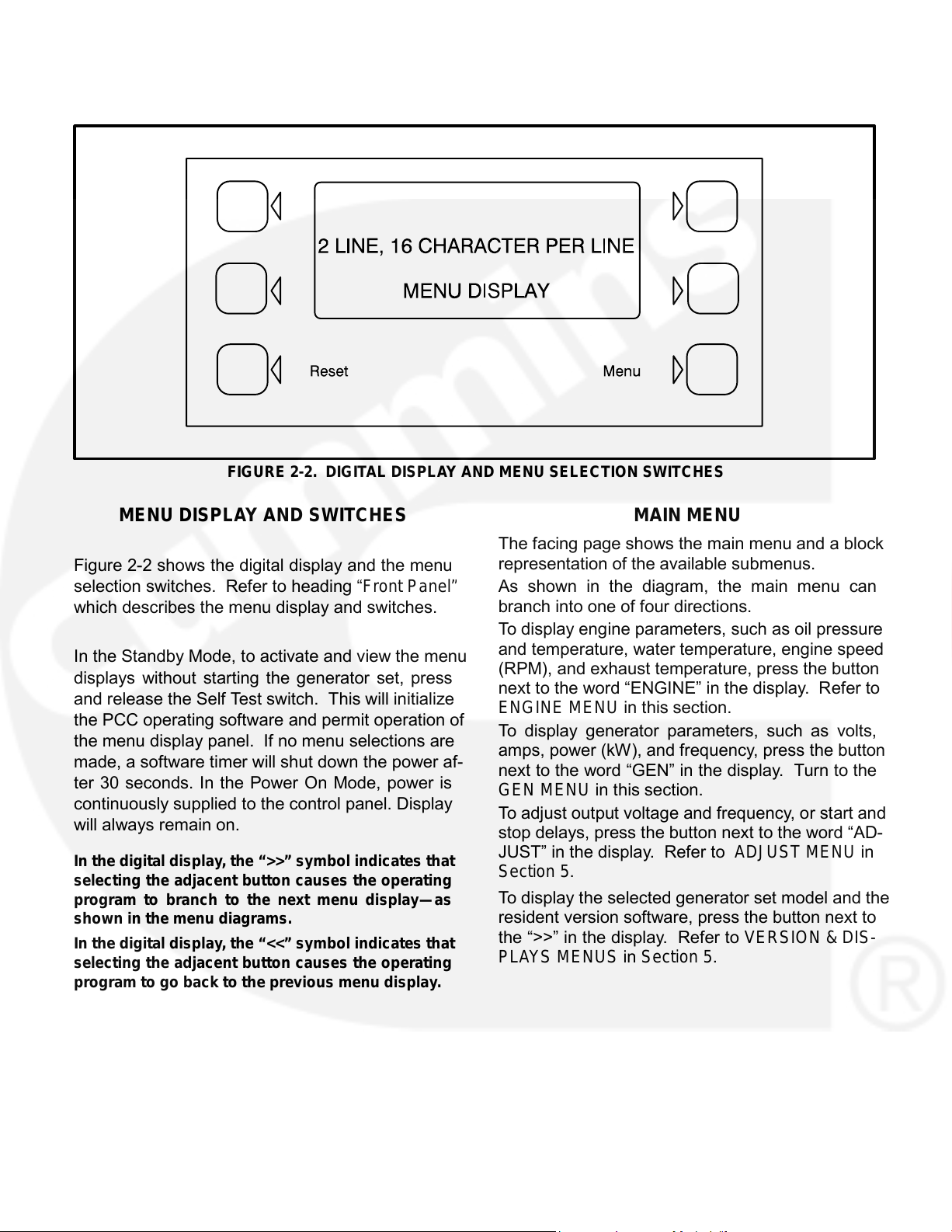
FIGURE 2-2. DIGITAL DISPLAY AND MENU SELECTION SWITCHES
MENU DISPLAY AND SWITCHES
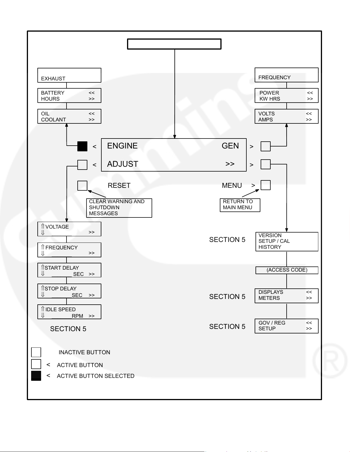
MAIN MENU
The facing page shows the main menu and a block
representation of the available submenus.
Figure 2-2 shows the digital display and the menu
selection switches. Refer to heading “Front Panel”
As shown in the diagram, the main menu can
branch into one of four directions.
which describes the menu display and switches.
To display engine parameters, such as oil pressure
and temperature, water temperature, engine speed
In the Standby Mode, to activate and view the menu
(RPM), and exhaust temperature, press the button
displays without starting the generator set, press
next to the word “ENGINE” in the display. Refer to
and release the Self Test switch. This will initialize
ENGINE MENU in this section.
the PCC operating software and permit operation of
To display generator parameters, such as volts,
the menu display panel. If no menu selections are
amps, power (kW), and frequency, press the button
made, a software timer will shut down the power af-
next to the word “GEN” in the display. Turn to the
ter 30 seconds. In the Power On Mode, power is
GEN MENU in this section.
continuously supplied to the control panel. Display
To adjust output voltage and frequency, or start and
will always remain on.
stop delays, press the button next to the word “AD-
JUST” in the display. Refer to ADJUST MENU in
In the digital display, the “>>” symbol indicates that
Section 5.
selecting the adjacent button causes the operating
To display the selected generator set model and the
program to branch to the next menu display—as
resident version software, press the button next to
shown in the menu diagrams.
the “>>” in the display. Refer to VERSIO N & DIS-
In the digital display, the “<<” symbol indicates that
PLAYS MENUS in Section 5.
selecting the adjacent button causes the operating
program to go back to the previous menu display.
2-4
Page 12
MAIN MENU
PAGES 2-6 & 2-7
PAGES 2-8 & 2-9
%GOV / REG
<<
RPM
<<
FREQUENCY
EXHAUST
BATTERY
<<
POWER
<<
HOURS
>>
KW HRS
>>
OIL
<<
VOLTS
<<
COOLANT
>>
AMPS
>>
ENGINE
GEN
< >
ADJUST
>>
< >
RESET MENU
>
CLEAR WARNING AND
RETURN TO
SHUTDOWN
MAIN MENU
MESSAGES
⇑ VOLTAGE
>>
_______
VERSION
SECTION 5
SETUP / CAL
FREQUENCY
HISTORY
>>
_______
(ACCESS CODE)
_______ SEC >>
STOP DELAY
DISPLAYS
<<
SECTION 5
METERS
>>
_______RPM >>
GOV / REG
<<
SECTION 5
SECTION 5
SETUP
>>
INACTIVE BUTTON
<
< ACTIVE BUTTON SELECTED
2-5
⇓
⇑
⇓
⇑ START DELAY
⇓
⇑
⇓ _______SEC >>
⇑ IDLE SPEED
⇓
ACTIVE BUTTON
Page 13
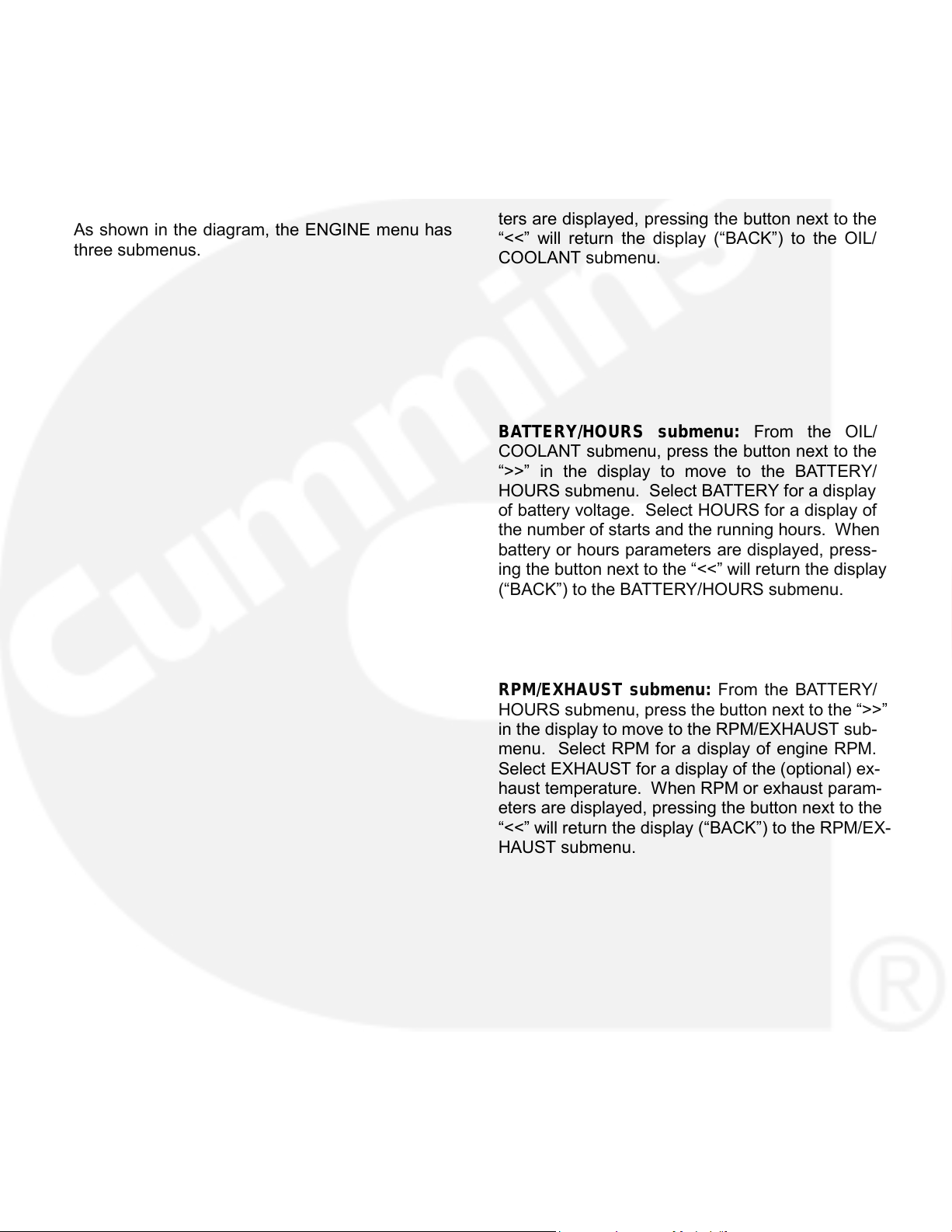
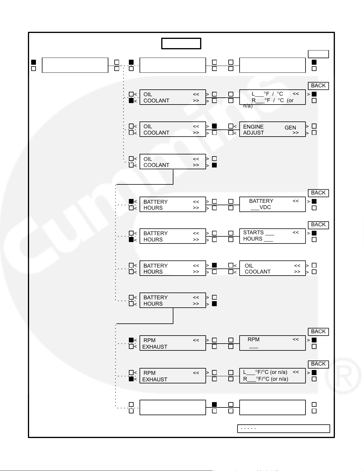
ENGINE MENU
OIL/COOLANT submenu: This is the first subme-
The facing page shows a block representation of
the ENGINE menu. If you press the button next to
nu. Select OIL for a display of oil pressure and oil
the word “ENGINE” in the display, the first ENGINE
temperature. Select COOLANT for a display of
submenu will appear.
coolant temperature. When oil or coolant parame-
ters are displayed, pressing the button next to the
As shown in the diagram, the ENGINE menu has
“<<” will return the display (“BACK”) to the OIL/
three submenus.
COOLANT submenu.
BATTERY/HOURS submenu: From the OIL/
COOLANT submenu, press the button next to the
“>>” in the display to move to the BATTERY/
HOURS submenu. Select BATTERY for a display
of battery voltage. Select HOURS for a display of
the number of starts and the running hours. When
battery or hours parameters are displayed, press-
ing the button next to the “<<” will return the display
(“BACK”) to the BATTERY/HOURS submenu.
RPM/EXHAUST submenu: From the BATTERY/
HOURS submenu, press the button next to the “>>”
in the display to move to the RPM/EXHAUST sub-
menu. Select RPM for a display of engine RPM.
Select EXHAUST for a display of the (optional) ex-
haust temperature. When RPM or exhaust param-
eters are displayed, pressing the button next to the
“<<” will return the display (“BACK”) to the RPM/EX-
HAUST submenu.
2-6
Page 14
ENGINE
BACK
___PSI / KPA
<<
< >
>
OIL
<<
ENGINE
GEN
< >
___°F / °C
ADJUST
>>
COOLANT
>>
< >
< >
BACK
L___°F / °C <<
< >
>
OIL
<<
R___°F / °C (or
COOLANT
>>
< >
n/a)
<>
GEN
< >
OIL
<<
ENGINE
COOLANT
>>
ADJUST
>>
< >
< >
< >
OIL
<<
COOLANT
>>
< >
BACK
BATTERY
<<
< >
>
BATTERY
<<
___VDC
HOURS
>>
< >
BACK
STARTS ___
<<
< >
>
BATTERY
<<
HOURS ___
HOURS
>>
< >
< >
BATTERY
<<
OIL
<<
< >
HOURS
>>
COOLANT
>>
< >
< >
< >
BATTERY
<<
HOURS
>>
< >
BACK
RPM
<<
< >
>
RPM
<<
___
<
EXHAUST
BACK
L___°F/°C (or n/a) <<
>
< >
RPM
<<
<
EXHAUST
< >
< >
RPM
<<
BATTERY
<<
HOURS
>> < EXHAUST
< >
Indicates “OR” Condition
2-7
R___°F/°C (or n/a)
Page 15
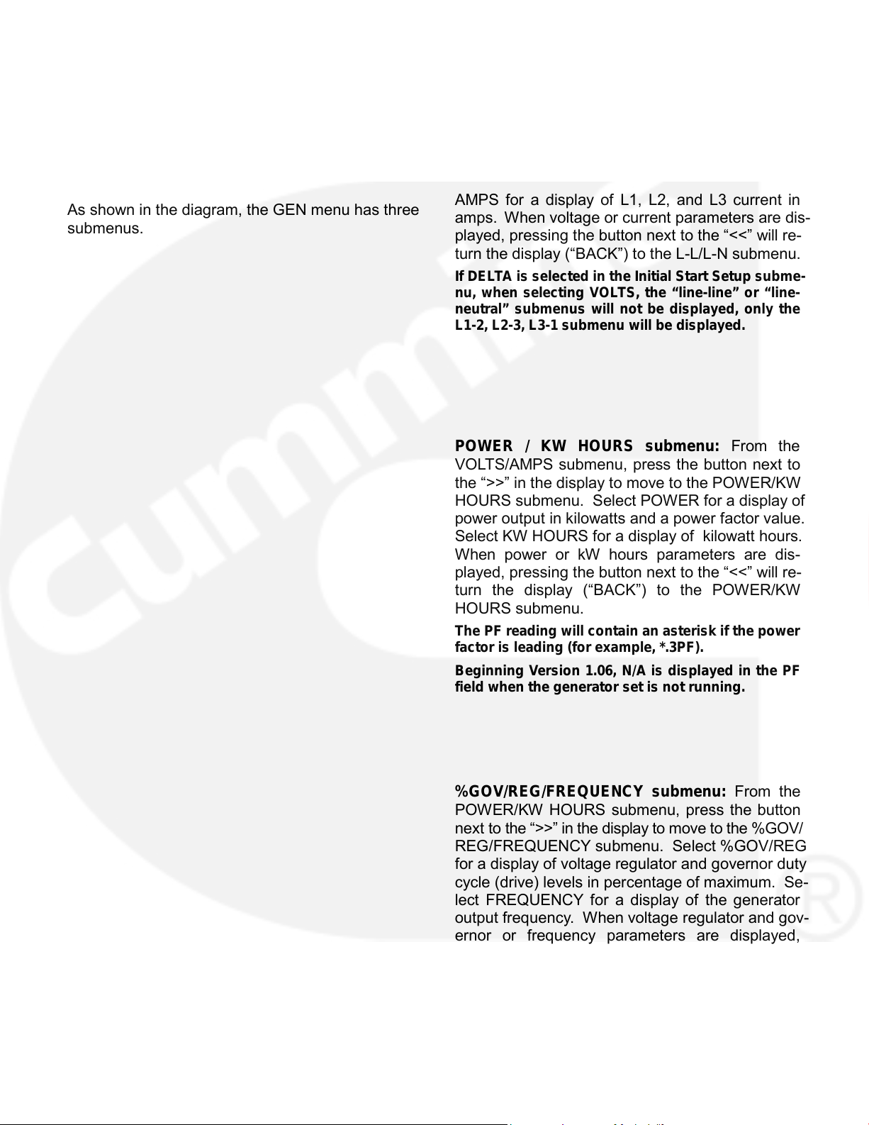
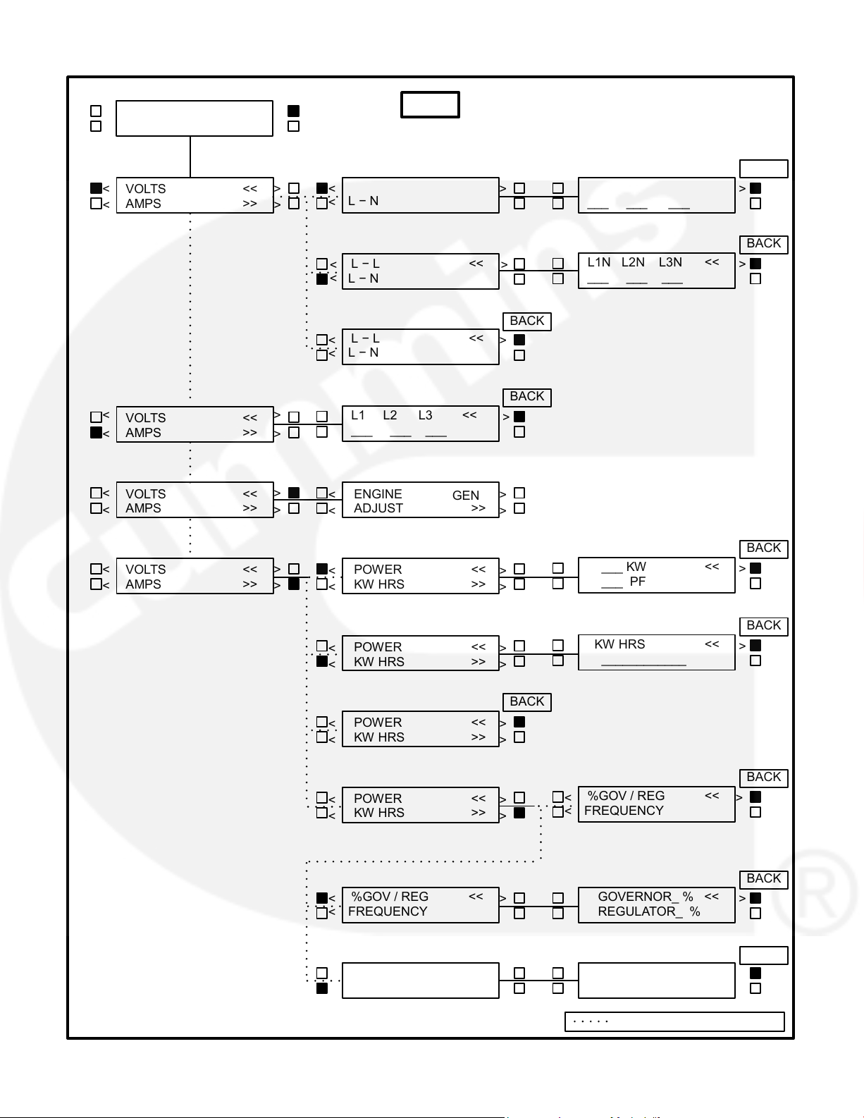
GEN MENU
VOLTS/AMPS submenu: This is the first subme-
The facing page shows a block representation of
the GEN menu. If you press the button next to the
nu. Select VOLTS for a display of a line-line or line-
word “GEN” in the display, the first GEN submenu
neutral selection. Select line-line (L-L) or line-neu-
will appear.
tral (L-N) for the desired voltage display. Select
AMPS for a display of L1, L2, and L3 current in
As shown in the diagram, the GEN menu has three
amps. When voltage or current parameters are dis-
submenus.
played, pressing the button next to the “<<” will re-
turn the display (“BACK”) to the L-L/L-N submenu.
If DELTA is selected in the Initial Start Setup subme-
nu, when selecting VOLTS, the “line-line” or “line-
neutral” submenus will not be displayed, only the
L1-2, L2-3, L3-1 submenu will be displayed.
POWER / KW HOURS submenu: From the
VOLTS/AMPS submenu, press the button next to
the “>>” in the display to move to the POWER/KW
HOURS submenu. Select POWER for a display of
power output in kilowatts and a power factor value.
Select KW HOURS for a display of kilowatt hours.
When power or kW hours parameters are dis-
played, pressing the button next to the “<<” will re-
turn the display (“BACK”) to the POWER/KW
HOURS submenu.
The PF reading will contain an asteri sk if the power
factor is leading (for example, *.3PF).
Beginning Version 1.06, N/A is displayed in the PF
field when the generator set is n o t running.
%GOV/REG/FREQUENCY submenu: From the
POW ER/KW HOURS submenu, press the button
next to the “>>” in the display to move to the %GOV/
REG/FREQUENCY submenu. Select %GOV/REG
for a display of voltage regulator and governor duty
cycle (drive) levels in percentage of maximum. Se-
lect FREQUENCY for a display of the generator
output frequency. When voltage regulator and gov-
ernor or frequency parameters are displayed,
pressing the button next to the “<<” will return the
display (“BACK”) to the %GOV/REG/FREQUENCY
submenu.
2-8
Page 16
GEN
ENGINE
GEN
< >
ADJUST
>>
< >
BACK
L − L <<
L1-2 L2-3 L3-1 <<
< >
VOLTS
<<
< >
>
___ ___ ___
AMPS
>>
< >
<
L − N
BACK
<<
L − L <<
L1N L2N L3N
>
< >
___ ___ ___
< L − N
BACK
L − L <<
< >
<
L − N
BACK
L1 L2 L3
>
<> <<
VOLTS
<<
___ ___ ___
AMPS
>>
< >
<>
GEN
VOLTS
<<
ENGINE
< >
AMPS
>>
ADJUST
>>
< >
< >
BACK
___ KW
<<
>
< >
VOLTS
<<
POWER
<<
< >
___ PF
AMPS
>>
KW HRS
>>
< >
< >
BACK
KW HRS
<< > POWER
<<
< >
____________
KW HRS
>>
< >
BACK
POWER
<<
< >
KW HRS
>>
< >
BACK
%GOV / REG
<<
< >
POWER
<<
< >
KW HRS
>>
<
FREQUENCY
< >
BACK
%GOV / REG
<<
GOVERNOR_ % <<
< >
>
REGULATOR_ %
<
FREQUENCY
BACK
%GOV / REG
<<
FREQUENCY
<<
< >
>
___ HZ
<
FREQUENCY
Indicates “OR” Condition
2-9
Page 17

THIS PAGE LEFT INTENTIONALLY BLANK
2-10
Page 18
3. Circuit Boards and Modules
GENERAL
The system schematics are provided in Sect ion 9 of
this manual.
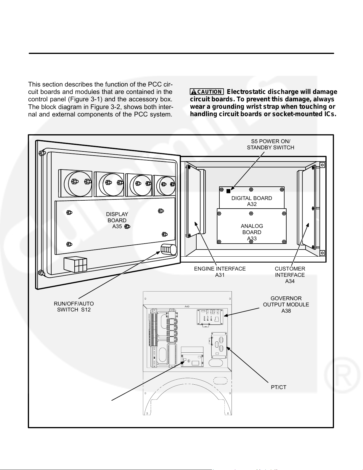
This section describes the function of the PCC cir-
cuit boards and modules that are contained in the
CAUTION
Electrostatic discharge will damage
circuit boards. To prevent this damage, always
control panel (Figure 3-1) and the accessory box.
wear a grounding wrist strap when touching or
The block diagram in Figure 3-2, shows both inter-
handling circuit boards or socket-mounted ICs.
nal and external components of the PCC system.
S5 POWER ON/
STANDBY SWITCH
DIGITAL BOARD
A32
DISPLAY
BOARD
ANALOG
A35
BOARD
A33
ENGINE INTERFACE
CUSTOMER
A31
INTERFACE
A34
GOVERNOR
RUN/OFF/AUTO
OUTPUT MODULE
SWITCH S12
A38
PT/CT
BOARD
A36
VOLTAGE REGULATOR
ACCESSORY
OUTPUT MODULE
BOX (HC 4/5)
A37
FIGURE 3-1. CIRCUIT BOARD LOCATIONS
3-1
Page 19
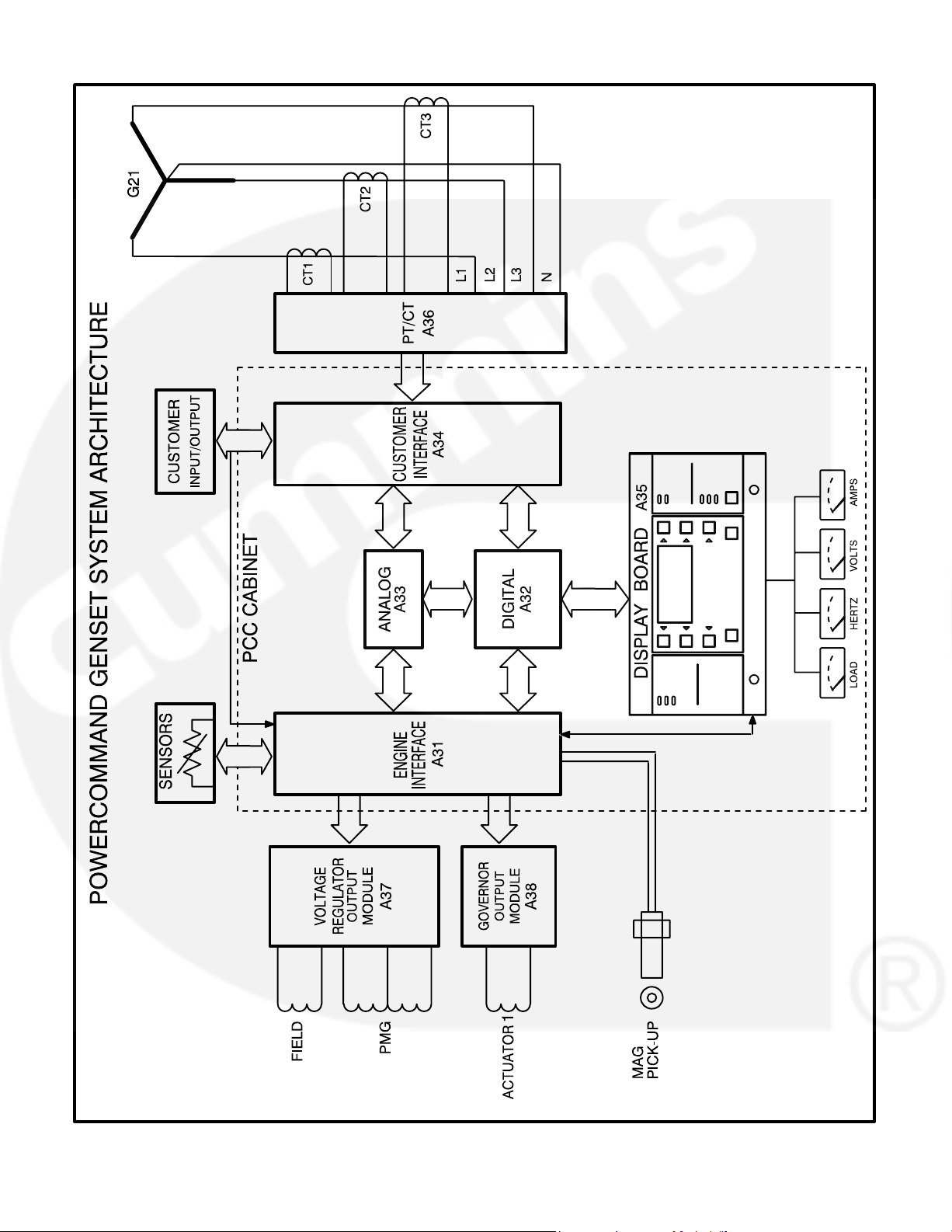
FIGURE 3-2. BLOCK DIAGRAM
3-2
Page 20
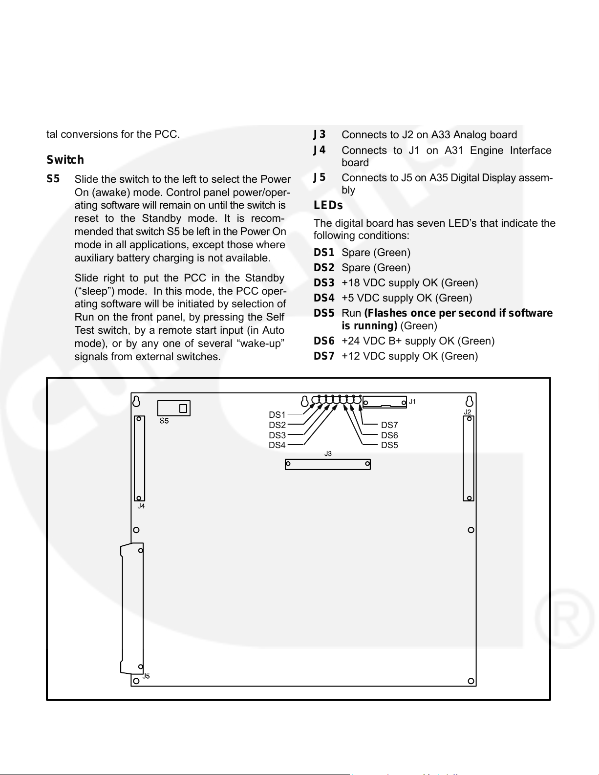
DIGITAL BOARD (A32)
Connectors
The digital board has five connectors. They are:
The digital circuit board (Figure 3-3) contains the
J1
Serial Interface RS232
microprocessor and the operational software for the
J2
Connects to J4 on A34 Customer Interface
control. It connects to all other boards inside the
board
control. This board also provides the analog-to-digi-
tal conversions for the PCC.
J3
Connects to J2 on A33 Analog board
J4
Connects to J1 on A31 Engine Interface
Switch
board
J5
Connects to J5 on A35 Digital Display assem-
S5
Slide the switch to the left to select the Power
bly
On (awake) mode. Control panel power/oper-
LEDs
ating software will remain on until the switch is
reset to the Standby mode. It is recom-
The digital board has seven LED’s that indicate the
mended that switch S5 be left in the Power On
following conditions:
mode in all applications, except those where
DS1 Spare (Green)
auxiliary battery charging is not available.
DS2 Spare (Green)
Slide right to put the PCC in the Standby
DS3 +18 VDC supply OK (Green)
(“sleep”) mode. In this mode, the PCC oper-
DS4 +5 VDC supply OK (Green)
ating software will be initiated by selection of
DS5 Run (Flashes once per second if software
Run on the front panel, by pressing the Self
is running) (Green)
Test switch, by a remote start input (in Auto
DS6 +24 VDC B+ supply OK (Green)
mode), or by any one of several “wake-up”
DS7 +12 VDC supply OK (Green)
signals from external switches.
DS1
DS2
DS7
DS3
DS6
DS4
DS5
FIGURE 3-3. DIGITAL BOARD
3-3
Page 21
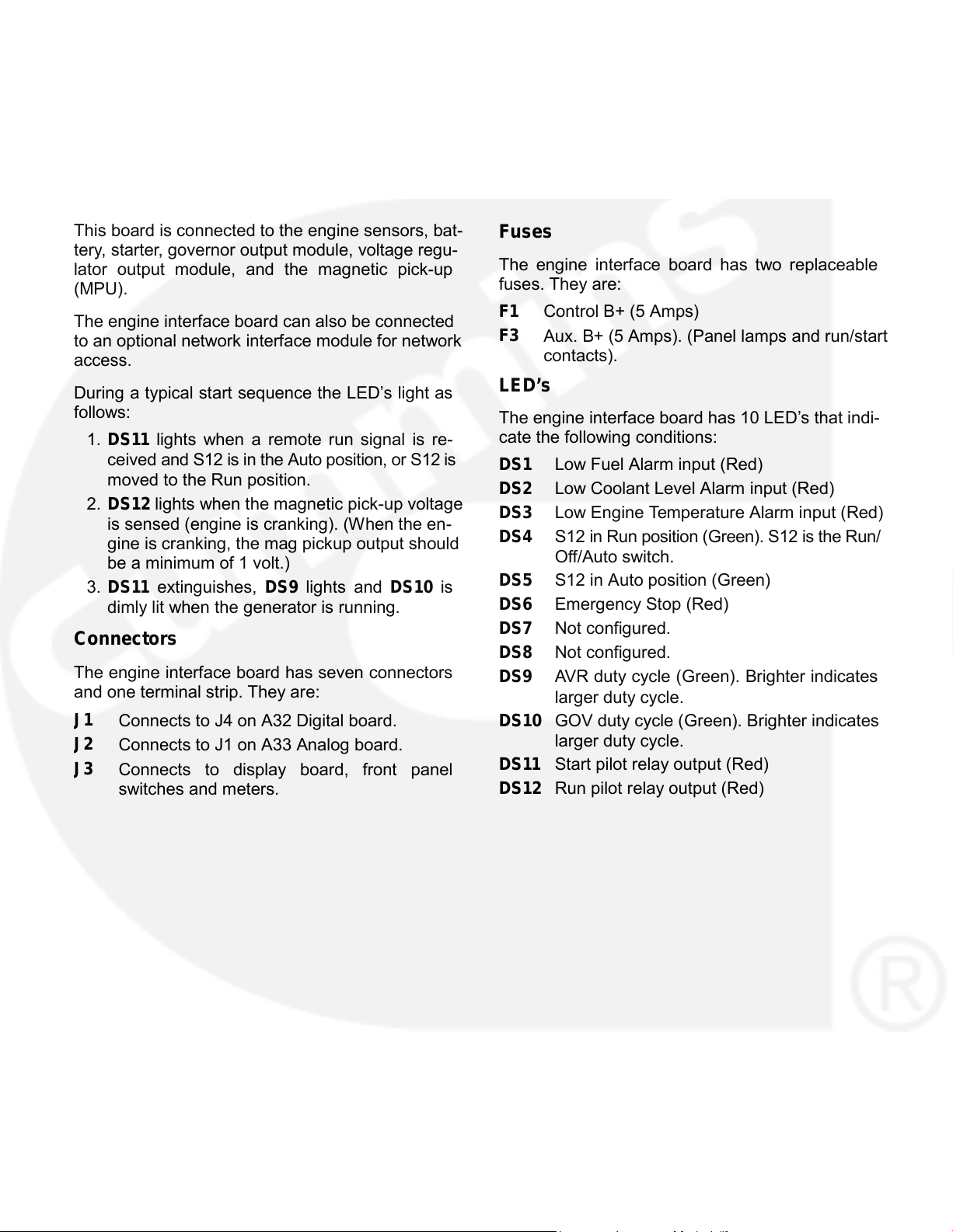
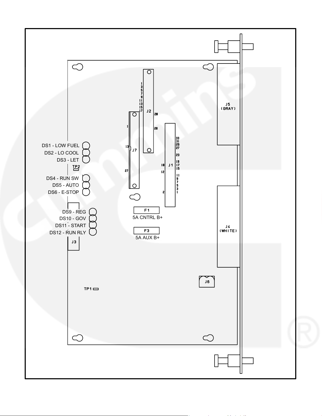
ENGINE INTERFACE BOARD (A31)
J4
Connects to customer connections and to en-
gine harness which includes magnetic pick-
The engine interface board (Figure 3-4) reads user
up.
control inputs, monitors engine, generator and sys-
J5
Connects to engine sensors.
tem status, and initiates the appropriate action for
J6
Connects to Genset Control module (GCM).
normal operating and fault conditions (warning or
shutdown).
J7
Connects to Genset Control module (GCM).
This board is connected to the engine sensors, bat-
Fuses
tery, starter, governor output module, voltage regu-
The engine interface board has two replaceable
lator output module, and the magnetic pick-up
fuses. They are:
(MPU).
F1
Control B+ (5 Amps)
The engine interface board can also be connected
F3
Aux. B+ (5 Amps). (Panel lamps and run/start
to an optional network interface module for network
contacts).
access.
LED’s
During a typical start sequence the LED’s light as
follows:
The engine interface board has 10 LED’s that indi-
cate the following conditions:
1. DS11 lights when a remote run signal is re-
ceived and S12 is in the Auto position, or S12 is
DS1 Low Fuel Alarm input (Red)
moved to the Run position.
DS2 Low Coolant Level Alarm input (Red)
2. DS12 lights when the magnetic pick-up voltage
DS3 Low Engine Temperature Alarm input (Red)
is sensed (engine is cranking). (When the en-
DS4 S12 in Run position (Green). S12 is the Run/
gine is cranking, the mag pickup output should
Off/Auto switch.
be a minimum of 1 volt.)
DS5 S12 in Auto position (Green)
3. DS11 extinguishes, DS9 lights and DS10 is
DS6 Emergency Stop (Red)
dimly lit when the generator is running.
DS7 Not configured.
Connectors
DS8 Not configured.
The engine interface board has seven connectors
DS9 AVR duty cycle (Green). Brighter indicates
and one terminal strip. They are:
larger duty cycle.
J1
Connects to J4 on A32 Digital board.
DS10 GOV duty cycle (Green). Brighter indicates
larger duty cycle.
J2
Connects to J1 on A33 Analog board.
DS11 Start pilot relay output (Red)
J3
Connects to display board, front panel
DS12 Run pilot relay output (Red)
switches and meters.
3-4
Page 22
DS1 - LOW FUEL
DS2 - LO COOL
DS3 - LET
DS4 - RUN SW
DS5 - AUTO
DS6 - E-STOP
DS9 - REG
5A CNTRL B+
DS10 - GOV
DS11 - START
DS12 - RUN RLY
5A AUX B+
FIGURE 3-4. ENGINE INTERFACE BOARD
3-5
Page 23
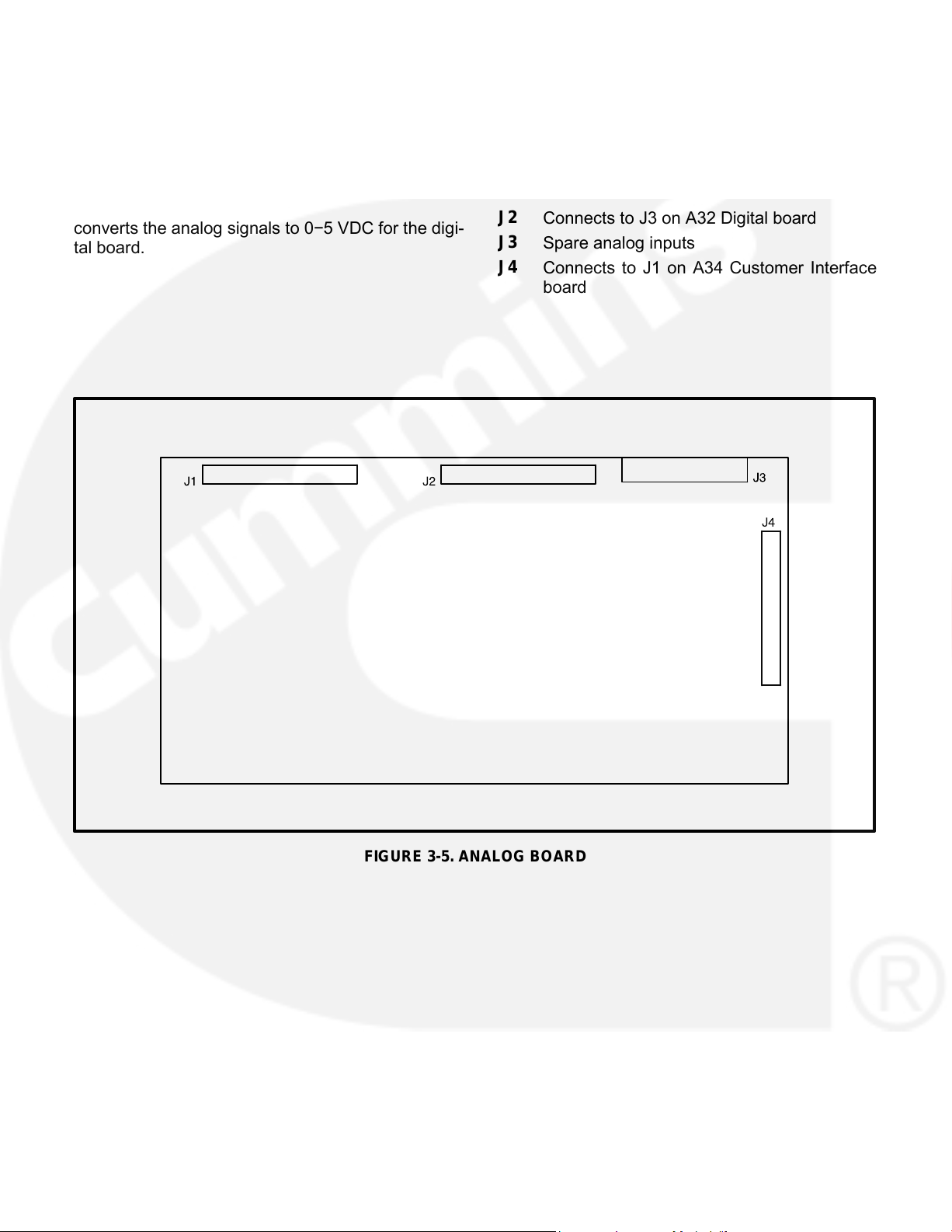
ANALOG BOARD (A33)
Connectors
The analog board (Figure 3-5) is the only circuit
The analog board has four connectors with ribbon
board inside the control that has no LED’s. There
cables permanently soldered to them. They are:
are two versions of the analog board that are used
J1
Connects to J2 on A31 Engine Interface
for paralleling and non-paralleling systems.
board
This board interprets all analog input signals and
J2
Connects to J3 on A32 Digital board
converts the analog signals to 0−5 VDC for the digi-
J3
Spare analog inputs
tal board.
J4
Connects to J1 on A34 Customer Interface
board
FIGURE 3-5. ANALOG BOARD
3-6
Page 24
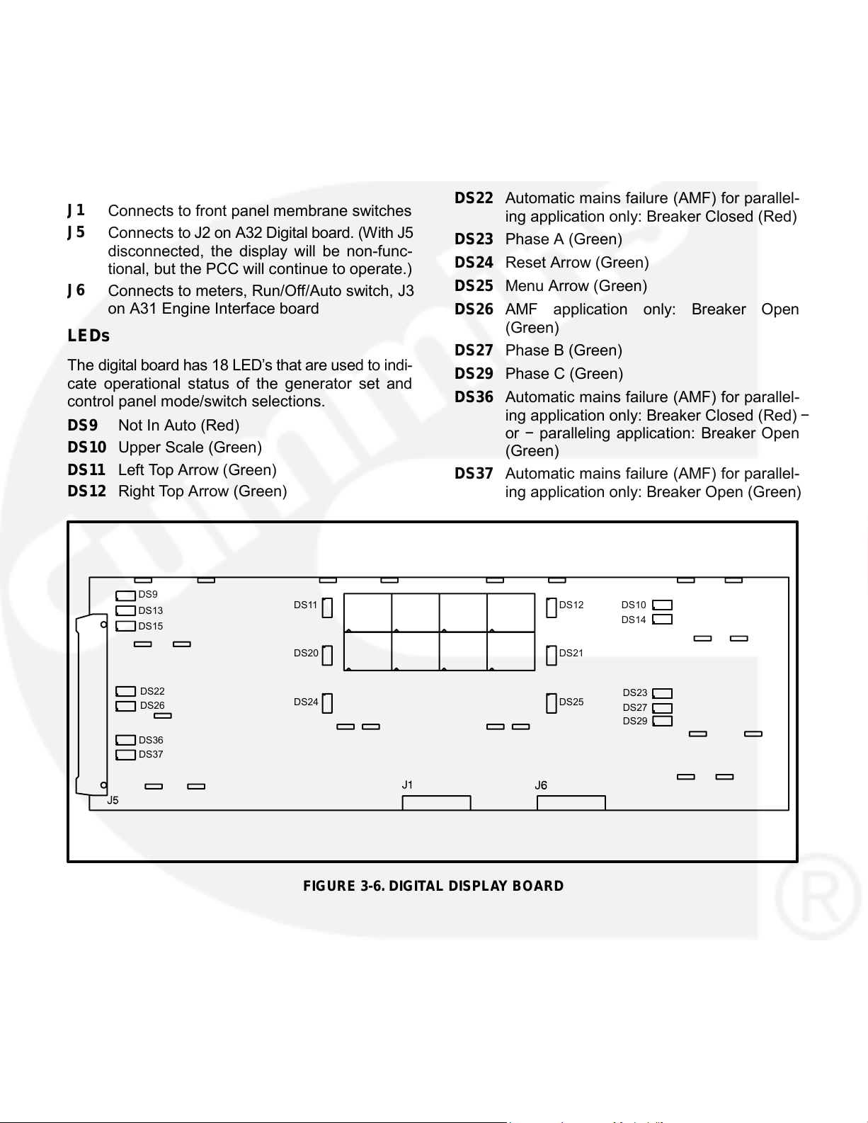
DIGITAL DISPLAY BOARD (A35)
DS13 Warning (Amber)
DS14 Lower Scale (Green)
The digital board (Figure 3-6) connects to all meters
and the LED display.
DS15 Shutdown (Red)
DS20 Left Bottom Arrow (Green)
Connectors
DS21 Right Bottom Arrow (Green)
The digital board has three connectors. They are:
DS22 Automatic mains failure (AMF) for parallel-
J1
Connects to front panel membrane switches
ing application only: Breaker Closed (Red)
J5
Connects to J2 on A32 Digital board. (With J5
DS23 Phase A (Green)
disconnected, the display will be non-func-
DS24 Reset Arrow (Green)
tional, but the PCC will continue to operate.)
DS25 Menu Arrow (Green)
J6
Connects to meters, Run/Off/Auto switch, J3
on A31 Engine Interface board
DS26 AMF application only: Breaker Open
(Green)
LEDs
DS27 Phase B (Green)
The digital board has 18 LED’s that are used to indi-
DS29 Phase C (Green)
cate operational status of the generator set and
DS36 Automatic mains failure (AMF) for parallel-
control panel mode/switch selections.
ing application only: Breaker Closed (Red) −
DS9 Not In Auto (Red)
or − paralleling application: Breaker Open
DS10 Upper Scale (Green)
(Green)
DS11 Left Top Arrow (Green)
DS37 Automatic mains failure (AMF) for parallel-
DS12 Right Top Arrow (Green)
ing application only: Breaker Open (Green)
DS9
DS11
DS12
DS10
DS13
DS14
DS15
DS20
DS21
DS22
DS23
DS24
DS25
DS26
DS27
DS29
DS36
DS37
FIGURE 3-6. DIGITAL DISPLAY BOARD
3-7
Page 25
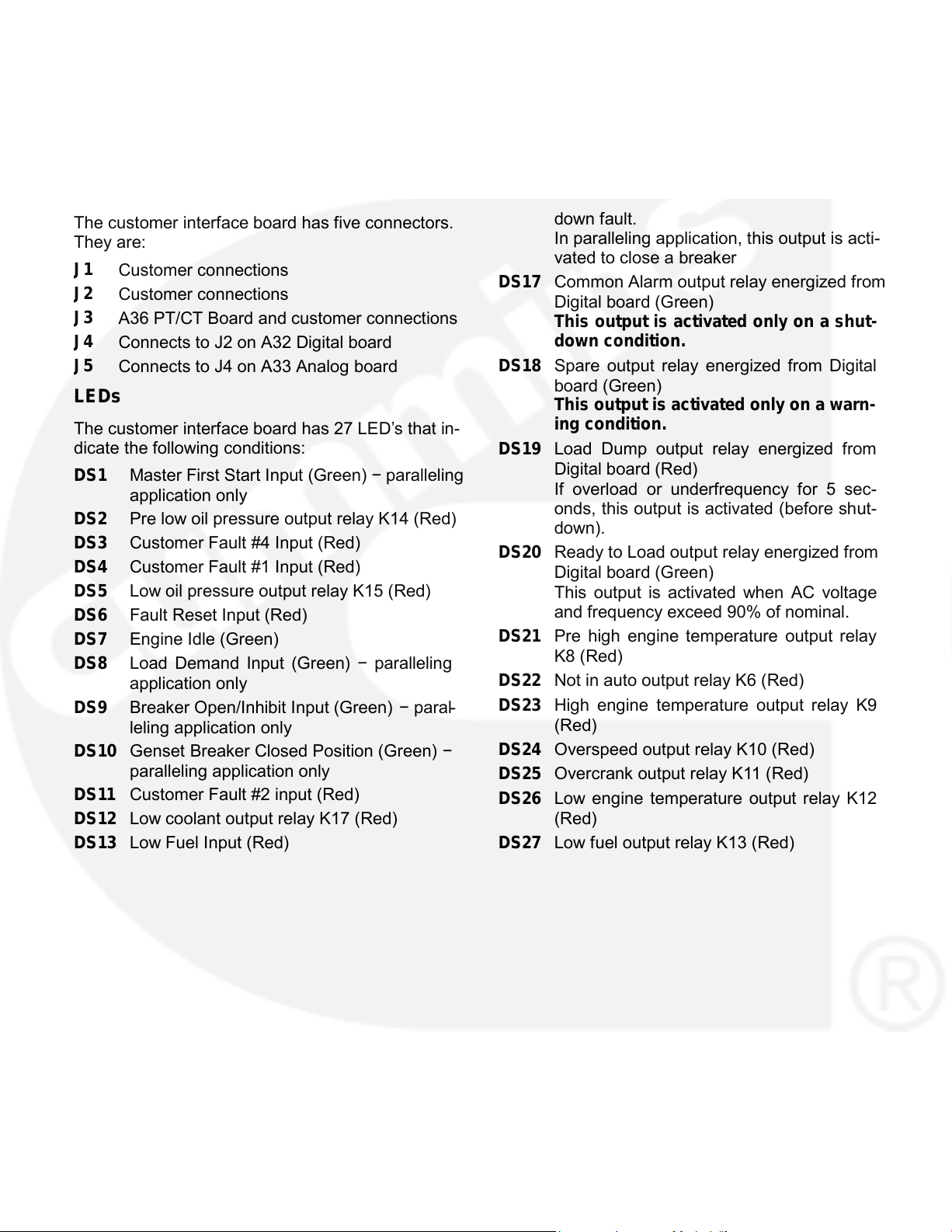
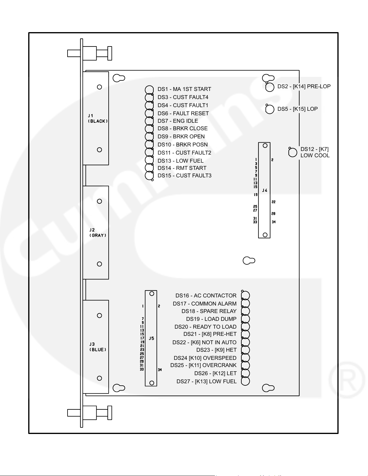
CUSTOMER INTERFACE BOAR D ( A34)
DS14 Remote Start input (Green)
DS15 Customer Fault #3 input (Red)
The customer interface board (Figure 3-7) connects
to the PT/CT board to bring in voltage and current. It
DS16 Breaker Control input relay energized from
also connects to customer inputs and outputs.
Digital board (Green).
In single set application, this output is acti-
Connectors
vated for a breaker trip when there is a shut-
down fault.
The customer interface board has five connectors.
In paralleling application, this output is acti-
They are:
vated to close a breaker
J1
Customer connections
DS17 Common Alarm output relay energized from
J2
Customer connections
Digital board (Green)
J3
A36 PT/CT Board and customer connections
This output is activated only on a shut-
down condition.
J4
Connects to J2 on A32 Digital board
DS18 Spare output relay energized from Digital
J5
Connects to J4 on A33 Analog board
board (Green)
LEDs
This output is activated only on a warn-
ing condition.
The customer interface board has 27 LED’s that in-
dicate the following conditions:
DS19 Load Dump output relay energized from
Digital board (Red)
DS1 Master First Start Input (Green) − paralleling
If overload or underfrequency for 5 sec-
application only
onds, this output is activated (before shut-
DS2 Pre low oil pressure output relay K14 (Red)
down).
DS3 Customer Fault #4 Input (Red)
DS20 Ready to Load output relay energized from
DS4 Customer Fault #1 Input (Red)
Digital board (Green)
DS5 Low oil pressure output relay K15 (Red)
This output is activated when AC voltage
and frequency exceed 90% of nominal.
DS6 Fault Reset Input (Red)
DS21 Pre high engine temperature output relay
DS7 Engine Idle (Green)
K8 (Red)
DS8 Load Demand Input (Green) − paralleling
DS22 Not in auto output relay K6 (Red)
application only
DS23 High engine temperature output relay K9
DS9 Breaker Open/Inhibit Input (Green) − paral-
(Red)
leling application only
DS24 Overspeed output relay K10 (Red)
DS10 Genset Breaker Closed Position (Green) −
paralleling application only
DS25 Overcrank output relay K11 (Red)
DS11 Customer Fault #2 input (Red)
DS26 Low engine temperature output relay K12
(Red)
DS12 Low coolant output relay K17 (Red)
DS27 Low fuel output relay K13 (Red)
DS13 Low Fuel Input (Red)
3-8
Page 26
DS2 - [K14] PRE-LOP
DS1 - MA 1ST START
DS3 - CUST FAULT4
DS4 - CUST FAULT1
DS5 - [K15] LOP
DS6 - FAULT RESET
DS7 - ENG IDLE
DS8 - BRKR CLOSE
DS9 - BRKR OPEN
DS10 - BRKR POSN
DS12 - [K7]
DS11 - CUST FAULT2
LOW COOL
DS13 - LOW FUEL
DS14 - RMT START
DS15 - CUST FAULT3
DS16 - AC CONTACTOR
DS17 - COMMON ALARM
DS18 - SPARE RELAY
DS19 - LOAD DUMP
DS20 - READY TO LOAD
DS21 - [K8] PRE-HET
DS22 - [K6] NOT IN AUTO
DS23 - [K9] HET
DS24 [K10] OVERSPEED
DS25 - [K11] OVERCRANK
DS26 - [K12] LET
DS27 - [K13] LOW FUEL
FIGURE 3-7. CUSTOMER INTERFACE BOARD
3-9
Page 27
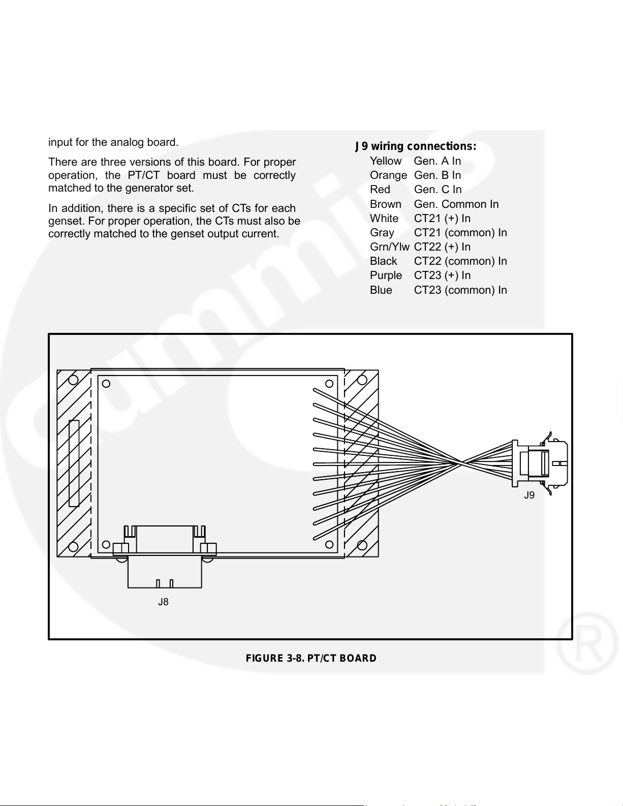
PT/CT BOARD (A36)
Connectors
The PT/CT board has two connectors. They are:
The PT/CT board (Figure 3-8) is mounted inside the
accessory box. This board converts generator out-
J8
Connects to J3 on A34 Customer Interface
put voltage to approximately 18 VAC levels for the
board
analog board. It also converts CT .55 amp (at full
J9
Connects to AC harness (generator output
load) output to approximately 1.65 VAC (at full load)
voltage and CTs)
input for the analog board.
J9 wiring connections:
Yellow Gen. A In
There are three versions of this board. For proper
operation, the PT/CT board must be correctly
Orange Gen. B In
matched to the generator set.
Red
Gen. C In
Brown Gen. Common In
In addition, there is a specific set of CTs for each
White CT21 (+) In
genset. For proper operation, the CTs must also be
Gray
CT21 (common) In
correctly matched to the genset output current.
Grn/Ylw CT22 (+) In
Black
CT22 (common) In
Purple CT23 (+) In
Blue
CT23 (common) In
J9
J8
FIGURE 3-8. PT/CT BOARD
3-10
Page 28
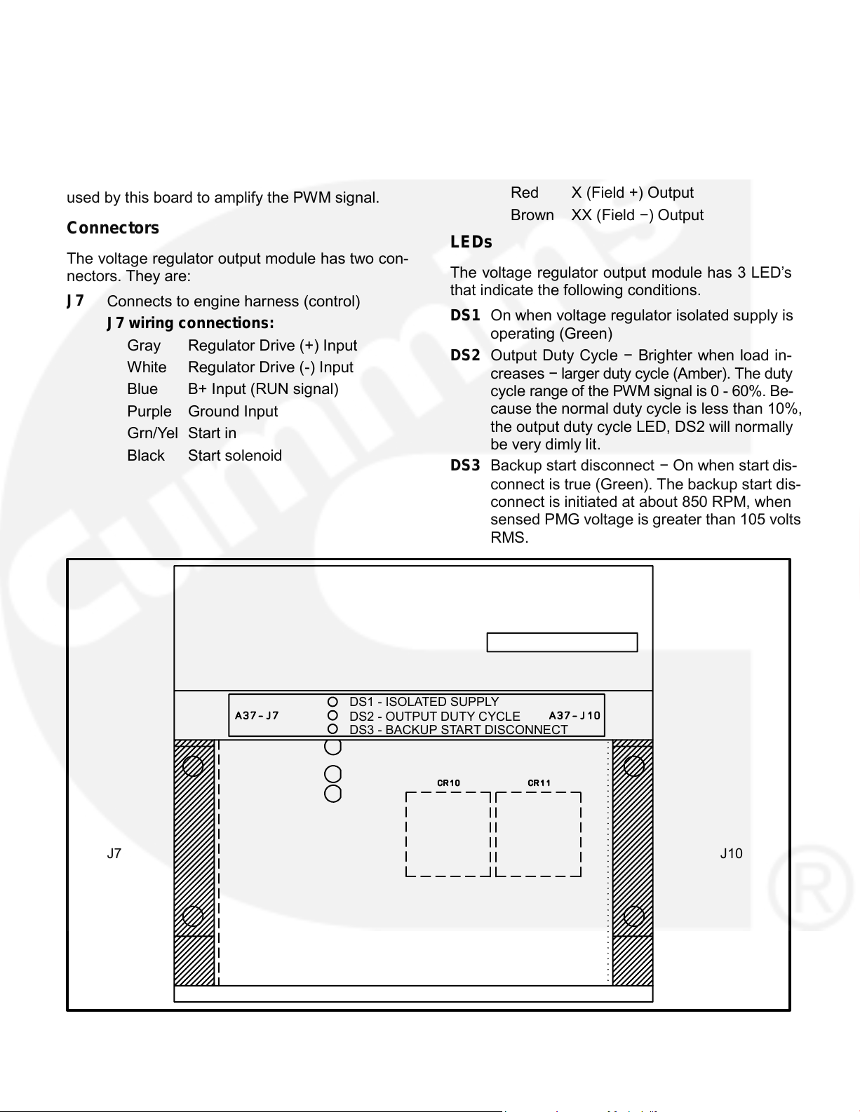
VOLTAGE REGULATOR OUTPUT MODULE
J10 Connects to engine harness (power)
(A37)
J10 wiring connections:
Green Phase A PMG power
The voltage regulator output module (Figure 3-9) is
a power amplifier. This board is used to amplify the
Yellow Phase B PMG power
pulse-width modulated (PWM) signal from the PCC
Orange Phase C PMG power
to drive the exciter windings. Power from the PMG is
Red
X (Field +) Output
used by this board to amplify the PWM signal.
Brown XX (Field −) Output
Connectors
LEDs
The voltage regulator output module has two con-
The voltage regulator output module has 3 LED’s
nectors. They are:
that indicate the following conditions.
J7
Connects to engine harness (control)
DS1 On when voltage regulator isolated supply is
J7 wiring connections:
operating (Green)
Gray
Regulator Drive (+) Input
DS2 Output Duty Cycle − Brighter when load in-
White Regulator Drive (-) Input
creases − larger duty cycle (Amber). The duty
Blue
B+ Input (RUN signal)
cycle range of the PWM signal is 0 - 60%. Be-
cause the normal duty cycle is less than 10%,
Purple Ground Input
the output duty cycle LED, DS2 will normally
Grn/Yel Start in
be very dimly lit.
Black
Start solenoid
DS3 Backup start disconnect − On when start dis-
connect is true (Green). The backup start dis-
connect is initiated at about 850 RPM, when
sensed PMG voltage is greater than 105 volts
RMS.
DS1 - ISOLATED SUPPLY
DS2 - OUTPUT DUTY CYCLE
DS3 - BACKUP START DISCONNECT
J7
J10
FIGURE 3-9. VOLTAGE REGULATOR OUTPUT MODULE (A37)
3-11
Page 29
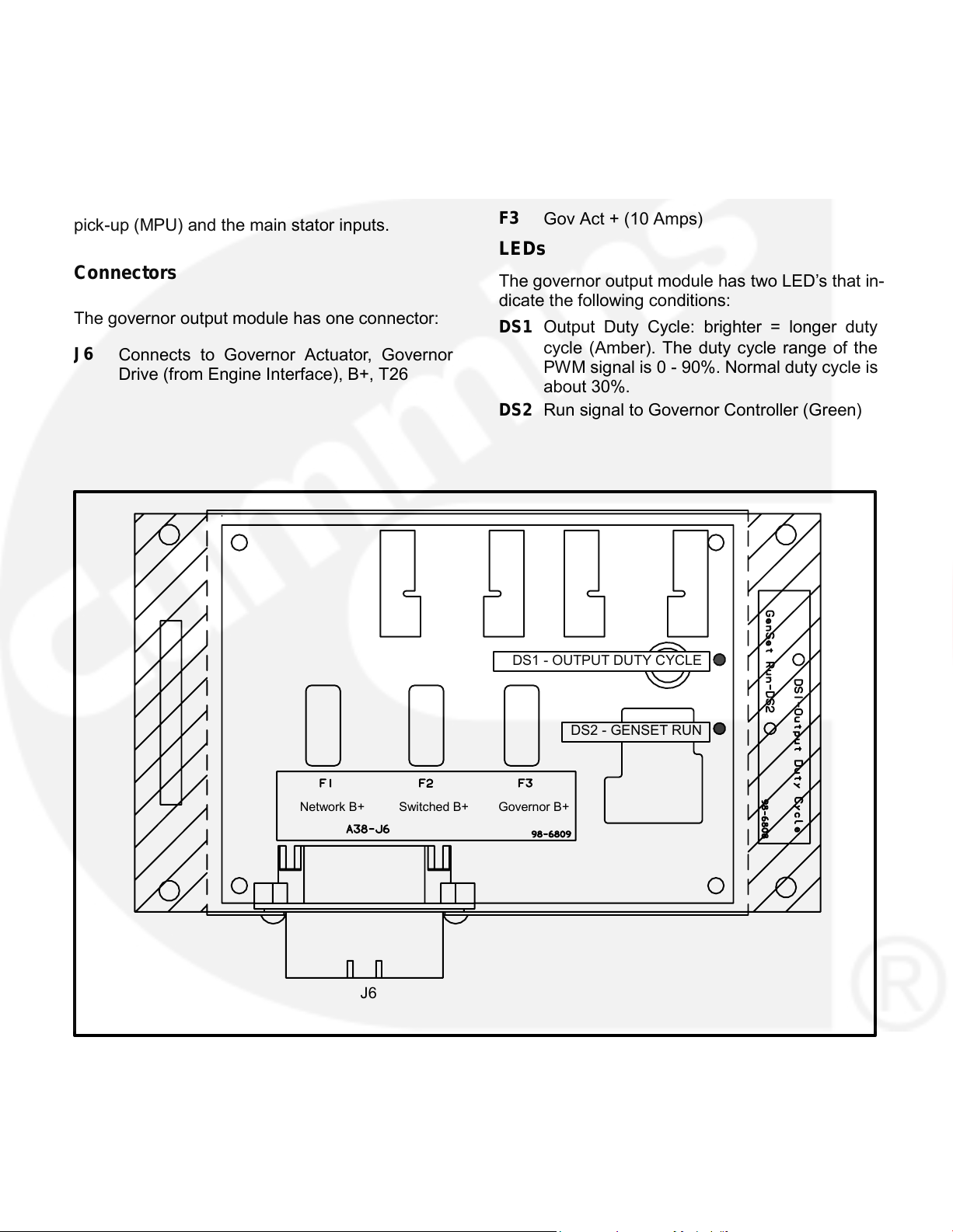
GOVERNOR OUTPUT MODULE (A38)
Fuses
The governor output module has three fuses to pro-
The governor output module (Figure 3-10) receives
tect it from overloads and groundfaults. They are:
a low power pulse−width modulated (PWM) signal
from the engine interface board and then sends an
F1
Network B+ (10 Amps)
amplified signal to drive the governor actuator. The
F2
Switched B+ (10 Amps) — T26
PCC monitors frequency from both the magnetic
F3
Gov Act + (10 Amps)
pick-up (MPU) and the main stator inputs.
LEDs
Connectors
The governor output module has two LED’s that in-
dicate the following conditions:
The governor output module has one connector:
DS1 Output Duty Cycle: brighter = longer duty
cycle (Amber). The duty cycle range of the
J6
Connects to Governor Actuator, Governor
PWM signal is 0 - 90%. Normal duty cycle is
Drive (from Engine Interface), B+, T26
about 30%.
DS2 Run signal to Governor Controller (Green)
DS1 - OUTPUT DUTY CYCLE
DS2 - GENSET RUN
Network B+
J6
FIGURE 3-10. GOVERNOR OUTPUT MODULE (A38)
3-12
Switched B+ Governor B+
Page 30
4. Troubleshooting
GENERAL
•
Tables 4-4 through 4-29: Provide detailed
troubleshooting procedures.
The PowerCommand Control continuously moni-
Table 4-30: Describes the analog circuit board
tors engine sensors for abnormal conditions, such
inputs and outputs.
as low oil pressure and high coolant temperature. If
any of these conditions occur, the PCC will light a
Table 4-31: Describes the location and func-
yellow Warning lamp or a red Shutdown lamp and
tion of each fuse.
display a message on the digital display panel.
SAFETY CONSIDERATIONS
In the event of a shutdown fault (red Shutdown
High voltages are present when the set is running.
lamp), the PCC will stop the engine and close a set
Do not open the generator output box while the set
of contacts that can be wired to trip a circuit breaker.
is running.
If the generator set is stopped for this reason, the
operator can restart the set after making adjust-
WARNING Contacting high voltage compo-
ments or corrections.
nents can cause electrocution, resulting in se-
vere personal injury or death. Keep the output
This section contains the following information:
box covers in place during troubleshooting.
When troubleshooting a set that is shut down, make
• Table 4-1: Contains a list of all status codes, in-
certain the generator set cannot be accidentally re-
cluding the displayed message and status indi-
started. Place the Run/Off/Auto switch in the Off
cator. Also references the page number that
position. Turn off or remove AC power from the bat-
contains a description of each code.
tery charger, MAKE CERTAIN EXPLOSIVE BAT-
TERY GASSES ARE DISPELLED FROM BAT-
Table 4-2: Describes each warning and shut-
TERY COMPARTMENT, and then remove the neg-
down code, warning and shutdown limits
where applicable, and basic corrective actions,
ative (−) battery cable from the set starting battery.
such as, checking fluid levels, control reset
WARNING Accidental starting of the generator
functions, battery connections, etc.
set during troubleshooting can cause severe
personal injury or death. Disable the generator
• Table 4-3: Lists the PCC oil pressure warning
set (see above) before troubleshooting.
and shutdown limits.
4-1
•
•
•
Page 31

STATUS INDICATORS
Emergency Stop shutdown status (Code 102) can be
reset only at the PCC front panel.
Non-Automatic Status Indicator: This red lamp
Digital Display: This two-line, 16-character per line
flashes continuously when the Run/Off/Auto switch
alphanumeric display is used in the menu-driven
is in the Off position.
operating system and to show shutdown and warn-
Warning Status Indicator: This yellow lamp is lit
ing messages. Refer to Tables 4-1 and 4-2.
whenever the control detects a warning condition.
After the condition is corrected, warning indicators
RESETTING THE CONTROL
can be reset by pressing the Reset switch. (It is not
necessary to stop the generator set.) In auto mode,
Press the momentary Reset Switch to reset warn-
warning indicators can also be reset by cycling the
ing and shutdown messages after the condition has
remote reset input after the condition is corrected.
been corrected. To reset a shutdown message with
the Reset switch, the Run/Off/Auto switch must be
Shutdown Status Indicator: This red lamp is lit
in the Off Position. (The control cannot go into
whenever the control detects a shutdown condition.
Standby [sleep] mode until all faults have been
Shutdown faults are latched. After the condition is
reset.)
corrected, shutdown indicators can be reset by
turning the Run/Off/Auto switch to the Off position,
In Auto mode, warning indicators can also be reset
and pressing the Reset switch. In the Auto position,
by cycling the remote reset input after the condition
shutdown faults can be reset by removing the re-
is corrected. Shutdown faults can be reset by re-
mote start input and then cycling the remote reset
moving the remote start input and then cycling the
input.
remote reset input.
WARNING AND
RESET
ALPHANUMERIC
SHUTDOWN
SWITCH
FAULT MESSAGE
STATUS INDICATORS
DISPLAY
FIGURE 4-1. CONTROL PANEL
4-2
Page 32

TABL E 4-1. WARNING AND SHUTDOWN CODES
BASIC
TROUBLE-
CODE . . . MESSAGE . . . . . . . . . . . . . . . . . . STATUS LED . . . . . . . . . CHECKS . . . SHOOTING
101 . . . . . . IDLE MODE . . . . . . . . . . . . . . . . Warning . . . . . . . . . . . . . . . . 4-4
102 . . . . . . EMERGENCY STOP . . . . . . . . . Shutdown . . . . . . . . . . . . . . . 4-4
200 . . . . . . LOW OIL PRESSURE . . . . . . . . Warning . . . . . . . . . . . . . . . . 4-4 . . . . . . . . 4-22
201 . . . . . . LOW OIL PRESSURE . . . . . . . . Shutdown . . . . . . . . . . . . . . . 4-4 . . . . . . . . 4-22
204 . . . . . . OIL PRES SENDER . . . . . . . . . Warning . . . . . . . . . . . . . . . . 4-4 . . . . . . . . 4-23
210 . . . . . . LOW COOLANT TEMP . . . . . . . Warning . . . . . . . . . . . . . . . . 4-5 . . . . . . . . 4-24
211 . . . . . . HIGH COOLANT TEMP . . . . . . Warning . . . . . . . . . . . . . . . . 4-5 . . . . . . . . 4-25
212 . . . . . . HIGH COOLANT TEMP . . . . . . Shutdown . . . . . . . . . . . . . . . 4-5 . . . . . . . . 4-25
213 . . . . . . COOLANT SENDER . . . . . . . . . Warning . . . . . . . . . . . . . . . . 4-5 . . . . . . . . 4-23
214 . . . . . . LOW COOLANT LVL . . . . . . . . . Warning . . . . . . . . . . . . . . . . 4-6 . . . . . . . . 4-26
215 . . . . . . LOW COOLANT LVL . . . . . . . . . Shutdown . . . . . . . . . . . . . . . 4-6 . . . . . . . . 4-26
220 . . . . . . MAG PICKUP . . . . . . . . . . . . . . . Shutdown . . . . . . . . . . . . . . . 4-6 . . . . . . . . 4-27
221 . . . . . . FAIL TO CRANK . . . . . . . . . . . . . Shutdown . . . . . . . . . . . . . . . 4-6 . . . . . . . . 4-13, 4-21
222 . . . . . . OVERCRANK . . . . . . . . . . . . . . . Shutdown . . . . . . . . . . . . . . . 4-6 . . . . . . . . 4-19
223 . . . . . . OVERSPEED . . . . . . . . . . . . . . . Shutdown . . . . . . . . . . . . . . . 4-6 . . . . . . . . 4-28
230 . . . . . . LOW DC VOLTAGE . . . . . . . . . . Warning . . . . . . . . . . . . . . . . 4-6 . . . . . . . . 4-29
231 . . . . . . HIGH DC VOLTAGE . . . . . . . . . Warning . . . . . . . . . . . . . . . . 4-7 . . . . . . . . 4-29
232 . . . . . . WEAK BATTERY . . . . . . . . . . . . Warning . . . . . . . . . . . . . . . . 4-7 . . . . . . . . 4-29
240 . . . . . . LOW FUEL − DAY . . . . . . . . . . . Warning . . . . . . . . . . . . . . . . 4-7 . . . . . . . . 4-30
241 . . . . . . LOW FUEL . . . . . . . . . . . . . . . . . Warning . . . . . . . . . . . . . . . . 4-7 . . . . . . . . 4-31
250 . . . . . . EEPROM ERROR . . . . . . . . . . . Shutdown . . . . . . . . . . . . . . . 4-7 . . . . . . . . 4-32
251 . . . . . . EEPROM ERROR . . . . . . . . . . . Warning . . . . . . . . . . . . . . . . 4-7 . . . . . . . . 4-32
252 . . . . . . EEPROM ERROR . . . . . . . . . . . Warning . . . . . . . . . . . . . . . . 4-7 . . . . . . . . 4-32
260 . . . . . . CUSTOMER FAULT 1* . . . . . . . Warning/Shutdown . . . . . . . 4-7/8 . . . . . . . 4-33
261 . . . . . . GROUND FAULT* . . . . . . . . . . . Warning/Shutdown . . . . . . . 4-7/8 . . . . . . . 4-33
262 . . . . . . RUPTURE BASIN* . . . . . . . . . . . Warning/Shutdown . . . . . . . 4-7/8 . . . . . . . 4-33
263 . . . . . . HIGH GEN TEMP* . . . . . . . . . . . Warning/Shutdown . . . . . . . 4-7/8 . . . . . . . 4-33
301 . . . . . . HIGH AC VOLTAGE . . . . . . . . . Shutdown . . . . . . . . . . . . . . . 4-8 . . . . . . . . 4-34
303 . . . . . . LOW AC VOLTAGE . . . . . . . . . . Shutdown . . . . . . . . . . . . . . . 4-8 . . . . . . . . 4-37
313 . . . . . . UNDER FREQUENCY . . . . . . . Shutdown . . . . . . . . . . . . . . . 4-8 . . . . . . . . 4-39
320 . . . . . . OVERCURRENT . . . . . . . . . . . . Warning . . . . . . . . . . . . . . . . 4-8 . . . . . . . . 4-40
321 . . . . . . OVERCURRENT . . . . . . . . . . . . Shutdown . . . . . . . . . . . . . . . 4-8 . . . . . . . . 4-40
322 . . . . . . SHORT CIRCUIT . . . . . . . . . . . . Shutdown . . . . . . . . . . . . . . . 4-8 . . . . . . . . 4-40
330 . . . . . . OVERLOAD . . . . . . . . . . . . . . . . Warning . . . . . . . . . . . . . . . . 4-9 . . . . . . . . 4-40
335 . . . . . . REVERSE POWER . . . . . . . . . . Shutdown . . . . . . . . . . . . . . . 4-9
* Default message. Editable for customer site requirements.
4-3
Page 33

TABLE 4-2. WARNING AND SHUTDOWN CODES
WARNING Many troubleshooting procedures present hazards which can result in severe per-
sonal injury or death. Only qualified service personnel with knowledge of fuels, electricity, and
mechanical hazards should perform service procedures. Review safety precautions.
SYMPTOM
CORRECTIVE ACTION
MESSAGE:
Indicates that the engine is operating in idle mode. When the set is operat-
IDLE MODE
ing in the RUN mode, grounding the engine idle input causes generator
101 − WARNING
build-up to be inhibited and the engine to be governed at 800 RPM. When
ground is removed from this input, the set returns to normal speed and
voltage.When the engine idle function is enabled, the control automatical-
ly sets lower oil pressure warning and shutdown trip points to reflect the
lower operating speed. When the engine idle function is removed and the
set reverts to normal operating speed, the control automatically resets oil
pressure warning and shutdown trip points to the normal settings.
Shutdown lamp lights.
Indicates local or remote Emergency Stop.
MESSAGE:
To reset the local/remote Emergency Stop button:
EMERGENCY STOP
Turn the switch clockwise and allow it to pop out (local only).
102 − SHUTDOWN
Move the Run/Off/Auto switch to Off.
Press the Reset switch.
Select Run or Auto, as required.
Warning lamp lights.
Indicates engine oil pressure has dropped to an unacceptable lev-
MESSAGE:
el. If generator is powering critical loads and cannot be shut down,
LOW OIL PRESSURE
wait until next shutdown period and then follow 201-SHUTDOWN
200 − WARNING
procedure.
To check oil pressure, access the Oil Pressure menu prior to clear-
ing the fault.
Shutdown lamp lights.
Indicates engine oil pressure has dropped below the shutdown trip point.
MESSAGE:
Check oil level, lines and filters. If oil system is OK but oil level is low, re-
LOW OIL PRESSURE
plenish. Reset control and restart. Oil pressure limits are listed in Table
201 − SHUTDOWN
4-3.
Warning lamp lights.
Indicates that the control has sensed that the engine oil pressure sender is
MESSAGE:
out of its working range. Check that the engine oil pressure sender is prop-
OIL PRES SENDER
erly connected.
204 − WARNING
4-4
Page 34

TABLE 4-2. WARNING AND SHUTDOWN CODES (CONT.)
WARNING Many troubleshooting procedures present hazards which can result in severe per-
sonal injury or death. Only qualified service personnel with knowledge of fuels, electricity, and
mechanical hazards should perform service procedures. Review safety precautions.
SYMPTOM
CORRECTIVE ACTION
Warning lamp lights.
Indicates engine coolant heater is not operating or is not circulating cool-
MESSAGE:
ant. Check for the following conditions:
LOW COOLANT TEMP
a. Coolant heater not connected to power supply. Check for blown fuse
210 − WARNING
or disconnected heater cord and correct as required.
Set is not operating. Warning occurs
b. Check for low coolant level and replenish if required. Look for pos-
when engine coolant temperature is
sible coolant leakage points and repair as required.
70° F (21° C) or lower
.
c. Open heater element. Check current draw of heater.
NOTE: In applications where the
ambient temperature falls below
may be indicated even though the
coolant heaters are operating.
Warning lamp lights.
Indicates the engine coolant temperature is getting close to the recom-
MESSAGE:
mended maximum temperature limit:
HIGH COOLANT TEMP
215
F (102° C) − standby or 207° F (97° C) − primary.
211 − WARNING
If generator is powering non-critical and critical loads and cannot be shut
down, use the following:
a. Reduce load if possible by turning off non-critical loads.
b. Check air inlets and outlets and remove any obstructions to airflow.
If engine can be stopped, follow HIGH COOLANT TEMP 212 − SHUT-
DOWN procedure.
To check coolant temperature, access the coolant temperature
menu prior to clearing the fault.
Shutdown lamp lights.
Indicates engine has overheated (coolant temperature has risen above
MESSAGE:
the shutdown trip point:
HIGH COOLANT TEMP
215
F (102° C) − standby or 207° F (97° C) − primary. Allow engine to
212 − SHUTDOWN
cool down completely before proceeding with the following checks:
a. Check for obstructions to cooling airflow and correct as necessary.
b. Check fan belt and repair or tighten if necessary.
c. Check coolant mixture.
d. Check blower fan and circulation pumps on remote radiator installa-
tions.
e. Reset control and restart after locating and correcting problem.
Warning lamp lights.
Indicates that the resistance of the coolant temperature sender is out of
MESSAGE:
range. Check the resistance of the sender. Resistance should be 500 to
COOLANT SENDER
2k ohms.
213 − WARNING
4-5
40°F (4°C), Low Coolant Temp
°
°
Page 35

TABLE 4-2. WARNING AND SHUTDOWN CODES (CONT.)
WARNING Many troubleshooting procedures present hazards which can result in severe per-
sonal injury or death. Only qualified service personnel with knowledge of fuels, electricity, and
mechanical hazards should perform service procedures. Review safety precautions.
SYMPTOM
CORRECTIVE ACTION
Shutdown lamp lights.
Indicates engine coolant level has fallen below the trip point. Allow engine
MESSAGE:
to cool down completely before proceeding.
LOW COOLANT LVL
a. Check coolant level in both radiator and coolant recovery bottle and
214 − WARNING
replenish if low. Look for possible coolant leakage points and repair if
or
necessary.
LOW COOLANT LVL
b. Reset control and restart after locating and correcting problem.
215 − SHUTDOWN
LOW COOLANT LVL Shutdown will not occur if genset is in Idle
mode (low coolant warning only ).
Shutdown lamp lights.
Indicates mag pickup speed indication is not being sensed or does not
MESSAGE:
match generator set output frequency.
MAG PICKUP
a. Restart and check RPM on the digital display.
220 − SHUTDOWN
Engine will not crank.
Indicates possible fault with control or starting system. Check for the fol-
Shutdown lamp lights.
lowing conditions:
MESSAGE:
a. Check fuse F3 on the Engine Interface board.
FAIL TO CRANK
b. Poor battery cable connections. Clean the battery cable terminals
221 − SHUTDOWN
and tighten all connections.
c. Discharged or defective battery. Recharge or replace the battery.
Shutdown lamp lights.
Indicates possible fuel system problem.
Engine stops cranking.
a. Check for empty fuel tank, fuel leaks, or plugged fuel lines and cor-
MESSAGE:
rect as required.
OVERCRANK
b. Check for dirty fuel filter and replace if necessary.
222 − SHUTDOWN
c. Check for dirty or plugged air filter and replace if necessary.
d. Reset the control and restart after correcting the problem.
Engine runs and then shuts down.
Indicates engine has exceeded normal operating speed. (115% ±1% of
Shutdown lamp lights.
nominal).
MESSAGE:
OVERSPEED
223 − SHUTDOWN
4-6
Page 36

TABLE 4-2. WARNING AND SHUTDOWN CODES (CONT.)
WARNING Many troubleshooting procedures present hazards which can result in severe per-
sonal injury or death. Only qualified service personnel with knowledge of fuels, electricity, and
mechanical hazards should perform service procedures. Review safety precautions.
SYMPTOM
CORRECTIVE ACTION
Warning lamp lights.
Indicates battery voltage is below 10 VDC.
MESSAGE:
a. Discharged or defective battery.
LOW DC VOLTAGE
Check the battery charger fuse.
230 − WARNING
Recharge or replace the battery.
b. Poor battery cable connections. Clean the battery cable terminals
and tighten all connections.
c. Check engine DC alternator. Replace engine DC alternator if normal
battery charging voltage is not obtained.
d. Check float level if applicable (raise float level).
Warning lamp lights.
Indicates battery voltage exceeds 32 VDC.
MESSAGE:
Check float level on battery charger if applicable (lower float level).
HIGH DC VOLTAGE
231 − WARNING
Check engine DC alternator. Replace engine DC alternator if normal bat-
tery charging voltage is not obtained.
Warning lamp lights.
Indicates battery voltage drops below 60% of nominal for two seconds,
MESSAGE:
during starting.
WEAK BATTERY
Discharged or defective battery.
232 − WARNING
See Warning message 230, LOW DC VOLTAGE.
Warning lamp lights.
Indicates day tank fuel supply is running low. Check fuel supply and re-
MESSAGE:
plenish as required.
LOW FUEL−DAY
240 − WARNING
or
LOW FUEL
241 − WARNING
Shutdown lamp lights.
Indicates PCC memory error. Data corruption of critical operating param-
MESSAGE:
eters.
EEPROM ERROR
250 − SHUTDOWN
Warning lamp lights.
Indicates PCC memory error. Data corruption of noncritical operating pa-
MESSAGE:
rameters.
EEPROM ERROR
251 − WARNING
or
252 − WARNING
4-7
Page 37

TABLE 4-2. WARNING AND SHUTDOWN CODES (CONT.)
WARNING Many troubleshooting procedures present hazards which can result in severe per-
sonal injury or death. Only qualified service personnel with knowledge of fuels, electricity, and
mechanical hazards should perform service procedures. Review safety precautions.
SYMPTOM
CORRECTIVE ACTION
Shutdown lamp lights.
When any one of these customer defined inputs is closed to ground, the
MESSAGE:
corresponding fault message is displayed. The nature of the fault is an op-
CUSTOMER FAULT 1
tional customer selection. These fault functions can be programmed to
260 − SHUTDOWN
initiate a shutdown or a warning.
or
As indicated by the Shutdown lamp, a shutdown response has been pre-
GROUND FAULT
selected.
261 − SHUTDOWN
or
Note: Customer fault messages are editable. The message displayed for
RUPTURE BASIN
the code shown (260 thru 263) may have been edited and may not appear
262 − SHUTDOWN
as shown in this table.
or
HIGH GEN TEMP
263 − SHUTDOWN
Warning lamp lights.
When any one of these customer defined inputs is closed to ground, the
MESSAGE:
corresponding fault message is displayed. The nature of the fault is an op-
CUSTOMER FAULT 1
tional customer selection. These fault functions can be programmed to
260 − WARNING
initiate a shutdown or a warning.
or
As indicated by the Warning lamp, a warning response has been prese-
GROUND FAULT
lected.
261 − WARNING
or
Note: Customer fault messages are editable. The message displayed for
RUPTURE BASIN
the code shown (260 thru 263) may have been edited and may not appear
262 − WARNING
as shown in this table.
or
HIGH GEN TEMP
263 − WARNING
Shutdown lamp lights.
Indicates that one or more of the phase voltages has exceeded 130% of
MESSAGE:
nominal, or has exceeded 110% of nominal for 10 seconds.
HIGH AC VOLTAGE
301 − SHUTDOWN
Shutdown lamp lights.
Indicates that one or more of the phase voltages has dropped below 85%
MESSAGE:
of nominal for 10 seconds.
LOW AC VOLTAGE
303 − SHUTDOWN
Shutdown lamp lights.
Indicates that engine speed has dropped below 90% of nominal for 10
MESSAGE:
seconds.
UNDER FREQUENCY
Note: Five seconds before shutdown, a Load Dump signal is initiated.
313 − SHUTDOWN
Check fuel supply, intake air supply and load.
4-8
Page 38

TABLE 4-2. WARNING AND SHUTDOWN CODES (CONT.)
WARNING Many troubleshooting procedures present hazards which can result in severe per-
sonal injury or death. Only qualified service personnel with knowledge of fuels, electricity, and
mechanical hazards should perform service procedures. Review safety precautions.
SYMPTOM
CORRECTIVE ACTION
Warning lamp lights.
Indicates that generator output current has exceeded 110% of rated for 60
MESSAGE:
seconds.
OVERCURRENT
Check load and load lead connections.
320 − WARNING
Shutdown lamp lights.
Indicates that generator output current has exceeded 110% of rated, and
MESSAGE:
that a PCC time/current calculation has initiated an overcurrent shut-
OVERCURRENT
down.
321 − SHUTDOWN
Check load and load lead connections.
Shutdown lamp lights.
Indicates that generator output current has exceeded 175% of rated.
MESSAGE:
Check load and load lead connections.
SHORT CIRCUIT
322 − SHUTDOWN
Warning lamp lights.
Indicates that three-phase power output exceeds 105% of standby (or
MESSAGE:
115% of prime) rating. After five seconds, the Load Dump output is acti-
OVERLOAD
vated. After 60 seconds, the OVERLOAD warning is activated.
330 − WARNING
Check load and load lead connections.
Shutdown lamp lights.
Indicates improper CT or PT phasing. (Non-parallel units only.)
MESSAGE:
Check CT / PT wiring. Refer to CT Installation in Section 5.
REVERSE POWER
335 − SHUTDOWN
4-9
Page 39

TABL E 4-3. PCC OIL PRESSURE WARNING & SHUTDOWN LIMITS
L10/M11 Engine: NORM 30-50 psi (207-345 kPa), IDLE 15 psi (103 kPa)
20 psi (138 kPa) shutdown limit - run mode value
25 psi (172 kPa) warning limit - run mode value
8 psi
(55 kPa)
shutdown limit - idle mode value
12 psi (83 kPa)
warning limit- idle mode value
NTA 855 Engine: NORM 35-50 psi (241-345 kPa), IDLE 15 psi (103 kPa)
25 psi (172 kPa) shutdown limit - run mode value
30 psi (207 kPa) warning limit - run mode value
8 psi
(55 kPa)
shutdown limit - idle mode value
12 psi (83 kPa)
warning limit- idle mode value
K19 Engine: NORM 50-70 psi (345-482 kPa), IDLE 20 psi (138 kPa)
35 psi (241 kPa) shutdown limit - run mode value
40 psi (276 kPa) warning limit - run mode value
10 psi (69 kPa)
shutdown limit - idle mode value
15 psi (103 kPa) warning limit- idle mode value
V28 Engine: NORM 50-90 psi (345-620 kPa), IDLE 20 psi (138 kPa)
35 psi (241 kPa) shutdown limit - run mode value
40 psi (276 kPa) warning limit - run mode value
10 psi (69 kPa)
shutdown limit - idle mode value
15 psi (103 kPa) warning limit- idle mode value
K38 Engine: NORM 45-65 psi (310-448 kPa), IDLE 20 psi (138 kPa)
35 psi (241 kPa) shutdown limit - run mode value
40 psi (276 kPa) warning limit - run mode value
10 psi (69 kPa)
shutdown limit - idle mode value
15 psi (103 kPa) warning limit- idle mode value
K50 Engine: NORM 50-70 psi (345-482 kPa), IDLE 20 psi (138 kPa)
35 psi (241 kPa) shutdown limit - run mode value
40 psi (276 kPa) warning limit - run mode value
10 psi (69 kPa)
shutdown limit - idle mode value
15 psi (103 kPa) warning limit- idle mode value
To check oil pressure or engine temperature during a warning, access the oil pressure
or engine temperature menu prior to clearing the fault.
4-10
Page 40

TROUBLESHOOTING PROCEDURE
LED and switch locations for each circuit board and
module are provided in Section 3. The control wiring
The following tables are a guide to help you evalu-
and circuit board connections are shown in Section
ate problems with the generator set. You can save
9.
time if you read through the manual ahead of time
and understand the system.
CAUTION
Always set the Run/Off/Auto (S12)
switch to the Off position and the Power On/
To determine the appropriate troubleshooting pro-
Standby (S5) switch to the Standby position be-
cedure for the specific problem at hand, be sure to
fore disconnecting or connecting harness con-
refer to the “Indicators” column provided in each
troubleshooting table.
nectors. Otherwise, disconnecting the harness
connectors can result in voltage spikes high
Try to think through the problem. Go over what was
enough to damage the DC control circuits of the
done during the last service call. The problem could
set.
be as simple as a loose wire, an opened fuse or a
tripped circuit breaker. (Table 4-31 describes the
Electrostatic discharge will damage
location and function of each fuse.)
circuit boards. Always wear a wrist strap when
handling circuit boards or socket-mounted IC’s
Figure 4-2 shows the location of the components
and when disconnecting or connecting harness
within the control panel that are referenced in the
connectors.
following troubleshooting procedures. Connector,
4-11
CAUTION
Page 41

S5 POWER ON/
STANDBY SWITCH
DIGITAL BOARD
A32
DISPLAY
BOARD
ANALOG
A35
BOARD
A33
ENGINE INTERFACE
CUSTOMER
A31
INTERFACE
A34
RUN/OFF/AUTO
SWITCH S12
OPTIONAL
THERMISTOR
GOVERNOR
RELAY 160°/140° C
OUTPUT MODULE
A38
TB1-1
OPTIONAL
COMMON ALARM
OPTIONAL RUN
RELAY K14
RELAYS K11, K12 &
K13
TB1-40
PT/CT BOARD A36
OPTIONAL RTD
VOLTAGE
RELAY
REGULATOR
OUTPUT MODULE
A37
ACCESSORY
BOX
FIGURE 4-2. CIRCUIT BOARD LOCATIONS
4-12
Page 42

TABL E 4-4. ENGINE DOES NOT CRANK—LOCAL OR REMOTE RUN
WARNING Many troubleshooting procedures present hazards that can result in severe personal inju-
ry or death. Only qualified service personnel with knowledge of fuels, electricity, and machinery haz-
ards should perform service procedures. Review safety precautions on pages iii and iv.
Indicator(s)
Possible Cause
Corrective Action
1. Insufficient battery voltage. Check the
1a. Recharge or replace the battery. Specific gravi-
“FAIL TO
following conditions:
ty for a fully charged battery is approximately
CRANK”
1.260 at 80° F (27° C).
a. Batteries not charged.
(221)
1b. Clean and tighten or replace the battery cable
b. Battery connections loose or dirty.
message
connectors and cables at the battery and the
c. Insufficient battery charging volt-
set.
Reset and
age.
attempt to
1c. Adjust charge rate of battery charging circuit.
d. Engine DC alternator could be bad.
start:
1d. Replace engine DC alternator if normal battery
charging voltage is not obtained.
Start LED
DS11 on the
2. Starter could be bad.
2. Reset the control. Attempt to start, and test for
engine
B+ at the starter. If there is B+ at the starter, the
interface board
starter could be bad. Test starter (see engine
turns on.
service manual). Replace the starter.
3. If there is no B+ at the starter, start so-
3. Reset the control. Attempt to start, and test for
NOTE:
lenoid K4 could be bad.
B+ into and out of start solenoid contacts. If
These two
there is B+ in, but not out, check for B+ at the
indications
start solenoid coil. If there is B+ at the coil,
suggest that
check ground connection. If ground connection
the PCC has
is good, the start solenoid is bad. Replace the
received a
start solenoid.
start signal
and has sent a
If there is B+ into and out of the start solenoid
start command
contacts, check for an open between the start
to the start
solenoid contacts and the starter. If there is no
output (J4-2)
B+, go to the next step.
on the engine
*4. Disconnect J7/P7 at the regulator output mod-
4. If there is no B+ at the start solenoid
interface
coil (K4), the backup start disconnect
ule. Test for continuity at A37 J7-5/J7-6. If there
board.
contacts in the regulator output mod-
is no continuity, the regulator output module is
ule (A37) could be open (indicating
bad. Replace A37.
that A37 is bad).
*5. If there is continuity at A37 J7-5/J7-6, reset the
5. If there is continuity at A37 J7-5/J7-6,
there may be an open between A37
control, attempt to start, and check for B+ at A37
and A31, an open between A37 and
P7-5.
K4, or A31 may be bad.
If there is B+ at P7-5, there may be an open be-
tween start solenoid coil (K4) and A37. If there is
no B+ at P7-5, check for B+ at J4-2 on the en-
gine interface board (A31) while attempting to
start.
If there is B+ at A31 J4-2, check for an open be-
tween A37 and A31.
If there is no B+ at A31 J4-2, (and DS11 is on)
the engine interface board is bad. Replace A31.
6. The mag pickup signal is not being
6. Refer to the mag pickup shutdown message
sensed.
(220).
*CAUTION: Wearing wrist strap, set S12 to Off and A32 S5 to Standby before connecting/disconnecting harness plugs.
4-13
Page 43

TABL E 4-5. ENGINE DOES NOT CRANK—LOCAL OR REMOTE RUN
WARNING
M any troubl eshooting procedures present hazards that can result in severe personal inju-
ry or death. Only qualified service personnel with knowledge of fuels, electricity, and machinery haz-
ards should perform service procedures. Review safety precautions on pages iii and iv.
Indicator(s)
Possible Cause
Corrective Action
*1. Install harness tool between A31 J4/P4. Reset
“FAIL TO
1. Fuse F3 on the engine interface board
CRANK”
(A31) may be open, or B+ may not be
the control. Attempt to start and check for B+ at
(221)
getting to F3.
J4-2. If no B+, remove F3 and check continuity.
message
If open, replace the fuse with one of the same
type and amp rating (5 Amps). If F3 is OK, check
Reset and
the B+ supply from the wiring harness.
attempt to
start:
2. To isolate:
2. Emergency Stop switch S13 or the
Start LED
PCC door harness may be bad.
Check for B+ at S13-1 and S13-2.
DS11 on the
If there is B+ at S13-2, but not at S13-1 (and
engine
S13 is NOT in the emergency stop position),
interface board
then S13 is bad. Replace S13.
does NOT
turn on.
and check for B+ at A31 J3-2. If there is no
B+, replace A31.
NOTE:
If there is B+ at A31 J3-2, check continuity
These two
from P3-2 to P3-6. If no continuity, repair or
indications
replace as necessary.
suggest that
the PCC has
received a
start signal
and has NOT
*3. Install harness tool between A32 J4/P4. Reset
3. Digital board (A32) may be bad.
sent a start
the control. Attempt to start, and test for ground
command to
output at A32 J4-3. If there is no ground output,
the start output
A32 is bad. Replace A32.
(J4-2) on the
engine
interface
board.
*4. If there is a ground output at A32 J4-3, and yet
4. Engine interface board (A31) may be
bad.
there is no B+ output at A31 J4-2; then A31 is
bad. Replace A31.
*CAUTION: Wearing wrist strap, set S12 to Off and A32 S5 to Standby before connecting/disconnecting harness plugs.
4-14
•
• If there is no B+ at S13-2, disconnect J3/P3,
•
Page 44

TABLE 4-6. ENGINE DOES NOT CRANK—REMOTE RUN
WARNING Many troubleshooting procedures present hazards that can result in severe personal inju-
ry or death. Only qualified service personnel with knowledge of fuels, electricity, and machinery haz-
ards should perform service procedures. Review safety precautions on pages iii and iv.
Indicator(s)
Possible Cause
Corrective Action
“FAIL TO
*1. Install harness tool between A32 J4/P4. Check
1. The Auto mode signal is not getting
CRANK”
from engine interface board A31 to
for ground output at A32 J4-18.
(221)
digital board A32, indicating that A31 is
If there is no ground output (but A31 DS5 is on)
message
bad.
engine interface board A31 is bad. Replace
DOES NOT
A31.
appear on
If there is a ground output at A31 J1-18, pro-
digital display
ceed to the next step.
−and:
Auto LED DS5
on the engine
interface board
(A31) is on −
*2. Install harness tool between A32 J4/P4. Reset
2. The Remote run signal is not getting
RMT Start
from customer interface board A34 to
the control. Attempt to remote start, and check
LED DS14 on
A32, indicating that A34 is bad.
for ground output at A32 J2-26. If no ground out-
the customer
put (but A34 DS14 is on) customer interface
interface board
board A34 is bad. Replace A34.
(A34) is on −
If there is a ground output at A32 J2-26, pro-
ceed to the next step.
NOTE:
This condition
suggests that
the PCC
processor
*3. If, when attempting remote start, there is a
3. Digital board (A32) may be bad.
(digital board
ground input at A32 J2-26, and a ground input
−A32) has
at A32 J4-18—and there is no “FAIL TO
NOT received
CRANK” message—and the set does not
or recognized
crank; A32 is bad. Replace, A32.
a remote start
start signal.
*CAUTION: Wearing wrist strap, set S12 to Off and A32 S5 to Standby before connecting/disconnecting harness plugs.
4-15
Page 45

TABL E 4-7. ENGINE DOES NOT CRANK—REMOTE RUN
WARNING Many troubleshooting procedures present hazards that can result in severe personal inju-
ry or death. Only qualified service personnel with knowledge of fuels, electricity, and machinery haz-
ards should perform service procedures. Review safety precautions on pages iii and iv.
Indicator(s)
Possible Cause
Corrective Action
“FAIL TO
The Auto mode input is not getting from the
CRANK”
Auto select switch (S12) to engine interface
(221)
board A31 (indicating that S12, A31, or the
message
harness is bad.
DOES NOT
appear on
*1. Disconnect A31 J3/P3. Check continuity to
1. S12 or the wiring harness may be bad.
digital display
ground at A31 J3-11. (J3-11 is ground out to
−and:
S12. If ground is not present, replace A31. If
Auto LED DS5
ground is present, place S12 in Auto and check
on the engine
continuity from P3-11 to P3-13. If no continuity,
interface board
isolate to switch or wiring harness. Repair as
(A31) is off −
necessary. If there is continuity, A31 may be
RMT Start
bad. Reconnect J3/P3.
LED DS14 on
the customer
interface board
*2. Install harness tool between A32 J4/P4. Check
2. Engine interface board A31 may be
(A34) is on −
bad.
the 16 volt (nominal) supply at A32 J4-16.
If the voltage is present at A32 J4-16, and
NOTE:
ground is present at A31 P3-13—and yet A31
This condition
DS5 is off; then A31 is bad. Replace A31.
suggests that
the engine
interface board
(A31) is NOT
3. Digital board A32 may be bad.
3. If there is no +16 volt supply voltage at A32
enabling the
J4-16, A32 is bad. Replace A32.
remote start
logic on the
digital board.
*CAUTION: Wearing wrist strap, set S12 to Off and A32 S5 to Standby before connecting/disconnecting harness plugs.
4-16
Page 46

TABL E 4-8. ENGINE DOES NOT CRANK—REMOTE RUN
WARNING Many troubleshooting procedures present hazards that can result in severe personal inju-
ry or death. Only qualified service personnel with knowledge of fuels, electricity, and machinery haz-
ards should perform service procedures. Review safety precautions on pages iii and iv.
Indicator(s)
Possible Cause
Corrective Action
“FAIL TO
The remote start input is not getting from the
CRANK”
remote start switch to the output of the cus-
(221)
tomer interface board (A34) indicating that
message
the switch, A34, or the harness is bad.
DOES NOT
appear on
*1. Install harness tool between A34 J1/P1. Reset
1. The remote start switch or the
digital display
the control. Attempt remote start and check for
wiring harness may be bad.
−and:
ground at A34 J1-13. If ground level is not pres-
Auto LED DS5
ent, isolate to the switch or the wiring harness
on the engine
by checking for a start signal at TB1-5. Repair
interface board
as necessary.
(A31) is on −
RMT Start
LED DS14 on
2. If ground is present at A34 J1-13—and yet A34
2. Customer interface board A34
the customer
DS14 is off, replace A34.
may be bad.
interface board
(A34) is off
NOTE:
This condition
suggests that
the remote
start input is
NOT passing
through the
customer
interface board
(A34) to
enable the
remote start
logic on the
digital board.
*CAUTION: Wearing wrist strap, set S12 to Off and A32 S5 to Standby before connecting/disconnecting harness plugs.
4-17
Page 47

TABL E 4-9. ENGINE DOES NOT CRANK—LOCAL RUN
WARNING Many troubleshooting procedures present hazards that can result in severe personal inju-
ry or death. Only qualified service personnel with knowledge of fuels, electricity, and machinery haz-
ards should perform service procedures. Review safety precautions on pages iii and iv.
Indicator(s)
Possible Cause
Corrective Action
“FAIL TO
The start input is not getting from the Run/
CRANK”
Off/ Auto select switch (S12) to A31 (indi-
(221)
cating that S12, A31, or the harness is bad.
message
DOES NOT
*1. Check continuity to ground at A31 J3-11. If
1. Run/Off/ Auto select switch S12 or the
appear on
ground is not present, replace A31. If ground is
wiring harness may be bad.
digital display
present, place S12 in Run and check continuity
−and:
from P3-11 to P3-12. If no continuity, isolate to
Run LED DS4
switch or wiring harness. Repair as necessary.
on the engine
If there is continuity, A31 may be bad.
interface board
(A31) is off−
*2. Install harness tool between A32 J4/P4. Check
2. Engine interface board A31
NOTE:
may be bad.
the 16 volt (nominal) supply at A32 J4-16.
This condition
suggests that
If the voltage is present at A32 J4-16, and
the start input
ground is present at A31 J3-12—and yet A31
is NOT getting
DS5 is off, replace A31.
from the
Run/Off/ Auto
switch (S12) to
3. Digital board A32 may be bad.
3. If there is no +16 volt supply voltage at A32
the engine
J4-16, replace A32.
interface board
(A31) to
enable the
remote start
logic on the
digital board.
*CAUTION: Wearing wrist strap, set S12 to Off and A32 S5 to Standby before connecting/disconnecting harness plugs.
4-18
Page 48

TABL E 4-10. ENGINE CRANKS BUT DOES NOT START
WARNING Many troubleshooting procedures present hazards that can result in severe personal inju-
ry or death. Only qualified service personnel with knowledge of fuels, electricity, and machinery haz-
ards should perform service procedures. Review safety precautions on pages iii and iv.
Indicator(s)
Possible Cause
Corrective Action
“OVERCRANK” Fuel supply or fuel delivery.
(222)
1. Restricted fuel supply due to:
1a. Add fuel if low. Prime the fuel system.
message
a. Fuel level below pickup tube in
1b. Open any closed shutoff valve in the fuel line
tank.
supplying the engine.
−and
b. Closed shutoff valve in supply line.
1c. Refer to engine service manual.
c. Fuel injuectors clogged.
While cranking,
1d. Bleed air from fuel system. Refer to engine ser-
d. Air in fuel system.
Run LED DS12
vice manual.
on the
2. Inspect the mechanical fuel linkage, and repair
engine interface
2. The mechanical fuel linkage could be
binding, loose, or damaged.
or replace as necessary.
board (A31)
is on.
Follow the procedure in the engine repair
manual to check the EFC for binding or dam-
and
age.
Disconnect the actuator connector, and con-
While cranking,
nect +12 VDC from the battery to the actuator.
Run LED DS2
The actuator should click upon application and
on the governor
removal of the voltage.
output module
If the actuator does not click, refer to the engine
(A38) is on.
manual.
If the actuator clicks, reconnect the wires to the ac-
NOTE:
tuator.
These
indications
3a. Reset the control. Attempt to start and check for
suggest that the
3. Fuel solenoid (K1) on the injuection
pump ot energized due to:
B+ at the K1 fuel solenoid coil on the injection
PCC has sent a
pump and at output of governor module. Check
run signal to the
a. Open in fuel solenoid circuit or de-
continuity from J6-20 and 21 to J6-19.
fuel solenoid.
fective governor module.
3b. Check wiring continuity of fuel solenoid circuit.
b. Defective fuel solenoid.
Test fuel solenoid.
Repair or replace as necessary.
4. Fuel tank solenoid not energized due
4a. Check wiring xontinuity of fuel tank solenoid cir-
to:
cuit.
a. Open in fuel solenoid circuit.
4b. Test fuel tank solenoid.
b. Defective fuel solenoid.
4c. Adjust charge rate of battery charging circuit.
4d. Replace engine DC alternator if normal battery
charging voltage (12 to 14 VDC) is not obtained.
Repair or replace as necessary.
5. Engine fuel injection or other engine
5. Service as necessary.
problem.
*CAUTION: Wearing wrist strap, set S12 to Off and A32 S5 to Standby before connecting/disconnecting harness plugs.
4-19
Page 49

TABL E 4-11. ENGINE CRANKS BUT DOES NOT START
WARNING Many troubleshooting procedures present hazards that can result in severe personal inju-
ry or death. Only qualified service personnel with knowledge of fuels, electricity, and machinery haz-
ards should perform service procedures. Review safety precautions on pages iii and iv.
Indicator(s)
Possible Cause
Corrective Action
“OVERCRANK”
The run signal is not getting through the
Reset the control. Attempt to start and check for B+
at A31 J4-1.
governor module to the fuel solenoid.
(222)
message
*1. Install harness tool between A31 J4/P4. Reset
1. The run signal is not getting out of the
−and
engine interface board (A31). A31
the control. Attempt to start and check for B+ at
may be bad.
A31 J4-1. If there is no B+ at A31 J4-1, replace
While cranking,
A31.
Run LED DS12
on the
2. There is an open between the engine
2. If there is B+ at A31 J4-1, install harness tool be-
engine interface
interface board (A31) and the gover-
tween A38 J6/P6. Check for B+ at A38 J6-19,
board (A31)
nor output module (A38).
while attempting to crank. If there is no B+ at
is on.
A38 J6-19, isolate to connectors and wiring.
Repair or replace as necessary.
and
3. The run sighnal is not getting through
3. If there is B+ at A31 J4-1, and there is B+ at A38
While cranking,
the governor output module (A38).
J6-19, check continuity from A38 J6-15 to bat-
Run LED DS2
A38 may be bad.
tery ground, if not continuity replace harness, if
on the governor
continuity, replace A38.
output module
(A38) is off.
NOTE:
This indication
suggest that the
PCC has sent a
run signal to
relay K6, but
the signal is not
getting through
to the fuel
control actuator
or fuel solenoid.
*CAUTION: Wearing wrist strap, set S12 to Off and A32 S5 to Standby before connecting/disconnecting harness plugs.
4-20
Page 50

TABL E 4-12. ENGINE CRANKS BUT DOES NOT START
WARNING Many troubleshooting procedures present hazards that can result in severe personal inju-
ry or death. Only qualified service personnel with knowledge of fuels, electricity, and machinery haz-
ards should perform service procedures. Review safety precautions on pages iii and iv.
Indicator(s)
Possible Cause
Corrective Action
*Install harness tool between A32 J4/P4. Attempt to
“OVERCRANK” The run signal from the digital board (A32)
start and check for ground signal at A32 J4−8.
(222)
is not being processed by the engine inter-
message
face board (A31).
−and
Run LED DS12
on the
1. The run signal is not getting out of the
1. If there is no ground signal at A32 J4−8, replace
engine interface
digital board (A32). A32 may be bad.
A32.
board (A31)
is off.
2. The run signal is not being processed
2. If there is a ground signal at A32 J4−8, replace
by the engine interface board (A31).
A31.
A31 may be bad.
NOTE:
These
indications
suggest that the
PCC has NOT
sent a run
signal −
(fuel solenoid
enable signal)
out to the
governor
module and the
fuel solenoid.
“FAIL TO
The mag pickup signal is not being
Refer to the mag pickup shutdown message
CRANK”
sensed.
(220).
(221)
message
NOTE:
The engine is
cranking but
shutting down
on a 221 fault.
*CAUTION: Wearing wrist strap, set S12 to Off and A32 S5 to Standby before connecting/disconnecting harness plugs.
4-21
Page 51

TABL E 4-13. LOW OIL PRESSURE WARNING (200) OR SHUTDOWN (201)
WARNING Many troubleshooting procedures present hazards that can result in severe personal inju-
ry or death. Only qualified service personnel with knowledge of fuels, electricity, and machinery haz-
ards should perform service procedures. Review safety precautions on pages iii and iv.
Indicator(s)
Possible Cause
Corrective Action
1. Low oil level. Clogged lines or filters.
1. Check oil level, lines and filters. If oil system is
“LOW OIL
OK but oil level is low, replenish. Oil pressure
PRESSURE”
limits are listed in Table 4-3.
warning
(200) or
shutdown
(201)
2a. Sender or oil pump could be bad. Or
2. Disconnect the oil pressure sender leads, and
message.
the generator set may be shutting
connect an oil pressure sender simulator to the
down on another fault.
harness.
a. If the control responds to the simulator, recon-
nect the sender, disconnect the run signal wire
at the fuel solenoid, and crank the engine.
Check the oil pressure reading on the digital
display.
•
If the display shows an acceptable oil pres-
sure, the problem may not be in the oil or oil
sensing system. The generator set may be
shutting down on another fault (out of fuel,
blown governor fuse, intermittent connec-
tor). Restart the generator set and monitor
the PCC display panel for other faults.
If the display does not show an acceptable
oil pressure, replace the sender. If the
PCC still doesn’t display an oil pressure
while cranking, the oil pump may be faulty.
Refer to the engine service manual.
*b. If the control does not respond to the simulator,
2b. Harness or PCC circuit board could be
the PCC or the harness is bad. Install harness
be bad.
tool between A31 J2/P2.
Isolate to the harness, engine inter-
Check for +5 VDC at the sender (lead marked
face board (A31), analog board (A33),
E1-B). If there is no 5 VDC at the sender
or digital board (A32).
Check for 5 VDC at A31 J5-18.
If yes, harness is bad. If no, check for 5
VDC at A31 J2-24.
If yes, A31 is bad. If no, A33 is bad.
If there is 5 VDC at the sender, use the sender
simulator to generate a signal to A31 J2-23. If
the pressure signal (.5 to 4.5 VDC) does not get
to A31 J2-23, isolate to the harness or A31. If
the pressure signal does get to A31 J2-23, refer
to the analog/digital troubleshooting procedure
(Table 4-29a/b).
*CAUTION: Wearing wrist strap, set S12 to Off and A32 S5 to Standby before connecting/disconnecting harness plugs.
4-22
•
•
•
•
Page 52

TABLE 4-14. SENDER WARNINGS (204 or 213)
WARNING Many troubleshooting procedures present hazards that can result in severe personal inju-
ry or death. Only qualified service personnel with knowledge of fuels, electricity, and machinery haz-
ards should perform service procedures. Review safety precautions on pages iii and iv.
Indicator(s)
Possible Cause
Corrective Action
“OIL
1. The sender connections could be bad.
1. Check the sender connections.
PRESSURE
SENDER”
warning
*2. Isolate to the sender, harness, engine interface
2. The sender, the harness, engine inter-
(204)
face board (A31), digital board (A32),
board (A31), analog board (A33), or digital
message.
or analog board (A33) could be faulty.
board (A32).
Disconnect the oil pressure sender leads, and
connect an oil pressure sender simulator to the
harness.
“OIL PRES SENDER” warning is displayed
after the fault condition is sensed for 10 sec-
onds.
a. If the control responds to the simulator, re-
place the sender.
*b. If the control does not respond to the simula-
tor, the PCC or the harness is bad. Install
harness tool between A31 J2/P2.
Check for +5 VDC at the sender (lead
marked E1-B). If there is no 5 VDC at the
sender
•
Check for 5 VDC at A31 J5-18.
If yes, harness is bad. If no, check for 5
VDC at A31 J2-24.
• If yes, A31 is bad. If no, A33 is bad.
If there is 5 VDC at the sender, use the send-
er simulator to generate a signal to A31
J2-23. If the pressure signal (.5 to 4.5 VDC)
does not get to A31 J2-23, isolate to the har-
ness or A31. If the pressure signal does get
to A31 J2-23, refer to the analog/digital trou-
bleshooting procedure (Table 4-29a/b).
“COOLANT
1. The sender connections could be bad.
1. Check the sender connections.
SENDER”
warning
*2. Isolate to the sender, harness, engine interface
2. The sender, the harness, engine inter-
(213)
face board (A31), digital board (A32),
board (A31), analog board (A33), or digital
message.
or analog board (A33) could be faulty.
board (A32).
Disconnect the sender, and plug in a resistive
sender simulator to isolate the fault.
a. If the control responds to the simulator, re-
place the sender.
b. If the control does not respond to the simula-
tor, refer to the high coolant temp trouble-
shooting procedure.
*CAUTION: Wearing wrist strap, set S12 to Off and A32 S5 to Standby before connecting/disconnecting harness plugs.
4-23
•
Page 53

TABLE 4-15. LOW ENGINE TEMPERATURE WARNING (210)
WARNING Many troubleshooting procedures present hazards that can result in severe personal inju-
ry or death. Only qualified service personnel with knowledge of fuels, electricity, and machinery haz-
ards should perform service procedures. Review safety precautions on pages iii and iv.
Indicator(s)
Possible Cause
Corrective Action
“LOW
DS3 / A31 is on, indicating that engine in-
Isolate the source of the signal.
COOLANT
terface board A31 is receiving a low cool-
Unplug the coolant temperature switch (S1) and re-
TEMP”
ant temp from the sender.
set the control.
warning
The sender, the harness or A31 could be
1. If the 210 warning message drops out and does
(210)
bad.
not reappear, replace the sender.
message.
*2. If the 210 warning message reappears and re-
Coolant level
mains after control reset, disconnect A31 J4
is normal.
and check continuity from P4−13 to GND.
• If there is continuity, replace the harness.
Heater is OK.
A31.
Coolant temp
on front panel
display is OK.
DS3 on the
engine
interface
board, A31,
is on.
“LOW
DS3 / A31 is off, indicating that engine in-
Isolate the source of the signal.
COOLANT
terface board A31 is not receiving a low en-
Check J4−6/P4−6 on A32.
TEMP”
gine temp signal from the sender—but the
*1. Install harness tool between A32 J4/P4.
warning
210 message indicates that A32, the digital
2. Open J4−6 and reset the control.
(210)
board, is responding to a false low engine
message.
temp signal.
If fault drops out and does not return, re-
place A31.
A31, the engine interface board, or A32,
Coolant level
the digital board, could be bad.
If fault returns after resetting the control,
is normal.
replace A32.
Heater is OK.
Coolant temp
on front panel
display is OK.
DS3 on the
engine
interface
board, A31,
is off.
*CAUTION: Wearing wrist strap, set S12 to Off and A32 S5 to Standby before connecting/disconnecting harness plugs.
4-24
• If there is no continuity, replace circuit board
•
•
Page 54

TABL E 4-16. HIGH ENGINE TEMPERATURE WARNING (211) OR SHUTDOWN (212)
WARNING
M any troubl eshooting procedures present hazards that can result in severe personal inju-
ry or death. Only qualified service personnel with knowledge of fuels, electricity, and machinery haz-
ards should perform service procedures. Review safety precautions on pages iii and iv.
Indicator(s)
Possible Cause
Corrective Action
“HIGH
1. Engine problem:
1. Refer to the engine service manual if there are
COOLANT
any physical indications of overheating.
Coolant pump could be faulty.
TEMP”
2. Correct any overload condition.
Thermostat could be faulty.
warning
3. If there are no physical indications of overheat-
There could be an obstruction in
(211) or
the coolant flow.
ing, check to see if the PCC accurately displays
shutdown
ambient engine temperature.
External coolant pump (with re-
(212)
mote radiator) could be faulty.
If the PCC ambient coolant temperature
message.
reading is accurate, the engine may be over-
External radiator fan motor (with re-
Coolant
heating. Refer to the engine service manual.
mote radiator) could be faulty.
mixture and
2. The generator set may have been
If the PCC ambient coolant temperature
level is normal.
reading is not accurate, isolate to the send-
overloaded.
er, harness, engine interface board (A31),
3. Sender, harness or PCC circuit board
No airflow
analog board, or digital board.
could be bad.
obstructions.
Disconnect the coolant temperature sender
leads, and connect a coolant temperature
Fan belt is OK.
sender simulator to the harness.
a. If the control responds to the simulator, re-
place the sender.
*b. If the control does not respond to the simu-
lator, install harness tool between A31
J5/P5. Connect the coolant temperature
sender simulator (and B+) to A31 J5.
If the control displays the correct simulated
temperature, replace the harness.
If the control does not display the correct
simulated temperature, install harness tool
at A31 J2/P2, and open lines 18/19 (and
14/15, if applicable). Check for continuity
between A31 J2-18 to 19 (for coolant temp
L), and A31 J2-14 to 15 (for coolant temp R).
If no continuity, then A31 is bad.
lated temperature signal and mea-
sure the voltage out of A31 (A31
J2-18 to 19, and A31 J2-14 to 15).
If voltage is not OK (refer to the ana-
log board inputs and outputs, Table
4-30), replace A33.
If voltage is OK, refer to the analog/
digital troubleshooting procedure
(Table 4-29a/b).
*CAUTION: Wearing wrist strap, set S12 to Off and A32 S5 to Standby before connecting/disconnecting harness plugs.
4-25
•
•
•
•
•
•
•
•
•
•
• If continuity is OK, then send a simu-
Page 55

TABL E 4-17. LOW COOLANT WARNING OR SHUTDOWN (214 / 215)
WARNING Many troubleshooting procedures present hazards that can result in severe personal inju-
ry or death. Only qualified service personnel with knowledge of fuels, electricity, and machinery haz-
ards should perform service procedures. Review safety precautions on pages iii and iv.
Indicator(s)
Possible Cause
Corrective Action
“LOW
DS2 on A31 is on, indicating that A31 is re- If the coolant level is normal, isolate the source of
COOLANT
ceiving a low coolant signal from the send- the low coolant signal. (This is a ground signal.)
LVL” warning
er.
Disconnect the signal lead at the sender and reset
(214) or
The sender, the harness or the A31 circuit the control.
shutdown
board could be bad.
1. If the 215 shutdown message drops out and
(215) message
does not reappear, replace the sender.
Coolant level
*2. If the 215 shutdown message reappears and
is normal.
remains after control reset, disconnect J4/A31
and check continuity from P4−7 to GND.
DS2 on the
•
If there is continuity, replace the harness.
engine
If there is no continuity, replace circuit board
interface
A31.
board, A31,
is on.
“LOW
DS2 on A31 is off, indicating that A31 is not If the coolant level is normal, isolate the source of
COOLANT
receiving a low coolant signal from the the low coolant signal.
LVL” warning
sender—but the 215 message indicates
(214) or
that A32, the digital board, is responding to
*1. Install harness tool between A32 J4/P4.
shutdown
a false low coolant signal.
2. Open the J4-4 circuit and reset the control.
(215) message
A31, the engine interface board, or A32, the
If the fault drops out and does not return, re-
digital board, could be bad.
Coolant level
place A31.
is normal.
replace A32.
DS2 on the
engine
interface
board, A31,
is off.
*CAUTION: Wearing wrist strap, set S12 to Off and A32 S5 to Standby before connecting/disconnecting harness plugs.
4-26
•
Check J4−4/P4−4 on A32.
•
• If the fault returns after resetting the control,
Page 56

TABL E 4-18. MAG PICKUP SHUTDOWN (220)
WARNING Many troubleshooting procedures present hazards that can result in severe personal inju-
ry or death. Only qualified service personnel with knowledge of fuels, electricity, and machinery haz-
ards should perform service procedures. Review safety precautions on pages iii and iv.
Indicator(s)
Possible Cause
Corrective Action
“MAG
This indicates that the PCC is not sensing
PICKUP”
the mag pickup signal, or the mag pickup
shutdown
frequency does not correspond (in propor-
message (220) tion) to the genset output frequency.
1. Check and correct setting if necessary.
1. The PCC may not be set for the correct
generator set.
2. Inspect the wires, and repair or replace as nec-
2. Loose or damaged mag pickup wire.
essary.
*3/4 To isolate the problem, reset the control and at-
3. Damaged mag pickup (MPU).
tempt to start the set in idle mode.
4. The harness, the engine interface
a. If the engine displays a “FAIL TO CRANK” shut-
board (A31), the analog board (A33) or
down message, or if the engine starts and idles,
the digital board (A32) could be bad.
but then shuts down on a MAG PICKUP fault,
the MPU sender could be bad. Remove the
MPU connectors and check for 3.5 to 15 VAC at
the MPU while cranking.
• If no output, check for damage or debris.
Also check for improper adjustment of the
MPU. (Refer to Section 5.) If there is still no
output, replace the MPU sender.
•
If the MPU output is OK, install harness tool
between A32 J4/P4. Check for MPU voltage
at A32 J4-10 to 11, while cranking. If OK, re-
place A32. If not OK, use continuity checks
to isolate to A31 or harness.
b. If the engine starts and idles, and does not dis-
play a fault, then there could be a frequency
mismatch problem.
digital multimeter and compare to the fre-
quency on the PCC display.
If they do match, multiply the frequency by
30 and compare this number to the RPM on
the PCC display. If these are not the same,
the MPU sender may be bad. Replace the
MPU sender
If the multimeter and PCC frequencies do
not match, there is a frequency sensing
problem. Verify the accuracy of the PCC
L1N voltage, and then refer to the analog/
digital troubleshooting procedure (Table
4-29a/b).
*CAUTION: Wearing wrist strap, set S12 to Off and A32 S5 to Standby before connecting/disconnecting harness plugs.
4-27
• Measure generator output frequency with a
•
•
Page 57

TABLE 4-19. OVERSPEED SHUTDOWN (223)
WARNING Many troubleshooting procedures present hazards that can result in severe personal inju-
ry or death. Only qualified service personnel with knowledge of fuels, electricity, and machinery haz-
ards should perform service procedures. Review safety precautions on pages iii and iv.
Indicator(s)
Possible Cause
Corrective Action
1. The mechanical fuel linkage could be
1. Inspect the mechanical fuel linkage, and repair
“OVERSPEED”
binding, loose, or damaged.
or replace as necessary.
shutdown
message (223)
• Follow the procedue in the engine repair manu-
al to check the EFC for binding or damage.
• Disconnect the actuator connector, and con-
nect +12 VDC from the battery to the actuator.
The actuator should click upon applicatin and
removal of the voltage.
If the actuator does not click, refer to the engine
manual.
If the actuator clicks, reconnect the wires to the
actuator.
*2. Reset the control, and start the set while moni-
2. The governor output module (A38) or
the digital board (A32) could be bad.
toring the PCC duty cycle display.
If the duty cycle goes high (above 40%) and the
set shuts down on overspeed, replace A32.
down on overspeed, replace A38.
*CAUTION: Wearing wrist strap, set S12 to Off and A32 S5 to Standby before connecting/disconnecting harness plugs.
4-28
•
• If the duty cycle goes to zero and the set shuts
Page 58

TABLE 4-20. DC (BATTERY) WARNINGS (230, 231, 232)
WARNING Many troubleshooting procedures present hazards that can result in severe personal inju-
ry or death. Only qualified service personnel with knowledge of fuels, electricity, and machinery haz-
ards should perform service procedures. Review safety precautions on pages iii and iv.
Indicator(s)
Possible Cause
Corrective Action
1. Weak or discharged battery.
1. Recharge or replace the battery. Specific gravi-
“LOW DC
ty for a fully charged battery is approximately
VOLTAGE”
1.260 at 80° F (27° C).
(230) or
“WEAK
2. Low electrolyte level in battery.
2. Replenish electrolyte and recharge battery.
BATTERY”
(232),
warning
3. Battery connections loose or dirty.
3. Clean and tighten or replace the battery cable
message.
connectors and cables at the battery and the
set.
4. Insufficient battery charging voltage.
4. Adjust charge rate of battery charging circuit,
according to manufacturers instructions.
5. Engine DC alternator could be bad.
5. Replace engine DC alternator if normal battery
charging voltage is not obtained.
*6. If the battery voltage, electrolyte, and connec-
6. If the batteries are OK, the problem
may be the harness, the engine inter-
tions are OK, check the battery voltage at A31
face board (A31), the digital board
J5-17. If the voltage is not OK (same as battery
(A32), or the analog board (A33).
voltage), disconnect J5 and isolate to the har-
ness or A31.
If the voltage is OK, check battery voltage at
A33 J1-31. If the voltage is not OK, replace
A31. If the voltage at A33 J1-31 is OK, isolate to
A33 or A32 using the analog input trouble-
shooting procedure (Table 4-29a/b).
“HIGH DC
1. Excessive battery charging voltage.
1. Adjust charge rate of battery charging circuit ac-
VOLTAGE”
cording to manufacturers instructions.
(231)
warning
2. Engine DC alternator could be bad.
2. Replace engine DC alternator if normal battery
message.
charging voltage is not obtained.
*3. Check the battery voltage at A31 J5-17. If the
3. If the battery voltage is OK, the prob-
But battery
lem may be the engine interface board
voltage is not OK (same as battery voltage), dis-
voltage is OK.
(A31), the digital board (A32), or the
connect J5 and isolate to the harness or A31.
analog board (A33).
If the voltage is OK, check battery voltage at
A33 J1-31. If the voltage is not OK, replace A31.
If the voltage at A33 J1-31 is OK, isolate to A33
or A32 using the analog input troubleshooting
procedure (Table 4-29a/b).
*CAUTION: Wearing wrist strap, set S12 to Off and A32 S5 to Standby before connecting/disconnecting harness plugs.
4-29
Page 59

TABL E 4-21 . LOW FUEL −DAY WARNING (240)
WARNING Many troubleshooting procedures present hazards that can result in severe personal inju-
ry or death. Only qualified service personnel with knowledge of fuels, electricity, and machinery haz-
ards should perform service procedures. Review safety precautions on pages iii and iv.
Indicator(s)
Possible Cause
Corrective Action
“LOW FUEL−
DS1 on A31 is on, indicating that A31 is re- If the fuel level is normal, isolate the source of the
DAY”
ceiving a low fuel signal from the sender.
low fuel signal.
warning
The sender, the harness or thhe A31 circuit Disconnect the signal lead at the sender and reset
message (240)
board could be bad.
the control.
1. If the 240 message drops out and does not re-
Fuel level is
appear, replace the sender.
normal.
*2. If the 240 message reappears and remains af-
DS1 on the
ter control reset, disconnect J4/A31 and check
engine
continuity from P4−14 to GND.
interface
•
If there is continuity, replace the harness.
board, A31,
If there is no continuity, replace circuit board
is on.
A31.
“LOW FUEL−
DS1 on A31 is off, indicating that the PCC is If the fuel level is normal, isolate the source of the
DAY”
not receiving a low fuel signal from the low fuel signal.
warning
sender—but the 240 message indicates
*1. Install a breakout connector at A32 J4.
message (240)
that A32, the digital board, is responding to
2. Open the J4-15 circuit and reset the control.
a false low fuel signal.
Fuel level is
If the fault drops out and does not return, re-
A31, the engine interface board, or A32,
normal.
place A31.
the digital board, could be bad.
DS1 (A31) and
go to step 3.
DS13 (A34)
*3. Install harness tool between A32 J2/P2.
are off.
4. Open the J2-19 circuit and reset the control.
If the fault drops out and does not return, re-
place A31.
If the fault returns after resetting the control,
replace A32.
*CAUTION: Wearing wrist strap, set S12 to Off and A32 S5 to Standby before connecting/disconnecting harness plugs.
4-30
•
•
• If the fault returns after resetting the control,
•
•
Page 60

TABL E 4-22 . LOW FUEL WARNING (241)
WARNING Many troubleshooting procedures present hazards that can result in severe personal inju-
ry or death. Only qualified service personnel with knowledge of fuels, electricity, and machinery haz-
ards should perform service procedures. Review safety precautions on pages iii and iv.
Indicator(s)
Possible Cause
Corrective Action
“LOW FUEL”
DS13 on A34 is on, indicating that A34 is re- If the fuel level is normal, isolate the source of the
warning
ceiving a low fuel signal from the customer low fuel signal.
message (241) circuit.
Disconnect the signal lead near the control and reset
If there is no actual fault, the problem may the control.
Fuel level is
be a short to ground in the external wiring
1. If the 241 message drops out and does not re-
normal.
or a bad customer interface board (A34)
.
appear, there is a short to ground in the external
DS13 on the
wiring or a faulty sender.
customer
*2. If the 241 message reappears and remains af-
interface
ter control reset, disconnect J1/A34 and check
board, A34, is
continuity from P1−5 to GND.
on.
ground in the external wiring.
If there is no continuity, replace circuit board
A34.
“LOW FUEL”
DS13 on A34 is off, indicating that the PCC If the fuel level is normal, isolate the source of the
warning
is not receiving a low fuel signal from the low fuel signal.
message (241)
*1. Install harness tool between A32 J2/P2.
that A32, the digital board, is responding to
2. Open the J2-19 circuit and reset the control.
Fuel level is
a false low fuel signal.
normal.
If the fault drops out and does not return, re-
A34, the customer interface board, or A32,
place A34.
DS13 (A34) is
the digital board, could be bad.
off.
replace A32.
*CAUTION: Wearing wrist strap, set S12 to Off and A32 S5 to Standby before connecting/disconnecting harness plugs.
4-31
sender—but the 241 message indicates
• If there is continuity, find and repair a short to
•
•
• If the fault returns after resetting the control,
Page 61

TABLE 4-23. EEPROM ERROR SHUTDOWN (250) OR WARNING (251, 25 2)
WARNING Many troubleshooting procedures present hazards that can result in severe personal inju-
ry or death. Only qualified service personnel with knowledge of fuels, electricity, and machinery haz-
ards should perform service procedures. Review safety precautions on pages iii and iv.
Indicator(s)
Possible Cause
Corrective Action
The EE memory on the digital board (A32)
1. Perform the initial start setup procedure.
“EEPROM
may be bad.
Turn the Run/Off/Auto switch to Off and reset
ERROR”
the control. Simultaneously press the RESET,
shutdown
MENU, and PHASE SELECT keys to start the
(250)
setup.
message.
Select the correct values, save your choices,
and attempt to start the set.
2. If the set shuts down on the same EEPROM
ERROR message, replace the digital board
(A32).
“EEPROM
The EE memory on the digital board (A32)
1. Perform the adjustment procedures (described
ERROR”
may be bad.
in Section 5). Save the adjustments.
warning
Reset the control. Shut off and restart the set.
(251)
2. If the control generates the same EEPROM
message.
ERROR message, perform the calibration pro-
cedures in Section 5.
Reset the control. Shut off and restart the set.
3. If the control generates the same EEPROM
ERROR message, replace the digital board
(A32).
“EEPROM
The EE memory on the digital board (A32)
1. If this message occurred during an adjustment,
ERROR”
may be bad.
option selection, or calibration of the PCC,
warning
verify the values or choices selected and repeat
(252)
the save operation.
message.
Reset the control. Shut off and restart the set.
2. If the control generates the same EEPROM
ERROR message, replace the digital board
(A32).
*CAUTION: Wearing wrist strap, set S12 to Off and A32 S5 to Standby before connecting/disconnecting harness plugs.
4-32
Page 62

TABL E 4-24a. CUSTOMER FAULTS (260**, 261, 262 or 263)
WARNING Many troubleshooting procedures present hazards that can result in severe personal inju-
ry or death. Only qualified service personnel with knowledge of fuels, electricity, and machinery haz-
ards should perform service procedures. Review safety precautions on pages iii and iv.
Indicator(s)
Possible Cause
Corrective Action
If the corresponding LED on the customer Isolate the source of the false signal.
“CUSTOMER
interface board (A34) is on, then A34 is re-
Disconnect the signal lead near the control and
FAULT
ceiving a signal from the customer circuit.
(260, 261, 262
reset the control.
or 263)
If there is no actual fault, the problem may
1. If the message drops out, there is a short to
message.
be a short to ground in the external wiring
ground in the external wiring.
or a bad customer interface board (A34).
2. If the message remains, replace A34.
And
corresponding
LED on
customer
interface board
A34 is on.
If the corresponding LED on the customer Isolate the source of the false signal.
“CUSTOMER
interface board (A34) is off, then A34 is not
Check J2/P2 on A32.
FAULT
receiving a signal from the customer circuit.
*
1. Install harness tool between A32 J2/P2.
(260, 261, 262
or 263)
The message indicates that A32, the digital
2. Open the appropriate circuit J2-3, J2-24, J2-9,
message.
board, is responding to a false signal.
or J2-15 and reset the control.
A34, the customer interface board, or A32,
If the fault does not return, replace A34.
And
the digital board, could be bad.
corresponding
If the fault reappears, replace A32.
LED on
customer
interface board
A 34
A32
CUSTOMER FAULT
A34 is off.
LED
CONNECTOR
FAULT #
CODE
DS4
J2-3
1
260
DS11
J2-24
2
261
DS15
J2-9
3
262
DS3
J2-15
4
263
*CAUTION: Wearing wrist strap, set S12 to Off and A32 S5 to Standby before connecting/disconnecting harness plugs.
4-33
** For generator sets with QST30 Engines, Customer Fault 260 is Rack Position Warning see page 4-34
•
•
Page 63

TABLE 4-24b. RACK POSITIONING WARNING 260 (QST30 ENGINES)
WARNING Many troubleshooting procedures present hazards that can result in severe personal inju-
ry or death. Only qualified service personnel with knowledge of fuels, electricity, and machinery haz-
ards should perform service procedures. Review safety precautions on pages iii and iv.
Indicator(s)
Possible Cause
Corrective Action
PowerCommand control fault or defective
Restart the generator set and monitor the fault
end of this section (Page 4-46).
“RACK
governor control circuitry.
POSITION ”
warning
message
(260)
4-34
*CAUTION: Wearing wrist strap, set S12 to Off and A32 S5 to Standby before connecting/disconnecting harness plugs.
LED’s of the governor output module (A38). Refer
to Section 3 for LED descriptions.
1 LED’s (DS1 through DS4 are on and DS5
and DS6 are off) do not indicate a fault,
refer to “Customer Fault 261, 262 & 263
for corrective action.
2 LED’s (DS5 or DS6 are on) one or more
indicate a fault and the generator set
shuts down after restarting – perform the
Rack Position Fault/Test Procedure at the
Page 64

TABLE 4-25a . HIGH AC VOLTAGE SHUTDOWN (301)
WARNING Many troubleshooting procedures present hazards that can result in severe personal inju-
ry or death. Only qualified service personnel with knowledge of fuels, electricity, and machinery haz-
ards should perform service procedures. Review safety precautions on pages iii and iv.
Indicator(s)
Possible Cause
Corrective Action
1. The problem may be in the PCC, the
1. Set the display on the PCC to GEN, VOLTS,
“HIGH AC
L-N.
alternator, or the interconnection be-
VOLTAGE ”
tween them.
a. Start the genset and observe the voltage
shutdown
displayed on the digital display.
(301)
Note 1: The PCC may indicate either
b. If all phases of voltage are balanced and not
message.
a low AC Voltage or High AC Voltage
zero, but lower than normal, the alternator
shutdown due to the design of the
and the input to the PCC are OK. The prob-
logic in the control.
lem is in the excitation circuit for the alterna-
tor. Go to step 2.
You must first determine if the out-
put voltage the control sees is low
c. If one or more phases of voltage are high or
or high.
the voltages are unbalanced, the PCC is not
measuring all phases of voltage and is re-
Note 2: Residual voltage is normally
sponding to the low “average” of the three
5 to 10% of nominal output voltage.
phases of voltage. Go to step 3.
For example, a genset with a 480
volt output, will have a residual volt-
age of 25 to 50 VAC at normal oper-
ating speed.
2. The problem may be the regulator
2. With DC power to the PCC and with the set not
module (A37), the engine interface
running, check A31 DS9, the AVR duty cycle
board (A31), or the digital board (A32).
LED. this LED should be off. If it si on, go to step
2d.
Isolate the genset output from the load. Discon-
nect A37 J10, and place the set in Idle mode. In
Idle mode the excitation circuit is disabled. Start
the set and monitor the AC output voltage with a
digital multimeter.
a. If output voltage is greater than residual (5%
of normal output), go to step 3.
b. If output voltage stays at 0 (or residual), and
DS2 on A37 is off, go to step 4.
c. If output voltage stays at 0 (or residual), and
DS2 on A37 is on, look at DS9 on A31.
If DS9 on A31 is off, replace A37.
d. If DS9 on A31 is on, connect a breakout con-
nector at A32 J4, and open J4-2.
If DS9 goes out, replace A32.
If DS9 stays on replace A31.
(Continued)
*CAUTION: Wearing wrist strap, set S12 to Off and A32 S5 to Standby before connecting/disconnecting harness plugs.
4-35
Page 65

TABLE 4-25b. HIGH AC VOLTAGE SHUTDOWN (301)
WARNING Many troubleshooting procedures present hazards that can result in severe personal inju-
ry or death. Only qualified service personnel with knowledge of fuels, electricity, and machinery haz-
ards should perform service procedures. Review safety precautions on pages iii and iv.
Indicator(s)
Possible Cause
Corrective Action
*3. Before starting the generator set, discon-
3. The problem may be the PT/CT mod-
“HIGH AC
ule (A36) or the interconnecting wiring
nect the harness connector from the PT/CT
VOLTAGE ”
to the PT/CT module.
module (A36) and connect the harness tool
shutdown
between A36 and its harness connector.
NOTE: To calculate the “expected A36
(301)
Check the output voltage at the alternator
output” voltage range, do the follow-
message.
output terminals and record the voltages.
ing:
a. If the voltages are not balanced, go to step 5.
Determine the ratio between the mea-
b. If the voltages are balanced, calculate the
sured voltage and the expected volt-
expected output voltage from the PT/C mod-
age. The output (18 VAC) of the PT/CT
ule (see Note to the left). Measure and re-
module will also be reduced by this ra-
cord the outputs from A36 J8 pins 6−5, 4−3,
tio.
and 2−1.
If the output voltage is proportional to the
alternator output voltage the A36 module
is OK. Go on to step 4.
If the voltages are not balanced, replace
A36.
*4. Disconnect the plugs in the following steps
4. The problem may be in the customer
interface board (A34) or the intercon-
below with the set off then start the set in the
necting wiring.
idle mode, and measure voltages with a digi-
tal multimeter.
a. Disconnect J3/P3 (blue) and insert the har-
ness tool. Check the voltage into the cus-
tomer interface board with the harness tool
at J3 terminals 4−6, 5−13, and 7−20. Re-
move the harness tool and reconnect J3 and
P3. These voltages should be the same val-
ues measured in step 3b.
If the voltages are balanced, continue in this
step. If the voltages are unbalanced, repair
the harness between the A36 module and
the A34 board.
b. Disconnect J5/P5 on the customer interface
board and insert the harness tool. Check the
voltage out of the customer interface board
at J5 terminals 24−28, 26−28, and 30−28.
These voltages should be the same values
measured in step 3b.
If the voltages are balanced, go to step 5. If
the voltages are unbalanced, replace the
customer interface board.
(Continued)
*CAUTION: Wearing wrist strap, set S12 to Off and A32 S5 to Standby before connecting/disconnecting harness plugs.
4-36
Page 66

TABLE 4-25c . HIGH AC VOLTAGE SHUTDOWN (301)
WARNING Many troubleshooting procedures present hazards that can result in severe personal inju-
ry or death. Only qualified service personnel with knowledge of fuels, electricity, and machinery haz-
ards should perform service procedures. Review safety precautions on pages iii and iv.
Indicator(s)
Possible Cause
Corrective Action
*5. Using the harness tool, check the “3-phase
5. The problem may be the analog board
“HIGH AC
(A33).
ave” signal at A33 J2-18.
VOLTAGE ”
If the voltage is within the expected range,
shutdown
replace A32. If the voltage is not within the
NOTE: To determine the “3-phase
(301)
expected range, replace A33. See Note.
ave” signal voltage range for Step 3b,
message.
use the following formula:
V
out
3-phase ave = Vin (2.9÷PT) ±5%
V
in
= Actual generator output voltage
(phase-to-neutral)
PT = PT primary (120, 240 or 346)
6. The problem may be in the generator
6. Refer to the generator servicing procedures in
set itself.
Section 6.
*CAUTION: Wearing wrist strap, set S12 to Off and A32 S5 to Standby before connecting/disconnecting harness plugs.
4-37
Page 67

TABLE 4-26a. LOW AC VOLTAGE SHUTDOWN (303)
WARNING Many troubleshooting procedures present hazards that can result in severe personal inju-
ry or death. Only qualified service personnel with knowledge of fuels, electricity, and machinery haz-
ards should perform service procedures. Review safety precautions on pages iii and iv.
Indicator(s)
Possible Cause
Corrective Action
1. If output voltage is low and both A37/DS2 and
1. PMG or field wiring could be faulty.
“LOW AC
A31/DS10 are on, check and repair the PMG or
VOLTAGE ”
field wiring.
shutdown
(303)
2. The rotating rectifier assembly (diodes
2. Check each diode according to Servicing the
message.
CR1 through CR6) is faulty.
Generator in Section 6. Service as necessary.
3. Overload.
3. Check the load and correct any overload.
4. Check connectors J8 and J9 on A36, J3 and J5
4. There may be a loose connector in the
control loop.
on A34, and J7 on A37.
*5. Isolate the genset output from the load. Reset
the control, restart the set, and measure AC
output voltage with a multimeter.
a. If output voltage is high, refer to the trouble-
5a. The problem may be the analog board
(A33) or the digital board (A32).
shooting section for High AC Voltage Shutdown
(301).
If output voltage is normal, the problem must be
in the voltage sensing circuitry (A32 or A33).
Isolate, using the analog input troubleshooting
5b. The problem may be the regulator
procedure (Table 4-29a/b). Check the phase
module (A37), the engine interface
board (A31), or the digital board (A32).
that shows a low voltage on the PCC display.
*b. If output voltage is low, the control cannot drive
the output voltage high enough. The problem
could be A37, A31, or A32. Restart the set and
monitor isolated B+ supply LED A37/DS1,
output duty cycle LED A37/DS2, and
AVR duty cycle LED A31/DS10.
•
If A37/DS1 is not on, disconnect A3 J7/P7
and check for B+ at P7-1. (Control must be in
Run mode for B+ reading.)
If B+ is OK to A37, replace A37.
If A37/DS1 is on, check A31/DS10 (with the
set running).
If A31/DS10 is not on with set running, check
for continuity: A31 J1-2 to J4-10 and A31
J1-1 to J4-11 (270 ohms). If no continuity, re-
place A31.
If A31is OK, replace A32.
If A31/DS10 is on with set running and
A37/DS2 is not on, check the harness.
If the harness is OK, replace A37.
(Continued)
*CAUTION: Wearing wrist strap, set S12 to Off and A32 S5 to Standby before connecting/disconnecting harness plugs.
4-38
•
•
•
•
•
•
Page 68

TABL E 4-26 b. LOW AC VOLTAGE SHUTDOWN (303)
WARNING Many troubleshooting procedures present hazards that can result in severe personal inju-
ry or death. Only qualified service personnel with knowledge of fuels, electricity, and machinery haz-
ards should perform service procedures. Review safety precautions on pages iii and iv.
Indicator(s)
Possible Cause
Corrective Action
5c. The problem may be the PT/CT mod-
c. If the measured AC voltage is high, the control
“LOW AC
ule (A36), the analog board (A33), the
must have lost AC sensing. Check PTs (primary
VOLTAGE ”
customer interface board (A34), or the
1K−2.5K ohms; secondary 140−225 ohms),
shutdown
digital board (A32).
sensing harness wires, generator output con-
(303)
nections, and the customer interface board for
message.
continuity. If these are OK, then check the ana-
log and digital boards, using the analog input
troubleshooting procedure (Table 4-29a/b).
*CAUTION: Wearing wrist strap, set S12 to Off and A32 S5 to Standby before connecting/disconnecting harness plugs.
4-39
Page 69

TABL E 4-27. UNDER FREQUENCY SHUTDOWN (313)
WARNING Many troubleshooting procedures present hazards that can result in severe personal inju-
ry or death. Only qualified service personnel with knowledge of fuels, electricity, and machinery haz-
ards should perform service procedures. Review safety precautions on pages iii and iv.
Indicator(s)
Possible Cause
Corrective Action
1. Improper setup.
1. Check Initial Setup (set size) and correct, if nec-
“UNDER
essary.
FREQUENCY”
shutdown
(313)
2. Overload.
2. Check the load and correct any overload, if nec-
message.
essary.
Disconnect the load. Reset the control and at-
tempt to restart the generator set.
3. Fuel or air delivery problem.
3. If the engine starts and runs, refer to the engine
fuel/air delivery service procedures.
*4. Crank the set, and check the governor duty
4. The fuel control actuator, the digital
board (A32), or the engine interface
cycle on the PCC display. If the duty cycle is OK
board (A31) could be bad.
(70% max), replace the fuel control actuator.
If the duty cycle is not OK, the digital board
(A32) or the engine interface board (A31)
may be bad.
•
A31 - Check for continuity: A31 J1-13 to A31
J4-19 and A31 J1-14 to A31 J4-12. If no con-
tinuity, replace A31.
A32 - If A31 is OK, replace A32
*CAUTION: Wearing wrist strap, set S12 to Off and A32 S5 to Standby before connecting/disconnecting harness plugs.
4-40
•
Page 70

TABL E 4-28. OVERCURRENT WA RNING (320) OR SHUTDOWN (321),
SHORT CIRCUIT SHUTDOWN (322), OR OVERLOAD WARNING (330)
WARNING Many troubleshooting procedures present hazards that can result in severe personal inju-
ry or death. Only qualified service personnel with knowledge of fuels, electricity, and machinery haz-
ards should perform service procedures. Review safety precautions on pages iii and iv.
Indicator(s)
Possible Cause
Corrective Action
1. Short or Overload.
1. Check the load and load cables. Repair if nec-
“OVER-
essary.
CURRENT”
warning (320)
or shutdown
2. Incorrect CTs or CT connections.
2. Check CTs and CT connections. Correct if nec-
(321),
essary. Refer to Current Transformer Installa-
or
tion in Section 5.
“SHORT
3. Disconnect the PT/CT module and check the
3. The problem may be a bad PT/CT
CIRCUIT”
3-ohm resistors (J8-15 to 14, J8-22 to 23,
module (A36).
shutdown
J8-7 to 8). Replace the module if necessary.
(322), or
OVERLOAD
*4. Check continuity from A36—through A34—to
4. The problem may be the customer in-
warning (330)
A33. Repair the connection or replace A34 if
terface board (A34) or connections.
message.
necessary. Refer to Section 9 for pin reference.
5. Isolate, using the analog input troubleshooting
5. The problem may be the analog board
procedure (Table 4-29a/b). Check the bad
(A33) or the digital board (A32).
phase or phases.
*CAUTION: Wearing wrist strap, set S12 to Off and A32 S5 to Standby before connecting/disconnecting harness plugs.
4-41
Page 71

TABL E 4-29a. TROUBLESHOOTING ANALOG SIGNALS BETWEEN ANALOG AND DIGITAL
BOARDS
WARNING Many troubleshooting procedures present hazards that can result in severe personal inju-
ry or death. Only qualified service personnel with knowledge of fuels, electricity, and machinery haz-
ards should perform service procedures. Review safety precautions on pages iii and iv.
NOTE: Perform this procedure after you have isolated the problem to either the analog
board (A33) or to the digital board (A32). You must have schematics and wiring
diagrams to identify the various i n p u ts and outputs.
*1. Check that the input to the analog board is correct. There are a few signals (e.g.: 3PH Ave, Line Freq,
Phase Angle 1 to 3, Lead Lag) that are derived from one or more input signals.
1a. To check the sensor input voltages into the analog board, connect the sender simulator and test the
voltage across the + and − inputs at A33 J1 using harness tool. (This assumes that you have verified
that the harness and the engine interface board is good.)
•
If the input voltage to the analog board is correct (refer to Table 4-30), go to step 2.
If the input voltage to the analog board is incorrect, check for 12 VDC at A32 J3-20 and 5 VDC at
A32 J3-12. Do this with the analog board connected to the digital (A32).
If the 12 VDC and 5 VDC voltages are OK, replace the analog board.
If the 12 VDC and 5 VDC voltages are not OK, disconnect A32 J3 and recheck for 12 VDC at
A32 J3-20 and 5 VDC at A32 J3-12.
If the 12 VDC and 5 VDC voltages are now OK, replace the analog board.
If the 12 VDC and 5 VDC voltages are still not OK, replace the digital board.
1b. To check the AC inputs into the analog board, drive the PT/CT inputs (voltage or current) and verify
that the input is correct.
If the input to the analog board is correct, go to step 2.
If the input to the analog board is incorrect, disconnect the ribbon cable at A34 J5 and check the volt-
age at A34 J5 again (Customer Interface).
If the voltage is now correct, replace the analog board.
If the voltage is still not correct, the problem is not on the analog or digital boards.
2. If the input to the analog board is correct, determine whether the signal is multiplexed (refer to Table
4-30). If the signal is not multiplexed, go to step 2a. If the signal is multiplexed, go to step 2b.
2a. This step is for non-multiplexed AC signals. Drive the input to the analog board with an AC source,
and test the signal level out of the analog board. You must calculate what the analog output voltage
should be (Table 4-30), assuming the analog board transfer function is linear.
If the signal level into the digital board is correct, the problem must be on the digital board. Replace
the digital board.
• If the signal level into the digital board is incorrect, remove the ribbon cable connector at A32 J3, and
check the front panel digital display of the bad analog value.
If the display reads 0, replace the analog board.
If the display reads a value other than 0, replace the digital board.
*CAUTION: Wearing wrist strap, set S12 to Off and A32 S5 to Standby before connecting/disconnecting harness plugs.
4-42
•
•
•
•
Page 72

TABL E 4-29b. TROUBLESHOOTING ANALOG SIGNALS BETWEEN ANALOG AND DIGITAL
BOARDS
WARNING Many troubleshooting procedures present hazards that can result in severe personal inju-
ry or death. Only qualified service personnel with knowledge of fuels, electricity, and machinery haz-
ards should perform service procedures. Review safety precautions on pages iii and iv.
NOTE: Perform this procedure after you have isolated the problem to either the analog
board (A33) or to the digital board (A32). You must have schematics and wiring
diagrams to identify the various i n p u ts and outputs.
2b. This step is for multiplexed signals. Is more than one multiplexed signal reading bad?
•
No. If the input to the analog board is correct and only one multiplexed signal is reading bad, replace
the analog board.
Yes. If more than one multiplexed signal reading is bad, remove the ribbon cable connector at
A32 J3 and check the front panel digital display of the bad inputs. It should read 0 for all inputs ex-
cept the temperature inputs (which should read less than 32° F or less than 0° C) and power factor
(which should read “NA”).
If any values read incorrectly, replace the digital board.
If they all read correctly, measure voltages on the multiplexer control lines (with A32-J3 discon-
nected, measure from Digital board connector J3). Voltages should be:
A32-J3-23: 3.0 ±0.25 VDC
A32-J3-24: 2.4 ±0.25 VDC
A32-J3-27: 1.4 ±0.25 VDC
A32-J3-33: 3.0 ±0.25 VDC
A32-J3-34: 3.0 ±0.25 VDC
If these control (select) line voltages are not correct, replace the digital board.
If these control (select) line voltages are correct (and the input to the analog board is correct),
reconnect the ribbon cable connector (through harness tool) at A32 J3 and check the 5 VDC
reference at A32 J3-12 and the 12 VDC supply at A32 J3-20.
If the 5 VDC and the 12 VDC voltages are OK, replace the analog board.
If the 5 VDC and the 12 VDC voltages are not OK, disconnect A32 J3 and check the
voltages again (measured from Digital board side).
If the 5 VDC and the 12 VDC voltages are OK with A32 J3 disconnected, replace the
analog board.
If the 5 VDC and the 12 VDC voltages are not OK with A32 J3 disconnected, replace
the digital board.
*CAUTION: Wearing wrist s trap, set S12 to Off and A32 S5 to Standby before connecting/disconnecting harness plugs.
4-43
•
Page 73

TABLE 4−30. ANALOG CIRCUIT BOARD (A33) INPUTS AND OUTPUTS
Input Name
Input
Input Signal
Output Name
1
Output
Output
Connection
Range
Connection
2
Signal Range
L1 (0 to nominal)
J4-24 to J4-28
0 to 18 VAC
L10 (ACH1)
J2-4
0 to 3.0 VDC
L2 (0 to nominal)
J4-26 to J4-28
0 to 18 VAC
L20 (ACH2)
J2-13
0 to 3.0 VDC
L3 (0 to nominal)
J4-30 to J4-28
0 to 18 VAC
L30 (ACH3)
J2-1
0 to 3.0 VDC
3PH ave (ACH0)
Line freq. (HSI.1)
J2-21
0-5V sq wave @ L1 Hz
34
CT22 (0 to full load)
J4-32 to J4-34
0 to 1.65 VAC C2 fltrd (ACH5)
J2-9
0 to 1.0 VDC
CT23 (0 to full load)
J4-31 to J4-34
0 to 1.65 VAC C3 fltrd (ACH6)
J2-17
0 to 1.0 VDC
C1 (ACH7)
J2-7
0 to 1.0 VDC
C3 (ACH7)
J2-7
0 to 1.0 VDC
(1 to 0.8 pf)
Phase angle 1 (ACH7)
3
J2-7
0 to 1.0 VDC
(1 to 0.8 pf)
Phase angle 2 (ACH7)
3
J2-7
0 to 1.0 VDC
(1 to 0.8 pf)
Phase angle 3 (ACH7)
3
J2-7
0 to 1.0 VDC
(L1 vs CT21)
Lead lag (P2A.1))
3
J2-29
0 or 5 VDC (digital)
Bus L1 (0 to nominal)
6
J4-15 to J4-18
0 to 18 VAC
Bus L1 (ACH7)
J2-7
0 to 3.0 VDC
Bus L2 (0 to nominal)
6
J4-16 to J4-18
0 to 18 VAC
Bus L2 (ACH7)
J2-7
0 to 3.0 VDC
Bus L3 (0 to nominal)
6
J4-17 to J4-18
0 to 18 VAC
Bus L3 (ACH7)
J2-7
0 to 3.0 VDC
Bus freq (HS1.3)
J2-22
0-5V sq wave @ Bus L1 Hz
Phase rot (P2A.0)
5
J2-26
0 or 5 VDC (digital)
Bus/gen phase dif (ACH7)
J2-7
0 to 5.0 VDC
5
J2-19
0-5V 120 Hz 0 to 100% DC
Synch (ACH7)
Battery voltage
J1-31 (+) to J1-30(−)
0 to 32 VDC
Battery voltage (ACH7)
J2-7
0 to 2.9 VDC
(See note
F)
J2-7
1.4 to 3.7 VDC
F)
Oil temp (6 to 230° F)
J1-11/12 to J1-9/10
700 to 1800 Ω Oil temp (ACH7)
J2-7
1.4 to 3.7 VDC
Exh temp 1 (32 to 1471° F)
J1-7/8 to J1-5/6
100 to 376 Ω
Exh temp 1 (ACH7)
J2-7
0.8 to 3.0 VDC
Exh temp 2 (32 to 1471° F)
J1-3/4 to J1-1/2
100 to 376 Ω
Exh temp 2 (ACH7)
J2-7
0.8 to 3.0 VDC
Notes:
1. All output signals on ACH7 are multiplexed.
2. All output voltages on A33 J2 are referenced to ground (J2-15 and J2-16).
3. Must have L1, L2, L3, CT21, CT22, and CT23 for these phase angle outputs.
4. J1-24 (5VDC), J1-23 (signal), J1-18 (return).
5. Must have L1, L2, L3, Bus L1, Bus L2, and Bus L3 for these outputs.
6. L1, L2, and L3 can be 0 to 180°
out of phase with Bus L1, Bus L2, and Bus L3, respectively.
4-44
J2-18
0 to 2.9 VDC
CT21 (0 to full load)
J4-33 to J4-
0 to 1.65 VAC C1 fltrd (ACH4)
C2 (ACH7)
Bus/gen phase (HS1.2)
J2-3
J2-7
5
5
J2-7
0 to 1.0 VDC
0 to 1.0 VDC
Oil press (0 to 100 psi)
H2O 1 (6 to 230°
H2O 2 (6 to 230°
J1-19/20 to J1-17/18 700 to 1800 Ω H2O 1 (ACH7)
J1-15/16 to J1-14/15 700 to 1800 Ω H2O 2 (ACH7)
4 )
0.5 to 4.5 VDC Oil press (ACH7)
J2-7
J2-7
0.5 to 4.5 VDC
1.4 to 3.7 VDC
Page 74

TABLE 4-31. PCC FUSES
REFERENCE
LOCATION
RATING
FUNCTION
DESIGNA-
TION
Engine Interface
A31-F1
5 Amp
PCC control B+
Engine Interface
A31-F3
5 Amp
Auxiliary B+ (for panel lights, run and start relays)
Governor Output
A38-F1
10 Amp
Network B+ (to TB1 customer terminal block)
Module
Governor Output
A38-F2
10 Amp
Switched B+ (to TB1 customer terminal block)
Module
Governor Output
A38-F3
10 Amp
Governor B+ )power for governor output module and actuator)
Module
TB-Bat (Engine
F1
20 Amp
Customer B+ (to TB1 customer terminal block)
Harness Assembly
4-45
Page 75

4-46
The r ack pos ition f ault/test pr ocedure i s a t rouble-
shooting tool f or t he R ack P osition ( 260) warning
of
these c omponents; f uel pum p, gov ernor o utput
Use a c alibrated R MS multimeter f or ac curate
measurements. F luke models 8 7 or 80 60A ar e
Move t he R un/Off/Auto s witch t o t he O ff
ine i nterface boar d ( A31), pl ace
TP2
Select R ACK T EST from t he S etup M enu
17) t o i nitiate t he f uel r ack t est.
This will apply power to the governor output
S1 ( RUN) and A38 D S2 ( VCC)
Possible control problem. Remove
jumper w ires ( Step 2) . R estart s et
and f ollow proper t roubleshooting
Move both racks from 0mm to 19mm from
RACK POSITION FAULT/TEST
Periodically read the DC voltages from J11-
PROCEDURE
message. T his t est w ill isolate t he f ault t o o ne
module (A38), or the PowerCommand control.
good choices.
1.
position.
2. At t he en g
a j umper w ire f rom A 31-TP1 t o A31-
(see Figure 3-4 for test point location).
3.
(page 5 -
module.
4. Are A38 D
LED’s on?
Yes: Go to next step.
No:
procedure.
5. Are fuses A38 F1 and F2 blown?
Yes: Replace blown fuse and restart set.
No: Go to next step.
6.
the “POS MM” menu (see Setup Menu).
B (left position voltage) to J11-A and J11-C
(right position voltage) to J11-A. (J11
engines harness connector is located at the
bottom of the accessory box.)
7. Do these voltages correspond to the voltage
on the display ( ± .25 VDC)?
Yes: Test OK. Restart set and monitor A38-
DS5 (left position fault) and A38-DS6
(right position fault).
No: Go to next step.
8. Are both left and right voltages out of
tolerance?
Yes: Possible control or governor output
module problem. Check PWM signal
(refer to Step 4 of error Code 313 in
Troubleshooting section).
No: Go to next step.
9. Move the racks to 0mm from the “POS MM”
menu. Monitor the position voltage of the
side that has the incorrect voltage.
10. Disconnect the fuel pump connector at the
fuel pump. Does the voltage rise up from
approximately 1.3 ± .25 VDC to 4.5 ± .25
VDC?
Yes: Replace defective fuel pump (refer to
engine service manual).
No: Replace defective governor output
module.
Engine Torque Adjustment procedure must be
performed after replacement of fuel pump or
governor output module. Refer to Section 5.
Page 76

5. Control Service and Calibration
GENERAL
CIRCUIT BOARD
REMOVAL/REPLACEMENT
This section contains circuit board removal and re-
No special tools (other than a grounding wrist strap)
placement procedures, calibration procedures for
are required to remove a circuit board from inside
the genset control and test procedures for the gen-
the control panel or the accessory box.
erator and engine components. Refer to the figures
included with this information and also the Wiring
There are several circuit boards, that when re-
Diagrams section when instructed.
placed, require you to recalibrate the control panel
functions. Table 5-1 lists the circuit boards and the
Before servicing the PCC, it is recommended that all
appropriate procedure to perform to recalibrate the
settings be recorded. This will make sure of correct
control panel. The circuit board locations are shown
and complete readjustment of the PCC in th e event
in Figure 5-1.
that all previous entries are lost during servicing.
Before you attempt to remove a circuit board, read
the Circuit Board Removal Safety Precautions in
this section.
TABLE 5-1. CONTROL PANEL RECALIBRATION
CIRCUIT BOARD
ADJUSTMENT
PROCEDURE / PAGE
Analog Board (A33)
1. Voltage, Current and PF.
Setup and Calibration Menus (Page 5-8)
2. Coolant Temperature L & R
1. Initial Start Setup (Page 5-4).
Digital Board (A32)
Must recalibrate all values, starting with
the Initial Start Setup procedure.
2. Adjust Menu (Page 5-6).
3. Setup and Calibration Menus (Page
5-8).
PT/CT Board (A36)
Voltage, Current and PF.
Setup and Calibration Menus (Page 5-8)
5-1
Page 77

S5 POWER ON/
STANDBY SWITCH
DIGITAL BOARD
A32
DISPLAY
BOARD
ANALOG
A35
BOARD
A33
ENGINE INTERFACE
CUSTOMER
A31
INTERFACE
A34
GOVERNOR
OUTPUT MODULE
A38
PT/CT BOARD
A36
VOLTAGE REGULATOR
ACCESSORY
OUTPUT MODULE
BOX (HC 4/5)
A37
FIGURE 5-1. CIRCUIT BOARD LOCATIONS
5-2
Page 78

Circuit Board Removal Safety Precautions
Always disconnect a battery char-
ger from its AC source before disconnecting the
battery cables. Otherwise, disconnecting the
To prevent circuit board damage due to electrostatic
cables can result in voltage spikes high enough
discharge (ESD), a grounding wrist strap must be
to damage the DC control circuits of the set.
worn when handling circuit boards or socket-
mounted IC’s. (The wrist strap does not provide a
WARNING Accidental starting of the generator
direct short to ground, but is typically rated at
set while working on it can cause severe per-
approximately 1 megohm to ground.)
sonal injury or death. Prevent accidental start-
ing by disconnecting the starting battery cables
Attach the clip to a non -painted surface of the con-
(negative [−] first).
trol box and place the strap around your wrist before
handling a circuit board.
Make certain battery area has been well-venti-
lated before servicing battery. Arcing can ignite
CAUTION
Electrostatic discharge will damage
explosive hydrogen gas given off by batteries,
circuit boards. To prevent this damage, always
causing severe personal injury. Arcing can oc-
wear a grounding wrist strap when handling cir-
cur when cable is removed or re-attached, or
cuit boards or socket-mounted IC’s.
when negative (−) battery cable is connected
and a tool used to connect or disconnect posi-
tive (+) battery cable touches frame or other
Turn off or remove AC power from the battery char-
grounded metal part of the set. Always remove
ger and then remove the negative (−) battery cable
negative (−) cable first, and reconnect it last.
from the set starting battery. This is to make sure
Make certain hydrogen from battery, engine
that the set will not start while working on it and to
fuel, and other explosive fumes are fully dissi-
avoid circuit board damage, caused by voltage
pated. This is especially important if battery has
spikes when removing and replacing circuit board
been connected to battery charger.
connectors.
WRIST STRAP
NON-PAINTED
SURFACE
GROUND LEAD CLIP
FIGURE 5-2. WRIST STRAP
5-3
CAUTION
Page 79

INITIAL START SETUP MENU
STANDBY/PRIME submenu: Use the buttons next
The facing page shows a block representation of
the INITIAL START SETUP menu.
to the “⇑⇓” symbols to toggle the standby/prime op-
tion. Press the button next to the “>>” in the display
CAUTION
Selecting this menu resets all oper-
to move to the model select submenu.
ating parameters to the default values for the
selected set. All previously selected setup and
adjustment settings will be lost. Therefore, this
procedure must be performed by technically
qualified personnel only.
This menu appears on the digital display when the
MODEL select submenu: Use the buttons next to
PCC has not been set up for use with a generator
the “⇑” and “⇓” symbols to select the correct genera-
set during factory test, or the digital board was re-
tor set model number, frequency and power rating.
placed in the PCC.
When this display is showing, you must go through
the Initial Start Setup menu to select the operating
parameters for the generator set. These include
whether the set will be used for Prime Power or
Standby use, the Model Number of the generator
VOLTAGE SELECT submenu: Use the buttons
set, and its operating frequency and output voltage.
next to the “⇑” and “⇓” symbols to select the correct
These choices must be saved into the PCC’s read-
only memory before the PCC will accept changes
generator set nominal line-to-line output voltage.
made to other menus.
If the PCC is already set up to operate with a specific
generator set, this menu will not appear when power
is applied. To reset the control and display the Initial
Start Setup menu, you can press RESET, MENU, and
PHASE SELECT buttons at the same time.
DELTA / WYE submenu: Use the buttons next to
If you choose to do this, the governor/regulator ad-
justments and the setup options will be reset to the
the “⇑” and “⇓” symbols to select the delta or wye op-
default settings (including the editable customer
tion.
fault messages). Display calibrations (volts, amps,
PF and coolant temperature) are retained (not reset).
Before you perform the reset function, it is recom-
mended that all settings be recorded. This will make
sure of correct and complete readjustment of the
PCC.
SAVE submenu: From the model select submenu,
Improper setup, calibration, or ad-
press the button next to the “>>” in the display to
justments can cause equipment malfunction or
move to the SAVE submenu. Select SAVE to save
damage. Setup, calibration, and adjustment
your changes. The MAIN MENU will then be dis-
must be performed by technically qualified per-
sonnel only.
played.
5-4
CAUTION
Page 80

INITIAL START SETUP
(It can be invoked by simultaneously pressing
the Reset, Menu, and Phase Select keys.)
STANDBY/PRIME
>>
⇓⇑ _______
< >
<
(kw mod# freq) >>
< >
<
(vac) L-L VAC >>
< >
DELTA / WYE
>>
_______
< >
< >
ENGINE
GEN
SAVE
>>
ADJUST
>>
< >
< >
TO LOOP BACK & CHECK:
STANDBY/PRIME
>>
SAVE
>> ⇓⇑ _______
< >
< >
Indicates “OR” Condition
5-5
⇑ MODEL
⇓
⇑ VOLTAGE SELECT
⇓
⇓⇑
Page 81

ADJUST MENU
VOLTAGE submenu: This is the first submenu.
The ADJUST submenus permit adjustment of the
output voltage and frequency and the start and stop
Use the buttons next to the “⇑” and “⇓” symbols to
delay times of the generator set.
adjust output voltage
5%.
The complete calibration procedure is described in
FREQUENCY submenu: From the VOLTAGE sub-
the Calibration Procedure in this section.
menu, press the button next to the “>>” in the dis-
The facing page shows a block representation of
play to move to the FREQUENCY submenu. Use
the ADJUST menu. If you press the button next to
the buttons next to the “⇑” and “⇓” symbols to adjust
the word “ADJUST” in the Main menu, the VOLT-
output frequency
±
5%.
AGE ADJUST submenu will appear.
START DELAY submenu: This delay applies only
As shown in the diagram, the ADJUST menu has
to remote starting in the Auto mode. From the FRE-
five submenus, including a save/exit procedure.
QUENCY submenu, press the button next to the
Voltage and frequency can be adjusted only when
“>>” in the display to move to the START DELAY
the generator set is running under no rmal operating
submenu. Use the buttons next to the “⇑” and “⇓”
parameters (not in idle mode). For e xam p le, if volt-
symbols to set the start delay. The start delay ad-
age adjustment is selected when the set is in Idle
justment range is 0 to 300 seconds.
mode or not running, the digital display will be:
STOP DELAY submenu: This delay applies only
“⇑ VOLTAGE ”
to remote stopping in the Auto mode. From the
“⇓ N/A >>”
START DELAY submenu, press the button next to
the “>>” in the display to move to the STOP DELAY
submenu. Use the buttons next to the “⇑” and “⇓”
symbols to set the stop delay. The stop delay ad-
justment range is 0 to 600 seconds.
IDLE SPEED submenu: From the STOP DELAY
submenu, press the button next to the “>>” in the
display to move to the IDLE SPEED submenu. Use
the buttons next to the “⇑” and “⇓” symbols to set the
idle speed. The idle speed adjustment range is 800
RPM ±100 RPM. (Default value is 800 RPM.)
The idle speed can be adjusted only when the gener-
ator set is running in the idle mode. When not in idle
mode, N/A is displayed in RPM field.
SAVE/EXIT submenu: From the STOP DELAY
submenu, press the button next to the “>>” in the
display to move to the SAVE/EXIT submenu. Select
SAVE to save your changes. At the CHANGES
SAVED submenu, select EXIT to return to the main
menu.
If you select SAVE, the adjustments will be retained
after shutdown, and will be in effect when the set is
restarted. If you select EXIT without saving first, the
adjustments will remain in effect until the genset is
shut down, but will be reset (and will not be in effect)
when the set is restarted.
5-6
±
Page 82

ADJUST
< >
ENGINE
GEN
ADJUST
>>
< >
<
< >
>>
FREQUENCY
< >
>>
_______
START DELAY
< >
_______ SEC >>
< >
_______SEC >>
BEGIN VERSION 1.06
< ⇑ IDLE SPEED
⇓
< >
<
SAVE
CHANGES SAVED
< >
ENGINE
GEN
EXIT
>>
EXIT
<> >>
< >
ADJUST
>>
< >
VOLTAGE
CHANGES SAVED
EXIT
>>
< >
< >
>>
_______
<
SAVE
< >
ENGINE
GEN
EXIT
>>
< >
ADJUST
>>
< >
<
SAVE
EXIT
>>
<>
>>
< >
⇓
Indicates “OR” Condition
5-7
⇑ VOLTAGE
⇓ _______
<
⇑
⇓
<
⇑
⇓
<
⇑ STOP DELAY
⇓
_______RPM >>
< ⇑ VOLTAGE
_______
<
⇑
⇓
Page 83

SETUP AND CALIBRATION MENUS
adjust the display so that it matches the reading tak-
en on an accurate, recently calibrated meter.
The setup and calibration menus allow you to cali-
The complete calibration procedure is described in
brate the PCC with the reading from a calibrated
the Calibration Procedure in this section.
meter. There are four setup and calibration menus
that are selectable from the SETUP/CAL menu:
The facing page shows a block representation of
the VERSION and DISPLAYS submenus, which is
•
VERSION AND DISPLAYS
the first of four SETUP/CAL menus. If you press the
METERS
button next to the “>>” in the Main menu display, the
VERSION/SETUP/CAL menu will appear.
TOR
SETUP
Improper calibration or adjustment
of the PowerCommand control can cause
These four menus are intended for qualified service
equipment malfunction or damage. Calibration
personnel only. For this reason, a three-digit access
and adjustment must be performed by techni-
code must be entered before you can proceed to
cally qualified personnel only.
those menus.
VERSION submenu: If you select VERSION, the
ENTER CODE submenu:
display will show the generator set model number,
The access code for your PCC is: 5 7 4
frequency, and kW rating, and the date and version
.
of the operating software.
To enter the code:
1. Press the button next to the “⇑” to increment the
To display the generator set configuration options,
first digit.
press the button next to the “>>” in the submenu that
displays the model number, frequency and etc. This
2. Press the button next to the “>>” to select the
menu provides the following information:
second digit.
Generator set voltage
3. Press the button next to the “⇑” to increment the
second digit.
WYE or DELTA
4. Press the button next to the “>>” to select the
third digit.
• Parallel or Single
5. Press the button next to the “⇑” to increment the
HISTORY: (Beginning Version 1.06) From the VER-
third digit.
SION, SETUP/CAL menu, press the button next to
6. Press the button next to the “>>” to proceed to
the “>>” in the display to move to the HISTORY sub-
the DISPLAYS/METERS submenu. (Pro-
menu. Press the button next to “HISTORY” to dis-
vided, of course, that you have correctly en-
play the last (latest) recorded error message.
tered the access code.)
The software will record (save) up to 20 error mes-
The following sub-sections describe how to select
sages. The last error detected will always be dis-
and make changes to the setup and calibration me-
played first. As each new error is detected, the old-
nus and save the changes made to these menus.
est error recorded after 20 will be deleted.
Version and Displays Menus
To view the generator set runtime at which the error
occurred and to scroll through the remaining re-
The VERSION menu allows you to verify the model
corded errors, press the button next to the “>>” in
number and frequency of the generator set, the
the error message menu to display the RUNTIME,
date and version of the operating software and gen-
NEWER/OLDER menu.
erator set configuration options. From the VER-
The buttons next to NEWER and OLDER are used
SION menu you can also review a History file, that
to scroll up and down through the error messages.
can contain up to 20 error messages.
For example, pressing OLDER will display the next
oldest recorded error message. When pressing
The DISPLAYS submenus permit calibration of the
NEWER and the last (newest) error message is dis-
digital voltage, current, power factor (PF) and cool-
played, or OLDER and oldest error is displayed, the
ant temperature displays. Calibration is accom-
display will return to the HISTORY menu.
plished by using this section of the menu software to
5-8
•
• GOVERNOR/REGULA
•
CAUTION
•
•
• Standby or Prime
Page 84

VERSION & DISPLAYS MENUS
< >
ENGINE
GEN
ADJUST
>>
< >
BACK
< >
(kW)
(model) (hz) <<
>
DISPLAYS VOLTAGE &
VERSION
<<
__ __ __ V:___.__ >>
GENSET CONFIGURATION
< >
>
SETUP/CAL
>>
BEGIN VERSION 1.06
BACK
(kW)
(model) (hz) <<
>
_______ V ______<< >
__ __ __ V:___.__ >>
_______ ______
>
<>
GEN
< >
ENGINE
VERSION
<<
< >
ADJUST
>>
< >
SETUP/CAL
>>
BEGIN VERSION 1.06
BACK
<<
< >
VERSION
<<
HISTORY
< >
SETUP/CAL
>>
DISPLAYS ERROR
CODE
<>
<<
< >
_________________
VERSION
<<
HISTORY
_________________ > >
< >
SETUP/CAL
>>
>
< ⇑ ENTER CODE
RUNTIME _________
>>
NEWER
OLDER ⇓ __ __ __
< >
< >
CONTINUED
Indicates “OR” Condition
5-9
<>
MESSAGE AND
Page 85

Version and Displays Menus (Cont.)
“PF1, PF2 and PF3” (beginning Version 1.06) will
display N/A when the generator set is not running.
DISPLAYS submenus: The DISPLAYS submenus
“COOLANT TEMP R” will display “N/A” if the genset
are intended for qualified service personnel only.
has only one sensor. To calibrate coolant tempera-
For this reason, a three-digit access code must be
ture display, a precision resistor (provided in the en-
entered before you can proceed to those menus.
gine sensor tool) must be temporally substituted for
the temperature sender. Refer to Calibration Proce-
Select SETUP/CAL. The display will show the EN-
dure in this section.
TER CODE submenu. Enter access code (574) as
SAVE/EXIT submenu: From the AMPS L3 subme-
previously described in this section.
nu, press the button next to the “>>” in the display to
move to the SAVE/EXIT submenu. Select SAVE to
Select DISPLAYS to proceed to the DISPLAYS sub-
save your changes. At the CHANGES SAVED sub-
menus. Use the buttons next to the “⇑” and “⇓” sym-
menu, select EXIT to return to the DISPLAYS/ME-
bols to calibrate the selected voltage, current, PF or
TERS submenu.
coolant temperature reading. Press the button next
to the “>>” in the display to move to the next adjust-
If you select SAVE, the adjustments will be retained
after shutdown, and will be in effect when the set is
ment.
restarted. If you select EXIT without saving first, the
“VOLTS L12,” “VOLTS L23,” and “VOLTS L31” refer
adjustments will remain in effect until the genset is
to voltages measured from L1 to L2, L2 to L3, and
shut down, but will be reset (and will not be in effect)
L3 to L1, respectively.
when the set is restarted.
5-10
Page 86

VERSION & DISPLAYS MENUS (Cont.)
CONTINUED
< ⇑ ENTER CODE
>>
⇓
__ __ __
< >
<>
AMPS L3
<
DISPLAYS
<<
METERS
>>
_______
< >
>>
<
VOLTS L12
<
PF1
_______
< >
>>
>>
PF2
_______
< >
>>
>>
VOLTS L31
<>
_______
>>
_______
< >
>>
AMPS L1
COOLANT TEMP L
_______
>>
_______
< >
>>
< ⇑ AMPS L2
COOLANT TEMP R
_______
>>
_______
< >
>>
<
SAVE
< ⇑ VOLTS L12
EXIT
>>
< >
< >
>>
_______
<
SAVE
CHANGES SAVED
< >
DISPLAYS
<<
EXIT
>>
EXIT
<> >>
< >
METERS
>>
< >
VOLTS L12
CHANGES SAVED
EXIT
>>
< >
< >
>>
_______
<
SAVE
< >
DISPLAYS
<<
EXIT
>>
METERS
<> >>
< >
Indicates “OR” Condition
5-11
<>
⇑
⇓
⇑
<>
⇓ _______
<
⇑ VOLTS L23
<>
⇓ _______
<
⇑
<
<
⇓
<
⇑
<>
⇓
<>
⇓
<
<
⇓
⇑
⇓
⇑
⇓
⇑ PF3
⇓
⇑
⇓
⇑
⇓
<
⇑
⇓
Page 87

Meters Menu
Select SETUP/CAL. The display will show the EN-
TER CODE submenu. Enter access code (574) as
previously described in this section.
The METERS submenus permit calibration of the
control’s analog meters to match the calibrated digi-
Select METERS to proceed to the METERS sub-
tal values. (Calibrate the digital display before cali-
menus. Use the buttons next to the “⇑” and “⇓” sym-
brating the analog meters.) This calibration is ac-
bols to calibrate the selected meter to match the
complished by using this section of the menu soft-
“CAL TO” value provided on the digital display.
ware to adjust the selected meter reading so that it
Press the button next to the “>>” in the display to
matches the reading provided on the digital display.
move to the next calibration. (Beginning with Ver-
sion 1.06, CAL replaces ADJ in menu.)
The complete calibration procedure is described in
“VOLT METER” and “% AMPERES” calibration ref-
the Calibration Procedure in this section.
erence the phase that is indicated on the phase
selection LED’s.
The facing page shows a block representation of
NOTE: The % AMPERES meter scale is based on a 0.8
the METERS submenus, which is the second of
power factor. (100% of rated current is full load cur-
four SETUP/CAL menus. If you press the button
rent at 0.8 PF.)
next to the “>>” in the Main menu display, the VER-
SION/SETUP/CAL submenu will appear.
SAVE/EXIT submenu: From the HERTZ subme-
nu, press the button next to the “>>” in the display to
move to the SAVE/EXIT submenu. Select SAVE to
CAUTION
Improper calibration or adjustment
of the PowerCommand control can cause
save your changes. At the CHANGES SAVED sub-
equipment malfunction or damage. Calibration
menu, select EXIT to return to the DISPLAYS/ME-
and adjustment must be performed by techni-
TERS submenu.
cally qualified personnel only.
If you select SAVE, the adjustments will be retained
after shutdown, and will be in effect when the set is
METERS submenu: The METERS submenus are
restarted. If you select EXIT without saving first, the
intended for qualified service personnel only. For
adjustments will remain in effect until the genset is
this reason, a three-digit access code must be en-
shut down, but will be reset (and will not be in effect)
tered before you can proceed to those menus.
when the set is restarted.
5-12
Page 88

METERS MENU
< >
VERSION
<<
SETUP/CAL
>>
< >
< ⇑ ENTER CODE
__ __ __
>>
⇓
< >
ENTER CODE
< >
DISPLAYS
<<
METERS
>>
>>
< >
< >
DISPLAYS
<<
METERS
>>
< >
A−C VOLTS
< >
CAL*TO: ___ >>
% AMPERES
< >
*
% LOAD
< >
*
<
HERTZ
< >
>>
CAL*TO: ___
<
SAVE
< >
CHANGES SAVED
DISPLAYS
<<
EXIT
>>
EXIT
METERS
>>
<> >>
< >
< >
A−C VOLTS
CHANGES SAVED
EXIT
>>
< >
< >
>>
ADJ TO: ___
<
SAVE
< >
DISPLAYS
<<
EXIT
>>
METERS
<> >>
< >
<
SAVE
<
A−C VOLTS
EXIT
>>
< >
< >
>>
O: ___
* Begin Version 1.06
Indicates “OR” Condition
5-13
<
<
<
⇑
⇓
⇑
⇓ CAL
⇑
⇓ CAL
⇑
⇓
TO: ___ >>
TO: ___ >>
<>
⇑ __ __ __
⇑
⇓ ADJ T
<
⇑
⇓
Page 89

Governor / Regulator Menu
GOV GAIN: If the gain adjustment is set too high,
engine speed will “hunt” or oscillate. If gain is set too
low, the engine will respond too slowly to changes in
load—overspeed may result.
The GOV/REG submenus permit adjustment of
voltage regulator and governor parameters.
GOV INTEGRAL: If this adjustment is set too low,
the engine will respond too slowly to changes in
All GOV/REG menu values, except for REG VHZ a nd
load. If it is set too high, engine response will be un-
GOV RAMP, will display “100%”. The expression
stable.
“100%” represents the factory settin g (d efault value)
for the selected set. When increasi n g o r decreasing
GOV RAMP: This adjustment sets the time for the
the value, you are increasing or decreasing from the
engine to ramp to full operating speed. This adjust-
factory default value. (For exam p le, entering “200%”
ment applies only to set start up and does not affect
will double the value; “50%” will decrease the value
by one half.)
the transient response. (Adjustable range: 0
through 10 seconds.)
Default values are preset by the factory. Due to site
variables, the default values may need to be adjusted
REG GAIN: If the gain adjustment is set too high,
to attain peak performance.
output voltage will be unstable. If gain is set too low,
the output voltage will respond sluggishly to
The facing page shows a block representation of
changes in load—overshoot may result.
the GOV/REG submenus, which is the third of four
SETUP/CAL menus. If you press the button next to
REG INTEGRAL: If this adjustment is set too low,
the “>>” in the Main menu display, the VERSION/
the output voltage will respond sluggishly to
SETUP/CAL submenu will appear.
changes in load, resulting in a droop-type response
If it is set too high, output voltage will be unstable.
CAUTION
Improper calibration or adjustment
of the PowerCommand control can cause
REG VHZ: This underfrequency roll-off adjustment
equipment malfunction or damage. Calibration
controls how much excitation is reduced in re-
and adjustment must be performed by techni-
sponse to underfrequency. If the value is set too
cally qualified personnel only.
low, excitation will be cut too fast, and the voltage
will drop too much. If set too high, the generator set
GOV/REG submenu: The GOV/REG submenus
may not be able to pick up rated load in one step.
are intended for qualified service personnel only.
(Adjustable range: 1 through 50; normal range 7
For this reason, a three-digit access code must be
through 21.)
entered before you can proceed to those menus.
SAVE/EXIT submenu: From the REG VHZ subme-
Select SETUP/CAL. The display will show the EN-
nu, press the button next to the “>>” in the display to
TER CODE submenu. Enter the access code (574)
move to the SAVE/EXIT submenu. Select SAVE to
as previously described in this section.
save your changes. At the CHANGES SAVED sub-
From the DISPLAYS/METERS submenu, press the
menu, select EXIT to return to the DISPLAYS/ME-
button
next to the “>>” in the display to move to the
TERS submenu.
GOV/REG/SETUP submenu. Select GOV/REG to
proceed to the GOV/REG submenus.
If you select SAVE, the adjustments will be retained
after shutdown, and will be in effect when the set is
Use the buttons next to the “⇑” and “⇓” symbols to
restarted. If you select EXIT without saving first, the
adjust the selected governor and regulator parame-
adjustments will remain in effect until the genset is
ters. Press the button next to the “>>” in the display
shut down, but will be reset (and will not be in effect)
to move to the next adjustment.
when the set is restarted.
5-14
Page 90

GOVERNOR/REGULATOR MENU
< >
VERSION
<<
< ⇑ ENTER CODE
SETUP/CAL
>>
__ __ __
<> >>
< >
< >
DISPLAYS
<<
METERS
>>
< >
<>
<<
< >
GOV / REG
<<
DISPLAYS
SETUP
METERS
>> > < >
< >
GOV / REG
<<
SETUP
>
< ⇑ GOV GAIN
>>
⇓
_______%
< >
< ⇑ GOV INTEGRAL
>>
⇓
< >
>>
_______
< >
< ⇑ REG GAIN
>>
_______%
< >
REG INTEGRAL
<
>>
_______%
< >
< ⇑ REG VHZ
>>
_______
< >
<
< >
CHANGES SAVED
DISPLAYS
<<
EXIT
>>
EXIT
METERS
>>
<> >>
< >
< >
⇑
CHANGES SAVED
EXIT
>>
< >
< >
>>
_______%
<
< >
DISPLAYS
<<
EXIT
>>
METERS
<> >>
< >
GOV GAIN
<
<
>>
EXIT
>>
< >
< >
Indicates “OR” Condition
5-15
_______%
< ⇑ GOV RAMP
⇓
⇓
⇓
⇑
⇓
⇓
SAVE
SAVE
SAVE
⇑
⇓ _______%
<
GOV GAIN
⇓
Page 91

Setup Menu
The SETUP submenus permit selection of several
From the DISPLAYS/METERS submenu, press the
configuration and operation options. Setup option
button next to the “>>” in the display to move to the
defaults are listed in Table 5-2.
GOV/REG/SETUP submenu. Select SETUP to
proceed to the SETUP submenus.
Use the buttons next to the “⇑⇓” symbols to toggle
TABLE 5-2. SETUP DEFAULTS
the setup options. Press the button next to the “>>”
SELECTION
DEFAULT
in the display to move to the next adjustment.
If the cycle cranking option is selected, the menu will
CYCLE CRANK
ON
SYSTEM OF UNITS
IMPERIAL
prompt for the selection of cycle number (3, 4, or 5)
*CUSTOMER FAULT 1
WARN
and crank and rest times (7 to 20 seconds).
*GRND FAULT
WARN
*DAY TANK
An in-line engine that has the EGT (exhaust gas
WARN
*HIGH GEN TEMP
temp.) option, select “YES” for EGT L and ’NO” for
WARN
EGT R.
EGT L
NO
EGT R
NO
Edit Customer Fault Message(s): The four cus-
LOW COOLANT
SHTD
tomer fault messages shown in Table 5-2 are edit-
LANGUAGE
ENGLISH
able. To enter the desired customer fault message,
press the button next to the “>>” in the display to dis-
*
Default display messages for customer faults 1
play the customer fault message to be changed.
through 4. To change the customer fault mes-
sage(s), to display the desired fault condition, refer
Press the upper-left button by the display to select
to heading Edit Customer Fault Messages.
the desired character. Press the upper-right button
to move the cursor to the next character to be
The facing page shows a block representation of
changed. (Holding this button down will return the
the SETUP submenus, which is the fourth of four
cursor to the first position.) The message can be up
SETUP/CAL menus. If you press the button next to
to 16 characters. The fault code number will remain
the “>>” in the Main menu display, the VERSION/
the same, this code cannot be edited.
SETUP/CAL submenu will appear.
If these messages are changed, you should note
these changes in the Troubleshooting section of the
Improper calibration or adjustment
Operator’s manual for this generator set.
of the PowerCommand control can cause
equipment malfunction or damage. Calibration
SAVE/EXIT submenu: From the LANGUAGE sub-
and adjustment must be performed by techni-
menu, press the button next to the “>>” in the dis-
cally qualified personnel only.
play to move to the SAVE/EXIT submenu. Select
SAVE to save your changes. At the CHANGES
SETUP submenu: The SETUP submenus are in-
SAVED submenu, select EXIT to return to the DIS-
tended for qualified service personnel only. For this
PLAYS/METERS submenu.
reason, a three-digit access code must be entered
If you select SAVE, the adjustments will be retained
before you can proceed to those menus.
after shutdown, and will be in effect when the set is
restarted. If you select EXIT without saving first, the
Select SETUP/CAL. The display will show the EN-
adjustments will remain in effect until the genset is
TER CODE submenu. Enter the access code (574)
shut down, but will be reset (and will not be in effect)
as previously described in this section.
when the set is restarted.
5-16
CAUTION
Page 92

SETUP MENU
< >
VERSION
<<
SETUP/CAL
>>
< >
IF CYCLE CRANK ON :
< ⇑ ENTER CODE
>>
⇓ __ __ __
< >
# OF CYCLE S
< >
DISPLAYS
<<
>>
⇓
(3, 4, or 5)
< >
METERS
>>
< >
RESET
MENU >
<
CYCLE CRANK
CRANK TIME − SEC
< >
GOV / REG
<<
< >
>>
(7 to 20)
SETUP
< >
RESET
MENU >
< ⇑ REST TIME − SEC
CYCLE CRANK
>>
(7 to 20)
< >
< >
>>
RESET
MENU >
SYSTEM OF UNITS
MET/ IMP >>
< >
EGT L
< >
CUSTOMER FAULT1
>>
YES / NO
< >
< >
SHTD / WARN >>
EGT R
< >
GRND FAULT
>>
YES / NO
< >
< >
SHTD / WARN >>
LOW COOLANT
< >
DAY TANK
SHTD / WARN >>
< >
< >
SHTD / WARN >>
< >
HIGH GEN TEMP
LANGUAGE
< >
< >
_______________>>
<
SAVE
< >
CHANGES SAVED
DISPLAYS
<<
EXIT
>>
EXIT
METERS
>>
<>
>>
< >
< >
CYCLE CRANK
CHANGES SAVED
>>
ON / OFF
EXIT
>>
< >
< >
<
SAVE
< >
DISPLAYS
<<
EXIT
>>
METERS
<>
>>
< >
<
SAVE
CYCLE CRANK
EXIT
>>
<> >>
< >
⇑⇓ ON / OFF
Indicates “OR” Condition
5-17
⇑
<
⇑
⇑⇓ ON / OFF
⇓
⇑⇓ ON / OFF
⇑⇓
⇑⇓
⇑⇓
⇑⇓
⇑⇓ SHTD / WARN >>
⇓
⇑⇓
⇑⇓
⇑⇓
< ⇑
⇓
⇑⇓
Page 93

CALIBRATION PROCEDURE
3. Select ADJUST from the Main Menu (page 5-7)
to display the VOLTAGE adjust menu.
WARNING Contacting high voltage compo-
4. Start the genset and allow the genset to reach
nents can cause electrocution, resulting in se-
normal operating speed.
vere personal injury or death. Calibration and
adjustment must be performed by technically
5. Adjust VOLTAGE (genset output voltage) so
qualified personnel only. Read and observe all
that the calibrated voltmeter reads the desired
WARNINGS and CAUTIONS in your generator
voltage. (Use a calibrated voltmeter because
set manuals.
the value displayed on the PCC digital display
may not be calibrated at this time; therefore, its
CAUTION
Improper calibration or adjustment
accuracy is unknown.)
of the PowerCommand control can cause
equipment malfunction or damage. Calibration
6 Select the Frequency adjust menu.
and adjustment must be performed by techni-
7. Verify that the frequency displayed on the cali-
cally qualified personnel only.
brated meter is the desired frequency. If not,
The calibration procedure is divided into 7 subsec-
adjust to the desired frequency. (Note: If the
tions, with the subsections arranged in a specified
frequency reading on the digital display is not
order. If two or more of the following subsections are
the same as frequency shown on calibrated
required to calibrate the PCC, they must be com-
meter, there is an equipment malfunction.)
pleted in the order shown.
8. If no frequency or voltage adjustment was
When removing and replacing a defective circuit
made, select EXIT. If an adjustment was made,
board, you may have to perform one or more of the
SAVE, then EXIT.
following subsections. Table 5-1 (Control Panel Re-
Digital Voltage Display Calibration
calibration) provides a list of the circuit boards that
require calibration when replaced and the calibra-
9. Select “>>” from the Main Menu (Page 5-9).
tion procedure(s) that must be performed.
From this menu proceed to the VOLTS L12
Use a calibrated RMS multimeter for accurate mea-
menu (Page 5-11).
surements. Fluke models 87 or 8060A are good
10. With the genset OFF, attach a calibrated fre-
choices.
quency/voltmeter to the AC output from L1 to
L2.
Initial Start Setup
11. Start the genset and allow it to reach normal
1. Refer to Page 5-4, which describes how and
operating speed.
when you should perform this procedure.
12. Calibrate voltage reading for VOLTS L12 so
To verify if the PCC is set to operate with a spe-
that the reading on the digital display agrees
cific generator set, refer to the VERSION menu
with the calibrated voltmeter.
(Page 5-9). This menu will show the generator
set model number, frequency, and kW rating. If
13. Shut the genset OFF.
any of these values are incorrect, you must per-
14. Repeat steps 10 through 13 for L23 and L31.
form the Initial Start Setup procedure.
(In step 10 attach meter to the AC output from
Voltage and Frequency Adjustment
L2 to L3 to calibrate VOLTS L23 and then L3 to
L1 to calibrate VOLTS L31.)
2. With the genset OFF, attach a calibrated fre-
quency/voltmeter to the AC output from L1 to
15. If no calibration was made, select EXIT. If a cal-
L2.
ibration was made, SAVE, then EXIT.
5-18
Page 94

Digital Ammeter Display Calibration
28. Repeat steps 24 through 27 for L2 and L3. (In
step 24, attach meter to L2 to calibrate PF2 and
16. Select “>>” from the Main Menu (Page 5-9).
then L3 to calibrate PF3.)
From this menu proceed to the AMPS L1 menu
29. If no calibration was made, select EXIT. If a cal-
(Page 5-11).
ibration was made, SAVE, then EXIT.
17. With the genset OFF, attach a calibrated am-
meter to L1.
Digital Coolant Temperature Display
18. Start the genset and allow it to reach normal
Calibration
operating speed.
An engine sensor calibration tool is required to per-
19. Load the genset to maximum rated kVA at
form this procedure.
rated voltage.
20. Calibrate the reading for AMPS L1 so that the
30. With the genset OFF, replace the coolant tem-
reading on the digital display agrees with cali-
perature sender with the precision resistor pro-
brated ammeter.
vided in the calibration tool.
21. Repeat steps 17 through 20 for L2 and L3. (In
31. Select “>>” from the Main Menu (Page 5-9).
step 17, attach meter to L2 to calibrate AMPS
From this menu proceed to the COOLANT
L2 and then L3 to calibrate AMPS L3.)
TEMP L menu (5-11).
22. If no calibration was made, select EXIT. If a cal-
32. Calibrate the temperature reading to match the
ibration was made, SAVE, then EXIT.
temperature indicated on the calibration tool.
Digital Power Factor Display Calibration
33. Repeat step 32 for COOLANT TEMP R if the
engine uses two sensors.
Power factor calibration is not required except in ap-
34. If no calibration was made, select EXIT. If a cal-
plications requiring a higher accuracy than ±5%. If
ibration was made, SAVE, then EXIT.
the ±5% accuracy is not acceptable, further calibra-
tion will require reactive load sufficient to reach 0.8
Analog meter calibration
PF at rated load, and calibrated instruments with
±
1% accuracy or better. Typical load rack instru-
35. Select “>>” from the Main Menu (Page 5-9).
ments are not accurate enough to perform this pro-
From this menu proceed to the A−C VOLTS
cedure.
CAL TO menu (Page 5-13).
23. Select “>>” from the Main Menu (Page 5-9).
36. Start the genset and allow the genset to reach
From this menu proceed to the PF1 menu
normal operating speed.
(Page 5-11).
37. Calibrate the analog Voltmeter to the digitally
24. With the genset OFF, attach the power factor
displayed value.
meter to L1.
38. Calibrate the analog % Amps meter to the digi-
25. Start the genset and allow it to reach normal
tally displayed value.
operating speed.
39. Calibrate the analog % Load meter to the digi-
26. Load the genset to maximum rated kVA at
tally displayed value.
rated voltage.
40. Calibrate the analog Frequency meter to the
27. Calibrate the reading for PF1 so that the read-
digitally displayed value.
ing on the digital display agrees with power fac-
tor meter.
41. SAVE, then EXIT.
5-19
Page 95

ACCESSORY BOX CONTROL
contains components that provide connection
points for remote control and monitor options. The
COMPONENTS
set can be equipped with one or more of the follow-
ing components (customer terminal block TB1 is
The generator set accessory box (Figure 5-3) which
standard).
is located on the backside of the control housing,
CUSTOMER
OPTIONAL RUN
TERMINAL
RELAYS K11, K12
BLOCK (TB1)
& K13
OPTIONAL RTD
OPTIONAL
RELAY
THERMISTOR
RELAY 160/140° C
OPTIONAL
COMMON ALARM
RELAY K14
HC 6/7
OPTIONAL
THERMISTOR
RELAY 160/140
C
OPTIONAL
COMMON
OPTIONAL RUN
ALARM RELAY
RELAYS K11, K12
K14
& K13
CUSTOMER
TERMINAL
BLOCK (TB1)
OPTIONAL RTD
RELAY
HC 4/5
FIGURE 5-3. ACCESSORY BOX COMPONENTS
5-20
°
Page 96

TB1 Customer Inputs
Engine idle operation is applicable only in the RUN
mode. The PCC operating program does not permit
Refer to Page 8-7 for typical connections to TB1.
engine idle operation when the set is operating in
AUTO mode.
Remote Start: When the Run/Off/Auto switch is in
When the engine idle function is enabled, the con-
the Auto position, grounding this input initiates the
trol automatically sets lower oil pressure warning
engine cranking and start sequence. This circuit
and shutdown trip points to reflect the lower operat-
must be opened to permit resetting a shutdown con-
ing speed. When the engine idle function is re-
dition with the Reset input.
moved and the set reverts to normal operating
Low Fuel: Grounding this input actuates the Low
speed, the control automatically resets oil pressure
Fuel warning. This input can be connected to a local
warning and shutdown trip points to the normal set-
day tank or to a main fuel tank that is located on site.
tings.
When the switch grounds this designated input, the
Remote Emergency Stop: Grounding this input
input will “wake up” the control, if it is not operating,
causes an immediate shutdown. Emergency stop
and then initiate the fault.
must be reset at the front panel.
Customer Fault Inputs 1 through 4: Grounding
any one of these inputs activates the corresponding
TB1 Customer Outputs
warning or shutdown sequence. Warning or shut-
Refer to Page 8-9 for typical connections to TB1.
down status is selected in the setup menu. Refer to
the menu descriptions later in this section.
Breaker Control: One set of normally open (NO)
External sensing equipment must be connected to
contacts, rated for 5 amps at 30 VDC. A shutdown
the designated digital input.
fault will cause the relay to energize and operate a
shunt trip circuit on a circuit breaker. The relay will
The four customer fault messages can be separate-
stay energized until reset.
ly edited in the setup menu to display any desired
message. This allows each customer “default” fault
Common Alarm: One set of form-C contacts, rated
message to be customized to represent the type of
for 2 amps at 30 VDC. Any warning or shutdown
device that is attached the the fault input.
causes the common alarm relay to be energized.
This output is often used to energize an audible
The “default” message that is displayed, when
alarm.
ground is applied to the input, is as follows:
Load Dump: One set of normally open (NO) con-
Fault 1 = CUSTOMER FAULT1
tacts, rated for 2 amps at 30 VDC. If an overload or
Fault 2 = GRND FAULT
underfrequency condition exists for 5 seconds, the
Fault 3 = DAY TANK
NO load dump contacts are closed. This relay is en-
Fault 4 = HIGH GEN TEMP
ergized before shutdown (for overload or underfre-
If Fault 2 or 3 input is grounded, the control will
quency) occurs.
“wake up” if it is not operating, and then initiate the
Ready To Load: One set of normally open (NO)
fault.
contacts, rated for 2 amps at 30 VDC. This output is
Fault Reset: When the Run/Off/Auto switch is in
activated whenever AC voltage and frequency ex-
the Auto position and the remote start switch is
ceed 90% of nominal.
open, grounding this input resets any warning and
Switched B+: This is a fused 10 amp, 24 volt
latched shutdown fault (except Emergency Stop,
switched output. This output is activated by the run
which must be reset at the front panel.)
pilot signal, at the governor output module. (Fuse is
Engine Idle: When the set is operating in the RUN
located on Governor Output Module.)
mode, grounding this input causes generator build
B+: This is a fused 20 amp, 24 volt output. (Fuse is
up to be inhibited and the engine to be governed at
800 RPM. When ground is removed from this input,
located on TB-BAT terminal block of the engine har-
the set returns to normal speed and voltage.
ness.)
5-21
Page 97

Run Relays (K11, K12, 13)
fans, pumps and motorized air dampers. The run
relays are energized when the generator set control
The optional run relays are rail mounted inside the
receives a start signal.
accessory box (Figure 5-3). The rail mount allows
you to easily remove and replace the snap-on re-
The contacts are rated:
lays. The generator set can be equipped with one,
•
10 amps at 28 VDC or 120 VAC, 80%PF
two or three run relays.
6 amps at 240 VAC, 80%PF
The three-pole, double-throw run relays (Figure
5-4) are used to control auxiliary equipment such as
K11, K12, K13
CUSTOMER
K11, K12, K13
CONNECTIONS
K11, K12, K13
K11
K12
K13
RUN RELAY
RUN RELAY
RUN RELAY
NO
NO
NO
NC
NC
NC
COIL
A40-TB1-4
A40-TB1-2
(B-)
(SWITCHED B+)
COM
FIGURE 5-4. OPTIONAL RUN RELAYS (K11, K12, K13)
5-22
•
• 3 amps at 480/600 VAC, 80%PF
Page 98

Shutdown Relay (K14)
such as audible alarms. Any generator set shut-
down will energize the alarm relay.
The optional alarm relay is rail mounted inside the
The contacts are rated:
accessory box (Figure 5-3). The rail mount allows
you to easily remove and replace the snap-on relay.
•
10 amps at 28 VDC or 120 VAC, 80%PF
6 amps at 240 VAC, 80%PF
The three-pole, double-throw shutdown relay (Fig-
ure 5-5) is often used to energize warning devices
3 amps at 480/600 VAC, 80%PF
K14
CUSTOMER
K14
CONNECTIONS
K14
K14
COMMON SHUTDOWN
NO
NC
COIL
A40-TB1-4
A40-TB1-8
(B-)
(COM SHUTDOWN)
COM
FIGURE 5-5. OPTIONAL ALARM RELAY (K14)
5-23
•
•
Page 99

RTD Relay (Optional)
for normal, red for tripped). Additional red LED’s are
used to indicate which inputs exceed the setpoint.
The optional RTD relay is rail mounted inside the
The relay terminals 11, 12 and 14 are for customer
accessory box (Figure 5-3). This relay is used to
connection. These terminals can be attached to any
monitor six separate temperature zones in the gen-
one of the four Customer Fault inputs on TB1 to pro-
erator windings using resistive temperature detec-
vide a warning/shutdown condition or to other cus-
tors (RTDs). The relay determines the sensed tem-
tomer warning devices. (Refer to Setup Menu in this
perature and acts to isolate, alarm, or initiate cor-
section, which describes how to modify the custom-
rective action.
er fault message and to select a warning or shut-
down condition.)
The RTD relay (Figure 5-6) compares the six inputs
to the predetermined setpoint (temperature set-
The contacts are rated:
point is factory adjusted). If one or more of the inputs
•
240 VAC, 5 amps non-inductive
exceed the setpoint, the output relay is energized.
LED’s indicate the state of the output relay (green
TEMPERATURE RELAY CONNECTIONS
TO RTD TERMINAL
BLOCK
(+) PWR (−)
WHITE
A40TB1-4
OUTPUT RELAY
WHITE
(GROUND)
24 VDC
(CUSTOMER USE)
A40TB1-2
(SWITCHED B+)
FIGURE 5-6. RTD RELAY (OPTIONAL)
5-24
• 24 VDC, 25 amps resistive
Page 100

Thermistor Relay (Optional)
when the thermistor chain resistance reaches 3000
±
500 ohms.
The optional thermistor relays are rail mounted in-
The relay terminals 1, 2 and 3 are for customer con-
side the accessory box (Figure 5-3). Each relay
nection and are normally connected to a breaker
monitors three thermistors (one per phase) that are
shunt trip or a load shed circuit (Figure 5-7).
connected in series inside the generator. One se-
ries or chain of thermistors are rated at 140° C and
The contacts are rated:
the other at 160° C. The 140° C relay is commonly
3 amps at 250 VAC
used in a
pre-alarm circuit and the 160º
C relay in a
shut-down circuit. The relay will energize (trip)
1 amp at 480 VAC
THERMISTORS
WHITE/RED
A∅ B∅ C∅
BLUE
FAULT CHANNELS
A40-TB1-4
(CUSTOMER
(GROUND)
CONNECTIONS)
A40-TB1-2
(SWITCHED B+)
RELAY CONTACTS
FIGURE 5-7. THERMISTOR RELAY (OPTIONAL)
5-25
•
•
 Loading...