

Page 1
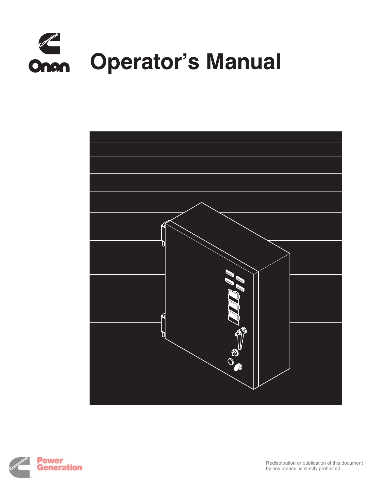
OT III
Redistribution or publication of this document
by any means, is strictly prohibited.
Transfer Switch
40 to 1000 Amperes
Nonautomatic/Remote
;HFGIED @%>%.%
-+)J'((, +J-*
Page 2

9< =E@ GA /GFK@FKJ
Redistribution or publication of this document
by any means, is strictly prohibited.
SECTION TITLE PAGE
1INTRODUCTION 1-1. . . . . . . . . . . . . . . . . . . . . . . . . . . . . . . . . . . . . . . . . . . . . . . . . . . . . . . . . . .
Operator’s Manual1-1. . . . . . . . . . . . . . . . . . . . . . . . . . . . . . . . . . . . . . . . . . . . . . . . . . . . . . . .
Transfer Switch Application 1-1. . . . . . . . . . . . . . . . . . . . . . . . . . . . . . . . . . . . . . . . . . . . . . . .
Model Identification 1-1. . . . . . . . . . . . . . . . . . . . . . . . . . . . . . . . . . . . . . . . . . . . . . . . . . . . . . .
How to Obtain Service1-2. . . . . . . . . . . . . . . . . . . . . . . . . . . . . . . . . . . . . . . . . . . . . . . . . . . .
2DESCRIPTION 2-1. . . . . . . . . . . . . . . . . . . . . . . . . . . . . . . . . . . . . . . . . . . . . . . . . . . . . . . . . . . .
Cabinet2-1. . . . . . . . . . . . . . . . . . . . . . . . . . . . . . . . . . . . . . . . . . . . . . . . . . . . . . . . . . . . . . . . .
Transfer Switch 2-2. . . . . . . . . . . . . . . . . . . . . . . . . . . . . . . . . . . . . . . . . . . . . . . . . . . . . . . . . .
3OPERATION 3-1. . . . . . . . . . . . . . . . . . . . . . . . . . . . . . . . . . . . . . . . . . . . . . . . . . . . . . . . . . . . . .
Local Operation 3-1. . . . . . . . . . . . . . . . . . . . . . . . . . . . . . . . . . . . . . . . . . . . . . . . . . . . . . . . .
Remote Operation 3-1. . . . . . . . . . . . . . . . . . . . . . . . . . . . . . . . . . . . . . . . . . . . . . . . . . . . . . . .
Manual Operation 3-2. . . . . . . . . . . . . . . . . . . . . . . . . . . . . . . . . . . . . . . . . . . . . . . . . . . . . . . .
Preventive Maintenance3-3. . . . . . . . . . . . . . . . . . . . . . . . . . . . . . . . . . . . . . . . . . . . . . . . . . .
4TROUBLESHOOTING 4-1. . . . . . . . . . . . . . . . . . . . . . . . . . . . . . . . . . . . . . . . . . . . . . . . . . . . . .
Transfer Switch Does Not Transfer to the Standby Source4-1. . . . . . . . . . . . . . . . . . . . .
Transfer Switch Does Not Retransfer to the Normal Source4-1. . . . . . . . . . . . . . . . . . . .
INCORRECT SERVICE OR REPLACEMENT OF PARTS CAN RESULT IN
DEATH, SEVERE PERSONAL INJURY, AND/OR EQUIPMENT DAMAGE.
SERVICE PERSONNEL MUST BE QUALIFIED TO PERFORM ELECTRICAL
AND/OR MECHANICAL SERVICE.
i
Page 3
8<A@KM 6I@><LKDGFJ
Redistribution or publication of this document
by any means, is strictly prohibited.
This manual includes the following symbols to indi-
cate potentially dangerous conditions. Read the
manual carefully and know when these conditions
exist. Then take the necessary steps to protect per-
sonnel and the equipment.
This symbol warns of immediate
hazards that will result in severe personal injury
or death.
;.74241
unsafe practice that can result in severe per-
sonal injury or death.
/.:9254
safe practice that can result in personal injury
or product or property damage.
High voltage in OT transfer switch components pre-
sents serious shock hazards that can result in se-
vere personal injury or death. Read and follow
these suggestions.
Keep the transfer switch cabinet closed and locked.
Make sure only authorized personnel have the cabi-
net and operational keys.
This symbol refers to a hazard or
This symbol refers to a hazard or un-
Due to the serious shock hazard from high voltages
within the cabinet, all service and adjustments to
the transfer switch must be performed only by an
electrician or authorized service representative.
If the cabinet must be opened for any reason:
1. Move the operation selector switch on the gen-
erator set to Stop.
2.Disconnect the starting batteries of the generator set (remove the ground [–] lead first).
3.Remove AC power to the transfer switch. If the
instructions require otherwise, use extreme
caution due to the danger of shock hazard.
Place rubber insulative mats on dry wood platforms
over metal or concrete floors when working on any
electrical equipment. Do not wear damp clothing
(particularly wet shoes) or allow skin surfaces to be
damp when handling any electrical equipment.
Jewelry is a good conductor of electricity and
should be removed when working on the electrical
equipment.
Do not work on this equipment when mentally or
physically fatigued, or after consuming alcohol or
any drug that makes the operation of equipment un-
safe.
OT3-N-2
ii
Page 4
&$ 2FKIG?L>KDGF
Redistribution or publication of this document
by any means, is strictly prohibited.
OPERATOR’S MANUAL
This operator’s manual provides information necessary for operation of an OT III transfer switch with
a nonautomatic/remote control.
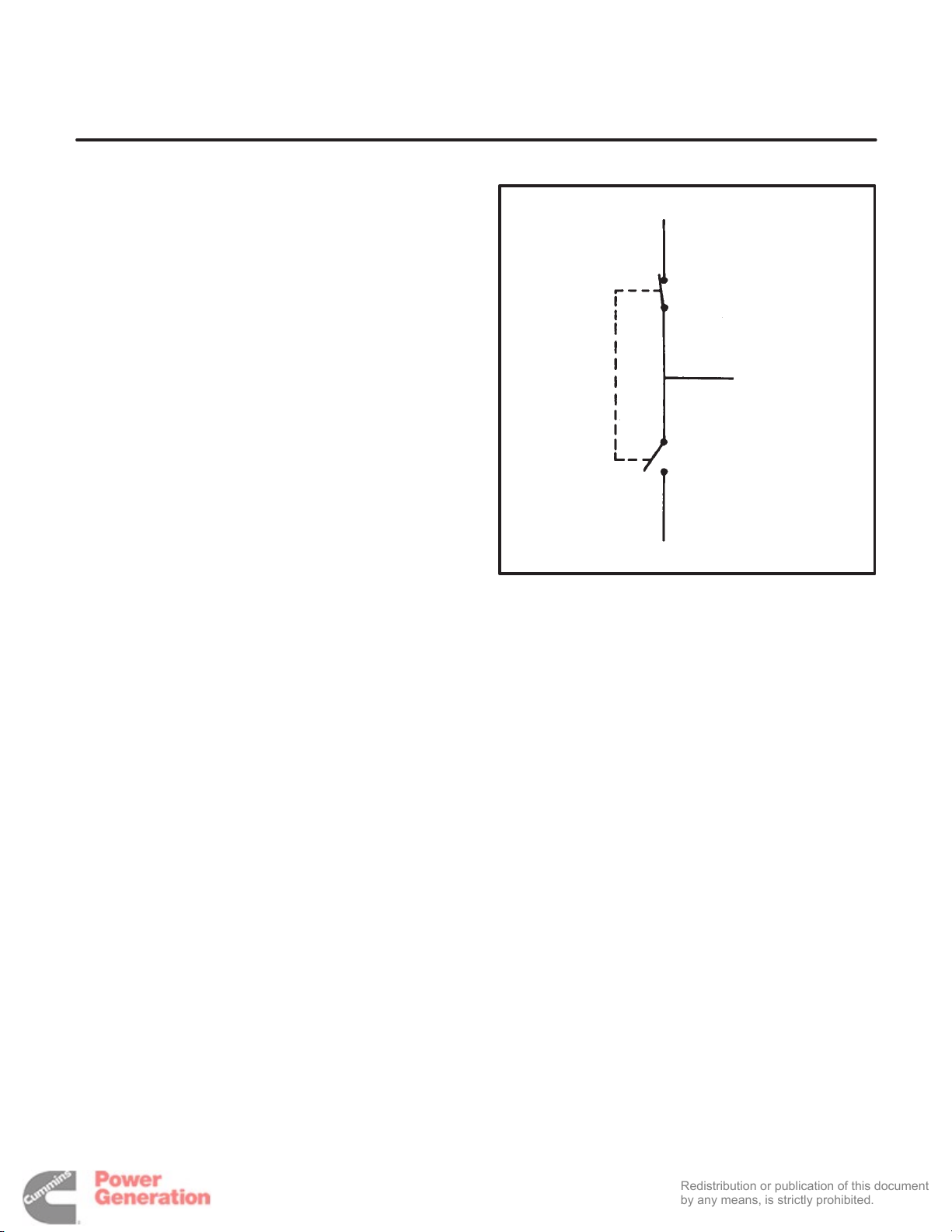
TRANSFER SWITCH APPLICATION
Transfer switches are an essential part of a build-
ing’s standby (or emergency) power system. The
Normal power source, commonly the utility line, is
backed up by a Standby power source, often an
electric generating set. A transfer switch supplies
the electrical load with power from one of these two
power sources.
The load is connected to the common of the transfer
switch (Figure 1-1). Under normal conditions, the
load is supplied with power from the Normal source
(as illustrated). If the Normal power source must be
interrupted, the load is transferred to the Standby
power source. When Normal power returns, the
load should be retransferred to the Normal power
source. The transfer and retransfer of the load are
the two most basic functions of a transfer switch.
9:=8.7
7:.1
>?.91/C
FIGURE 1-1. LOAD TRANSFER SWITCH
(TYPICAL FUNCTION)
SC1101
Operation of a nonautomatic/remote transfer
switch is initiated either by an operator at the trans-
fer switch or by an external signal from a remote
source.
MODEL IDENTIFICATION
Identify your model by referring to the Model and
Specification number as shown on the nameplate.
Electrical characteristics are shown on the lower
portion of the nameplate, which is located on the
cabinet door.
If it is necessary to contact a dealer or distributor re-
garding the transfer switch, always give the com-
plete Model, Specification, and Serial number. This
information is necessary to properly identify your
unit among the many types manufactured.
1-1
Page 5

HOW TO OBTAIN SERVICE
Redistribution or publication of this document
by any means, is strictly prohibited.
When the transfer switch requires servicing, con-
tact your nearest dealer or distributor. Factory-
trained Parts and Service representatives are
ready to handle all your service needs.
If unable to locate a dealer or distributor, consult the
Yellow Pages. Typically, our distributors are listed
under:
GENERATORS-ELECTRIC,
ENGINES-GASOLINE OR DIESEL, OR
RECREATIONAL VEHICLES-EQUIPMENT,
PARTS AND SERVICE.
For the name of your local Cummins /Onan or
Onan-only distributor in the United States or Canada, call 1-800-888-ONAN. (This automated serv-
ice utilizes touch-tone phones only.) By entering
your area code and the first three digits of your local
telephone number, you will receive the name and
telephone number of the distributor nearest you.
For the name of your local Cummins-only distributor, or if you need more assistance, please call
Onan Corporation, 1-612-574-5000, 7:30 AM to
4:00 PM, Central Standard Time, Monday through
Friday.
When contacting your distributor, always supply the
complete Model Number and Serial Number as
shown on the nameplate.
Cummins is a registered trademark of Cummins Engine Company.
Onan is a registered trademark of Onan Corporation.
1-2
Page 6

'$ 0@J>IDHKDGF
Redistribution or publication of this document
by any means, is strictly prohibited.
CABINET
The standard cabinet (Figure 2-1) meets the re-
quirements for a UL Type 1 cabinet. This type is
designated as a general-purpose, indoor cabinet.
Indicator Lamps
There are four indicator lamps on the cabinet door.
The Normal Available and Standby Available lamps
are lit whenever their corresponding power sources
are producing power. These two lamps can be lit simultaneously.
The Normal Connected lamp is lit when the Normal
source is connected to the load.
The Standby Connected lamp is lit when the
Standby source is connected to the load.
9:=8.7
0:9920?21 7.8;
Normal/Standby Switch
This three-position (spring return to center) switch
is used to electrically select which source is con-
nected to the load. The Normal position causes the
Normal source to be connected. The Standby posi-
tion causes the Standby source to be connected.
Under electrical control, the transfer switch will con-
nect to a source only if voltage is present at that
source.
The Normal/Standby switch controls transfer
switch position only when the Local/Remote switch
is in the Local position.
>?.91/C
0:9920?21 7.8;
9:=8.7
.A.67./72 7.8;
;5.>2 >2720?:=
>B6?05 #3:=
:;?6:9.7 82?2=>$
7:0.7&=28:?2
>B6?05
>?.91/C
.A.67./72 7.8;
:;?6:9.7 .0
A:7?82?2=
:;?6:9.7 .0
.882?2=
:;?6:9.7 3=2<@290C
82?2=
9:=8.7&>?.91/C
>B6?05
3&+-)#-J
FIGURE 2-1. OT III CABINET WITH OPTIONS
2-1
Page 7

Local/Remote Switch
Redistribution or publication of this document
by any means, is strictly prohibited.
The Local/Remote switch is used to enable the Normal/Standby switch (Local position) or the remote
control inputs at TB2 (Remote position).
make and break the current flow. When closed to
either the Normal or the Standby power source, the
contacts are mechanically held. A mechanical in-
terlock prevents them from closing to both power
sources at the same time.
Optional Meter Package
The optional meter package includes an AC amme-
ter, an AC voltmeter, a frequency meter, and a
phase selector switch.
AC Voltmeter: The voltmeter measures line-to-line
voltage of the selected power source.
AC Ammeter: The ammeter measures the line cur-
rents of the load.
Frequency Meter: This meter measures the out-
put frequency of the selected power source in hertz.
Phase Selector Switch: This switch is used to se-
lect the source and phase to be measured.
TRANSFER SWITCH
The transfer switch (Figure 2-2) opens and closes
the contacts that transfer the load between Normal
and Standby power. The transfer switch is mechani-
cally interlocked to prevent simultaneous closing to
both power sources. The main parts of the transfer
switch discussed here are the contact assemblies,
linear actuator, Motor Disconnect switch, and auxil-
iary contacts.
Contact Assemblies
Linear Actuator
The linear actuator is a linear induction motor that
moves the contact assemblies between the Normal
power source and the Standby power source. Nor-
mally, linear actuator operation is initiated electrically. Manual operation of the transfer switch is also
possible. Refer to Manual Operation in the Opera-
tion section.
Motor Disconnect Switch
The Motor Disconnect toggle switch, on the acces-
sory control panel, enables and disables the linear
actuator. Place the switch in the Off position for
manual operation and in the Auto position for elec-
trical (local/remote) operation.
Auxiliary Contacts
Auxiliary contacts are provided on the Normal and
Emergency (Standby) sides of the transfer switch.
They are actuated by operation of the transfer
switch during transfer and retransfer.
The Normal side auxiliary contact switch is actuated
when the transfer switch is in the Normal position.
The Emergency side auxiliary contact switch is ac-
tuated when the transfer switch is in the Emergency
position.
The automatic transfer switch has either three or
four poles. Three pole transfer switches are pro-
vided with a neutral bar. The contact assemblies
The auxiliary contacts have current ratings of 10
amperes at 250 VAC. The contacts are wired to ter-
minal block TB1.
2-2
Page 8

69160.?:=
Redistribution or publication of this document
by any means, is strictly prohibited.
7.8;>
:;?6:9.7
82?2=>
>B6?052>
:;?6:9.7
;=:4=.8821
?=.9>6?6:9
.002>>:=C
0:9?=:7
;.927
8:?:=
16>0:9920?
>B6?05
FIGURE 2-2. INTERIOR/COMPONENTS
?=.9>32=
>B6?05
.>>28/7C
8/&*,&#&J
2-3
Page 9

Programmed Transition Option
Redistribution or publication of this document
by any means, is strictly prohibited.
The optional Program Transition module (Figures
2-2 and 2-3) is used to introduce a pause during
transition. Programmed transition is the capability
of the transfer switch to assume a mid-transition po-
sition, for an adjustable interval of time, when the
load is neither connected to the Normal power
source nor to the Standby power source.
This feature allows residual voltage from motor
loads to decay to an acceptable level before trans-
fer is completed. The length of time that the transfer
switch is in the midposition can be adjusted from 0
to 7.5 seconds or 0 to 60 seconds, depending on the
timer option. The proper adjustment is a function of
the motor and its connected load.
To set the time delay, align the slot on the potenti-
ometer with the desired marking on the faceplate
(Figure 2-3).
If a time delay is desired, make sure that the Delay/
No Delay switch is in the Delay position.
SC1583
FIGURE 2-3. PROGRAM TRANSITION MODULE
Load Shed
The Load Shed function is used to disconnect the
load from an available Standby source in order to
reduce the power consumed from that source.
When the load shed function is initiated, the switch
is moved to the neutral position.
The load shed function is initiated by a customer-
supplied signal.
Auxiliary Relays Option
Optional auxiliary relays provide contacts for ener-
gizing external alarms, remote indicators, and control equipment such as louver motors and water
pumps.
Alarm Module Option
The optional alarm module (Figure 2-4) provides an
audible indication that the transfer switch has trans-
ferred to the Standby power source.
A push button on the alarm module provides a
means to silence the horn.
The Alarm lamp indicates that the transfer switch is
in the Standby Connected position. If the horn is si-
lenced, the Horn Silenced lamp will also light. Both
lamps will stay lit until the transfer switch is moved
from the Standby Connected position to the discon-
nected (neutral) or Normal Connected position.
(%%#(--,
FIGURE 2-4. ALARM MODULE
2-4
Page 10

($ 5H@I<KDGF
Redistribution or publication of this document
by any means, is strictly prohibited.
LOCAL OPERATION
;.74241
rapid movement of the manual operator han-
dles and presents a hazard of serious personal
injury. Keep the cabinet door closed.
To set the transfer switch for local operation:
1. Place the Local/Remote switch in the Local po-
sition.
2.Place the Motor Disconnect switch (on the Ac-
cessory Control Panel) in the Auto position.
To transfer the load to the Standby source:
1. Check that the Standby Available lamp is lit.
(The transfer switch will only permit transfer to
the Standby source if the Standby source volt-
age is available.)
2.Move the Normal/Standby switch to the
Standby position and hold it there until the
Standby Connected lamp is lit.
To transfer the load to the Normal source:
1. Check that the Normal Available lamp is lit.
(The transfer switch will only permit transfer to
the Normal source if the Normal source voltage
is available.)
2.Move the Normal/Standby switch to the Normal position and hold it there until the Normal
Connected lamp is lit.
Transfer switch operation results in
REMOTE OPERATION
;.74241
rapid movement of the manual operator han-
dles and presents a hazard of serious personal
injury. Keep the cabinet door closed.
To set the transfer switch for remote operation:
1. Place the Local/Remote switch in the Remote
position.
2.Place the Motor Disconnect switch (on the Ac-
cessory Control Panel) in the Auto position.
Remotely controlled transfer to the Standby source
is accomplished by closing a set of normally open
contacts that are connected across terminals 1 and
3 of TB2.
The contacts must be held closed until transfer is
complete.
Remotely controlled retransfer to the Normal
source is accomplished by closing a set of normally
open contacts that are connected across terminals
1 and 2 of TB2.
The contacts must be held closed until transfer is
complete.
As with local operation, the transfer switch permits
transfer and retransfer only when the selected
source voltage is present.
Transfer switch operation results in
3-1
Page 11

MANUAL OPERATION
Redistribution or publication of this document
by any means, is strictly prohibited.
The transfer switch has operator handles for manu-
ally transferring the load. Use the following proce-
dure:
;.74241
rear side of the cabinet door presents a shock
hazard that can cause severe personal injury or
death. Use extreme caution to avoid touching
electrical contacts whenever the cabinet door is
open.
If possible, remove all AC power to the transfer
switch before manually operating the switch. If
it is necessary to perform manual operation
with AC power connected, follow the “Safety
Related Work Practices” listed in NFPA 70E.
1. Place the Local/Remote switch in the Local po-
sition.
2.Open the cabinet door of the transfer switch.
3.Move the Motor Disconnect switch to the Off
position.
AC power within the cabinet and the
4. Transfer from the Normal to the Standby
power source:
A.Pull the upper manual operator handle
down.
B.Push the lower manual operator handle
down.
Retransfer from the Standby to the Normal
power source:
C.Pull the lower manual operator handle up.
D.Push the upper manual operator handle
up.
;.74241
Transfer switch operation re-
sults in rapid movement of the manual op-
erator handles and presents a hazard of se-
rious personal injury. Keep hands clear of
handles when switching back to Auto.
5. To return to electrical operation, move the Mo-
tor Disconnect switch to the Auto position.
6.Close the cabinet door.
7.If remote control operation is being used, place
the Local/Remote switch in the Remote position.
3-2
Page 12

PREVENTIVE MAINTENANCE
Redistribution or publication of this document
by any means, is strictly prohibited.
Performing the yearly preventive maintenance procedures in Ta ble 3-1 will result in operational reliability of the
transfer switch.
The following procedures must only be performed by technically qualified personnel, following the procedures
provided in the Service manual (962-0512). If repair or replacement of components is necessary, call
your dealer or distributor.
;.74241
that can cause severe personal injury or death. In addition, incorrect installation, service, or parts re-
placement can result in severe personal injury, death, and/or equipment damage. Therefore, all cor-
rective service procedures must only be performed by technically qualified personnel, following the
procedures provided in the Service manual (962-0512).
;.74241
death unless all AC power is removed. Be sure to move the generator set operation selector switch to
Stop, disconnect AC line power, disconnect the battery charger from its AC power source, and disconnect the starting battery (negative [–] lead first) before servicing.
;.74241
cause any spark, arc, or flame while servicing batteries.
1. DISCONNECT ALL SOURCES OF AC POWER:
Disconnect both AC power sources from the transfer switch before continuing. Turn the generator set
operation selector switch to Stop. (The selector switch is located on the generator set control panel.)
If there is an external battery charger, disconnect it from its AC power source. Then disconnect
the set starting battery (negative [–] lead first).
2.CLEAN
3.INSPECT
4. PERFORM ROUTINE MAINTENANCE
5. CONNECT AC POWER AND CHECK OPERATION
AC power within the cabinet and the rear side of the cabinet door presents a shock hazard
The transfer switch presents a shock hazard that can cause severe personal injury or
Ignition of explosive battery gases can cause severe personal injury. Do not smoke or
TABLE 3-1. ANNUAL PREVENTIVE MAINTENANCE
a.Thoroughly dust and vacuum all controls, meters, switching mechanism components, interior
buswork, and connecting lugs.
b.Close the cabinet door and wash exterior surfaces with a damp sponge (mild detergent and
water). Do not allow water to enter the cabinet, especially at meters, lamps, and switches.
a.Check buswork and supporting hardware for carbon tracking, cracks, corrosion, or any other
types of deterioration. If replacement is necessary, call your dealer or distributor.
b.Check stationary and movable contacts. If contact replacement is necessary, the procedures are
described in section 4 of the Service manual (962-0512).
c.Check system hardware for loose connections. Tighten as indicated in step 4.
d. Check all control wiring and power cables (especially wiring between or near hinged door) for
signs of wear or deterioration.
e. Check all control wiring and power cables for loose connections. Tighten as indicated in step 4.
f. Check the cabinet interior for loose hardware. Tighten as indicated in step 4.
a.Tighten buswork, control wiring, power cables, and system hardware, as necessary. Hardware
torque values are given in section 4 of the Service manual (962-0512). Retorque all cable lug
connections. Lug torque requirements are listed in section 1 of the Service manual.
b.Service or replace the batteries.
a.Connect the set starting battery (negative [–] lead last). Connect the normal AC power source,
enable the backup power source. If applicable, connect power to the battery charger.
b.Verify proper operation of the battery charger.
c.Test system operation as described in this section. Close and lock the cabinet door.
3-3
Page 13

Redistribution or publication of this document
by any means, is strictly prohibited.
3-4
Page 14

)$ 9IGL=E@JCGGKDFB
Redistribution or publication of this document
by any means, is strictly prohibited.
The following procedures describe preliminary
troubleshooting checks. If the trouble persists, call
your dealer or distributor.
;.74241
rear side of the cabinet door presents a shock
hazard that can cause severe personal injury or
death. Use extreme caution to avoid touching
electrical contacts whenever the cabinet door is
open.
AC power within the cabinet and the
TRANSFER SWITCH DOES NOT
TRANSFER TO THE STANDBY SOURCE
1. Check the Motor Disconnect switch. It should
be in the Auto position.
2.Are the Local/Remote and Normal/Standby
switches in the correct positions?
3.Has the programmed transition time delay (if
equipped) expired?
4. Is the Standby source voltage present? Check
the Standby Available lamp. Check the
Standby source voltage.
5. Manually transfer the switch (see Operation).
Call your dealer or distributor.
TRANSFER SWITCH DOES NOT
RETRANSFER TO THE NORMAL SOURCE
1. Check the Motor Disconnect switch. It should
be in the Auto position.
2.Are the Local/Remote and Normal/Standby
switches in the correct positions?
3.Has the programmed transition time delay (if
equipped) expired?
4. Is the Normal source voltage present? Check
the Normal Available lamp. Check the Normal
source voltage.
5. Manually retransfer the switch (see Opera-
tion). Call your dealer or distributor.
4-1
Page 15

Redistribution or publication of this document
by any means, is strictly prohibited.
4-2
Page 16

Cummins Power Generation
Redistribution or publication of this document
by any means, is strictly prohibited.
1400 73rd Avenue N.E.
Minneapolis, MN 55432
1-800-888-6626
763-574-5000 International Use
Fax: 763-528-7229
Cummins is a registered trademark of Cummins Inc.
 Loading...