

Page 1
1-2019
01-2019
Operator Manual
Onan P4500i Inverter
Digital Inverter Generator
Onan P4500i
3700 Running Watts
4500 Peak Watts
REMOTE
START
STOP
120V AC 30A TT-30R
GROUND
RUN
Push-button electric start
30A
START
EASY START
ECO MODE
120V AC 20A 5-20R
Have Questions?
1-800-CUMMINS
PARALLEL
OPERATION OUTLETS
REQUIRES SPECIAL CABLES
CONSULT OWNERS MANUAL
!
FUEL
START
INDICATOR
20A
LOW
OIL
OVERLOAD
OUTPUT
READY
DC 5V
1.0A 2.1A
DATA CENTER
RESET
F: Remaining Run Time
kW
P: Power Output in
L: Fuel Level in Liters
V: Voltage
Lifetime Run Hours
English
Original Instructions
1-2019
A062R852 (Issue 1)
Page 2

Page 3

1-2019
WARNING
Operating, servicing and maintaining this equipment can expose you to chemicals including engine exhaust,
carbon monoxide, phthalates, and lead, which are known to the State of California to cause cancer and birth
defects or other reproductive harm. To minimize exposure, avoid breathing exhaust, do not idle the engine
except as necessary, service your equipment in a well-ventilated area and wear gloves or wash your hands
frequently when servicing your equipment. For more information go to www.P65Warnings.ca.gov.
DISCLAIMERS:
All information, illustrations and specications in this manual are based on the latest information available at the time of publishing.
The illustrations used in this manual are intended as representative reference views only. Moreover, because of our continuous product
improvement policy, we may modify information, illustrations and/or specications to explain and/or exemplify a product, service or
maintenance improvement. We reserve the right to make any change at any time without notice. Some images may vary depending
upon which model is shown.
ALL RIGHTS RESERVED:
No part of this publication may be reproduced or used in any form by any means – graphic, electronic or mechanical, including photocopying,
recording, taping or information storage and retrieval systems – without the written permission of Cummins Inc.
DANGER
This manual contains important instructions for operating this inverter. For your safety and the safety of others, be sure to read this
manual thoroughly before operating the inverter. Failure to properly follow all instructions and precautions can cause you and others to be
seriously hurt or killed.
TABLE OF CONTENTS
TECHNICAL SPECIFICATIONS ..................3
PRODUCT REGISTRATION .....................3
For Your Records: .........................3
Product Registration .......................3
Product Registration Form ...................3
SAFETY .....................................4
Safety Denitions ..........................4
Safety Symbol Denitions ....................4
General Safety Rules ........................5
UNPACKING .................................6
ASSEMBLY ..................................7
Hooking Up the Battery ......................7
FEATURES ..................................8
Basic Inverter Features .....................8
Control Panel Features ......................9
OPERATION .................................10
Before Starting the Inverter ...................10
Location Selection .......................10
Weather ...............................10
Grounding the Inverter ....................10
High Altitude Operation ...................10
Power Cord ...............................11
Transporting the Inverter .....................12
Initial Oil Fill ...............................13
Adding/Checking Engine Fluids and Fuel ........13
Checking and/or Adding Engine Oil ............13
Adding Gasoline to the Fuel Tank ..............14
Starting the Inverter .........................14
Electric Start ...........................15
Manual Start ............................15
Wireless Remote Start ....................15
How to manually set the choke ................16
Stopping the Inverter ........................17
Using Eciency Mode ......................17
Resetting the Reset Breaker ..................17
Programming Remote Start Fob ...............17
MAINTENANCE ..............................18
Maintenance Schedule ......................18
Engine Oil Maintenance .....................19
Checking Engine Oil ........................19
Adding Engine Oil ..........................19
Changing Engine Oil ........................19
Air Filter Maintenance .......................20
Cleaning the Air Filter .....................20
Draining the Float Bowl ......................21
Spark Plug Maintenance .....................21
Cleaning the Spark Arrestor ..................22
Checking and Adjusting Valve Lash ............22
Cleaning the Inverter ........................23
Battery Service ............................23
Storage ..................................24
TROUBLESHOOTING .........................25
EXPLODED AND ENGINE VIEWS ................26
P4500i Schematic ..........................26
P4500i Exploded View ......................27
P4500i Engine View .........................29
Copyright © 2019 Cummins Inc.
2
A062R852 (Issue 1)
Page 4
1-2019
TECHNICAL SPECIFICATIONS
Model
P4500i 3700 4500 3.4/13 3600 TCI F7RTC 224 70X58 0.60 10W30 <3%
Running
Watts
Peak
Watts
Fuel Tank
Size (G/L)
Rated
Speed
(RPM)
Ignition
Type Spark plug
Engine
Disp
(cc)
Stroke
X Bore
Oil Cap.
(L) Oil Type THD
FOR YOUR RECORDS:
Date of Purchase:
Inverter Model Number:
Purchased from Store/Dealer:
Inverter Serial Number:
IMPORTANT: KEEP YOUR PURCHASE RECEIPT TO ENSURE TROUBLE-FREE WARRANTY
COVERAGE.
PRODUCT REGISTRATION
To ensure trouble-free warranty coverage, it is important you
register your Cummins inverter.
You can register your inverter by either:
1. Filling in the product registration form below and mailing to:
Product Registration
Cummins Inc
301 E. Market St.
Indianapolis, IN 46204
2. Registering your product Online at www.cummins.com/support/product-registration
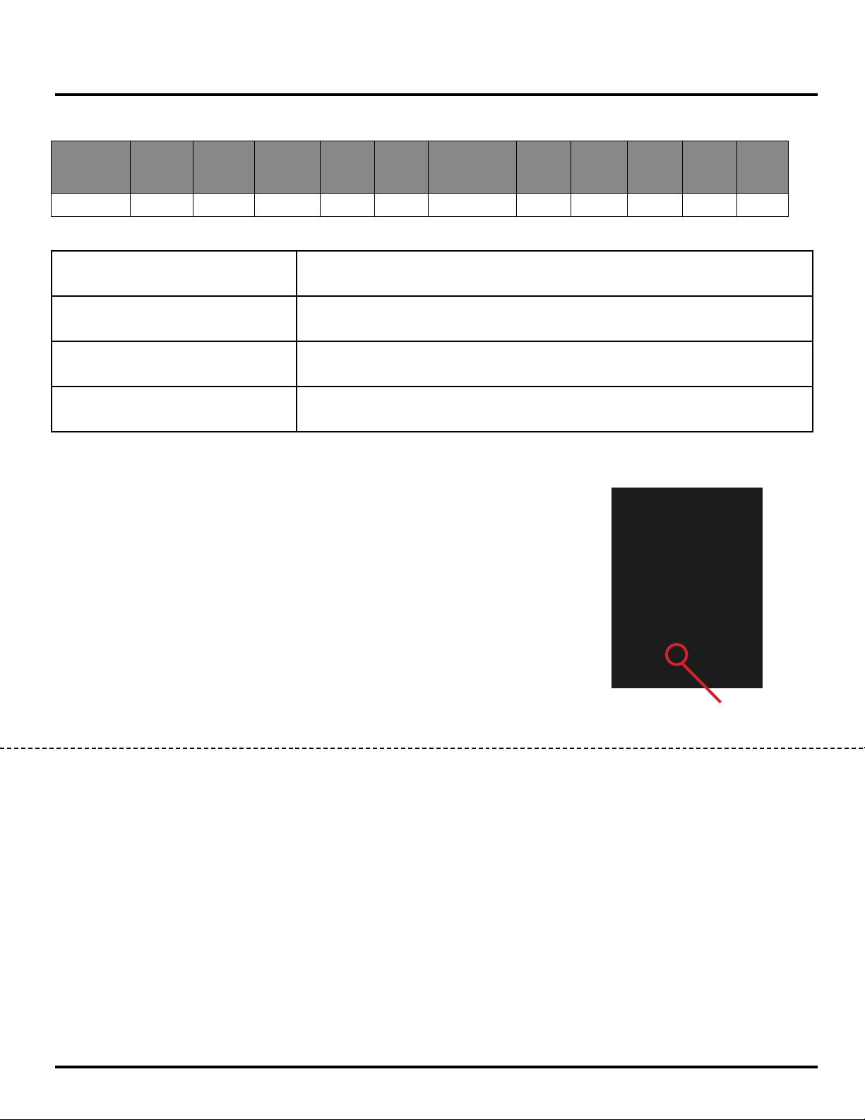
To register your inverter you will need to locate the following information:
• Model Info Decal located on side panel.
• Serial Number on back.
SERIAL NUMBER
LOCATION
PRODUCT REGISTRATION FORM
PERSONAL INFORMATION INVERTER INFORMATION
First Name: _______________________________________ Model Number: _____________________________________
Last Name: _______________________________________ Serial Number: ______________________________________
Street Address: ___________________________________ Date Purchased: ____________________________________
Street Address: ___________________________________ Purchased From: ____________________________________
City, State, ZIP: ____________________________________ Phone Number: _____________________________________
Country: __________________________________________ E-Mail: _____________________________________________
Copyright © 2019 Cummins Inc.
3
A062R852 (Issue 1)
Page 5
SAFETY
1-2019
SAFETY DEFINITIONS
The words DANGER, WARNING, CAUTION and
NOTICE are used throughout this manual to highlight
important information. Be certain that the meanings of
these alerts are known to all who work on or near the
equipment.
This safety alert symbol appears
with most safety statements. It
means attention, become alert, your
safety is involved! Please read and
abide by the message that follows
the safety alerts symbol.
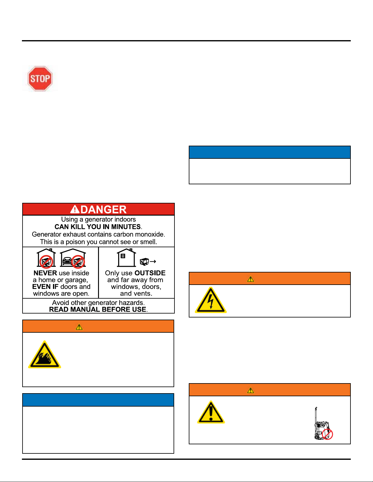
DANGER
Indicates a hazardous situation which, if not
avoided, will result in death or serious injury.
WARNING
Indicates a hazardous situation which, if not
avoided, could result in death or serious injury.
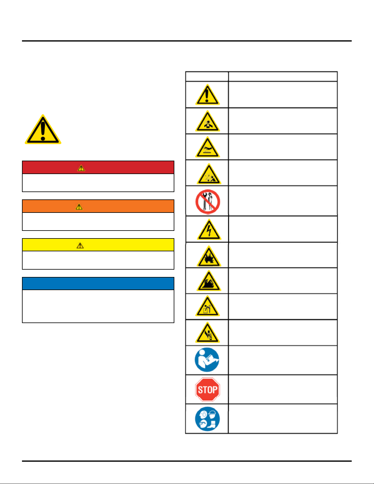
SAFETY SYMBOL DEFINITIONS
Symbol Description
Safety Alert Symbol
Asphyxiation Hazard
Burn Hazard
Burst/Pressure Hazard
Don’t leave tools in the area
Electrical Shock Hazard
CAUTION
Indicates a hazardous situation which, if not
avoided, could result in minor or moderate injury.
NOTICE
Indicates a situation which can cause damage to
the inverter, personal property and/or the environment, or cause the equipment to operate improperly.
NOTE: Indicates a procedure, practice or condition
that should be followed in order for the
inverter to function in the manner
intended.
Explosion Hazard
Fire Hazard
Lifting Hazard
Pinch-Point Hazard
Read Manufacturer’s Instructions
Read Safety Messages
Before Proceeding
Wear Personal Protective
Equipment (PPE)
Copyright © 2019 Cummins Inc.
4
A062R852 (Issue 1)
Page 6
1-2019
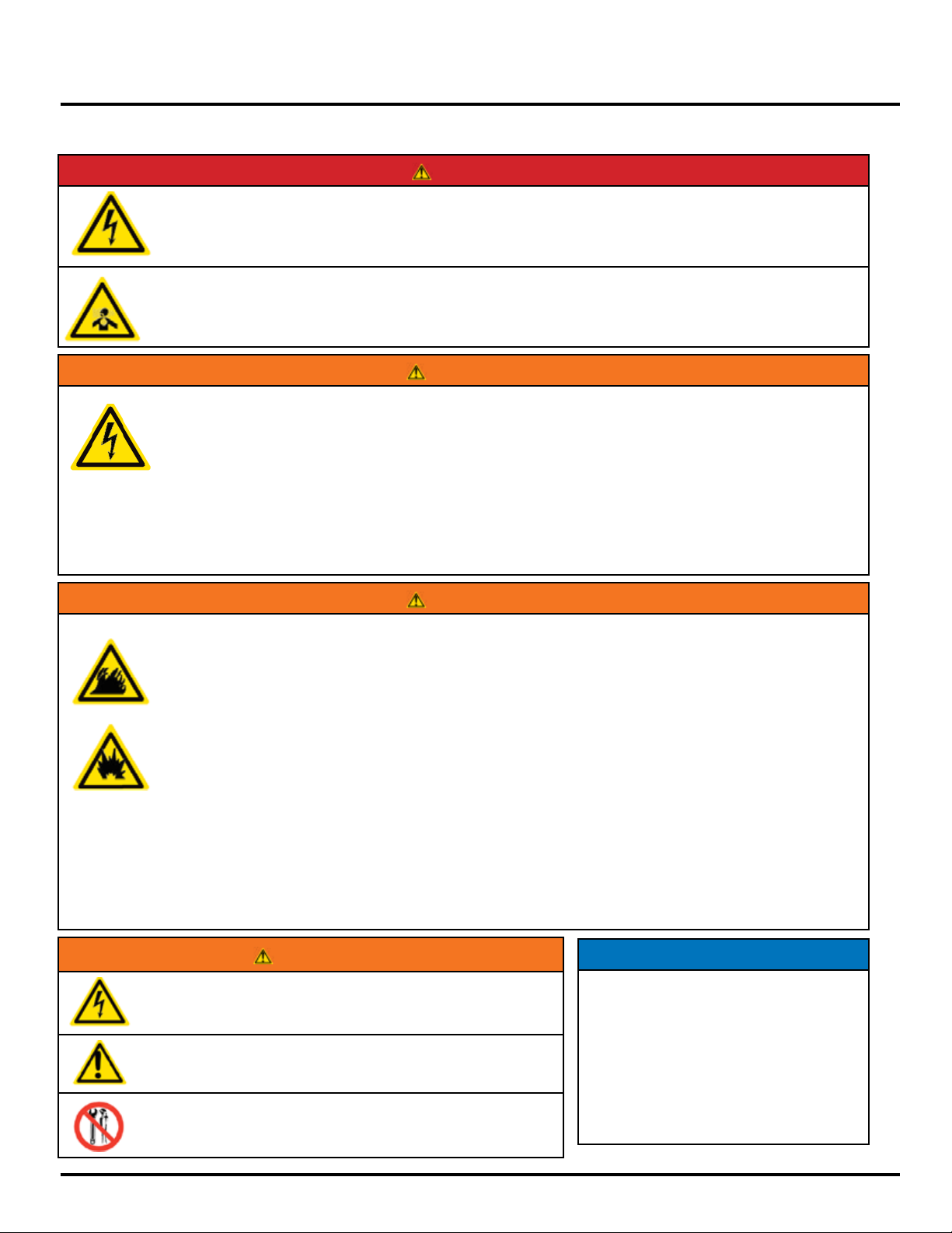
GENERAL SAFETY RULES
Never use the inverter in a location that is wet or damp. Never expose the inverter to rain, snow,
water spray or standing water while in use. Protect the inverter from all hazardous weather conditions.
Moisture or ice can cause a short circuit or other malfunction in the electrical circuit.
Never operate the inverter in an enclosed area. Engine exhaust contains carbon monoxide. Only
operate the inverter outside and away from windows, doors and vents.
Voltage produced by the inverter could result in death or serious injury.
• Never operate the inverter in rain or a ood plain unless proper precautions are taken to avoid being
subject to rain or a ood.
• Never use worn or damaged extension cords.
• Always have a licensed electrician connect the inverter to the utility circuit.
• Never touch an operating inverter if the inverter is wet or if you have wet hands.
• Never operate the inverter in highly conductive areas such as around metal decking or steel works.
• Always use grounded extension cords. Always use three-wire or double-insulated power tools.
• Never touch live terminals or bare wires while the inverter is operating.
• Be sure the inverter is properly grounded before operating.
SAFETY
DANGER
WARNING
WARNING
Gasoline and gasoline vapors are extremely ammable and explosive under certain conditions.
• Always refuel the inverter outdoors, in a well-ventilated area.
• Never remove the fuel cap with the engine running.
• Never refuel the inverter while the engine is running. Always turn engine o and allow the inverter to
cool before refueling.
• Only ll fuel tank with gasoline.
• Keep sparks, open ames or other form of ignition (such as match, cigarette, static electric source)
away when refueling.
• Never overll the fuel tank. Leave room for fuel to expand. Overlling the fuel tank can result in a
sudden overow of gasoline and result in spilled gasoline coming in contact with HOT surfaces.
Spilled fuel can ignite. If fuel is spilled on the inverter, wipe up any spills immediately. Dispose of rag
properly. Allow area of spilled fuel to dry before operating the inverter.
• Wear eye protection while refueling.
• Never use gasoline as a cleaning agent.
• Store any containers containing gasoline in a well-ventilated area, away from any combustibles or
source of ignition.
• Check for fuel leaks after refueling. Never operate the engine if a fuel leak is discovered.
WARNING
Never operate the inverter if powered items overheat,
electrical output drops, there is sparking, ames or smoke
coming from the inverter, or if the receptacles are damaged.
Never use the inverter to power medical support equipment.
Never modify the inverter.
Never operate the inverter if it vibrates
at high levels, if engine speed changes
greatly or if the engine misres often.
NOTICE
Always remove any tools or other service equipment used
during maintenance from the inverter before operating.
Copyright © 2019 Cummins Inc.
Always disconnect tools or appliances
from the inverter before starting.
5
A062R852 (Issue 1)
Page 7
SAFETY
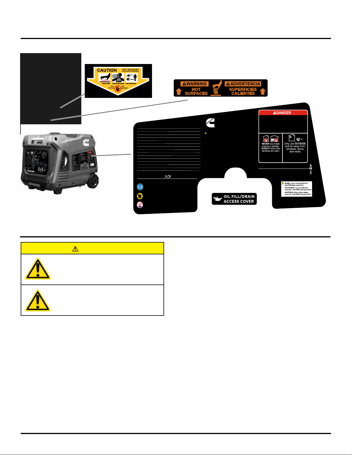
SAFETY LABELS AND DECALS
Model Modelo Onan P4500i
Part No Numero de parte A058U955
AC Voltage Voltaje 120V
Power (Running) Potencia (nominal) 3700W
Power (Peak) Potencia (pico) 4500W
Current Corriente 30A
DC Voltage Voltaje 5V
Current Corriente 2A
Frequency Frecuencia 60Hz
Phase Fase Single Soltero
RPM TR 5200
Power Factor Factor de potencia 1.0
Insul Class Clase de aislamiento F
Max Amb Temp Temperatura máxima 40
Fuel Combustible Gasoline
Fuel Tank Size Tamaño del tanque de combustible 12.8L/3.4G
Oil: SAE10W-30
Oil Capacity Capacidad de aceite .6 QT/20.3 OZ/600 ML
Read and understand operating instructions before starting.
Lea y comprenda las instrucciones de operación antes de
comenzar.
Provide proper ventilation! Do not operate in a confined area.
Proporcione una ventilación adecuada! No opere en un área
confinada.
Do not operate in wet conditions. Electrical shock may result and
could be fatal! No opere en condiciones húmedas. ¡Puede
producirse una descarga eléctrica y podría ser fatal!
o
C (104
Cummins Inc.
Columbus Indiana 47201 USA
Designed in Columbus, Ohio USA Made in China
Diseñado en Columbus, Ohio, EE. UU. Hecho en China
WARNING:
• Use gasoline with a minimum octane rating of 87.
• Do not direct exhaust fumes toward people, buildings or equipment.
• Check and refill oil as required to ensure proper inverter performance.
• When refueling, always stop the engine.
• Immediately wipe up any spilled fuel.
• Keep any flammable items away from this equipment.
• Do not touch or contact outlets with wet hands.
• Do not expose inverter directly to rain or snow.
• Do not connect the AC output to any indoor wiring.
• Clean spark arrestor every 50 hours to prevent engine damage.
• When operating your inverter, do not erect any barriers or obstacles
around the equipment or inhibit air or exhaust flow.
o
F)
Using a generator indoors
CAN KILL YOU IN MINUTES.
Generator exhaust contains carbon monoxide.
This is a poison you cannot see or smell.
Usar un generador en el interior PUEDE MATARLE EN
MINUTOS. El escape del generador contiene monóxido de
carbono. Este es un veneno que no puedes ver ni oler.
NUNCA lo use dentro de una
casa o un garaje, INCLUSO
SI las puertas y ventanas
están abiertas
Spark Plug Bujía
Use OEM spark plug only. Please refer to Owner’s Manual.
Utilice únicamente bujías OEM. Por favor, consulte el manual del propietario
Spark plug: Torch F7RTC Spark plug gap: .8 mm/.03 in
Use solo FUERA y lejos
de ventanas, puertas
y ventilaciones.
FOR USE IN DRY WEATHER PROTECTED LOCATIONS ONLY.
PARA USO EN LUGARES PROTEGIDOS CON TIEMPO SECO
SOLAMENTE.
1-2019
.
UNPACKING
CAUTION
Always have assistance when lifting
the inverter. The inverter is heavy;
lifting it could cause bodily harm.
Avoid cutting on or near staples
to prevent personal injury.
Tools required – box cutter or similar device.
1. Carefully cut the packing tape on top of the carton.
2. Fold back top aps to reveal the upper packing tray.
3. Remove and save the instruction manual, oil bottle,
oil funnel, LPG hose, spark plug socket wrench &
battery charger.
4. Remove and discard the upper packing tray.
5. Unfold the top of the plastic bag enclosing the
inverter.
6. Carefully cut the vertical corners of the carton to
access the inverter.
7. Recycle or dispose of the packaging materials
properly.
WHAT COMES IN THE BOX
Inverter
Battery
Manual
Quick Start Guide/Maintenance Schedule
Wireless Remote Starter (1)
.6 Liter Bottle of SAE 10W30 Oil (1)
11W Battery Charger, (14V .8A output) (1)
Spark Plug Socket Wrench (1)
Oil Funnel (1)
Copyright © 2019 Cummins Inc.
6
A062R852 (Issue 1)
Page 8
1-2019
Negative
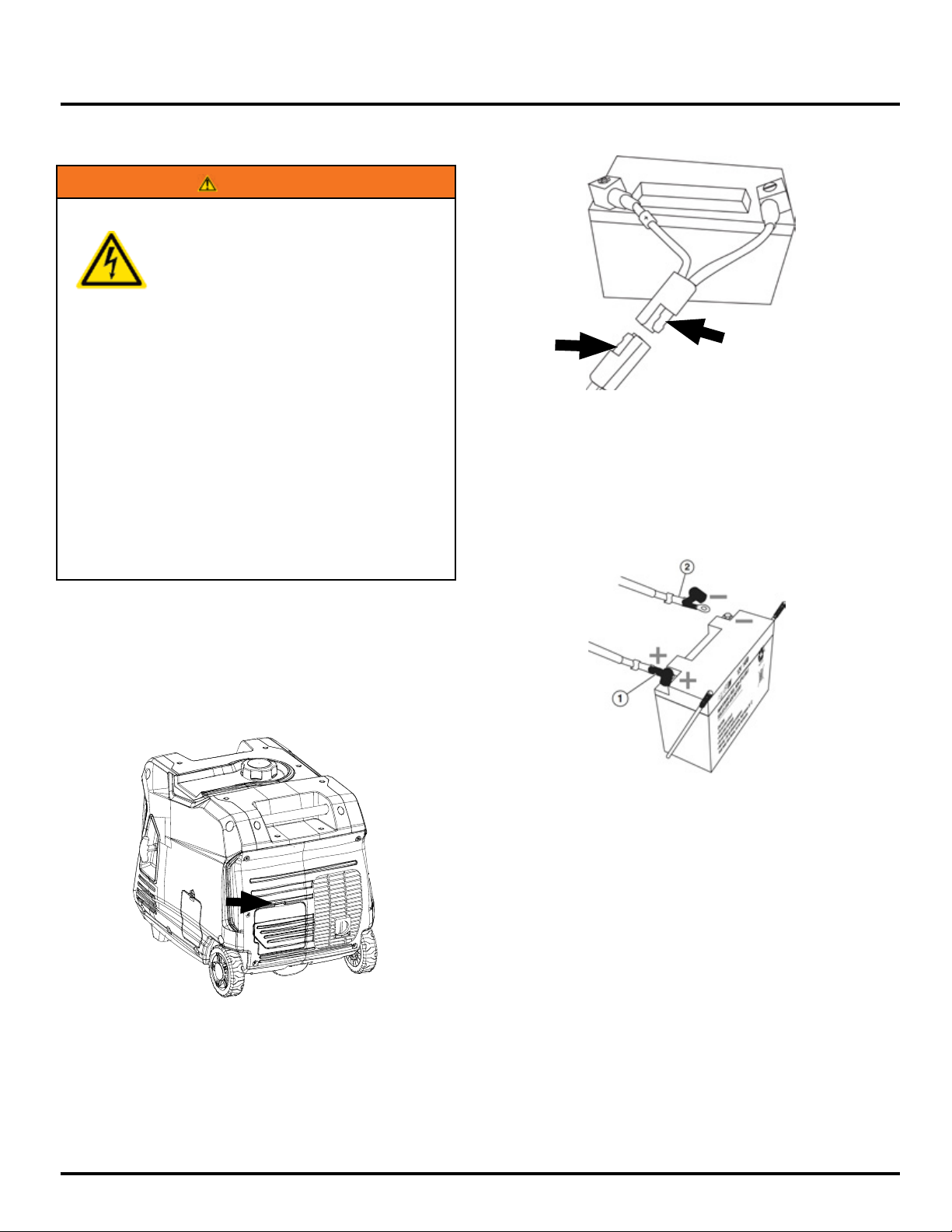
HOOKING UP THE BATTERY
WARNING
To avoid electrics shock:
• ALWAYS connect the positive (+)
battery cable (red boot) rst when
connecting battery cables.
• ALWAYS disconnect the negative (-)
battery cable (black boot) rst when
disconnecting battery cables.
• NEVER connect the negative (-)
battery cable (black boot) to the
positive (+) post on the battery.
• NEVER connect the positive (+)
battery cable (red boot) to the
negative (-) post on the battery.
• NEVER touch both battery posts
simultaneously.
• NEVER place a metal tool across
both battery posts.
• ALWAYS use insulated or
nonconducting tools when installing
the battery.
ASSEMBLY
4. Clip the battery quick connect from the battery
leads to the main lead inside the inverter (see image
above).
5. Verify the positive (+) battery cable (red boot) is
securely tightened to the positive (+) battery post.
Make sure boot is over battery post.
(Black)
NOTE: THE INVERTER COMES EQUIPPED WITH THE
POSITIVE BATTERY CABLE (RED BOOT) ALREADY
ATTACHED.
1. Unclip the battery access panel on the back of the
unit next to the muer (see Figure 1).
Figure 1: Battery service panel
2. Pull down on the battery strap clip and unhook it
from the mounting base.
3. Lift the battery up, withdraw it bottom-rst through
the battery access port and then stand it up vertically
in its normal orientation.
Positive
(Red)
Figure 2
6. Insert the battery top-rst through the battery access
port and stand it up on its mounting base.
7. Check that the battery is positioned correctly and
that the battery cables are not kinked or pinched.
8. Pass the battery strap under the negative (-) battery
cable and centrally over the top of the battery. Then
pull down on the battery strap clip and hook it onto
the mounting base.
9. Replace the battery access cover.
NOTE: The electric start inverter is equipped with a
battery charging feature. Once the engine is running,
a small charge is supplied to the battery via the
battery cables and will slowly recharge the battery.
Copyright © 2019 Cummins Inc.
7
A062R852 (Issue 1)
Page 9
FEATURES
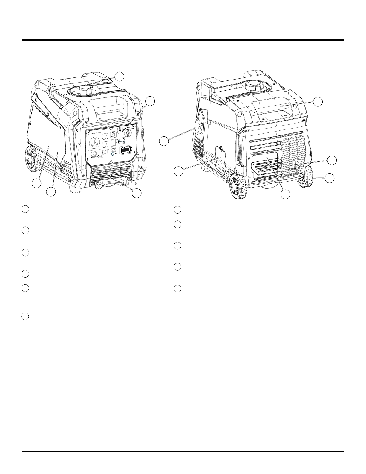
BASIC INVERTER FEATURES
4
1-2019
5
11
1
Control Panel: Contains the reset breaker,
outlets and warning lights.
2
Oil Access Cover: Remove the cover to
access the oil plug/dipstick.
3
Recoil Handle: Pull to manually start the
engine.
4
Fuel Cap: Close until clicking sound is heard.
1
9
3
6
2
7
8
7
Roller Board Wheels: For easy portability.
Telescoping Handle: Extends and retracts for
8
easy access.
Carry Handles: Built in handles to allow for
9
easy pick up.
10
Battery Access Panel: Easy access to
battery.
10
5
Engine Service Panel: Remove the panel to
access the engine, choke, air lter, spark plug
and oat bowl for maintenance.
6
Muer and Spark Arrestor: Avoid contact
until the engine is cooled down. The spark
arrestor prevents sparks from exiting the
muer. It must be removed for servicing.
Copyright © 2019 Cummins Inc.
11
Automatic Choke: Unit will automatically set
choke for cold starting.
8
A062R852 (Issue 1)
Page 10
1-2019
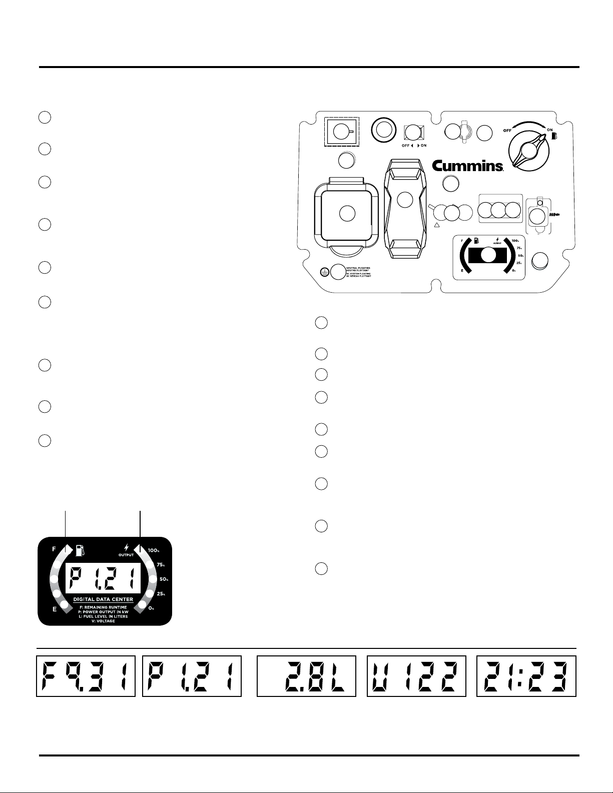
CONTROL PANEL FEATURES
FEATURES
120-Volt, 20-Amp Duplex Outlet (NEMA 5-20R): The
1
outlet is capable of carrying a maximum of 20 amps.
120-Volt 30 Amp TT-30 Outlet: Travel Trailer outlet
2
can supply a maximum of 30 amps and 120 volts.
20-Amp Circuit Breaker: Circuit breaker limits the
3
current that can be delivered through the 120-volt
duplex outlets to 20amps.
30-Amp Circuit Breaker: Circuit breaker limits the
4
current that can be delivered through the 120-volt
TT-30R to 30amps.
5
USB Duplex: 5V DC USB outlets that come with 1 and
2.1 amp rating.
Reset Breaker: If the inverter is overloaded, the reset
6
breaker will trip. The engine will continue to run, but
there will be no output from the inverter. Unplug the
devices and reduce the load. Push in the reset breaker
to reset it.
Eciency Mode Switch: When turned to the ON
7
position, the engine will sense the load needed and run
at a slower RPM to save fuel.
8
Ground Terminal: The ground terminal is used to
externally ground the inverter.
LED Data Center: Displays remaining run time (F),
9
power output in kW (P), fuel level in liters (L), voltage
(V) and lifetime hours.
Have Questions?
1-800-CUMMINS
20A
START
INDICATOR
15
OUTPUT
READY
1011
9
DATA CENTER
F: Remaining Run Time
P: Power Output in kW
L: Fuel Level in Liters
V: Voltage
Lifetime Run Hours
OVERLOAD
12
17
STOP
4
120V AC 30A TT-30R
RUN
EASY START
Push-button electric start
30A
START
16
120V AC 20A 5-20R
ECO MODE
7
13
3
PARALLEL
OPERATION OUTLETS
1
2
18
REQUIRES SPECIAL CABLES
!
CONSULT OWNERS MANUAL
8
GROUND
Output Ready LED: Indicates the inverter is ready to
10
be used.
Overload LED: Indicates that the inverter is overloaded.
11
12
Low Oil LED: Indicates low oil level.
Battery Charging Port: Used to charge battery when
13
unit is o.
Fuel Control Switch: Allows fuel to ow to the engine.
14
Start Indicator: Indicates that power is on, light will
15
remain lit the whole time the unit is on.
FUEL
14
LOW
OIL
5
DC 5V
1.0A 2.1A
6
RESET
% FUEL
REMAINING
% POWER
OUTPUT
AUTOMATIC ROTATING DATA NUMBER DISPLAY
Remaining Run Time:
Displays time remaining
with current fuel level and
power output. Does not
Power Output:
Displays electrical power
output to receptacles in
kilowatts.
display lifetime hours.
Copyright © 2019 Cummins Inc.
Push-Button Automated Start: Press and hold for 1-2
16
seconds to automatically start the engine. Press and
hold again for 1-2 seconds to stop the engine.
Engine Control Switch: Turns on battery and energizes
17
ignition system for electric and remote start. Shuts
engine o.
18
Parallel Ports: Used with Cummins 50A parallel kit
(sold separate). Combine with additional Cummins
P2500i inverter (sold separate) to achieve 50A output.
Ideal for RV applications.
Fuel level:
Displays current fuel
level in liters.
9
Voltage:
Displays current voltage
output of inverter.
A062R852 (Issue 1)
Lifetime Hours:
Displays the total run
time of the inverter.
Page 11
OPERATION
1-2019
BEFORE STARTING THE INVERTER
BEFORE STARTING THE INVERTER,
REVIEW SAFETY SECTION STARTING
ON PAGE 4.
Location Selection – Before starting the inverter, avoid
exhaust and location hazards by verifying:
• You have selected a location to operate the inverter
that is outdoors and well ventilated.
• You have selected a location with a level and solid
surface on which to place the inverter.
• You have selected a location that is at least 15 feet
(4.5 m) away from any building, other equipment or
combustible material.
• If the inverter is located close to a building, make
sure it is not located near any windows, doors and/
or vents.
Weather – Never operate your inverter outdoors during rain,
snow or any combination of weather conditions that could
lead to moisture collecting on, in or around the inverter.
Dry Surface – Always operate the inverter on a dry surface
free of any moisture.
No Connected Loads – Make sure the inverter has no
connected loads before starting it. To ensure there are no
connected loads, unplug any electrical extension cords that
are plugged into the control panel receptacles.
NOTICE
Starting the inverter with loads already applied to it could
result in damage to any appliance being powered o the
inverter during the brief start-up period.
Grounding the Inverter
Consult with your local municipalities for your grounding
codes.
THE Inverter (STATOR WINDING) IS ISOLATED FROM THE
FRAME AND FROM THE AC RECEPTACLE GROUND PIN
WARNING
Always operate the inverter on a level
surface. Placing the inverter on non
level surfaces can cause the inverter
to tip over, causing fuel and oil to spill.
Spilled fuel can ignite if it comes in
contact with an ignition source such
as a very hot surface.
NOTICE
Only operate the inverter on a solid, level surface.
Operating the inverter on a surface with loose
material such as sand or grass clippings can cause
debris to be ingested by the inverter that could:
• Block cooling vents
• Block air intake system
ELECTRICAL DEVICES THAT REQUIRE A GROUNDED
RECEPTACLE PIN CONNECTION WILL NOT FUNCTION IF
THE RECEPTACLE GROUND PIN IS NOT FUNCTIONAL
WARNING
Be sure the inverter is properly connected
to earth ground before operating.
High Altitude Operation
Engine power is reduced the higher you operate above sea
level. Output will be reduced approximately 3.5% for every
1000ft of increased altitude from sea level. This is a natural
occurrence and cannot be adjusted by engine. Increased
exhaust emissions can also result due to increased fuel
mixture. Other issues include hard starting, increased fuel
consumption and spark plug fouling.
WARNING
Do not rest inverter on exhaust panel. Do
not move Inverter
while it is on. The
inverter will be damaged
if operated in this
manner.
Copyright © 2019 Cummins Inc.
10
A062R852 (Issue 1)
Page 12

1-2019
OPERATION
NOTICE
Even with a carburetor modication, engine horsepower will decrease about 3.5% for each 300 meter (1,000 foot) increase in altitude. The
eect of altitude on horsepower will be greater if no carburetor modication is made. A decrease in engine horsepower will decrease the
power output of the inverter. Contact our service team to order altitude kits.
POWER CORD
Using Extension Cords
Cummins Inc. assumes no responsibility for the content within this table. The use of this table is the responsibility of the
user only. This table is intended for reference only. The results produced by using this table are not guaranteed to be
correct or applicable in all situations as the type and construction of cords are highly variable. Always check with local
regulations and a licensed electrician prior to installing or connecting an electrical appliance
Copyright © 2019 Cummins Inc.
11
A062R852 (Issue 1)
Page 13

OPERATION
1-2019
TRANSPORTING THE INVERTER
The inverter should be stopped and the fuel control
switch should be turned to the OFF position before
transporting the inverter. Keep the unit level during
transport to minimize the possibility of fuel leakage or, if
possible, drain out the fuel prior to transport.
If the inverter has been operating, allow the unit to cool
down before loading it onto the transport vehicle.
The P4500i’s wheels are only intended for ease of moving
the inverter around by hand. The wheels are not suitable
for towing the inverter either on or o-road.
Use only the inverter’s xed handle(s) for lifting the unit or
attaching any load restraints such as ropes or tie-down
straps. Do not attempt to lift or secure the inverter by
holding onto any of its other components.
The P4500i is also equipped with an extendable handle.
To deploy it, push on the locking button and pull on the
handle until it’s fully extended. To stow it, push on the
locking button and push on the handle until it’s fully
retracted. Only extend or retract the handle while the
inverter is stationary and resting on a horizontal surface.
Locking Button
Handle Grip
The extendable handle is intended for ease of wheeling
the inverter around by hand. Do not use the extendable
handle to lift the inverter entirely o the ground, tow it or
up-end it.
POWER OUTPUT AND DEMAND
120-Volt AC devices have two dierent electric power
demands that must be taken into consideration, namely
the running power and the starting/peak power. Both are
measured in Watts (typically abbreviated as “W”).
The steady state continuous load is the running power
demand and this is often marked on the device near its
model number or serial number. Sometimes the device
might only be marked with its voltage (i.e. 120 V) and
current draw (e.g. 6 Amp or 6 A), in which case the running
power demand in Watts can be obtained by multiplying the
voltage times the current, e.g. 120 V
× 20 A = 2,400 W.
Simple resistive 120-Volt AC devices such as incandescent
bulbs, toasters, heaters, etc. have no extra power demand
when starting, and so their starting power demands are the
same as their running power demands.
More complex 120-Volt AC devices containing inductive
or capacitive elements such as electric motors have a
momentary extra power demand when starting, which can
be up to seven times the running power demand or more.
Manufacturers of such devices rarely publish this starting
power demand and so it’s often necessary to estimate it.
A rule of thumb for devices tted with an electric motor
is to apply a starting power multiplier of 1.2 for small
hand-held or portable devices and a value of 3.5 for larger
stationary devices. For example, a 900 W angle grinder can
be assumed to have a starting power demand of at least
1.2 × 900 W, which equals 1,080 W. Similarly, a 1,650 W
air compressor can be assumed to have a starting power
demand of at least 3.5 × 1,650 W, which equals 5,775 W.
To prevent overloading of the inverter’s 120-Volt
AC system:
1. Add up the running power demand of all the 120-Volt
AC devices that will be connected to the inverter at one
time. This total must not be greater than the inverter’s
specied running power output.
Copyright © 2019 Cummins Inc.
2. Add up the running power demand again, but for the
largest motor-driven device use the value of its starting
power demand instead of its running power demand.
This total must not be greater than the inverter’s
specied starting power output.
3. The total running power demand of all the devices that
will be connected to any one of the inverter’s outlets
must not exceed the inverter’s specied running power
output.
12
A062R852 (Issue 1)
Page 14

1-2019
OPERATION
INITIAL OIL FILL
BEFORE ADDING ENGINE OIL, REVIEW
SAFETY SECTION STARTING ON PAGE 4.
NOTICE
Engine oil must be added when the inverter is on a at,
level surface, or an inaccurate reading may result. Do
not overll. If the engine is overlled with oil, it can cause
serious engine damage.
1. Unclip and remove the oil service panel to access
the oil plug/dipstick (see Figure 3).
ADDING/CHECKING ENGINE
FLUIDS AND FUEL
BEFORE ADDING/CHECKING ENGINE
FLUIDS AND FUEL, REVIEW SAFETY
SECTION STARTING ON PAGE 4.
DANGER
Filling the fuel tank with gasoline while
the inverter is running can cause gasoline
to leak and come in contact with hot
surfaces that can ignite the gasoline.
Before starting the inverter, always check the level of:
• Engine oil
• Gasoline in the fuel tank
Once the inverter is started and the engine gets warm, it is
not safe to add gasoline to the fuel tank or engine oil to the
engine while the engine is running or the engine and muer
are hot.
CHECKING AND / OR ADDING ENGINE OIL
Figure 3: Oil Service Panel
2. Clean area around oil plug/dipstick and remove
plug.
3. Using the supplied funnel, slowly add engine oil to
the engine. Stop frequently to check the level to
avoid overlling.
Figure 4: Engine Oil Correct Level
4. Do not overll, if oil level is too high, oil will drain
out through the ll plug.
NOTICE
Each inverter is tested at the factory for quality
assurance. There may be some residual oil remaining
in the reservoir from testing so be careful to not
overll.
WARNING
Internal pressure can build in the engine
crankcase while the engine is running.
Removing the oil ll plug/ dipstick while
the engine is hot can cause extremely
hot oil to spray out of the crankcase and
can severely burn skin. Allow engine oil to
cool for several minutes before removing
the oil ll plug/dipstick.
The unit as shipped does not contain oil in the engine. You
must add engine oil before starting the inverter for the rst
time. See Initial Oil Fill for instructions on checking engine
oil level and the procedure for adding engine oil.
NOTICE
The engine does not contain engine oil as shipped.
Attempting to start the engine without adding engine oil
will permanently damage internal engine components.
The engine is equipped with a low oil shutdown switch. If
the oil level becomes low, the engine may shut down and
not start until the oil is lled to the proper level.
The owner of the inverter is responsible to ensure the
proper oil level is maintained during the operation of the
inverter. Failure to maintain the proper oil level can result
in engine damage.
Copyright © 2019 Cummins Inc.
13
A062R852 (Issue 1)
Page 15

OPERATION
1-2019
ADDING GASOLINE TO THE FUEL TANK
WARNING
Never refuel the inverter while the
engine is running.
Always turn the engine o and allow
the inverter to cool before refueling.
CAUTION
Avoid prolonged skin contact with
gasoline. Avoid prolonged breathing of
gasoline vapors.
Required Gasoline – Only use gasoline that meets the
following requirements:
• Unleaded gasoline only
• Gasoline with maximum 10% ethanol added
• Gasoline with an 87 octane rating or higher
Filling the Fuel Tank – Follow the steps below to ll the fuel
tank:
1. Shut o the inverter.
2. Allow the inverter to cool down so all surface areas of the
muer and engine are cool to the touch.
3. Move the inverter to a at surface.
4. Clean area around the fuel cap.
5. Remove the fuel cap by rotating counterclockwise.
NOTICE
Do not overll the fuel tank. Spilled fuel will damage
some plastic parts.
6. Slowly add gasoline into the fuel tank. Be very
careful not to overll the tank. The gasoline level
should NOT be higher than the red ring (see Figure 5).
STARTING THE INVERTER
BEFORE STARTING THE INVERTER,
REVIEW SAFETY SECTION STARTING ON
PAGE 4.
For proper starting and operation of the inverter, make
sure you review the inverter features and their descriptions
starting on page 7.
Before attempting to start the inverter, verify the following:
• The engine is lled with engine oil (see Figure 4: Engine
Oil Correct Level on page 11).
• The inverter is situated in a proper location (see Location
Selection on page 9).
• The inverter is on a dry surface (see Weather and Dry
Surface on page 9).
• All loads are disconnected from the inverter (see No
Connected Loads on page 9).
• The inverter is properly grounded (see Grounding the
Inverter on page 9)
DANGER
Never use the inverter in a location that is
wet or damp. Never expose the inverter to
rain, snow, water spray or standing water
while in use. Protect the inverter from all
hazardous weather conditions. Moisture
or ice can cause a short circuit or other
malfunction in the electrical circuit.
Never operate the inverter in an enclosed
area. Engine exhaust contains carbon
monoxide. Only operate the inverter
outside and away from windows, doors
and vents.
7. Install the fuel cap by rotating clockwise.
Figure 5: Maximum Gasoline Fill Level
Copyright © 2019 Cummins Inc.
14
A062R852 (Issue 1)
Page 16

1-2019
OPERATION
ELECTRIC START
Be sure to check oil levels before starting. If it is the rst
time starting make sure to add oil (see Initial Oil Fill on
page 13).
1. Make sure nothing is plugged into any of the
outlets.
2. Make sure battery is connected (see Hooking Up
the Battery on page 7).
3. Make sure the circuit breakers are properly set
(see Figure 6).
1
Figure 6: Breakers
(1) 120V Circuit Breaker Operating Position
(2) 120V Circuit Breaker Tripped Position
2
MANUAL START
Be sure to check oil levels before starting. If it is the rst
time starting make sure to add oil (see Initial Oil Fill on page
13).
1. Make sure nothing is plugged into any of the outlets.
2. Make sure battery is connected (see Hooking Up the
Battery on page 7).
3. Make sure the circuit breakers are properly set (see
Figure 6).
4. Turn the Fuel Control Switch to the ON position (see
Figure 7).
5. Turn the Engine Control Switch ON.
6. Firmly grasp and pull the recoil handle slowly until you
feel increased resistance. At this point, apply a rapid
pull while pulling out from the inverter (see Figure 9).
4. Turn the Fuel Control Switch to the ON position
(see Figure 7).
Figure 7: Turn Fuel Switch to ON Position
5. Turn the Engine Control Switch ON.
6. Push and hold the engine start push button for 1
second and release (see Figure 8). The engine will
automatically set the choke and begin the start
sequence.
Figure 8: Electric Start Button - PUSH
Note: If the engine fails to start after 5 seconds, release the button.
Let the inverter sit idle for 15 seconds and then repeat step 6. If the
cranking speed drops after each unsuccessful attempt, then the
battery may not be adequately charged.
7. Once engine stabilizes. Plug in electronic devices.
Figure 9: Pull the Recoil Handle out from Inverter
7. Once engine stabilizes. Plug in electronic devices.
DANGER
To prevent unintentional starting with
remote key fob the engine switch must be
OFF if the generator is inside or is outside
and not intended to be used for remote
start.
WIRELESS REMOTE START
1. Check oil levels.
2. Conrm Engine Control Switch is ON.
4. Conrm that the Fuel Control Switch is in the ON
position (see Figure 7).
5. Push and hold the START button on the wireless
remote until the inverter starts.
Note: the generator will try 3 times to make a successful
start.
Copyright © 2019 Cummins Inc.
15
A062R852 (Issue 1)
Page 17

MAINTENANCE
HOW TO MANUALLY SET THE CHOKE
If the battery is dead or disconnected and you need to
manual start, you may need to set the choke by hand for
proper operation.
1. Remove the engine maintenance panel (see Figure
13 on page 20)
2. Locate the small black choke lever on top of the
carburetor.
1-2019
4. Follow the directions for manual starting on page 15.
5. Once the inverter starts the power from the machine
will automatically open the choke. If the machine
does not move the choke then push the choke
manually to the open position below:
Figure 10: Locate choke lever
3. To close the choke for cold starting, push the black
lever with a screwdriver to the closed position so it
looks like the image below.
Figure 11: Choke closed
Figure 12: Choke open
NOTICE
Depending on the ambient temperature and environment you may
need to close the choke half way for a successfully start.
Copyright © 2019 Cummins Inc.
16
A062R852 (Issue 1)
Page 18

1-2019
OPERATION
STOPPING THE INVERTER
Normal Operation
During normal operation, use the following steps to stop your
inverter:
1. Remove any connected loads from the control panel
receptacles.
2. Allow the inverter to run at “no load” to reduce and stabilize engine and alternator temperatures.
3. Move the Fuel Control Switch to the OFF position ( this
may take several seconds as gas is purged from the
carburetor), Hold down “STOP” on remote start key fob,
or press and hold the push button start for 3-4 seconds
(see Figure 13).
START
STOP
Figure 13: Stopping Inverter
During an Emergency
If there is an emergency and the inverter must be stopped
quickly, press Engine Control Switch OFF immediately.
PROGRAMMING THE INVERTER FOR
REMOTE START
NOTICE
The key fob included with the inverter should come already paired with
the unit. If it does not you can follow the directions below to reconnect.
If your unit was shipped without a key fob please contact our customer
support team.
The inverter can be started remotely from up to a maximum
of 109 yards (100 M) away using the remote start key fob with
new, fully charged batteries in the key fob. As the batteries’
state of charge in the key fob reduces, the distance to start
the inverter will also reduce.
If the key fob is replaced or needs to be reconnected, you will
need to go through this procedure with the new fob.
1. Turn the Engine Control Switch to the ON position.
2. Press and hold the electric start button on the control
panel of the inverter for 10s, then let go, and the start
indicator light will ash green.
3. Press the start button on remote fob, and it will pair
with inverter automatically. Then the start indicator light
on the inverter will stop ashing.
USING EFFICIENCY MODE
The inverter is equipped with an eciency mode switch to
minimize fuel consumption. In eciency mode, the inverter
will sense the load and adjust the engine RPM to the current
load requirements. Eciency mode should be used only after
the inverter has been warmed up to operating temperature.
1. To turn on the eciency mode, press the switch to the
ON position.
2. If no load is present, the inverter RPM will drop down to
an idle speed.
3. As a load is applied, the inverter will sense the load and
engine RPM will increase according to the load applied.
4. To run the inverter at maximum power and RPM, press
the eciency mode switch to the OFF position.
RESETTING THE RESET BREAKER
The inverter will trip the breaker and automatically disconnect
from the load when the controls sense a predetermined
overload condition. The inverter engine will continue to run, but
there will not be any electrical output.
1. Turn o all devices and unplug them from the inverter.
2. Determine the wattage required from the devices being
powered by the inverter. Make sure the wattage required
does not exceed the maximum output of the inverter.
3. Press in the reset breaker to reset it.
4. Plug the devices in to the inverter.
5. Turn on the devices as needed.
4. Start the unit.
1
START
2
STOP
3
Remote Start Key Fob
1 - Pairing Indicator light
2 - Start Button | 3 - Stop Button
Copyright © 2019 Cummins Inc.
17
A062R852 (Issue 1)
Page 19

MAINTENANCE
BEFORE PERFORMING MAINTENANCE ON THE INVERTER, REVIEW THE
SAFETY SECTION STARTING ON PAGE 4, AS WELL AS THE FOLLOWING
SAFETY MESSAGES.
1-2019
WARNING
Avoid accidentally starting the inverter
during maintenance by removing
the spark plug boot from the spark
plug. For electric start inverters, also
disconnect the battery cables from the
battery (disconnect the black negative
(-) cable rst) and place the cables
away from the battery posts to avoid
arcing.
Allow hot components to cool to
the touch prior to performing any
maintenance procedure.
Internal pressure can build in the
engine crankcase while the engine
is running. Removing the oil ll plug/
dipstick while the engine is hot can
cause extremely hot oil to spray out
of the crankcase and can severely
burn skin. Allow engine oil to cool for
several minutes before removing the
oil ll plug/dipstick.
Always perform maintenance in a wellventilated area. Gasoline fuel and fuel
vapors are extremely ammable and
can ignite under certain conditions.
CAUTION
Avoid skin contact with engine oil or
gasoline. Prolonged skin contact with
engine oil or gasoline can be harmful.
Frequent and prolonged contact with engine
oil may cause skin cancer. Take protective
measures and wear protective clothing and
equipment. Wash all exposed skin with
soap and water.
WARNING
Failure to perform periodic maintenance
or not following maintenance procedures
can cause the inverter to malfunction and
could result in death or serious injury.
NOTICE
Periodic maintenance intervals vary depending on inverter
operating conditions. Operating the inverter under
severe conditions, such as sustained high- load, hightemperature, or unusually wet or dusty environments, will
require more frequent periodic maintenance. The intervals
listed in the maintenance schedule should be treated only
as a general guideline.
Following the maintenance schedule is important to keep the inverter in good operating condition. The following is a
summary of maintenance items by periodic maintenance intervals.
TABLE 1: MAINTENANCE SCHEDULE - OWNER PERFORMED
After First 20
Before Every
Maintenance Item
Engine Oil
Cooling Features
Air Filter
Spark Plug
Spark Arrestor
*Service more frequently if operating in dry and dusty conditions
Copyright © 2019 Cummins Inc.
Use
Check Level Change Change - -
Check/Clean - - - -
Check - Clean* - Replace
- - - Check/Clean Replace
- - - Check/Clean -
Hours or First
Month of Use
After 50 Hours
of Use or Every
6 Months
18
After 100 Hour
of Use or Every
6 Months
A062R852 (Issue 1)
After 300 Hours of
Use or Every Year
Page 20

1-2019
MAINTENANCE
ENGINE OIL MAINTENANCE
Engine Oil Specication
1. Only use the engine oil specied in Figure 14.
2. Only use 4-stroke/cycle engine oil. NEVER USE
2-STROKE/CYCLE OIL. Synthetic oil is an
acceptable substitute for conventional oil.
Figure 14: Recommended Oil
CHECKING ENGINE OIL
NOTICE
Always maintain proper engine oil level. Failure to
maintain proper engine oil level could result in severe
damage to the engine and/or shorten the life of the
engine.
Always use the specied engine oil. Failure to use the
specied engine oil can cause accelerated wear and/
or shorten the life of the engine.
Engine oil level should be checked before every use.
1. Always operate or maintain the inverter on a at surface.
2. Stop engine if running.
3. Let engine sit and cool for several minutes (allow
crankcase pressure to equalize).
4. Remove the oil service panel to access the oil plug/
dipstick (see Figure 3 on page 13).
5. With a damp rag, clean around the oil plug/dipstick.
6. Remove the oil plug/dipstick.
7. Check oil level: When checking the engine oil, remove the
oil plug/dipstick (see Figure 4 on page 13).
• The oil level is acceptable if oil is visible on the cross
threads of the oil dip stick.
• If oil level is low, add to the correct level using the
supplied oil ll bottle. Do not overll the oil crankcase.
ADDING ENGINE OIL
1. Always operate or maintain the inverter on a at surface.
2. Stop engine if running.
3. Let engine sit and cool for several minutes (allow crankcase
pressure to equalize).
4. Remove the oil service panel to gain access to the oil plug/
dipstick.
5. Thoroughly clean around the oil plug/dipstick.
6. Remove the oil plug/dipstick.
7. Select the proper engine oil as specied in Figure 14.
8. Using the supplied oil funnel, slowly add engine oil to the
engine. Stop frequently to check the oil level and avoid
overlling.
CHANGING ENGINE OIL
1. Stop the engine.
2. Let engine sit and cool for several minutes (allow crankcase
pressure to equalize).
3. Remove the oil service panel to gain access to the oil plug/
dipstick.
4. Place oil pan (or suitable container) under the rubber plug just
below the oil service panel.
5. Remove the rubber plug so the oil can drain out the bottom
of the inverter.
6. Using a 10mm wrench, remove the oil drain bolt (pictured
below) to allow oil to drain.
Oil drain bolt
Rubber oil plug
Figure 15: Changing oil
7. Allow oil to completely drain, dispose of used engine oil
properly.
8. Fill crankcase with oil following the steps outlined in Adding
Engine Oil above and tighten oil plug.
9. Use a rag and remove access oil at the bottom of the unit
and replace the rubber oil cap as well as the oil drain bolt.
Replace access panel.
NOTICE
Engine oil must always be checked and added when the inverter is
on a at, level surface, or an inaccurate reading may result, causing
serious engine damage.
Copyright © 2019 Cummins Inc.
NOTICE
Never dispose of used engine oil by dumping the oil into a sewer, on the
ground, or into groundwater or waterways. Always be environmentally
responsible. Follow the guidelines of the EPA or other governmental
agencies for proper disposal of hazardous materials. Consult local
authorities or reclamation facility.
19
A062R852 (Issue 1)
Page 21

MAINTENANCE
1-2019
AIR FILTER MAINTENANCE
WARNING
Never use gasoline or other ammable
solvents to clean the air lter. Use only
household detergent soap to clean the
air lter.
Cleaning the Air Filter
The air lter must be cleaned after every 50 hours of
use or 3 months (frequency should be increased if
inverter is operated in a dusty environment).
1. Turn o the inverter and let it cool for several minutes if running.
2. Remove the Engine Service Panel to gain access to
the air lter (see Figure 13).
4. Remove the foam element from the air cleaner housing.
5. Wash the foam air lter element by submerging the
element in a solution of household detergent soap and
warm water. Slowly squeeze the foam to thoroughly
clean.
NOTICE
NEVER twist or tear the foam air lter element during
cleaning or drying. Only apply slow but rm squeezing
action.
6. Rinse in clean water by submerging the air lter
element in fresh water and applying a slow squeezing
action (see Figure 15).
Figure 13: Remove Engine Service Panel
3. Turn the 2 knobs on the air cleaner to unlock the
cover. Tip the cover down to access the foam element (see Figure 14).
Figure 15: Squeeze Air Filter
NOTICE
Never dispose of soap cleaning solution used to clean
the air lter by dumping the solution into a sewer, on the
ground, or into ground water or waterways. Always be
environmentally responsible.
Follow the guidelines of the EPA or other governmental
agencies for proper disposal of hazardous materials.
Consult local authorities or reclamation facility.
7. Dispose of used soap cleaning solution properly.
8. Dry the air lter element by again applying a slow rm
squeezing action.
9. Return the air lter element to its position in the air
cleaner housing.
10. Install the air cleaner cover, making sure the knobs lock
into place.
11. Install the engine service panel.
Figure 14: Unlock Air Filter Cover
Copyright © 2019 Cummins Inc.
20
A062R852 (Issue 1)
Page 22

1-2019
MAINTENANCE
DRAINING THE FLOAT BOWL
1. Remove the Engine Service Panel to access the
carburetor (see Figure 13 on page 19).
2. Locate the clear plastic hose from the oat that is
extending towards the bottom of the inverter, pull those
hose outside the body and place a suitable container
under it to catch the drained fuel (see Figure 16).
fuel pan
Figure 16: Fuel Drain Hose
3. Loosen the oat bowl drain screw until fuel is seen
draining from the oat bowl (see Figure 17).
SPARK PLUG MAINTENANCE
The spark plug must be checked and cleaned after every
100 hours of use or 6 months and must be replaced after
300 hours of use or every year.
1. Stop the inverter and let it cool for several minutes if
running.
2. Move the inverter to a at, level surface.
3. Remove the Engine Service Panel to gain access to the
spark plug (see Figure 13 on page 19).
4. Remove the spark plug cover by rmly pulling the
metal spark plug boot handle directly away from the
engine (see Figure 18).
fuel pan
Figure 17: Loosen Float Bowl Screw
4. Allow fuel to drain into the container, and then tighten the
oat bowl drain screw.
NOTICE
Never dispose of fuel by dumping fuel into a sewer, on the ground,
or into groundwater or waterways. Always be environmentally
responsible. Follow the guidelines of the EPA or other
governmental agencies for proper disposal of hazardous materials.
Consult local authorities or reclamation facility.
Figure 18: Pull o Spark Plug Cover
NOTICE
Never apply any side load or move the spark plug
laterally when removing the spark plug. Applying a side
load or moving the spark plug laterally may crack and
damage the spark plug boot.
5. Clean area around the spark plug.
6. Using the spark plug socket wrench provided, remove
the spark plug from the cylinder head (see Figure 19).
5. Install the engine service panel.
Copyright © 2019 Cummins Inc.
21
Figure 19: Remove Spark Plug
A062R852 (Issue 1)
Page 23

MAINTENANCE
Spark Plug Maintenance - Continued from page 20
7. Place a clean rag over the opening created by the
removal of the spark plug to make sure no dirt can
get into the combustion chamber.
8. Inspect the spark plug for:
• Cracked or chipped insulator
• Excessive wear
• Spark plug gap of 0.032 in. (0.80 mm).
If the spark plug fails any one of the
conditions listed above, replace the plug.
NOTICE
SPARK PLUG GAP
1-2019
Only use the recommended spark plug. See chart
below. Using a non- recommended spark plug could
result in damage to the engine.
9. Install the spark plug by carefully following the
steps outlined below:
a. Carefully insert the spark plug back into the
cylinder head. Hand-thread the spark plug until
it bottoms out.
b. Using the spark plug socket wrench provided,
turn the spark plug to ensure it is fully seated.
c. Replace the spark plug boot, making sure the
boot fully engages the spark plug’s tip.
d. Install the spark plug access cover.
Recommended Spark Plug Replacement:
Cummins Torch Spark
plug
A058V025 F7RTC BPR7ES
NGK
CLEANING THE SPARK ARRESTOR
Check and clean the spark arrestor after every 100
hours of use or 6 months.
Figure 20: Remove Muer Access Panel
6. Pull the spark arrestor screen o the muer exhaust
pipe.
7. Using a wire brush, remove any dirt and debris that
may have collected on the spark arrestor screen.
8. If the spark arrestor screen shows signs of wear (rips,
tears or large openings in the screen), replace the spark
arrestor screen.
9. Install the spark arrestor components in the following
order:
a. Place spark arrestor screen over the muer
exhaust pipe. Push on the screen until it fully
bottoms out.
b. Place the spark arrestor band clamp over the
screen and tighten with a athead screwdriver
10. Replace the discharge gate.
CHECKING AND ADJUSTING VALVE LASH
CAUTION
1. Stop the inverter and let it cool for several minutes
if running.
2. Move the inverter to a at, level surface.
3. Remove the screws holding the muer cover in
place (see Figure 20).
4. Loosen the clamp holding the spark arrestor onto
the muer.
5. Slide the spark arrestor band clamp o the spark
arrestor screen.
Copyright © 2019 Cummins Inc.
Checking and adjusting valve lash
must be done when the engine is cold.
1. Remove the rocker arm cover and carefully remove the
gasket. If the gasket is torn or damaged, it must be
replaced.
2. Remove the spark plug so the engine can be rotated
more easily.
3. Rotate the engine to top dead center (TDC) of the
compression stroke. Looking through the spark plug
hole, the piston should be at the top.
22
A062R852 (Issue 1)
Page 24

1-2019
MAINTENANCE
4. Both the rocker arms should be loose at TDC on
the compression stroke. If they are not, rotate the
engine 360°.
5. Insert a feeler gauge between the rocker arm and
the push rod and check for clearance (see Figure
21). See table below for valve lash specications
2
1
3
4
5
Figure 21
(1) Push Rod, (2) Feeler Gauge Area
(3) Rocker Arm, (4) Jam Nut, (5) Adjusting Nut
BATTERY SERVICE
To ensure the battery remains charged, the inverter should
be started every 2 to 3 months and run for a minimum of
15 minutes or a charger should be plugged into the inverter
and the inverter should be charged overnight. Plug the cord
from the charger into the charging port “
Plug the charger into a 110/120-volt AC outlet.
Battery Replacement
1. Remove the spark plug wire from spark plug.
2. Loosen the rubber strap holding the battery in place.
3. Disconnect the black negative (-) battery cable from the
battery rst.
4. Disconnect the red positive (+) battery cable second
and remove the battery.
” on the inverter.
NOTICE
Dispose of the used battery properly according to the
guidelines established by your local or state government.
5. Install the new battery into the inverter frame.
6. Connect the red positive (+) battery cable to the battery
rst.
Standard Valve Lash
Intake Valve Exhaust Valve
Valve Lash
Bolt Torque
6. If an adjustment is required, hold the adjusting nut and
loosen the jam nut.
7. Turn the adjusting nut to obtain the correct valve lash.
When the valve lash is correct, hold the adjusting nut and
tighten the jam nut to 106 in-lb (12 N•m).
8. Recheck the valve lash after tightening the jam nut.
9. Perform this procedure for both the intake and exhaust
valves.
10. Install the rocker arm cover, gasket and spark plug.
0.0035 ± 0.0043 in
(0.09 ± 0.11 mm)
8-12N.m 8-12N.m
0.0043 ± 0.0051 in
(0.11 ± 0.13 mm)
CLEANING THE INVERTER
It is important to inspect and clean the inverter before every
use.
Clean All Engine Air Inlet and Outlet Ports – Make sure
all engine air inlet and outlet ports are clean of any dirt and
debris to ensure the engine does not run hot.
7. Connect the black negative (-) battery cable to the
battery second.
8. Replace rubber strap to hold battery in place.
9. Install the spark plug wire onto spark plug.
See below for the battery specication
when replacing the battery.
After Market Battery
Model
Volts 12
Amp Hr 5
Dimensions 4.63 in by 2.38 in by 5 in
YT5AL
Copyright © 2019 Cummins Inc.
23
A062R852 (Issue 1)
Page 25

MAINTENANCE
1-2019
STORAGE
WARNING
Never store an inverter with fuel in the
tank indoors or in a poorly ventilated
area where the fumes can come in
contact with an ignition source such
as a: 1) pilot light of a stove, water
heater, clothes dryer or any other gas
appliance; or 2) spark from an electric
appliance.
NOTICE
Gasoline stored for as little as 60 days can go bad,
causing gum, varnish and corrosive buildup in fuel
lines, fuel passages and the engine. This corrosive
buildup restricts the ow of fuel, preventing an engine
from starting after a prolonged storage period.
Proper care should be taken to prepare the inverter for
any storage
1. Clean the inverter.
2. Siphon all gasoline from the fuel tank as best as
possible.
5. Change the oil (see Changing Engine Oil on page
16).
6. Remove the spark plug (see Spark Plug
Maintenance on page 18) and place about 1
tablespoon of oil in the spark plug opening. While
placing a clean rag over the spark plug opening,
slowly pull the recoil handle to allow the engine to
turn over several times. This will distribute the oil
and protect the cylinder wall from corroding during
storage.
7. Replace the spark plug (see Spark Plug
Maintenance on page 18).
8. Move the inverter to a clean, dry place for storage.
3. Start the engine and allow the inverter to run until
all the remaining gasoline in the fuel lines and
carburetor is consumed and the engine shuts o.
4. Drain any remaining fuel from the oat bowl. See
Draining the Float Bowl on page 18.
Copyright © 2019 Cummins Inc.
24
A062R852 (Issue 1)
Page 26

1-2019
TROUBLESHOOTING
WARNING
Before attempting to service or troubleshoot the inverter, the owner or service technician must rst read the owner’s manual
and understand and follow all safety instructions. Failure to follow all instructions may result in conditions that can lead to
voiding of the EPA certication or product warranty, serious personal injury, property damage or even death.
PROBLEM POTENTIAL CAUSE SOLUTION
1. Reset breaker is tripped. 1. Reset the reset breaker.
Engine is running, but no
electrical output.
Engine will not start or remain
running while trying to start.
2. The power cord’s plug connector is not fully
engaged in the inverter’s outlet.
3. Faulty or defective power cord 3. Replace power cord.
4. Faulty or defective electrical appliance 4. Try connecting a known good appliance
1. Inverter is out of gasoline. 1. Add gasoline to the inverter.
2. Fuel ow is obstructed. 2. Inspect and clean fuel delivery passages.
3. Dirty air lter 3. Check and clean the air lter.
4. Low oil level shutdown switch is preventing
the unit from starting.
5. Spark plug boot is not fully engaged with
the spark plug tip.
6. Spark plug is faulty. 6. Remove and check the spark plug. Replace
2. Verify plug connector is rmly engaged in
the inverter’s outlet.
to verify the inverter is producing electrical
power.
4. Check oil level and add oil if necessary.
5. Firmly push down on the spark plug boot to
ensure the boot is fully engaged.
if faulty.
Inverter suddenly
stops running.
Engine runs
erratic; does not hold a
steady RPM.
7. Dirty/plugged spark arrestor 7. Check and clean the spark arrestor.
8. Stale fuel 8. Drain fuel and replace with fresh fuel.
1. Inverter is out of fuel. 1. Check fuel level. Add fuel if necessary.
2. The low oil shut down switch has stopped
the engine.
3. Too much load 3. Restart the inverter and reduce the load.
1. Dirty air lter 1. Clean the air lter.
2. Applied loads maybe cycling on and o 2. As applied loads cycle, changes in engine
3. If trying 1-2 above does not solve
the problem, the cause might be a
fault in the inverter
2. Check oil level and add oil if necessary.
speed may occur; this is a normal condition.
3. Take the inverter to your nearest authorized
service dealer.
Copyright © 2019 Cummins Inc.
25
A062R852 (Issue 1)
Page 27

SCHEMATIC
1-2019
Copyright © 2019 Cummins Inc.
26
A062R852 (Issue 1)
Page 28

1-2019
EXPLODED VIEW
Copyright © 2019 Cummins Inc.
27
A062R852 (Issue 1)
Page 29

EXPLODED VIEW PART NUMBERS
1-2019
# PART NO. DESCRIPTION
8 A058V031 LEFT FRAME PANEL
13 A058V061 FUEL TANK
17 A058U963 INVERTER MODULE
21 A058V030 INTAKE CRATE
28 A058V037 RIGHT FRAME PANEL
29 A058V041 INSPECTION COVER
31 A058U961 BATTERY
32 A058V046 TIE WRAP
33 A058V060 DC VOLTAGE REGULATOR
35 A058V062 PLUG
39 A058U964 DISCHARGE GRATE
40 A058V048 FUEL TANK CAP
48 A058V052 HANDLE ASSEMBLY
51 A058U965 CROSS RECESSED PAN HEAD
SCREW M5×12
52 A058V036 TOP COVER
INDICATOR
Have Questions?
1-800-CUMMINS
20A
START
OUTPUT
READY
OVERLOAD
LOW
OIL
STOP
120V AC 30A TT-30R
RUN
START
EASY START
Push-button electric start
30A
ECO MODE
120V AC 20A 5-20R
9289
PARALLEL
OPERATION OUTLETS
90
REQUIRES SPECIAL CABLES
!
CONSULT OWNERS MANUAL
91
DATA CENTER
F: Remaining Run Time
P: Power Output in kW
L: Fuel Level in Liters
V: Voltage
GROUND
89 A058V065 START/STOP SWITCH
90 A058V040 INDICATOR LIGHT SET
91 A058V042 DATA CENTER
92 A058V047 BATTERY CHARGING PORT
2.5MM
Lifetime Run Hours
FUEL
DC 5V
1.0A 2.1A
RESET
53 A058V029 LEFT DOOR PANEL
54 A058V045 DISCHARGE COVER
63 A058U959 CONTROLLER
67 A058V027 SCREW M6X20
85 A058V050 ENGINE ASSY
88 A058V028 GASOLINE SENSOR
NA A058U958 REMOTE KEY FOB
NA A058U956 MAINTENANCE KIT
NA A058U957 GENERATOR COVER
Copyright © 2019 Cummins Inc.
28
A062R852 (Issue 1)
Page 30

1-2019
ENGINE VIEW
Copyright © 2019 Cummins Inc.
29
A062R852 (Issue 1)
Page 31

ENGINE VIEW PART NUMBERS
# PART NO. DESCRIPTION
12 A058U986 BOLT M6X16
13 A058V063 SWITCH ASSEMBLY, OIL LEVEL
17 A058V049 STARTING MOTOR ASSEMBLY
18 A058V044 BOLT M6X25
23 A058V064 SCRAPER RING SET ,PISTON
36 A058V025 SPARK PLUG
59.1 A058V034 CARBURETOR AIR CLEANER
SHORT
60 A058V067 TUBE, BREATHER
63 A058U966 CARBURETOR ASSEMBLY
64 A058V038 STEPPER MOTOR BRACKET
66 A058V032 STEPPER MOTOR
67 A058V026 STEPPER MOTOR
1-2019
71 A058V033 AIR CLEANER ASSEMBLY
71.1 A058U960 AIR CLEANER ELEMENT LONG
73 A058U994 BOLT M6X20
79 A058V035 IGNITION COIL
93 A058V059 TEMPERATURE SENSOR (SN'S
1019 AND NEWER)
NA A058V039 CARBURETOR COMPLETE
ASSEMBLY
NA A058V043 OIL BOTTLE 600 ML .6L
NA A058V051 STEPPER MOTOR COMPRESSION
SPRING
NA A058V024 HIGH ALTITUDE CARBURETOR
ASSY
NA A058U962 SPARK PLUG TOOL WRENCH
(SHORT)
Copyright © 2019 Cummins Inc.
30
A062R852 (Issue 1)
Page 32

Page 33

Page 34

power.cummins.com
Copyright © 2019 Cummins Inc. All rights reserved.
Cummins, Onan and the “C” logo are registered trademarks of Cummins Inc. and its subsidiaries.
Other company, product, or service names may be trademarks or service marks of others.
Specications are subject to change without notice.
 Loading...