

Page 1

Installation Manual
Home Standby Generator Set
GSAA (Spec A & C)
English−Orignal Instructions 6−2012 983−0603 (Issue 10)
Page 2

!!
The engine exhaust from this product
contains chemicals known to the State
of California to cause cancer, birth
defects or other reproductive harm.
Page 3
Table of Contents
SECTION PAGE
IMPORTANT SAFETY INSTRUCTIONS iv . . . . . . . . . . . . . . . . . . . . . . . . . . . . . . . . . . . . . . . .
1. INTRODUCTION 1-1 . . . . . . . . . . . . . . . . . . . . . . . . . . . . . . . . . . . . . . . . . . . . . . . . . . . . . . . . . .
About this Manual 1-1 . . . . . . . . . . . . . . . . . . . . . . . . . . . . . . . . . . . . . . . . . . . . . . . . . . . . .
Pre-Installation Considerations 1-1 . . . . . . . . . . . . . . . . . . . . . . . . . . . . . . . . . . . . . . . . . .
specifications 1-2 . . . . . . . . . . . . . . . . . . . . . . . . . . . . . . . . . . . . . . . . . . . . . . . . . . . . . . . . .
Installation Codes and Standards for Safety 1-5 . . . . . . . . . . . . . . . . . . . . . . . . . . . . . .
1. STEP-BY-STEP OUTLINE OF INSTALLATION 2-1 . . . . . . . . . . . . . . . . . . . . . . . . . . . . . . . .
Introduction 2-1 . . . . . . . . . . . . . . . . . . . . . . . . . . . . . . . . . . . . . . . . . . . . . . . . . . . . . . . . . .
Locating the Site 2-1 . . . . . . . . . . . . . . . . . . . . . . . . . . . . . . . . . . . . . . . . . . . . . . . . . . . . .
Generator Set Clearances 2-2 . . . . . . . . . . . . . . . . . . . . . . . . . . . . . . . . . . . . . . . . . . . . . .
Preparing the Site 2-2 . . . . . . . . . . . . . . . . . . . . . . . . . . . . . . . . . . . . . . . . . . . . . . . . . . . . .
Lifting and Moving Generator Set 2-3 . . . . . . . . . . . . . . . . . . . . . . . . . . . . . . . . . . . . . . .
Staking Generator Set In Place 2-3 . . . . . . . . . . . . . . . . . . . . . . . . . . . . . . . . . . . . . . . . .
Electrical Wiring connections 2-3 . . . . . . . . . . . . . . . . . . . . . . . . . . . . . . . . . . . . . . . . . . .
Gas Line Connections 2-4 . . . . . . . . . . . . . . . . . . . . . . . . . . . . . . . . . . . . . . . . . . . . . . . . .
1. MECHANICAL 3-1 . . . . . . . . . . . . . . . . . . . . . . . . . . . . . . . . . . . . . . . . . . . . . . . . . . . . . . . . . . . .
Location and Access 3-1 . . . . . . . . . . . . . . . . . . . . . . . . . . . . . . . . . . . . . . . . . . . . . . . . . .
Engine Exhaust 3-1 . . . . . . . . . . . . . . . . . . . . . . . . . . . . . . . . . . . . . . . . . . . . . . . . . . . . . . .
Fuel System 3-1 . . . . . . . . . . . . . . . . . . . . . . . . . . . . . . . . . . . . . . . . . . . . . . . . . . . . . . . . . .
Natural Gas Fuel System 3-2 . . . . . . . . . . . . . . . . . . . . . . . . . . . . . . . . . . . . . . . . . . . . . .
Propane Fuel System 3-3 . . . . . . . . . . . . . . . . . . . . . . . . . . . . . . . . . . . . . . . . . . . . . . . . . .
1. ELECTRICAL CONNECTIONS 4-1 . . . . . . . . . . . . . . . . . . . . . . . . . . . . . . . . . . . . . . . . . . . . .
AC POwer Supply Connections 4-1 . . . . . . . . . . . . . . . . . . . . . . . . . . . . . . . . . . . . . . . . .
Accessory Supply Connections 4-2 . . . . . . . . . . . . . . . . . . . . . . . . . . . . . . . . . . . . . . . . .
Operator Panel 4-7 . . . . . . . . . . . . . . . . . . . . . . . . . . . . . . . . . . . . . . . . . . . . . . . . . . . . . . .
Ethernet Connections (Optional) 4-8 . . . . . . . . . . . . . . . . . . . . . . . . . . . . . . . . . . . . . . . .
Battery 4-9 . . . . . . . . . . . . . . . . . . . . . . . . . . . . . . . . . . . . . . . . . . . . . . . . . . . . . . . . . . . . . . .
4. STARTUP AND CONFIGURATION 5-1 . . . . . . . . . . . . . . . . . . . . . . . . . . . . . . . . . . . . . . . . . .
Installation Review 5-1 . . . . . . . . . . . . . . . . . . . . . . . . . . . . . . . . . . . . . . . . . . . . . . . . . . . .
Startup 5-1 . . . . . . . . . . . . . . . . . . . . . . . . . . . . . . . . . . . . . . . . . . . . . . . . . . . . . . . . . . . . . .
Generator Set Configuration 5-1 . . . . . . . . . . . . . . . . . . . . . . . . . . . . . . . . . . . . . . . . . . . .
Generator Adjustments 5-2 . . . . . . . . . . . . . . . . . . . . . . . . . . . . . . . . . . . . . . . . . . . . . . . .
i
Page 4
SECTION PAGE
APPENDIX A. OPERATION A-1 . . . . . . . . . . . . . . . . . . . . . . . . . . . . . . . . . . . . . . . . . . . . . . . . . . .
In-Home Operator Panel A-1 . . . . . . . . . . . . . . . . . . . . . . . . . . . . . . . . . . . . . . . . . . . . . . .
Typical Operation A-1 . . . . . . . . . . . . . . . . . . . . . . . . . . . . . . . . . . . . . . . . . . . . . . . . . . . . .
To Enable / Disable Standby A-3 . . . . . . . . . . . . . . . . . . . . . . . . . . . . . . . . . . . . . . . . . . . .
To Manually Start / Stop Generator Set A-3 . . . . . . . . . . . . . . . . . . . . . . . . . . . . . . . . . .
Fault, Maintenance and New Event Screens A-4 . . . . . . . . . . . . . . . . . . . . . . . . . . . . . .
Genset Status A-5 . . . . . . . . . . . . . . . . . . . . . . . . . . . . . . . . . . . . . . . . . . . . . . . . . . . . . . . .
Display Setup and Software Info A-6 . . . . . . . . . . . . . . . . . . . . . . . . . . . . . . . . . . . . . . . .
Event Log A-7 . . . . . . . . . . . . . . . . . . . . . . . . . . . . . . . . . . . . . . . . . . . . . . . . . . . . . . . . . . . .
Fault Log A-8 . . . . . . . . . . . . . . . . . . . . . . . . . . . . . . . . . . . . . . . . . . . . . . . . . . . . . . . . . . . . .
Ethernet Settings A-9 . . . . . . . . . . . . . . . . . . . . . . . . . . . . . . . . . . . . . . . . . . . . . . . . . . . . .
Exercise Settings A-10 . . . . . . . . . . . . . . . . . . . . . . . . . . . . . . . . . . . . . . . . . . . . . . . . . . . . .
Time Setup A-11 . . . . . . . . . . . . . . . . . . . . . . . . . . . . . . . . . . . . . . . . . . . . . . . . . . . . . . . . . . .
Load Management A-12 . . . . . . . . . . . . . . . . . . . . . . . . . . . . . . . . . . . . . . . . . . . . . . . . . . . .
APPENDIX B. INTERNET / EMAIL INTERFACE B-1 . . . . . . . . . . . . . . . . . . . . . . . . . . . . . . . . .
Introduction B-1 . . . . . . . . . . . . . . . . . . . . . . . . . . . . . . . . . . . . . . . . . . . . . . . . . . . . . . . . . .
Home Page B-1 . . . . . . . . . . . . . . . . . . . . . . . . . . . . . . . . . . . . . . . . . . . . . . . . . . . . . . . . . .
Setting Time and Date B-2 . . . . . . . . . . . . . . . . . . . . . . . . . . . . . . . . . . . . . . . . . . . . . . . . .
Set Exercise Schedule B-2 . . . . . . . . . . . . . . . . . . . . . . . . . . . . . . . . . . . . . . . . . . . . . . . . .
Load Control (Management) B-2 . . . . . . . . . . . . . . . . . . . . . . . . . . . . . . . . . . . . . . . . . . . .
Event Log B-3 . . . . . . . . . . . . . . . . . . . . . . . . . . . . . . . . . . . . . . . . . . . . . . . . . . . . . . . . . . . .
Fault Log B-3 . . . . . . . . . . . . . . . . . . . . . . . . . . . . . . . . . . . . . . . . . . . . . . . . . . . . . . . . . . . . .
Network Setup B-4 . . . . . . . . . . . . . . . . . . . . . . . . . . . . . . . . . . . . . . . . . . . . . . . . . . . . . . . .
Appendix C. Cummins Onan Model RS12000 Generator Set Network Setup Guide . . .
C-1
Setting up In-Home Network Access to the Generator Set C-2 . . . . . . . . . . . . . . . . . .
Setting up Console Internet Access to the Generator Set C-3 . . . . . . . . . . . . . . . . . .
Setting up Email Alerts from the Generator Set C-4 . . . . . . . . . . . . . . . . . . . . . . . . . . .
Help Hotline C-4 . . . . . . . . . . . . . . . . . . . . . . . . . . . . . . . . . . . . . . . . . . . . . . . . . . . . . . . . . .
Frequently Asked Questions C-5 . . . . . . . . . . . . . . . . . . . . . . . . . . . . . . . . . . . . . . . . . . . .
Appendix D. Communication Troubleshooting D-1 . . . . . . . . . . . . . . . . . . . . . . . . . . . .
In-Home Network Access to Generator Set Troubleshooting D-1 . . . . . . . . . . . . . . . .
Remote Internet Access to Generator Set Troubleshooting D-2 . . . . . . . . . . . . . . . . .
Email Alert Troubleshooting D-3 . . . . . . . . . . . . . . . . . . . . . . . . . . . . . . . . . . . . . . . . . . . .
Appendix E. Specifications E-1 . . . . . . . . . . . . . . . . . . . . . . . . . . . . . . . . . . . . . . . . . . . . .
Appendix G. Outline
and System Drawings F-1 . . . . . . . . . . . . . . . . . . . . . . . . . . . . . . . . . . . . . . . . . . . . . . . . .
ii
Page 5
IMPORTANT SAFETY INSTRUCTIONS
SAVE THESE INSTRUCTIONS − This manual
contains important instructions that should be followed during installation and maintenance of the
generator and batteries.
Before operating the generator set (genset),
read the Operator Manual (983−0104) and become
familiar with it and the equipment.
Note: Safe and efficient operation can be achieved
only if the equipment is properly operated and main-
tained. Many accidents are caused by failure to fol-
low fundamental rules and precautions.
The following symbols, found throughout this
manual, alert you to potentially dangerous condi-
tions to the operator, service personnel, or the
equipment.
DANGER
hazards which will result in severe personal in
jury or death.
WARNING
unsafe practice which can result in severe per-
sonal injury or death.
This symbol warns of immediate
This symbol refers to a hazard or
Lead-acid batteries emit a highly explosive
hydrogen gas that can be ignited by arcing,
sparking, smoking, etc.
EXHAUST GASES ARE DEADLY
WARNING
constituents are known to the state of California
to cause cancer, birth defects, and other repro-
ductive harm.
Be sure the unit is well ventilated.
Provide an adequate exhaust system to
Exhaust height should be tall enough to
Do not use exhaust gases to heat a compart-
ment.
Visually and audibly inspect the exhaust daily
for leaks per the maintenance schedule.
Make sure that exhaust manifolds are se-
Engine exhaust and some of its
properly expel discharged gases away from
enclosed or sheltered areas and areas
where individuals are likely to congregate.
help clear gases, avoid accumulation of
snow or in accordance with local mechani-
cal code.
cured and not warped.
CAUTION
unsafe practice which can result in personal in-
jury or product or property damage.
This symbol refers to a hazard or
FUEL AND FUMES ARE FLAMMABLE
Fire, explosion, and personal injury or death can re-
sult from improper practices.
All persons handling propane are required to
be trained and qualified, according to NFPA
code.
Natural gas is lighter than air, and will tend
to gather under hoods. Propane is heavier
than air, and will tend to gather in sumps or
low areas.
Be sure all fuel supplies have a positive shutoff
valve.
Be sure battery area has been well-ventilated
prior to servicing near it.
MOVING PARTS CAN CAUSE SEVERE
PERSONAL INJURY OR DEATH
Do not wear loose clothing or jewelery and
keep your hands away from all moving parts.
Loose clothing and jewelry can become
caught in moving parts.
If adjustment must be made while the unit is
running, use extreme caution around hot
manifolds, moving parts, etc.
Before starting work on the generator set, dis-
connect battery charger from its AC source,
then disconnect starting batteries, negative (-)
cable first. This will prevent accidental starting.
To prevent accidental air starting, make sure
the air supply line is connected until the generator set is ready to start.
Make sure that fasteners on the generator set
are secure. Tighten supports and clamps,
keep guards in position over fans, drive belts,
etc.
iii
Page 6
BATTERIES CAN EXPLODE CAUSING
SEVERE SKIN AND EYE BURNS AND
RELEASE TOXIC ELECTROLYTES
Wear safety glasses.
Do not smoke.
Do not dispose of the battery in a fire.
The battery is capable of exploding.
Do not open or mutilate the battery.
Released electrolytes has been known to
be harmful to the skin and eyes, and be
toxic.
Remove watches, rings and other metal ob-
jects, and use tools with insulated handles.
Batteries present the risk of high short cir-
cuit current.
To prevent arcing when disconnecting the bat-
tery, first disconnect the battery charger, then
the negative (−) battery cable and finally the
positive (+) cable.
To prevent arcing when reconnecting the bat-
tery, first reconnect the positive (+) cable, then
the negative (−) cable, and finally, reconnect
the battery charger.
When replacing the generator set battery, al-
ways use a 26 R, maintenance free, 12 volt
battery with a minimum battery CCA of 530.
ELECTRICAL SHOCK CAN CAUSE
SEVERE PERSONAL INJURY OR DEATH
DANGER
on electrical components. High voltages can
cause injury or death. DO NOT tamper with in-
terlocks.
Follow all applicable state and local electrical
codes. Have all electrical installations per-
formed by a qualified licensed electrician. Tag
and lock open switches to avoid accidental clo-
sure.
Use extreme caution when working
isolation switch or an approved paralleling device.
Remove electric power before removing pro-
tective shields or touching electrical equipment.
Use rubber insulative mats placed on dry wood
platforms over floors that are metal or concrete
when around electrical equipment.
Do not wear damp clothing (particularly wet
shoes) or allow skin surface to be damp when
handling electrical equipment.
Do not wear jewelry.
Jewelry can short out electrical contacts
and cause shock or burning.
MEDIUM VOLTAGE GENERATOR SETS
(601V to 15kV)
DANGER
sult in severe personal injury or death.
Special equipment and training is required to
work on or around medium voltage equipment.
Operation and maintenance must be done
only by persons trained and qualified to work
on such devices.
WARNING
ment, as this can cause severe personal injury
or death.
Plan the time for maintenance with authorized
personnel so that the equipment can be de-en-
ergized and safely grounded.
Due to the nature of medium voltage electri-
Unauthorized personnel must not be permitted
near energized equipment.
Improper use or procedures will re-
Do not work on energized equip-
cal equipment, induced voltage remains
even after the equipment is disconnected
from the power source.
Do not connect the generator set directly to
any building electrical system.
CAUTION
the generator set into the utility line. This
creates a potential for electrocution or property
damage. Connect only through an approved
Hazardous voltages can flow from
iv
Page 7
GENERAL SAFETY PRECAUTIONS
WARNING
changer pressure cap while the engine is running.
DO NOT open a radiator or heat ex-
Make sure generator set is mounted in a man-
ner to prevent combustible materials from accumulating under the unit.
Remove all unnecessary grease and oil from
the unit.
Allow the generator set to cool and bleed the
system pressure first.
Coolants under pressure have a higher boil-
ing point than water.
WARNING
Used engine oils have been identi-
fied by some state or federal agencies as caus-
ing cancer or reproductive toxicity.
When checking or changing engine oil, take
care not to ingest, breathe the fumes, or con-
tact used oil.
Keep multi-class ABC fire extinguishers
handy.
Class A fires involve ordinary combustible
materials such as wood and cloth
(ref. NFPA No. 10)
Class B fires, combustible and flammable
liquid fuels and gaseous fuels
(ref. NFPA No. 10)
Class C fires, live electrical equipment.
(ref. NFPA No. 10)
Make sure that rags are not left on or near the
engine.
Accumulated grease and oil can cause
overheating and engine damage which
present a potential fire hazard.
Keep the generator set and the surrounding
area clean and free from obstructions. Re-
move any debris from the set and keep the
floor clean and dry.
Do not work on this equipment when mentally
or physically fatigued, or after consuming any
alcohol or drug that makes the operation of
equipment unsafe.
WARNING
Substances in exhaust gases have
been identified by some state or federal agen-
cies as causing cancer or reproductive toxicity.
Take care not to breathe or ingest or come into
contact with exhaust gases.
Do not store any flammable liquids, such as
fuel, cleaners, oil, etc., near the generator set.
A fire or explosion could result.
Wear hearing protection when going near an
operating generator set.
WARNING
Avoid contact with hot metal parts
such as the radiator, turbo charger and exhaust
system to prevent serious burns.
KEEP THIS MANUAL NEAR THE GENSET FOR EASY REFERENCE
v
Page 8

THIS PAGE INTENTIONALLY LEFT BLANK
vi
Page 9
1. Introduction
ABOUT THIS MANUAL
This manual is a guide for the installation of the gen-
erator set(s) listed on the front cover. Proper instal-
lation is essential for top performance, reliable op-
eration and safety. The installation must comply
with all applicable building codes. Read through this
manual before starting the installation.
Information For After Installation
WARNING
severe personal injury, death and damage to
equipment. The installation must comply with
all applicable building codes. It is strongly rec-
ommended that the installer be properly trained
and licensed to perform electrical and mechani-
cal equipment installations, however a person
with the proper knowledge and experience in
installing electrical and mechanical equipment
installations may also install this genset.
Refer to Appendix E. Specifications for specific in-
formation about the system and its components.
Refer to Appendix F. Outline and System Drawings
for specific information about the installation and the
wiring connections.
See the Operator Manual for operation and mainte-
nance instructions.
Improper installation can result in
PRE-INSTALLATION CONSIDERATIONS
The location of the generator set affects all other as-
pects of the installation, such as the lengths of elec-
tric wiring and gas lines, and is one of the first deci-
sions to be made. The installation cannot be com-
pleted without connections to an automatic transfer
switch and a source of fuel, Natural Gas or Propane,
which must be inspected by the gas and electric uti-
lities.
Decide where to locate the generator set and auto-
matic transfer switch, how fuel supply will be pro-
vided, what materials are required (wiring, fuel lines,
etc.), and what site preparations are necessary (ac-
cess to and preparation of the site, trenches, etc.).
Prior co-ordination will reduce delays and the
amount of time power has to be interrupted.
IMPORTANT NOTICE: Depending on the locality
and use of the generator set, it may be necessary to
obtain an air quality emissions permit before instal-
lation begins. Check with the local pollution control
or air quality authority.
Automatic Transfer Switch
The Model GSAA generator set is for installation
only with Cummins Onan Model RSS automatic
transfer switches. Use of other makes and models
of transfer switches voids the Model GSAA genera-
tor set Warranty.
Note: Manuals are updated from time to time to re-
flect changes in the equipment and its specifica-
tions. See an authorized Cummins Onan representa-
tive for current manuals.
Install the transfer switch in accordance with its
Installation Manual and make connections to the
generator set in accordance with Section 4. Electri-
cal Connections.
1-1
Page 10
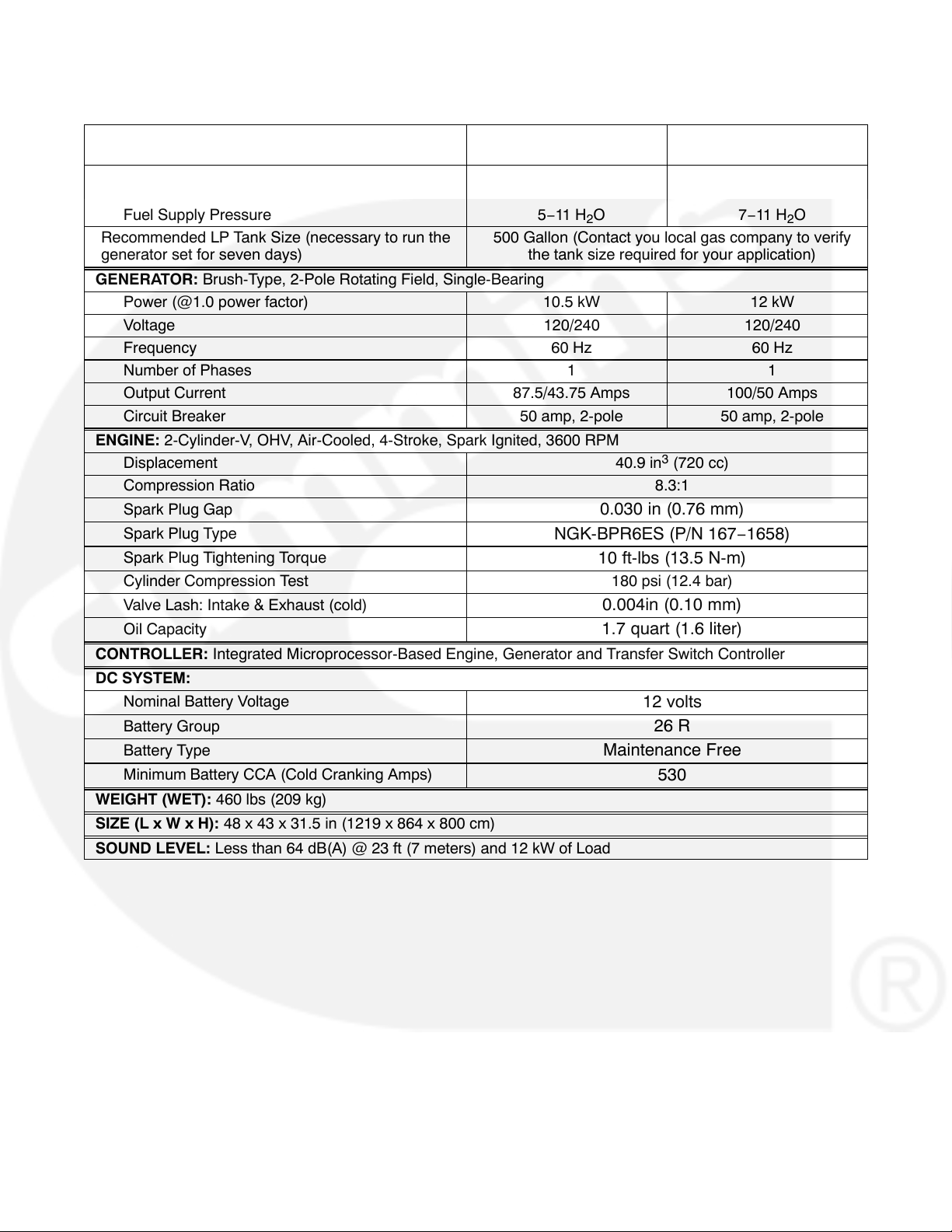
SPECIFICATIONS
FUEL CONSUMPTION:
@ 1/2 Load
@ Full Load
Fuel Supply Pressure
Recommended LP Tank Size (necessary to run the
generator set for seven days)
GENERATOR: Brush-Type, 2-Pole Rotating Field, Single-Bearing
Power (@1.0 power factor) 10.5 kW 12 kW
Voltage 120/240 120/240
Frequency 60 Hz 60 Hz
Number of Phases 1 1
Output Current 87.5/43.75 Amps 100/50 Amps
Circuit Breaker 50 amp, 2-pole 50 amp, 2-pole
ENGINE: 2-Cylinder-V, OHV, Air-Cooled, 4-Stroke, Spark Ignited, 3600 RPM
Displacement 40.9 in3 (720 cc)
Compression Ratio 8.3:1
Spark Plug Gap
Spark Plug Type
Spark Plug Tightening Torque
Cylinder Compression Test 180 psi (12.4 bar)
Valve Lash: Intake & Exhaust (cold)
Oil Capacity
CONTROLLER: Integrated Microprocessor-Based Engine, Generator and Transfer Switch Controller
DC SYSTEM:
Nominal Battery Voltage
Battery Group
Battery Type
Minimum Battery CCA (Cold Cranking Amps)
WEIGHT (WET): 460 lbs (209 kg)
SIZE (L x W x H): 48 x 43 x 31.5 in (1219 x 864 x 800 cm)
SOUND LEVEL: Less than 64 dB(A) @ 23 ft (7 meters) and 12 kW of Load
Natural Gas Installation
(1000 BTU/ft3)
122 ft3/hr (3.5 m3/hr)
191 ft3/hr (5.4 m3/hr)
5−11 H2O
500 Gallon (Contact you local gas company to verify
the tank size required for your application)
0.030 in (0.76 mm)
NGK-BPR6ES (P/N 167−1658)
10 ft-lbs (13.5 N-m)
0.004in (0.10 mm)
1.7 quart (1.6 liter)
12 volts
26 R
Maintenance Free
Propane Installation
(2500 BTU/ft3)
53 ft3/hr (1.5 m3/hr)
88 ft3/hr (2.5 m3/hr)
7−11 H2O
530
1-2
Page 11
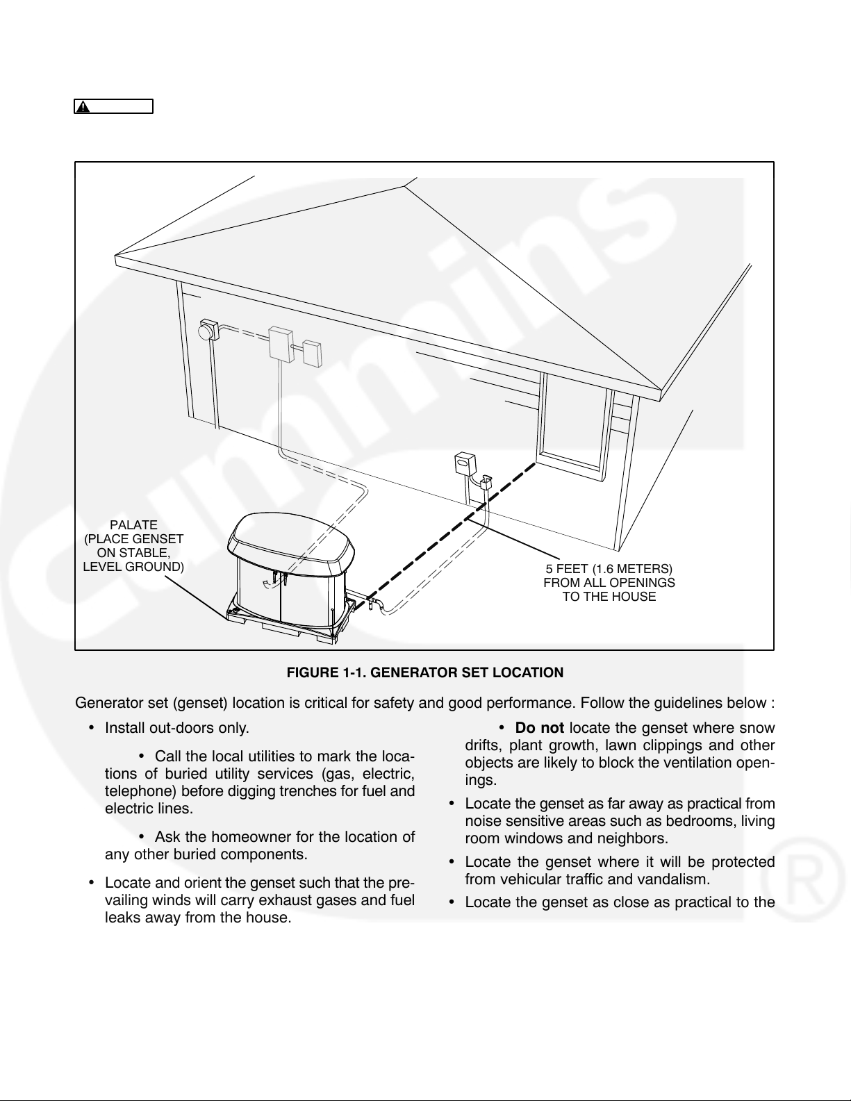
Generator Set Location
WARNING
doors, windows and other openings into the house and where the exhaust gases will disperse away
from the house.
EXHAUST GAS IS DEADLY! Install the generator set out-of-doors only, away from
PALATE
(PLACE GENSET
ON STABLE,
LEVEL GROUND)
FIGURE 1-1. GENERATOR SET LOCATION
5 FEET (1.6 METERS)
FROM ALL OPENINGS
TO THE HOUSE
Generator set (genset) location is critical for safety and good performance. Follow the guidelines below :
Install out-doors only.
Call the local utilities to mark the loca-
tions of buried utility services (gas, electric,
telephone) before digging trenches for fuel and
electric lines.
Locate the genset as far away as practical from
Do not locate the genset where snow
drifts, plant growth, lawn clippings and other
objects are likely to block the ventilation open-
ings.
noise sensitive areas such as bedrooms, living
Ask the homeowner for the location of
any other buried components.
Locate and orient the genset such that the pre-
vailing winds will carry exhaust gases and fuel
leaks away from the house.
Genset must be at least 5 feet (1.6 me-
ters) away from all openings to the house.
Do not locate the genset in a three-
sided niche of the house, under an overhang or
in a low-lying area or next to a basement.
room windows and neighbors.
Locate the genset where it will be protected
from vehicular traffic and vandalism.
Locate the genset as close as practical to the
house to reduce the lengths electric wiring and
fuel lines.
Place the genset on stable ground, not subject
to flooding.
Note: The area should be leveled and compacted with
sand or pea gravel.
1-3
Page 12
Natural Gas Supply
The Natural Gas supply meter may need to be exchanged for a higher capacity meter to supply the
additional gas consumed by the generator set. At
full load, the generator set alone requires 191,000
BTU/hr. To determine the required meter capacity,
generator set consumption must be added to the
gas consumed for heating, cooking, clothes drying,
etc. A typical installation might require a
400,000 BTU meter.
Consideration should also be given to utilizing high
pressure gas supply (2 psi), if available, to reduce
the required size, and therefore cost, of gas piping,
especially if the location of the generator set re-
quires a long supply line.
Note: The wire size varies, depending on distance (see Table 4-1).
10. Communications Wiring Connectors: Up to
twelve UL listed 18 AWG fork terminals for Item
9 wires (Cummins Part Number 0332−2527).
11. DC Conduit for Item 9 wires.
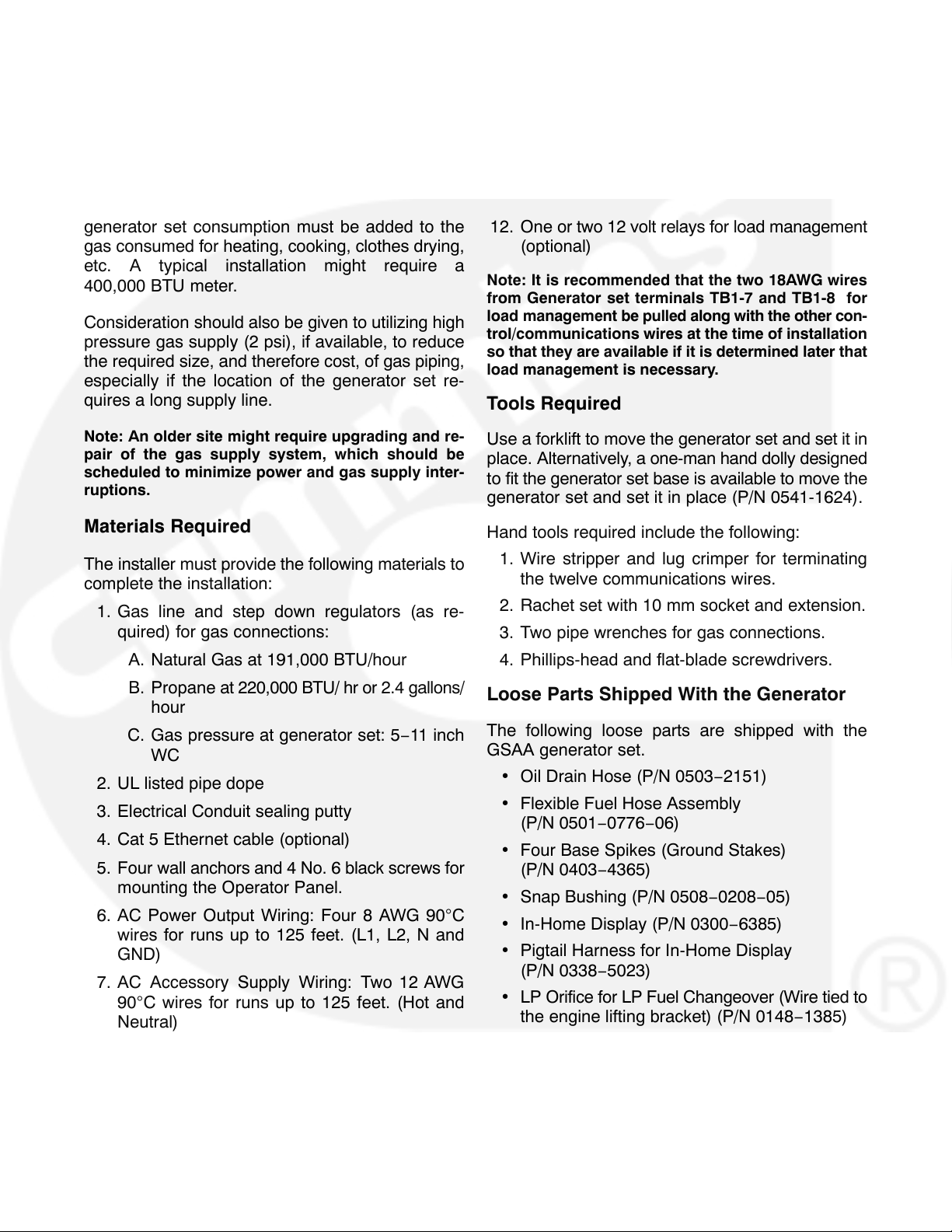
12. One or two 12 volt relays for load management
(optional)
Note: It is recommended that the two 18AWG wires
from Generator set terminals TB1-7 and TB1-8 for
load management be pulled along with the other con-
trol/communications wires at the time of installation
so that they are available if it is determined later that
load management is necessary.
Tools Required
Note: An older site might require upgrading and re-
pair of the gas supply system, which should be
scheduled to minimize power and gas supply inter-
ruptions.
Materials Required
The installer must provide the following materials to
complete the installation:
1. Gas line and step down regulators (as re-
quired) for gas connections:
A. Natural Gas at 191,000 BTU/hour
B. Propane at 220,000 BTU/ hr or 2.4 gallons/
hour
C. Gas pressure at generator set: 5−11 inch
WC
2. UL listed pipe dope
3. Electrical Conduit sealing putty
4. Cat 5 Ethernet cable (optional)
5. Four wall anchors and 4 No. 6 black screws for
mounting the Operator Panel.
6. AC Power Output Wiring: Four 8 AWG 90C
wires for runs up to 125 feet. (L1, L2, N and
GND)
7. AC Accessory Supply Wiring: Two 12 AWG
90C wires for runs up to 125 feet. (Hot and
Neutral)
8. AC Conduit for Items 6 and 7, which may be run
in the same conduit.
9. Control/Communications Wiring: Up to twelve
18 AWG wires, depending on Transfer Switch.
(Generator set TB1-1 through TB1-12)
Use a forklift to move the generator set and set it in
place. Alternatively, a one-man hand dolly designed
to fit the generator set base is available to move the
generator set and set it in place (P/N 0541-1624).
Hand tools required include the following:
1. Wire stripper and lug crimper for terminating
the twelve communications wires.
2. Rachet set with 10 mm socket and extension.
3. Two pipe wrenches for gas connections.
4. Phillips-head and flat-blade screwdrivers.
Loose Parts Shipped With the Generator
The following loose parts are shipped with the
GSAA generator set.
Oil Drain Hose (P/N 0503−2151)
Flexible Fuel Hose Assembly
(P/N 0501−0776−06)
Four Base Spikes (Ground Stakes)
(P/N 0403−4365)
Snap Bushing (P/N 0508−0208−05)
In-Home Display (P/N 0300−6385)
Pigtail Harness for In-Home Display
(P/N 0338−5023)
LP Orifice for LP Fuel Changeover (Wire tied to
the engine lifting bracket) (P/N 0148−1385)
Two Keys (P/N A026G567)
Quick Connect Guide (located in the battery
box)
Literature − Operator Manual, Installation
Manual, Setup Guide, and Warranty Statement
1-4
Page 13

INSTALLATION CODES AND STANDARDS
FOR SAFETY
WARNING
sole responsibility for following all applicable
local codes and regulations.
The following list of Installation Codes and Stan-
The generator set installer bears
TABLE 1-1. INSTALLATION CODES AND SAFETY RECOMMENDATIONS
dards for Safety applies to the installation and operation of standby generator sets. This list is for reference only and not intended to be inclusive of all
applicable codes and standards. The address of
each agency is listed so that copies of the codes
may be obtained for reference. Installation codes
and recommendations are subject to change, and
may vary by location or over time.
NFPA 70 National Electric Code
NFPA 37 Installation and Use of Stationary Combus-
tion Engines and Gas Turbines
NFPA 54 National Fuel Gas Code
NFPA 58 Storage and Handling of Liquefied Petro-
leum Gases
CSA Electrical Bulletin
CSA C22.2 No. 100
CSA C22.2 No. 14
California Administrative Code - Title 25 Chapter 3 State of California
Underwriters Laboratories
UL2200 Stationary Engine Generator Assemblies
National Fire Protection Association,
470 Atlantic Avenue
Boston, MA 02210
Canadian Standards Association,
Housing and Construction Materials Section
178 Rexdale Blvd.
Rexdale, Ontario, Canada M9W 1R3
Documents Section
P.O. Box 1015
North Highlands, CA 95660
Underwriters Laboratories, Inc.
333 Pfingsten Road
Northbrook, IL 60062-2096
1-5
Page 14

2. Step-by-Step Outline of Installation
INTRODUCTION
WARNING
plying with all applicable installation codes and
safety requirements.
This section is a step-by-step overview of a typical
installation. This section includes:
Locating the site
Generator set Clearances
Preparing the site
Moving the generator set
Placing the generator set
The installer is responsible for com-
Connecting the generator set
Review this section, then refer to the detailed in-
structions that are given in the following sections for
specific procedures and important safety precau-
tions before starting the installation.
LOCATING THE SITE
These generator sets are housed in a weather-pro-
tective enclosure for installation out-of-doors on a
non-combustible base.
Choose a site close to the electric service and Natu-
ral Gas meter or Propane tank. The main distribu-
tion, transfer switch, and sub-panels are usually in-
side the house.
ELECTRIC
METER
GENERATOR
UNDERGROUND
ELECTRIC
SERVICE
SET
TRANSFER
SWITCH
DISTRIBUTION
PANEL
GAS
METER
GAS
SHUTOFF
VALVE
UNDERGROUND
GAS SERVICE
FIGURE 2-1. TYPICAL GENERATOR SET SITE
2-1
Page 15
GENERATOR SET CLEARANCES
The generator set must be a minimum of 3 ft
(915 mm) from combustible material (NFPA 37).
Leave at least 3 ft (915 mm) all around the generator set enclosure for access to the inside (NEC Art.
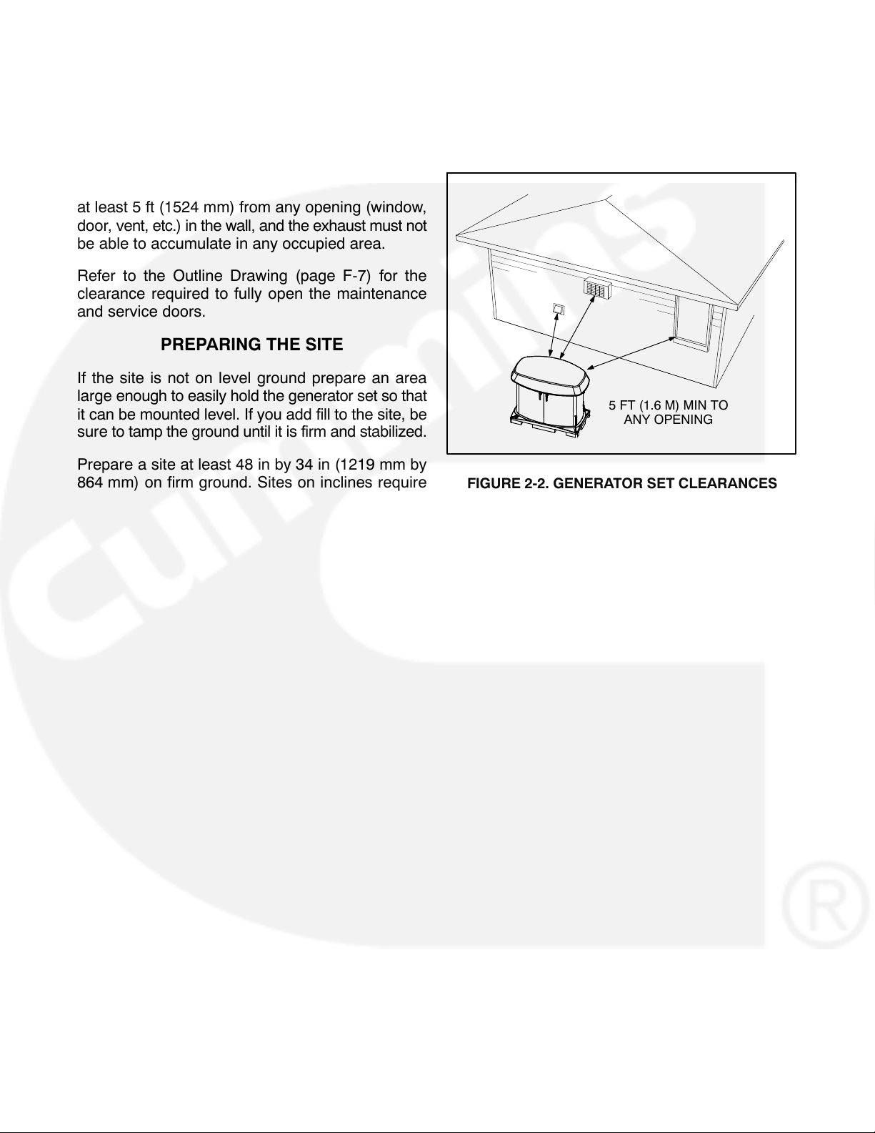
110-26a, Art. 110-26b). The generator set must be
at least 5 ft (1524 mm) from any opening (window,
door, vent, etc.) in the wall, and the exhaust must not
be able to accumulate in any occupied area.
Refer to the Outline Drawing (page F-7) for the
clearance required to fully open the maintenance
and service doors.
PREPARING THE SITE
If the site is not on level ground prepare an area
large enough to easily hold the generator set so that
it can be mounted level. If you add fill to the site, be
sure to tamp the ground until it is firm and stabilized.
Prepare a site at least 48 in by 34 in (1219 mm by
864 mm) on firm ground. Sites on inclines require
more area. Add a layer of sand or pea gravel deep
enough so that you can level the generator set. Remove any combustible material that would be under
and around the generator set.
5 FT (1.6 M) MIN TO
ANY OPENING
FIGURE 2-2. GENERATOR SET CLEARANCES
2-2
Page 16
LIFTING AND MOVING GENERATOR SET
WARNING
ping the generator set can cause severe personal injury or death. Keep feet and hands clear
when lifting the generator set.
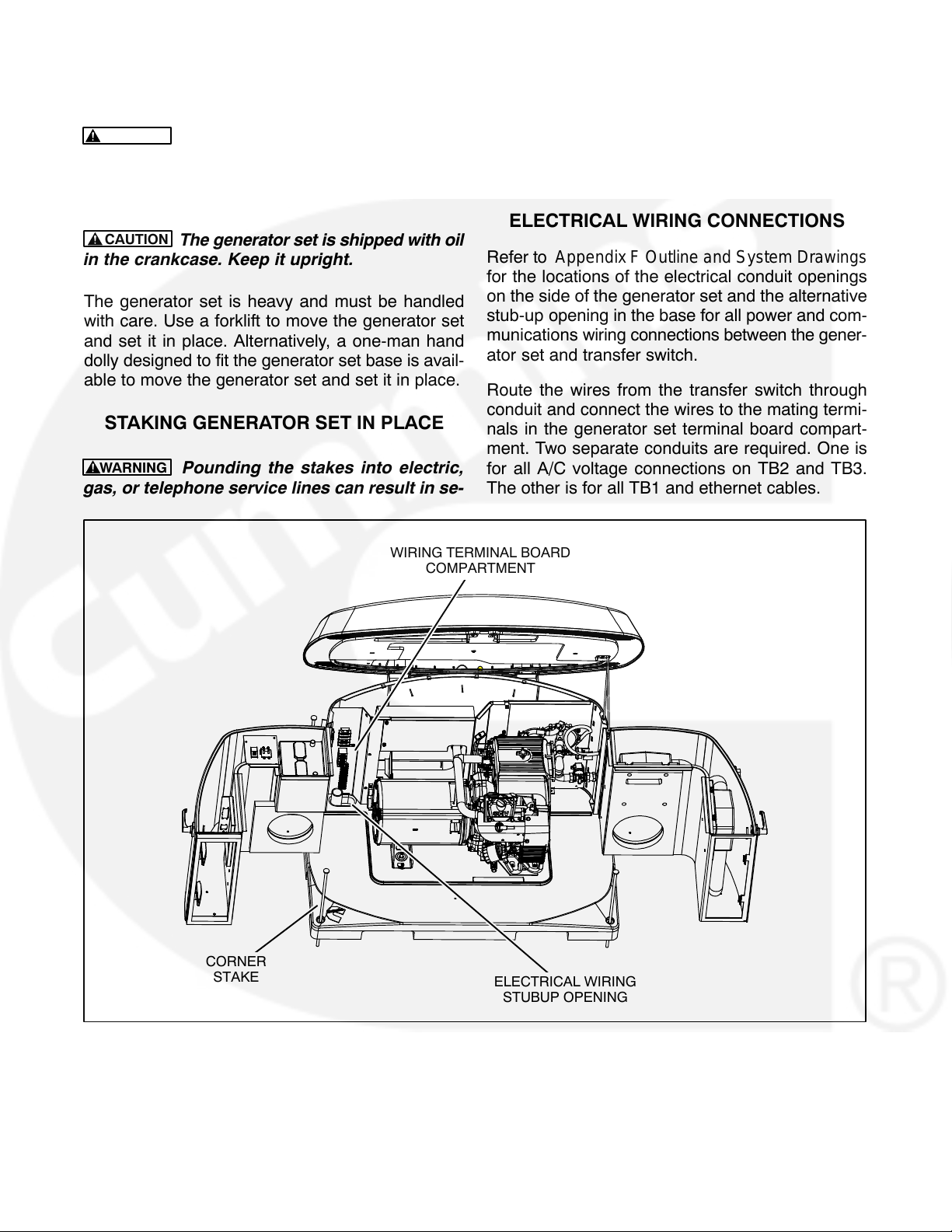
CAUTION
in the crankcase. Keep it upright.
The generator set is heavy and must be handled
with care. Use a forklift to move the generator set
and set it in place. Alternatively, a one-man hand
dolly designed to fit the generator set base is avail-
able to move the generator set and set it in place.
The generator set is heavy. Drop-
The generator set is shipped with oil
STAKING GENERATOR SET IN PLACE
WARNING
gas, or telephone service lines can result in se-
Pounding the stakes into electric,
vere personal injury or death. Observe the utility
company markings.
Set the generator set in place and pound the four
corner stakes into the ground to secure the generator set in place.
ELECTRICAL WIRING CONNECTIONS
Refer to Appendix F Outline and System Drawings
for the locations of the electrical conduit openings
on the side of the generator set and the alternative
stub-up opening in the base for all power and com-
munications wiring connections between the gener-
ator set and transfer switch.
Route the wires from the transfer switch through
conduit and connect the wires to the mating termi-
nals in the generator set terminal board compart-
ment. Two separate conduits are required. One is
for all A/C voltage connections on TB2 and TB3.
The other is for all TB1 and ethernet cables.
CORNER
STAKE
WIRING TERMINAL BOARD
COMPARTMENT
ELECTRICAL WIRING
STUBUP OPENING
FIGURE 2-3. ELECTRICAL WIRING TERMINAL BOARDS AND STUBUP OPENING
2-3
Page 17
GAS LINE CONNECTIONS
WARNING
explosion that can result in severe personal injury or death. Do not smoke or allow any flame,
spark, pilot light, or other ignition sources near
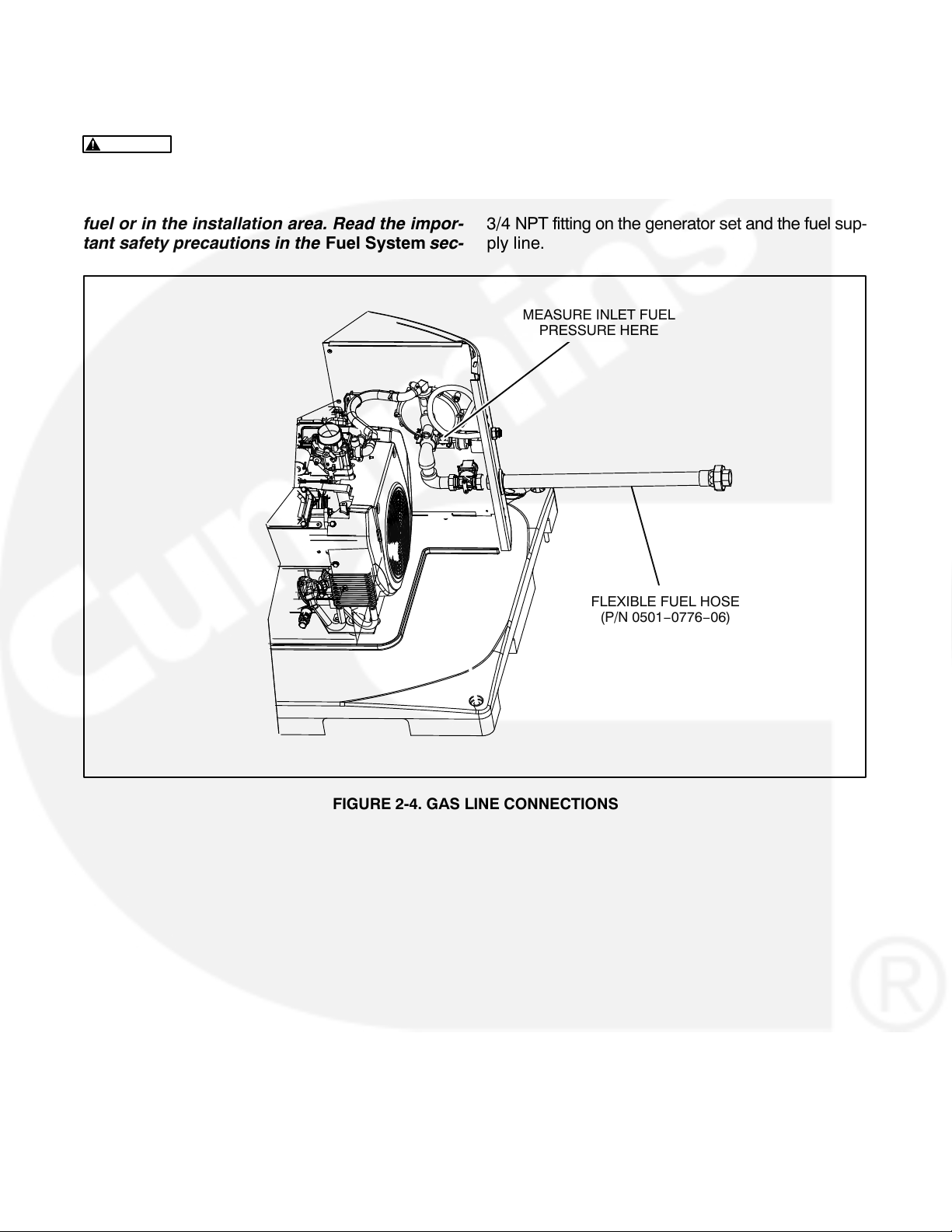
fuel or in the installation area. Read the impor-
tant safety precautions in the Fuel System sec-
Fuel presents the hazard of fire or
tion.
Refer to Appendix F Outline and System Drawings
for the location of the fuel supply connection through
the side of the generator set. A flexible fuel hose is
packaged inside the generator set (Assembly part
number: 0501−0776−06). Connect it between the
3/4 NPT fitting on the generator set and the fuel sup-
ply line.
MEASURE INLET FUEL
PRESSURE HERE
FLEXIBLE FUEL HOSE
(P/N 0501−0776−06)
FIGURE 2-4. GAS LINE CONNECTIONS
2-4
Page 18
3. Mechanical
LOCATION AND ACCESS
These generator sets are designed for installation
out-of-doors in its weather-protective enclosure.
Factors to consider when deciding where to locate
the generator set include:
Proximity of generator set, transfer switch,
loads and Natural Gas fuel lines or Propane
tanks.
Access for maintenance and service. Refer to
the Outline Drawing (page F-7) for the clear-
ance required to fully open the maintenance
and service doors.
Security from vandalism, flooding and vehicu-
lar traffic.
Noise levels and proximity of property lines.
Safe dispersal of engine exhaust and cooling
air away from buildings, habitable areas, and
people.
Possible obstructions to ventilation caused by
snowdrifts, plant growth, lawn clippings, falling
leaves, etc.
See Locating the Site in Section 2.
FUEL SYSTEM
WARNING
qualified service technicians. Improper installa-
tion presents hazards of fire and improper op-
eration, resulting in severe personal injury or
property damage.
The generator set name plate is marked to indicate
the fuel type, Natural Gas or Propane.
WARNING
explosive and can cause severe personal injury
or death. Do not smoke if you smell gas or are
near fuel tanks or fuel-burning equipment or are
in an area sharing ventilation with such equip-
ment. Keep flames, sparks, pilot lights, electri-
cal arcs and arc-producing equipment and all
other sources of ignition well away. Keep a type
ABC fire extinguisher handy.
In all fuel system installations, cleanliness is of the
upmost importance. Make every effort to prevent
entrance of moisture, dirt, excess thread sealant, or
contaminants of any kind. Clean all fuel system
components before installing.
Fuel systems must be installed by
Gaseous fuels are flammable and
ENGINE EXHAUST
The exhaust system of this generator set was de-
signed for this engine and is complete. Do not
modify or add to the exhaust system of this genera-
tor set.
WARNING
haust system must terminate away from build-
ing vents, windows and doors and sheltered
spaces that may not have ample fresh air ven-
tilation.
Do not use generator set discharge air or engine ex-
haust for heating a room or enclosed space.
WARNING
carry carbon monoxide gas (odorless and invisible) which can cause asphyxiation and death.
Never use engine discharge air or exhaust for
heating a room or enclosed space.
EXHAUST GAS IS DEADLY! The ex-
Engine discharge air and exhaust
The section of flexible fuel hose supplied with the
generator set must be used between the engine’s
fuel system and fuel supply line to protect the fuel
system from damage caused by vibration, expan-
sion and contraction. The fuel hose must be
installed according to all applicable codes and stan-
dards.
Gaseous-fuel supply system design, materials,
components, fabrication, assembly, installation,
testing, inspection, operation and maintenance
must comply with the applicable codes. See NFPA
Standards No. 37, No. 54, and No. 58.
Most codes require a manual shutoff valve ahead of
a flexible fuel hose. The manual valve should be of
the indicating type. The generator set has an electric (battery-powered) shutoff valve included between the fuel supply and the carburetor.
Until the generator set is connected, cap the fuel line
stub-up at the generator set to prevent dirt from en-
3-1
Page 19
tering and gas discharging if the gas supply shutoff
valve is opened inadvertently.
Refer to Appendix E. Specifications for the fuel inlet
size.
NATURAL GAS FUEL SYSTEM
(191 cubic feet/hr) delivered to the generator set inlet at 5−11 inches (28 mm) WC (Water Column). If
the meter serves other gas appliances such as a furnace, water heater, or stove, you must consult with
the local Natural Gas utility to determine whether
the Natural Gas meter is adequate.
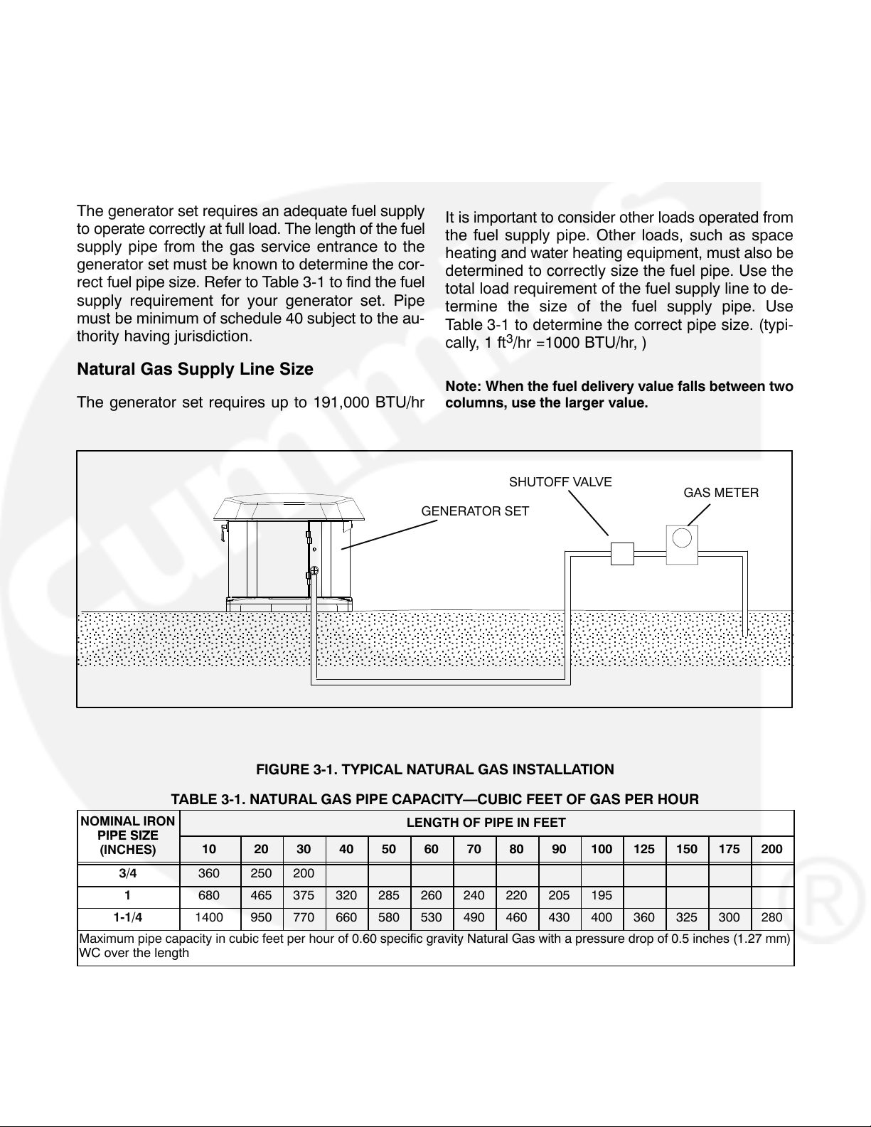
The generator set requires an adequate fuel supply
to operate correctly at full load. The length of the fuel
supply pipe from the gas service entrance to the
generator set must be known to determine the cor-
rect fuel pipe size. Refer to Table 3-1 to find the fuel
supply requirement for your generator set. Pipe
must be minimum of schedule 40 subject to the au-
thority having jurisdiction.
Natural Gas Supply Line Size
The generator set requires up to 191,000 BTU/hr
It is important to consider other loads operated from
the fuel supply pipe. Other loads, such as space
heating and water heating equipment, must also be
determined to correctly size the fuel pipe. Use the
total load requirement of the fuel supply line to de-
termine the size of the fuel supply pipe. Use
Table 3-1 to determine the correct pipe size. (typi-
cally, 1 ft
Note: When the fuel delivery value falls between two
columns, use the larger value.
GENERATOR SET
3
/hr =1000 BTU/hr, )
SHUTOFF VALVE
GAS METER
FIGURE 3-1. TYPICAL NATURAL GAS INSTALLATION
TABLE 3-1. NATURAL GAS PIPE CAPACITY—CUBIC FEET OF GAS PER HOUR
NOMINAL IRON
PIPE SIZE
(INCHES)
3/4 360 250 200
1 680 465 375 320 285 260 240 220 205 195
1-1/4 1400 950 770 660 580 530 490 460 430 400 360 325 300 280
Maximum pipe capacity in cubic feet per hour of 0.60 specific gravity Natural Gas with a pressure drop of 0.5 inches (1.27 mm)
WC over the length
10 20 30 40 50 60 70 80 90 100 125 150 175 200
LENGTH OF PIPE IN FEET
3-2
Page 20
PROPANE FUEL SYSTEM
WARNING
NFPA Standard No. 58 requires all
persons handling and operating Propane to be
trained in proper handling and operating procedures.
WARNING
Fuel leaks can lead to explosive ac-
cumulations of gas. Propane sinks in air and
can accumulate inside housings, basements
and other below-grade spaces. Prevent gas
leaks and the accumulation of gaseous fuel in
the event of a leak.
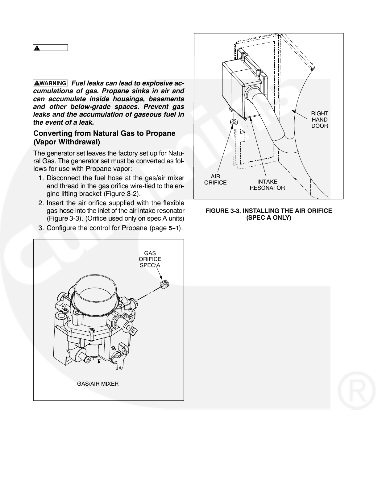
Converting from Natural Gas to Propane
(Vapor Withdrawal)
The generator set leaves the factory set up for Natu-
ral Gas. The generator set must be converted as fol-
lows for use with Propane vapor:
1. Disconnect the fuel hose at the gas/air mixer
and thread in the gas orifice wire-tied to the en-
gine lifting bracket (Figure 3-2).
2. Insert the air orifice supplied with the flexible
gas hose into the inlet of the air intake resonator
(Figure 3-3). (Orifice used only on spec A units)
3. Configure the control for Propane (page
5−1).
RIGHT
HAND
DOOR
AIR
ORIFICE
FIGURE 3-3. INSTALLING THE AIR ORIFICE
INTAKE
RESONATOR
(SPEC A ONLY)
GAS
ORIFICE
SPEC A
GAS/AIR MIXER
FIGURE 3-2. INSTALLING THE PROPANE GAS
ORIFICE
3-3
Page 21
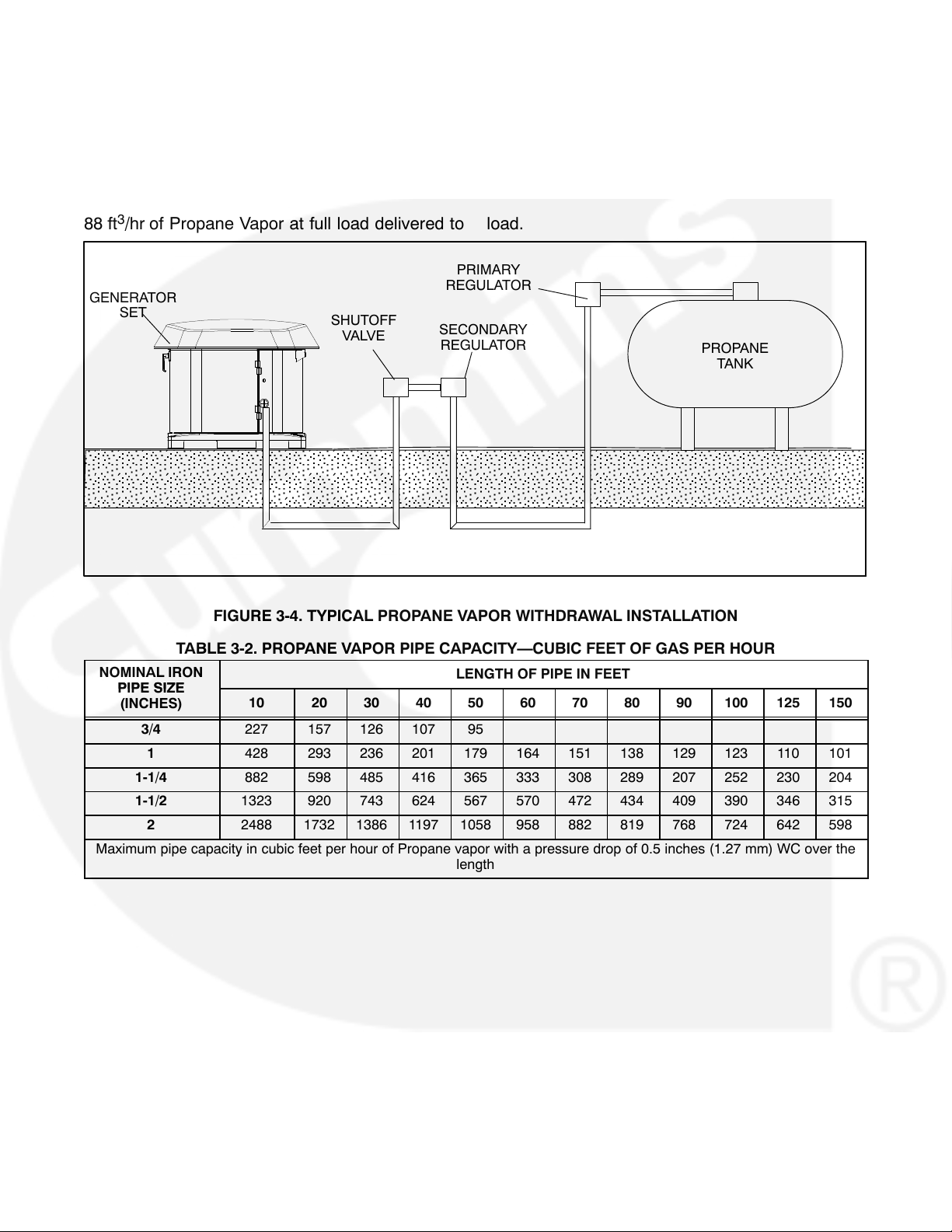
Propane Vapor Fuel Supply Line Size and
Pressure
Fuel line size depends on the amount of fuel needed
to run the generator set at full load at the distance
the fuel must be moved. The generator set requires
3
88 ft
/hr of Propane Vapor at full load delivered to
GENERATOR
SET
SHUTOFF
VALVE
REGULATOR
SECONDARY
REGULATOR
the generator set inlet at 7−11 inches WC (Water
Column) gas pressure. Figure 3-4 shows a typical
Propane Vapor installation and Table 3-2 lists fuel
capacity for given distances and pipe size.
Size the fuel line so that the Propane vapor pressure
drops no more than 2 inches WC from no load to full
load.
PRIMARY
PROPANE
TANK
FIGURE 3-4. TYPICAL PROPANE VAPOR WITHDRAWAL INSTALLATION
TABLE 3-2. PROPANE VAPOR PIPE CAPACITY—CUBIC FEET OF GAS PER HOUR
NOMINAL IRON
PIPE SIZE
(INCHES)
3/4 227 157 126 107 95
1 428 293 236 201 179 164 151 138 129 123 110 101
1-1/4 882 598 485 416 365 333 308 289 207 252 230 204
1-1/2 1323 920 743 624 567 570 472 434 409 390 346 315
2 2488 1732 1386 1197 1058 958 882 819 768 724 642 598
Maximum pipe capacity in cubic feet per hour of Propane vapor with a pressure drop of 0.5 inches (1.27 mm) WC over the
10 20 30 40 50 60 70 80 90 100 125 150
LENGTH OF PIPE IN FEET
length
3-4
Page 22
Fuel Pressure
WARNING
cause gas leaks which can lead to fire and severe personal injury or death. Gas supply pressure must be adjusted to Specifications by
trained and experienced personnel.
Satisfactory performance requires that the Propane
Vapor be supplied at a pressure within the range of
7-11 inches WC (water column).
When measuring supply pressure, the most accu-
rate reading would be on the input side of the sole-
noid valve.
High gas supply pressure can
Recommended Fuel
Use clean, fresh HD-5 grade Propane or equivalent
product consisting of at least 90 percent Propane.
Commercial Propane may contain more than 2.5
percent butane which can result in poor fuel vapor-
ization and low tank pressure resulting in poor en-
gine starting in low ambient temperatures (below
32F (0C).
WARNING
or explosion that can cause severe personal in-
jury or death. Do not permit any flame, spark,
Propane presents the hazard of fire
arc-producing equipment, switch, pilot light,
cigarette, or other ignition source near the fuel
system. Keep an ABC type fire extinguisher
nearby.
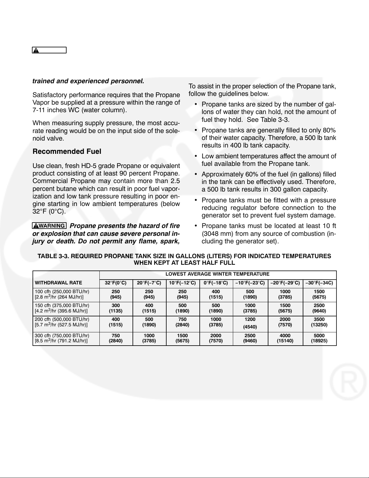
Propane Tank Size
To assist in the proper selection of the Propane tank,
follow the guidelines below.
Propane tanks are sized by the number of gal-
lons of water they can hold, not the amount of
fuel they hold. See Table 3-3.
Propane tanks are generally filled to only 80%
of their water capacity. Therefore, a 500 lb tank
results in 400 lb tank capacity.
Low ambient temperatures affect the amount of
fuel available from the Propane tank.
Approximately 60% of the fuel (in gallons) filled
in the tank can be effectively used. Therefore,
a 500 lb tank results in 300 gallon capacity.
Propane tanks must be fitted with a pressure
reducing regulator before connection to the
generator set to prevent fuel system damage.
Propane tanks must be located at least 10 ft
(3048 mm) from any source of combustion (in-
cluding the generator set).
TABLE 3-3. REQUIRED PROPANE TANK SIZE IN GALLONS (LITERS) FOR INDICATED TEMPERATURES
WHEN KEPT AT LEAST HALF FULL
LOWEST AVERAGE WINTER TEMPERATURE
WITHDRAWAL RATE 32F(0C) 20F(−7C) 10F(−12C) 0F(−18C) −10F(−23C) −20F(−29C) −30F(−34C)
100 cfh (250,000 BTU/hr)
[2.8 m3/hr (264 MJ/hr)]
150 cfh (375,000 BTU/hr)
[4.2 m3/hr (395.6 MJ/hr)]
200 cfh (500,000 BTU/hr)
[5.7 m3/hr (527.5 MJ/hr)]
300 cfh (750,000 BTU/hr)
[8.5 m3/hr (791.2 MJ/hr)]
250
(945)
300
(1135)
400
(1515)
750
(2840)
250
(945)
400
(1515)
500
(1890)
1000
(3785)
250
(945)
500
(1890)
750
(2840)
1500
(5675)
400
(1515)
500
(1890)
1000
(3785)
2000
(7570)
500
(1890)
1000
(3785)
1200
(4540)
2500
(9460)
1000
(3785)
1500
(5675)
2000
(7570)
4000
(15140)
1500
(5675)
2500
(9640)
3500
(13250)
5000
(18925)
3-5
Page 23

Testing Fuel System for Leaks
Before operating the set, test the Propane fuel system for leaks. Energize the fuel solenoid from a separate 12-volt DC source before testing the fuel system. Testing must conform to procedures listed in
NFPA-58, or to the UL recommended test procedure, as follows:
After assembly and before initial operation, all fuel
system connections, hose valves, regulators, and
fittings must be tested and proven free of leaks us-
ing a soap-and-water (or equivalent) solution while
the system is under gas or air pressure of at least
1.5 times the supply pressure or 3 psi (20.7 kPa)
minimum.
Other approved methods of detecting leaks can be
used if appropriate. DO NOT use a flame to test for
gas leaks.
WARNING
plosion or fire which can result in severe per-
sonal injury or death. Do not smoke or allow any
flame, spark, pilot light, arc-producing equip-
ment, switch, or other ignition sources around
fuel or fuel components.
Propane presents the hazard of ex-
3-6
Page 24
4. Electrical Connections
AC POWER SUPPLY CONNECTIONS
WARNING
made by a licenced electrician. Improper instal-
lation can lead to electrocution and damage to
property.
Automatic startup of the generator set during
installation can cause severe personal injury or
death. Push the control switch Off and discon-
nect the negative (−) cable from the battery to
keep the generator set from starting.
Electrical connections must be
Wiring
Refer to the requirements of The National Electrical
Code (NFPA No. 70) for all AC wiring connections.
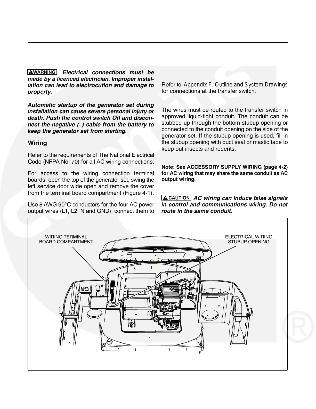
For access to the wiring connection terminal
boards, open the top of the generator set, swing the
left service door wide open and remove the cover
from the terminal board compartment (Figure 4-1).
Use 8 AWG 90C conductors for the four AC power
output wires (L1, L2, N and GND), connect them to
the AC output terminal board (TB-2). Torque the
termninals to 25 lb−inch (2.8 N−m).
Refer to Appendix F. Outline and System Drawings
for connections at the transfer switch.
The wires must be routed to the transfer switch in
approved liquid-tight conduit. The conduit can be
stubbed up through the bottom stubup opening or
connected to the conduit opening on the side of the
generator set. If the stubup opening is used, fill in
the stubup opening with duct seal or mastic tape to
keep out insects and rodents.
Note: See ACCESSORY SUPPLY WIRING (page 4-2)
for AC wiring that may share the same conduit as AC
output wiring.
CAUTION
in control and communications wiring. Do not
route in the same conduit.
AC wiring can induce false signals
WIRING TERMINAL
BOARD COMPARTMENT
ELECTRICAL WIRING
STUBUP OPENING
FIGURE 4-1. WIRING TERMINAL BOARDS
4-1
Page 25
ACCESSORY SUPPLY CONNECTIONS
To supply 120 VAC to power the GFCI outlet on the
side of the generator set, optional battery heater
(P/N 0333−0770) and optional engine oil and carburetor heater (P/N 0333-0771), connect two 12 AWG
90C wires to generator set terminal block TB3 (Hot
and Neutral) from a 15 amp protected circuit in the
main distribution panel in the house. The wires may
be run through the same conduit as the power sup-
ply wires.
Grounding
The generator set, transfer switch, power supply
wiring, and all connected electrical equipment must
be bonded to a common grounding point in accor-
dance with applicable codes or standards (Figure
4-2).
WARNING
The generator set grounding terminal (TB2-4) must be connected to the grounding
terminal in the transfer switch. Do not provide a
separate grounding rod for the generator set.
Note that generator neutral is not grounded at the
generator set, but at the common system grounding
point.
WARNING
Contact with electrical equipment
can result in severe personal injury or death. It is
extremely important that bonding and equip-
ment grounding be properly done. All metallic
parts that could become energized under ab-
normal conditions must be properly grounded.
4-2
Page 26

GROUNDING WITH MODEL RSS 100−6634 AND RSS 200−6635 TRANSFER SWITCHES
SERVICE ENTRANCE
2-POLE TRANSFER
SWITCH
L
TO UTILITY
SERVICE
GROUNDING WITH MODEL RSS 100−6868 AND RSS 200−6869 TRANSFER SWITCHES
N
LOADS
COMBINED SERVICE-ENTRANCE AND
2-POLE TRANSFER SWITCH
L
GENERATOR SET
GENERATOR SET
TO UTILITY
SERVICE
N
LOADS
FIGURE 4-2. TYPICAL SYSTEM GROUNDING ONE-LINE DIAGRAMS
4-3
Page 27

Transfer Switch
O
WARNING
and the public utility can lead to the electrocution of personnel working on the utility lines,
damage to equipment and fire. An approved
switching device must be used to prevent interconnections.
Interconnecting the generator set
TABLE 4-1. WIRE SIZE SPECIFICATIONS
Wire Size
(AWG)
16 90
14 150
12 225
Distance in Feet, One Way
(Multiply by 0.3 for Meters)
The Model GSAA generator set is designed to be
installed with Cummins Onan Model RSS automatic
transfer switches. Use of other makes and models
of transfer switches with the Model GSAA generator
will result in a reduced warranty. Reference the War-
ranty statement for further details.
Install the transfer switch in accordance with its
Installation Manual. Refer to Appendix F. Outline
and System Drawings for wiring connections be-
tween the generator set and transfer switch.
See Wiring (page 4-1) regarding wiring to use for
AC power output connections between the genera-
tor set and transfer switch.
Use 18 AWG conductors for the control/commu-
nications wires (generator set TB1 to transfer switch
terminal TB4). It is recommended that all twelve
conductors (nine conductors for RSS 100−6634
and RSS 200−6635) be pulled through the conduit
at the time of installation to be ready for functions
that might be activated later, such as load control.
Note: The wire used must be sized to accommodate
any specific voltage drop. Refer to Table 4-1 to deter-
mine the correct wire size.
10 350
8 600
6 1000
Block diagrams showing partial or full load coverage
are shown on the following pages. Figures 4-3 and
4-4 show installations without a controller (RSS
100-6634 and RSS 200−6635) and Figures 4-5 and
4-6 show installations with a controller (RSS
100−6868 and RSS 200−6869). The RSS100 trans-
fer switch models can be connected for full or partial
load coverage equal to the capacity of the generator
set. The RSS200 transfer switch models can be
connected for full load coverage greater than the ca-
pacity of the generator set. If the transfer switch is
connected for full load coverage which exceeds
generator set rating, it may be necessary to shed
large loads such as air conditioners. Refer to Ap-
pendix F. Outline and System Drawings for con-
necting load shed relays to generator set load con-
trol terminals TB1−1 and TB1-2.
TABLE 4-2. TITLE???
CONNECTION CAPABILITIES
TRANSFER SWITCH MODEL FULL LOAD
RSS 100−6634 X
RSS 200−6635 X
RSS 100−6868 X
RSS 200−6869 X
1. XXXXXXXXXXXXXXXXXXXXXXXXXXXX
Note: Model RSS100−6634 and RSS200−6635 Transfer Switches do not incorporate a utility circuit breaker and therefore must be connected through a Service Entrance Utility Panel incorporating the utility
(GREATER THAN
CAPACITY OF GENSET)
circuit breaker.
Perform GENERATOR SET CONFIGURATION
(page 5-1) when ready start up the generator set.
4-4
FULL OR PARTIAL LOAD
(EQUAL T
CAPACITY OF GENSET)
Page 28

UTILITY PANEL
UTILITY
SOURCE
LOADS
TRANSFER SWITCH
CIRCUIT
BREAKER
CIRCUIT
BREAKER
DISTRIBUTION PANEL
GENERATOR
SOURCE
LOADS
FIGURE 4-3. PARTIAL COVERAGE LOAD CONNECTIONS (TRANSFER SWITCH WITHOUT CONTROLLER)
TRANSFER SWITCH*
UTILITY
SOURCE
CIRCUIT
BREAKER
CIRCUIT
BREAKER
GENERATOR
SOURCE
MAIN
BREAKER
PANEL
ALL LOADS
FIGURE 4-4. FULL COVERAGE LOAD CONNECTIONS (TRANSFER SWITCH WITHOUT CONTROLLER,
ONE CIRCUIT BREAKER)
4-5
Page 29

UTILITY PANEL
UTILITY
SOURCE
LOADS
TRANSFER SWITCH
CIRCUIT
BREAKER
DISTRIBUTION PANEL
GENERATOR
SOURCE
LOADS
FIGURE 4-5. PARTIAL COVERAGE LOAD CONNECTIONS (TRANSFER SWITCH WITH CONTROLLER)
TRANSFER SWITCH
UTILITY
SOURCE
CIRCUIT
BREAKER
CIRCUIT
BREAKER
GENERATOR
SOURCE
MAIN
BREAKER
PANEL
ALL LOADS
FIGURE 4-6. FULL COVERAGE LOAD CONNECTIONS (TRANSFER SWITCH WITH CONTROLLER)
4-6
Page 30

OPERATOR PANEL
See the Operator Manual for operating and monitoring the generator set using the Operator Panel.
Mount the generator set Operator Panel on a wall at
a convenient location, such as next to the house
thermostat. To install the Operator Panel cut out an
opening in the wall as shown in Figure 4-7 and
mount it with four No. 6 wood screws or wall anchors.
Refer to Appendix F. Outline and System Drawings
for connecting the Operator Panel to the generator
set. Use the plug-in connection harness (shipped
loose with the generator set) to connect to the wiring
from the generator set. Use 18 AWG wires.
WALL CUTOUT
PLUG-IN CONNECTION HARNESS
FIGURE 4-7. CUTOUT FOR OPERATOR PANEL AND CONNECTION HARNESS
4-7
Page 31

ETHERNET CONNECTIONS (OPTIONAL)
The generator set control board has a connector for
Cat 5 Ethernet cable for connection to a remote mo-
dem/router. See Appendix B. Ethernet/Email Inter-
face for setup and operation.
along with other wiring from the control to the wiring
terminal board compartment and then into the conduit to the house.
Note: The Internet/Email interface requires “high
speed” or “broadband” cable or DSL service to the
house.
Use Cat 5 Ethernet cable and route it separately into
the house or along with the control/communications
wiring. At the generator set route the Cat 5 cable
ETHERNET
CONNECTOR ON
CONTROL BOARD
Wiring connections to the Ethernet RJ-45 plug are
shown in Figure 4-9. Utilize an appropriate Ethernet
stripping and crimping tool for these connections.
PIN 1
g = Green and White
G = Green
o = Orange and White
O = Orange
b = Blue and White
B = Blue
br = Brown and White
BR = Brown
FIGURE 4-8. ETHERNET CONNECTOR
FIGURE 4-9. ETHERNET RJ-45 CONNECTOR WIRING
4-8
Page 32

BATTERY
The generator set has a 12 VDC, negative-ground
control and engine cranking system. The engine
has a battery charger for recharging during generator set operation. A battery charger located in the
transfer switch keeps the battery charged during
generator set standby.
Install the heater in accordance with the kit instructions.
To prevent injury due to accidental start-up, do not
connect the battery cables to the battery until the
installation has been completed and it is time to start
the set. See Section 5. Installation Review and
Startup
Refer to Appendix E. Specifications regarding bat-
tery specifications.
An optional thermostatically controlled battery heat-
er is available for more reliable starting in ambient
temperatures down to −20 F (−28.8 C). The heat-
er wraps around the battery. The heater cord is con-
nected to the 120V, accessory connection block.
BATTERY
WARNING
Automatic startup of the generator
set while performing maintenance or service
can cause severe personal injury or death. Push
the control switch to Off and disconnect the
negative (−) battery cable from the battery to
keep the generator set from starting up while
working on it.
FIGURE 4-10. BATTERY INSTALLATION
4-9
Page 33

5. Startup and Configuration
INSTALLATION REVIEW
Before starting the genset inspect the installation
and check off () each of the following questions if it
can be answered “YES”. If a question cannot be
checked off, review the appropriate section in the
manual.
[ ] Can the top and the maintenance and service
access doors be swung fully open for opera-
tion, maintenance and service?
[ ] Are the cooling air inlet and outlet openings
free of obstructions?
[ ] Have the AC output connections been made
properly?
[ ] Has the transfer switch been installed properly
to prevent connecting the generator set to the
utility?
[ ] Has a properly sized battery been installed?
[ ] Are all fuel connections tight?
[ ] Is fuel supply pressure correct?
[ ] Are electrical and fuel lines properly sepa-
rated?
[ ] Does engine exhaust disperse away from
buildings?
STARTUP
genset, following all the instructions and precautions in the Operator Manual.
Perform GENERATOR SET CONFIGURATION
(page 5-1).
Note: Before leaving the site, if the genset is ready to
be placed in service, set the control switch to the
AUTO position to provide automatic standby power.
GENERATOR SET CONFIGURATION
The Operator Panel has a menu with four generator
set/transfer switch parameters that must be config-
ured for the installation.
Generator Configuration
To configure the generator set:
1. Press the MENU button on the home screen.
2. Press and hold the blank button on the menu
screen for at least 5 seconds to go to the Con-
fig Menu.
3. Press the up or down arrow button on the Con-
fig Menu screen to select Generator Config.
4. Press Enter on the Config Menu to go to the
Generator Config screen.
5. Press the NEXT button on the Generator Con-
fig Menu screen to select the Config, Frequen-
cy or Rating field.
When all installation requirements have been met,
connect the battery cables to the battery, positive
(+) cable first.
WARNING
set during installation can cause severe per-
sonal injury or death. Push the control switch
Off and disconnect the negative (−) cable from
the battery to keep the generator set from start-
ing.
Read through the Operator’s Manual and perform
the maintenance and pre-start checks instructed.
The genset is shipped from the factory with the
proper level of engine oil, but should be checked
before the genset is started. Start and operate the
Automatic startup of the generator
6. Press the up or down arrow button to increase
or decrease the configuration parameter.
A. Config: Select “12” for Natural Gas or “13”
for Propane.
B. Frequency: “60” Hz cannot be changed at
this time.
C. Rating: Select “50” Amps for Propane or
“43” Amps for Natural Gas. Select lower
values if it is necessary to derate for high
altitude or hot climates. (Selecting the correct Amps value is necessary for displaying the correct genset load on the Operator Panel.
7. Press the BACK button to save the setting and
return to the home screen.
5-1
Page 34

Sun 10:35 AM
Battery 12.5
GENERATOR ADJUSTMENTS
Refer to Figure 5-2. To adjust the Operator Panel
voltage display and hour meter, access the Adjustment Menu Screen as follows:
1. Press the MENU button on the home screen.
Genset Load
L1 L2
EXCER
Genset Status
Display Setup
Event Log
Fault Log
Ethernet Setup
hold blank button
for 5 seconds
Config Menu
Generator Config
Generator Adjustments
TS Config
TS Adjustments
MENUCLOCK LOAD
ENTER
ENTER
2. Press and hold the blank button on the menu
screen for at least 5 seconds to go to the Con-
fig Menu.
3. Press the up or down arrow button on the Con-
fig Menu screen to select Generator Adjust-
ments.
4. Press Enter on the Config Menu to go to the
Adjustments screen.
Generator Config
Config: 12
Frequency: 60
Rating:
FIGURE 5-1. GENERATOR CONFIGURATION
50
Hz
Amps
NEXT
5-2
Page 35

Sun 10:35 AM
To Adjust the Output Voltage − Use the
following procedure:
1. Connect an accurate AC volt meter across L1
and L2 while the generator set is running.
Battery 12.5
Genset Load
L1 L2
EXCER
Genset Status
Display Setup
Event Log
Fault Log
Ethernet Setup
hold blank button
for 5 seconds
Config Menu
Generator Config
Generator Adjustments
TS Config
TS Adjustments
MENUCLOCK LOAD
ENTER
ENTER
2. With Output Volts selected on the Adjustments
Menu screen, press the up or down arrow button to adjust the voltage to the desired setting
(Figure 5-3).
3. The control allows an adjustment of 240 VAC
7% (17 VAC).
4. Press the BACK button to save the settings
and return to the home screen.
To Calibrate the Display Meter − Use the
following procedure:
1. Connect an accurate AC volt meter across L1
and L2 while the generator set is running.
2. Press the NEXT button to select the Display
Cal field (screen not shown).
3. Press the up or down arrow to adjust the volt-
age reading on the screen until it matches the
meter reading.
4. Press the BACK button to save the settings
and return to the home screen.
Adjustments
Use Meter to Set
FIGURE 5-2. GENERATOR ADJUSTMENTS
Output Volts
Hr Meter
FIGURE 5-3. ADJUSTMENT MENU SCREEN
5-3
0.4
240
NEXT
Page 36

Transfer Switch Configuration
To configure the generator set for the transfer
switch being used:
1. Press the MENU button on the home screen.
2. Press and hold the blank button on the menu
screen for at least 5 seconds to go to the Con-
fig Menu.
3. Press the up or down arrow button on the Con-
fig Menu screen to select TS Config.
4. Press Enter on the Config Menu to go to the
Transfer Switch screen.
5. Press the up or down arrow button to select be-
tween two choices: “RSS100−6868 and
RSS200−6869” or “RSS100−6634 and
RSS200−6635,” which must match the model
number of the transfer switch being used.
6. Press the BACK button to save the setting and
return to the home screen.
Sun 10:35 AM
Battery 12.5
Genset Load
L1 L2
EXCER
Genset Status
Display Setup
Event Log
Fault Log
Ethernet Setup
hold blank button
for 5 seconds
MENUCLOCK LOAD
ENTER
Config Menu
Generator Config
Generator Adjustments
TS Config
TS Adjustments
ENTER
Transfer Switch
Model:
RSS100−6868 or
RSS200−6869
FIGURE 5-4. TRANSFER SWITCH CONFIGURA-
TION
5-4
Page 37

Transfer Switch Parameter Adjustments
Model RSS100−6634 and RSS200−6635 Transfer Switches: Refer to Transfer Switch Installation
Manual 962−0620 to set the parameters inside the
transfer switch.
Model RSS100−6868 and RSS200−6869 Trans-
fer Switches: To make transfer switch parameter
adjustments:
1. Press the MENU button on the home screen.
2. Press and hold the blank button on the menu
screen for at least 5 seconds to go to the Con-
fig Menu.
3. Press the up or down arrow button on the Con-
fig Menu screen to select TS Adjustments.
4. Press Enter on the Config Menu to go to the
Transfer Switch screen.
5. Press the NEXT button on the Generator Con-
fig Menu screen to select the Pickup, Dropout
or Nominal field.
6. To set Nominal − Press the up or down
double-arrow button to increase or decrease
the nominal utility voltage parameter to match
actual (Present) utility voltage. The Pickup and
Dropout parameters are percentages of the
nominal voltage parameter.
Sun 10:35 AM
Battery 12.5
Genset Load
L1 L2
EXCER
Genset Status
Display Setup
Event Log
Fault Log
Ethernet Setup
hold blank button
for 5 seconds
Config Menu
Generator Config
Generator Adjustments
TS Config
TS Adjustments
MENUCLOCK LOAD
ENTER
ENTER
7. To set Pickup− Press the up or down double-
arrow button to increase or decrease the mini-
mum utility voltage to which the transfer switch
will connect. Default is 90% of nominal. It can
be increased to 95% of nominal.
8. To set Dropout− Press the up or down double-
arrow button to increase or decrease the mini-
mum utility voltage at which the transfer switch
will disconnect. Default is 85% of nominal. It
can be decreased to 80/75/70% of nominal.
9. Press the BACK button to save the setting and
return to the home screen.
Transfer Switch
Pickup:
Dropout:
90 %
85 %
Nominal: 240 VAC
Present: 240 VAC
NEXT
FIGURE 5-5. TRANSFER SWITCH ADJUSTMENTS
5-5
Page 38

Appendix A. Operation
IN-HOME OPERATOR PANEL
The in-home generator set Operator Panel (Figures A-1 and A-2) is intended for wall mounting at a
convenient location inside the house. The Operator
Panel must be hard-wired to the generator set for
the generator system to operate. Refer to Appendix
B. Internet / Email Interface for an alternative inter-
face to operate and monitor the generator set. The
in-home operator panel and Internet/Email inter-
face can be used simultaneously.
The Operator Panel has two UTILITY status lamps,
three GENERATOR status lamps, three action but-
tons (BACK, STANDBY ON/OFF and START/
STOP) and an LCD display screen with four naviga-
tion buttons.
BACK Button
When navigating through the LCD menus, press the
BACK button to return to the main operating screen.
UTILITY
PRESENT
CONNECTED
Sun 10:35 AM
Battery 12.5
Genset Stopped
EXCER
FIGURE A-1. UTILITY PRESENT AND
CONNECTED—STANDBY OFF LAMP ON
MENUCLOCK LOAD
GENERATOR
RUNNING
STANDBY OFF
ACTION REQUIRED
STANDBY
BACK
ON/OFF
START
STOP
STANDBY ON/OFF Button
See Page A-3 to enable / disable generator set
STANDBY.
START STOP Button
See Page A-3 to manually START / STOP the gen-
erator set.
TYPICAL OPERATION
Normal Operation—Utility Power Available
and Connected
As long as utility power is available and connected,
both of the green UTILITY lamps (PRESENT and
CONNECTED) will stay on and the LCD screen will
indicate “Genset Stopped”.
If the red GENERATOR STANDBY OFF light is on,
the generator set will not start up automatically if util-
ity power is interrupted. See Page A-3 to enable
STANDBY so that the generator set will automati-
cally supply power if utility power is interrupted.
A-1
Page 39

Emergency Operation—Utility Power
Interrupted
If utility power is interrupted,
1. The green UTILITY PRESENT lamp will go out
2. The generator set will start automatically and
the green GENERATOR RUNNING lamp will
come
3. The UTILITY CONNECTED light will go out
when the generator set is connected to supply
power.
The LCD screen will provide a visual indication of
“Genset Load” (bar graphs). The bar graphs indi-
cate how much of the available power is being used
in each supply line (L1 and L2).
If the red ACTION REQUIRED light comes on, ei-
ther the generator shut down or periodic mainte-
nance has come due. The LCD screen will indicate
what maintenance is due or which fault occured.
UTILITY
PRESENT
CONNECTED
Sun 10:35 AM
Battery 12.5
Genset Load
L1 L2
EXCER
MENUCLOCK LOAD
FIGURE A-2. GENERATOR SET RUNNING—ACTION
REQUIRED LAMP ON
GENERATOR
RUNNING
STANDBY OFF
ACTION REQUIRED
STANDBY
BACK
ON/OFF
START
STOP
A-2
Page 40

TO ENABLE / DISABLE STANDBY
You should normally not have occasion to disable
generator set STANDBY. STANDBY should always
be enabled (ON) except during maintenance/service.
STANDBY will have to be re-enabled (STANDBY
OFF light on) if the generator set is started or
stopped manually (normally a maintenance/service
function) or a fault shutdown has occurred.
CAUTION
generator set will NOT automatically start to
supply power if utility power is interrupted.
To enable or disable generator set standby:
1. Press the STANDBY ON/OFF button on the
Operator Panel (Figure A-1), which takes you
to the Standby ON/OFF screen (Figure A-3).
2. Press the up or down arrow button to select ON
or OFF.
3. To enable STANDBY select ON and press the
BACK button. The STANDBY OFF lamp will go
out and the display will state: “Standby ready
enabled by user.”
4. To disable STANDBY select OFF and press
the BACK button. The STANDBY OFF lamp will
come on and the display will state: “Standby
ready disabled by user.”
When STANDBY is disabled the
TO MANUALLY START / STOP
GENERATOR SET
Normally only the maintenance/service technician
has occasion to manually start and stop the generator set. Starting the generator set will result in the
generator powering the house loads.
CAUTION
generator set disables generator set STANDBY.
The generator set will not automatically start to
supply power if utility power is interrupted.
To manually start or stop the generator set:
1. Press the START STOP button on the Operator
Panel (Figure A-1), which takes you to the Gen-
set START/STOP screen (Figure A-4). The
screen will display “Genset Stopped” or “Gen-
set Running,” as appropriate.
2. Press START to manually start the generator
set and connect it to supply power to the house.
The STANDBY OFF lamp will come on and the
display will state: “Genset started manually
(Standby Ready Disabled).”
3. Press STOP to manually stop the generator set
and disconnect it. The STANDBY OFF lamp will
come on and the display will state: “Genset
stopped manually (Standby Ready Disabled).”
Note: To start the generator set without connecting
loads pick Exercise Now on the Exerciser Clock
screen (page A-10).
Manually starting or stopping the
Standby required
for automatic
start/stop
Standby: ON /OFF
FIGURE A-3. ENABLE/DISABLE STANDBY SCREEN
Manual Operation
Disables Standby
Genset Stopped
START STOP
FIGURE A-4. GENSET START/STOP SCREEN
A-3
Page 41

FAULT, MAINTENANCE AND NEW EVENT
SCREENS
Various warning and event screens may appear on
the Operator Panel during Normal or Emergency
Operation.
Fault Screen
If a generator set shutdown fault occurs, a FAULT
warning appears (Figure A-5) with the following in-
formation:
Brief description of the warning or fault
The two-digit Fault Code Number
The time of occurrence of the fault
Maintenance Due Screen
A maintenance due screen appears (Figure A-5)
when a scheduled maintenance operation is due.
Perform the maintenance due. The warning does
not time out.
Press the BACK button to return to the home
screen.
Fault
Starting Fault
Fault Number 32
Hour 10000.1
BACK
FIGURE A-5. TYPICAL FAULT SCREEN
INFO
HIST
Maintenance
Due
Air Filter
New Event Screen
A New Event screen appears (Figure A-5) whenev-
er system status changes, such as when there is an
interruption of utility power. The screen provides a
brief description of the event along with the time and
date of the event.
FIGURE A-6. TYPICAL MAINTENANCE DUE
SCREEN
New Event
Auto Start
Loss of Utility
07/10/2007 4:08PM
FIGURE A-7. TYPICAL NEW EVENT SCREEN
A-4
Page 42

GENSET STATUS
To check generator set output voltage and frequency and the total numbers of hours run:
1. Press the MENU button on the home screen.
2. Press the up or down arrow button on the menu
screen to select Genset Status.
3. Press the ENTER button on the menu screen
and note the values displayed on the Genset
Status screen.
4. Press the BACK button to return to the home
screen.
Sun 10:35 AM
Battery 12.5
Genset Load
L1 L2
EXCER
Genset Status
Display Setup
Event Log
Fault Log
Ethernet Setup
CLOCK LOAD
MENU
ENTER
Genset Status
Voltage 240V
Frequency 60Hz
Hr Meter 1234.6
FIGURE A-8. GENERATOR SET STATUS SCREEN
A-5
Page 43

DISPLAY SETUP AND SOFTWARE INFO
Brightness and Contrast
To change the Brightness and Contrast of the dis-
play screen:
1. Press the MENU button on the home screen.
2. Press the up or down arrow button on the menu
screen to select Display Setup.
3. Press the ENTER button on the menu screen.
4. Press the NEXT button to select Brightness or
Contrast.
5. Press the increase or decrease arrow button to
increase or decrease brightness.
6. Change Contrast the same way as Brightness.
7. Press the BACK button to save the settings and
return to the home screen.
Sun 10:35 AM
Battery 12.5
Genset Load
L1 L2
EXCER
Genset Status
Display Setup
Display Setup
Event Log
Event Log
Fault Log
Fault Log
Ethernet Setup
Ethernet Setup
CLOCK LOAD
MENU
ENTER
ENTER
Display Setup
Brightness
Software Info
To check on the generator set and display software:
1. Press the MENU button on the home screen.
2. Press the up or down arrow button on the menu
screen to select Display Setup.
3. Press the ENTER button on the menu screen.
4. Press the INFO button on the Display Setup
screen and note the values displayed on the
Software Info screen.
5. Press the BACK button to return to the home
screen.
Contrast
INFO
NEXT
Software Info
GEN SW P/N: 3261234
SW VERSION: 12.34
Dis. SW P/N: 3261234
SW VERSION:10.23
FIGURE A-9. DISPLAY SETUP AND SOFTWARE
INFO SCREENS
A-6
Page 44

EVENT LOG
To Check Log of Last 20 Events
1. Press the MENU button on the home screen.
2. Press the up or down arrow button on the menu
screen to select Event Log.
3. Press the ENTER button on the menu screen.
4. Scroll through the event log with the up and
down double-arrow buttons. Each screen pro-
vides a brief description of the event along with
the time and date of the event.
5. Press the BACK button to return to the home
screen.
List of Recordable Events
1. “Genset started manually (Standby Ready Dis-
abled)”
2. “Genset stopped manually (Standby Ready
Disabled)”
3. “Genset exercise started”
4. “Genset exercise completed”
5. “’Genset started due to loss of utility”
6. “Genset stopped with return of utility”
7. “Switch on genset moved to remote position”
8. “Switch on genset moved to run position”
9. “Switch on genset moved to off position”
10. “Standby ready disabled by user”
11. “Standby ready enabled by user”
12. “Utility lost − not in Standby Ready”
13. “Utility returned − not in Standby Ready”
14. “Maintenance reminder − Change oil and
check valve lash”
15. “Maintenance reminder − Change oil & filter, air
filter, adjust valve lash, clean and check battery
& engine cooling fins”
16. “Genset fault − (Fault description appended)”
17. “Genset warning − Transfer Switch Signal Fail-
ure”
18. “Genset warning − Transfer Switch Failed to
Transfer to Utility”
19. “Genset warning − Low Battery or Battery Char-
ger Failure”
Sun 10:35 AM
Battery 12.5
Genset Load
L1 L2
EXCER
Genset Status
Display Setup
Event Log
Fault Log
Ethernet Setup
Standby Enabled
05/04/2007 1:18PM
FIGURE A-10. EVENT LOG SCREEN
CLOCK LOAD
MENU
ENTER
Event Log 1 of 20
A-7
Page 45

FAULT LOG
To check the log of the last 5 faults:
1. Press the MENU button on the home screen.
2. Press the up or down arrow button on the menu
screen to select Fault Log.
3. Press the ENTER button on the menu screen.
4. Scroll through the fault log with the up and down
double-arrow buttons. Each screen provides a
brief description of the fault, the fault code num-
ber and the time and date of the fault.
5. Press the BACK button to return to the home
screen
Note: If there are no faults recorded, the “No Stored
Faults” screen will appear.
Sun 10:35 AM
Battery 12.5
Genset Load
L1 L2
EXCER
Genset Status
Display Setup
Event Log
Fault Log
Ethernet Setup
Fault Log
CLOCK LOAD
MENU
ENTER
1 of 5
Speed Sense Lost
Fault No. 27
Hour 10000.1
BACK
or
Fault History
No Stored Faults
FIGURE A-11. FAULT LOG SCREEN
A-8
Page 46

ETHERNET SETTINGS
This feature allows for in-home or remote access to
your generator set through a web page. On this web
page, you can start or stop your generator set, adjust the exerciser day and time, determine if utility
power is available, and view the last 20 events/
faults on the generator set.
This feature is useful for homeowners who travel or
have a second home and want to be able to remote-
ly interface with their generator set. This feature can
also help to reduce troubleshooting time and ser-
vice calls when the service technician has access to
the same web page.
Use of the ethernet is not required if you do not use
web access. To set up your generator set for web
access, complete installation instructions are in-
cluded in the Network Setup Guide (Appendix C).
Note: Ethernet setup must be done at the generator
set location. It cannot be done via the web from a dif-
ferent location. An available Ethernet port and a
high-speed internet are required for functionality.
dem/router probably can be configured for
DHCP to be OFF. Refer to the Network Setup
Guide (Appendix C) regarding the permanent
generator set IP address to assign.
8. Manually Enter IP Address—DHCP OFF − If
DHCP is OFF, it will be necessary to manually
enter the IP address, which consists of four
three-digit numbers. To enter a number select
the hundreds, tens or units field in each three
digit number field by pressing the NEXT and
PREV buttons. Push the up or down arrow to in-
crease or decrease the number in the selected
field. Numbers in the units fields will increase by
one, in the tens fields by ten and in the
hundreds field by one hundred. Refer to the
Network Setup Guide in Appendix C to make
sure setup is complete.
Note: If utilizing a remote internet access to the gen-
erator set, it is recommended that a UPS battery
backup be connected to your router and/or modem.
To reset the Internet and email interface IP address
and password:
1. Press the MENU button on the home screen.
2. Press the up or down arrow button on the menu
screen to select Ethernet Setup.
3. Press the ENTER button on the menu screen.
4. Press the NEXT button to select the field to
change.
5. To Reset Password − If you have forgotten
your password, select the Reset Password
field and press an up or down arrow. The pass-
word will be reset to “cummins”. Press the
BACK button to go back to the home screen.
6. IP Address − If DHCP is ON (factory setting),
the modem/router will assign the generator set
IP address displayed here. This is the address
you enter in your internet browser address bar
at the http:// location (page B-1). The address
assigned to the generator set may change over
time. If, for example, the modem/router is un-
plugged, it will probably re-assign new ad-
dresses to all of the devices in the home that it
serves. If the IP address you have been using
does not work any longer, copy down the new
address and enter it on the browser page.
Sun 10:35 AM
Battery 12.5
Genset Load
L1 L2
EXCER
Genset Status
Display Setup
Event Log
Fault Log
Ethernet Setup
CLOCK LOAD
MENU
ENTER
Network Setup
DHCP ON
192.168.000.002
IP
Reset Password
NEXTPREV
7. DHCP ON/OFF − DHCP leaves the factory ON.
If more advanced features are desired, the mo-
FIGURE A-12. NETWORK SETUP SCREEN
A-9
Page 47

EXERCISE SETTINGS
To set the generator set exercise schedule:
1. Press the EXCER button on the home screen.
2. Press the NEXT button on the Exerciser Clock
screen to select the field to change.
3. Press the up or down arrow button to increase
or decrease the frequency of exercise and the
day of the week and time of day for exercise.
Frequency selections are: Weekly, Bimonthly,
Monthly or Never.
4. Press the BACK button to save the settings and
return to the home screen.
5. If you want to exercise the generator set now,
select “Exercise Now”, and press either the up
or down arrow.
Note: Scheduled or prompted exercise does not
transfer the house loads to the generator set.
Sun 10:35 AM
Battery 12.5
Genset Load
L1 L2
EXCER
CLOCK LOAD
MENU
Exerciser Clock
Clock
Exercise: Weekly
10:
AM15Mon
Exercise Now
NEXT
FIGURE A-13. EXERCISE CLOCK SCREEN
A-10
Page 48

TIME SETUP
To set up the generator set clock for the current date
and time:
1. Press the CLOCK button on the home screen.
2. Press the NEXT button on the Time Setup
screen to select the field to change.
3. Press the up or down arrow button to increase
or decrease or change the date or time.
4. Press the BACK button to save the settings and
return to the home screen.
Sun 10:35 AM
Battery 12.5
Genset Load
L1 L2
EXCER
CLOCK LOAD
MENU
Time Setup
Date:
Time:
FIGURE A-14. TIME SETUP SCREEN
Jan
10: 15 AM
15
2007
NEXT
A-11
Page 49

LOAD MANAGEMENT
The generator set may have been set up at installation to connect and disconnect certain large loads,
such as air conditioners, to manage the total load so
as not to overload the generator set. This requires
the installation of two relays which allow for the connection of two large loads. Load management can
be set to operate in automatic or manual mode (Fig-
ure A-15).
Whether in automatic or manual mode, there is a
delayed start. Load 1 is enabled three minutes after
the generator set is connected to the house loads,
and Load 2 is enabled six minutes after the genera-
tor set is connected to the house loads.
Automatic Load Management
Manual Load Management
CAUTION
vice, it is highly recommended that manual load
management be undertaken only by an authorized Cummins Onan dealer.
When set to manual mode, the user is able to view,
connect, and disconnect loads. If the connection of
loads L1 and L2 exceeds generator capacity, the AC
circuit breaker trips.
To select manual load management when the gen-
erator is running:
To reduce unnecessary loss of ser-
When set to automatic mode, the user takes no ac-
tion and can only view which loads are connected.
Three minutes after the generator starts, the load
that is connected to genset load L1 is connected. Af-
ter a delay of three more minutes, the load that is
connected to genset load L2 is connected. If the
connection of loads L1 and L2 exceeds 95% of the
generator’s load capacity, they are disconnected by
the generator. Following another three minute
delay, the control reconnects both loads following
the same connection sequence used in the first at-
tempt (three minutes apart). If generator load ca-
pacity is exceeded again, both loads are discon-
nected, and no further reconnection is tried.
To select automatic load management and view
whether the selected loads are connected while the
generator set is running:
1. Press the LOAD button on the home screen.
2. Press the up or down arrow button to select Au-
tomatic.
3. Note which loads are connected or discon-
nected.
1. Press the LOAD button on the home screen.
2. Press the up or down arrow button to select
Manual.
3. Note which loads are connected or discon-
nected.
4. Press the double-down arrow button to go the
the load connect/disconnect screen.
5. Connect or disconnect Load 1 or Load 2 as nec-
essary by pressing either button under Load 1
or Load 2.
6. Press the BACK button to save the setting and
return to the home screen.
4. Press the BACK button to return to the home
screen.
A-12
Page 50

Sun 10:35 AM
Load Management
Battery 12.5
Genset Load
L1 L2
EXCER
CLOCK LOAD
MENU
Load Management
Mode: Automatic
1: Disconnected
2: Connnected
AUTOMATIC MODE
FIGURE A-15. LOAD MANAGEMENT SCREEN
Mode: Manual
1: Disconnected
2: Connnected
When running:
1: Disconnected
2: Connected
Connect
Load 1
MANUAL MODE
Disconnect
Load 2
A-13
Page 51

THIS PAGE INTENTIONALLY LEFT BLANK
A-14
Page 52

Appendix B. Internet / Email Interface
INTRODUCTION
Refer to Section A. Operation for use of the remote
Operator Panel to operate and monitor the genera-
tor set. The Internet / Email Interface makes the
same fault, maintenance and event notices avail-
able to you and to your generator set service con-
tract agency wherever Internet Service is estab-
lished.
HOME PAGE
Enter the generator set IP address (listed on the My
Cummins Onan Generator sheet, see page B-5) in
192.168.1.100
http://192.168.000.002
your internet browser address bar at the http:// loca-
tion. If you are on a computer that is connected to
the same network as your generator set, use Gener-
ator In-Home IP address; otherwise, use the Public
IP Address. Enter your User Name and Password in
the browser dialog box that pops up. Use admin for
the Username. The password set at the factory is
cummins. See ETHERNET SETUP (p. A-9) to re-
set the password to “cummins” if you have forgotten
the password you set up (p. B-4).
Note: If the internet cable/dsl is out of order, commu-
nication with your generator set will be suspended
until your internet connection is restored.
Figure B-1. Generator Set Home Page
FIGURE B-2. HOME PAGE
B-1
Page 53

See ETHERNET SETUP (p. A-9) to view and copy
down the generator set IP address, if for some reason it has changed.
The home page displays the current status of the
system. Use the tabs to navigate in the site.
SETTING TIME AND DATE
Select the Genset Time/Date Tab on the Home
Screen to set the time and date for the generator set
control.
SET EXERCISE SCHEDULE
FIGURE B-3. SET GENSET TIME AND DATE
Select the Exercise Schedule Tab on the Home
Screen to set the generator set exercise schedule.
Note: The generator set will exercise on the first
scheduled day for which it is programmed. After that
it exercises on that day at the scheduled interval. For
example, if the generator set is scheduled on a
Wednesday for Saturdays with a monthly interval,
the generator set starts on the next available Satur-
day. After that it exercises on Saturdays one month
apart.
LOAD CONTROL (MANAGEMENT)
Select the Load Control Tab on the Home Screen to
enable Automatic or Manual Load Control. In Auto-
matic mode, the user can only view which loads are
connected. In Manual mode, the user can view
loads and also connect or disconnect them. See
LOAD MANAGEMENT (p. A-12) for details.
FIGURE B-4. SET EXERCISE SCHEDULE
FIGURE B-5. GENSET LOAD MANAGEMENT
B-2
Page 54

EVENT LOG
Select the Event Log Tab on the Home Screen to review the last 20 events. See EVENT LOG (p. A-7)
for a list of all of the recordable events.
FIGURE B-6. EVENT LOG
FAULT LOG
Select the Fault Log Tab on the Home Screen to re-
view the last 5 faults.
FIGURE B-7. FAULT LOG
B-3
Page 55

NETWORK SETUP
Email Addresses
Select the Network Setup Tab on the Home Screen
to set up the network parameters. Click on “Click
here to start Network Setup” to go to the first of three
screen pages to setup network and email parameters. Press the NEXT button to go to the next page
and the Done button on the last page to save the
settings on all three pages. Click on “Click here to
continue...” to go back to the Home Page.
Change Password
You may change the password by entering 8 char-
acters in the password field and clicking on “Save
Password”. See ETHERNET SETUP (p. A-9) to re-
set the password to “cummins.”
Network Setup Parameters
Refer to Appendix C for complete setup instructions
and Appendix D for troubleshooting.
DHCP ON − All of the fields will be filled in by the
modem/router.
You may enter up to three Email addresses to whom
to send generator set status and event messages.
FIGURE B-8. NETWORK SETUP SCREEN
Assess From Internet − To access your generator
set Internet site from anywhere on the Internet, ask
your Internet Service Provider (ISP) for your Inter-
net IP address. Alternatively, enter the Gateway ad-
dress that appears on Page 1 of the Network Setup
screens (Figure B-9).
DHCP OFF − If more advanced features are de-
sired, the modem/router probably can be config-
ured for DHCP to be OFF. Refer to the manufactur-
er’s instructions regarding the permanent generator
set IP address to assign.
Email Setup Parameters
Set Alert Level − Click on Alert Level drop-down
box arrow. Select “Never”, “All Events”, “Mainte-
nance and Attention Required”, or “Attention Re-
quired Only”. This will determine which events will
initiate emails to the selected addresses.
Outgoing Server (SMTP) Settings − Ask your In-
ternet Service Provider (ISP) for the Server Name,
User Name and Password to enter.
FIGURE B-9. NETWORK SETUP PARAMETERS
FIGURE B-10. EMAIL SETUP PARAMETERS
FIGURE B-11. EMAIL ADDRESSES
Note: An Email account capable of SMTP authentication via port 25 is required. The User Name must include the domain name (i.e. username@domainname).
FIGURE B-12. RETURN TO HOME PAGE
B-4
Page 56

FIGURE B-13. MY CUMMINS ONAN GENERATOR INFORMATION SHEET
B-5
Page 57

THIS PAGE INTENTIONALLY LEFT BLANK
B-6
Page 58

Appendix C. Cummins Onan Model RS12000
Generator Set Network Setup Guide
INTERNET
(WORLD WIDE WEB)
W
Public IP: 176.196.052.094
MODEM
CAT 5 CABLE
Forward Port 80 to
192.168.000.001
(RECOMMENDED)
UPS
ROUTER/SWITCH
Device IP: 192.168.000.001
Forward Port 80 to
192.168.000.150
Static IP: 192.168.000.150
GENERATOR SET
CONTROL BOARD
Dynamic IP: 192.168.000.003
GENERATOR SET
FIGURE C-1. NETWORK CONNECTIONS
NOTE: IPs mentioned in these
instructions are samples only.
PERSONAL COMPUTER
C-1
Page 59

SETTING UP IN-HOME NETWORK
ACCESS TO THE GENERATOR SET
1. Connect an Ethernet cable* from the generator
set control board to a router that has enough
ports to connect the generator set and a computer.
2. Write down the IP Address shown on the Net-
work Setup screen (Figure C-2) on the genera-
tor set’s in-home Operator Panel. (Note: Leave
DHCP on.) Add this Generator In-H ome IP Ad-
dress to the Information Sheet located on page
B-5 of the Operator Manual or page C-5 of the
Installation Manual under “Internet Access to
Generator Set-up Information” only if remote
access to the generator is not utilized.
3. Type the IP address in the address bar of the
web browser of a computer established on the
same in-home network as the generator set.
The computer’s web browser will display the
generator set’s web page (Figure C-3).
* If you are making your own ethernet connections,
follow the ethernet cable instructions in the Installa-
tion Manual.
Sun 10:35 AM
Battery 1.2 VDC
Genset Load
L1 L2
EXER
MENUCLOCK LOAD
Genset Status
Display Setup
Event Log
Fault Log
Ethernet Setup
ENTER
Network Setup
DHCP
IP
192.168.000.002
ON
Reset Password
NEXTPREV
FIGURE C-2. NETWORK SETUP SCREEN ON THE
IN-HOME OPERATOR PANEL
192.168.1.100
FIGURE C-3. GENERATOR SET HOME PAGE
C-2
Page 60

SETTING UP CONSOLE INTERNET
ACCESS TO THE GENERATOR SET
1. Have a public IP address established for the inhome computer network. Typically, it will be
necessary to contact the customer’s ISP
(Internet Service Provider). Note: The ISP
might take several days to establish the IP ad-
dress and an additional service cost may be in-
curred. Add this Public IP Address to the Infor-
mation Sheet located on page B-5 of the Oper-
ator Manual or page C-5 of the Installation
Manual under “Internet Access to Generator
Set-up Information.”
2. Set up in-home computer access to the gener-
ator set. See Figure C-1.
3. Click Network Setup on the home page (Fig-
ure C-3).
4. Change the password and click Save Pass-
word (Figure C-4)
Information Sheet located on page B-5 of the
Operator Manual or page C-5 of the Installa-
tion Manual under “Internet Access to Genera-
tor Set-up Information.”
5. Click Click here to start Network Setup
ure C-4).
6. Click Off to turn off generator set DHCP (Fig-
ure C-5).
1
. Add this Password to the
(Fig-
11. Follow the router setup instructions to forward
port 80 to the IP Address entered in Step 7.
Typically, this is done on a Port Forwarding or
Virtual Server setup screen. (Note: To maintain
connections to all devices connected to the
modem/router, do not turn off modem/router
DHCP.)
12. Follow the modem setup instructions to for-
ward port 80 to the router IP Address
(192.168.000. 001 in this example). Typically,
this is done on a Port Forwarding or Virtual
Server setup screen. (Note: To maintain con-
nections to all devices connected to the mo-
dem/router, do not turn off modem/router
DHCP.) (Note: If the router is capable of being
set up as a switch, plug the input from the mo-
dem into one of the open router outputs
instead of accomplishing this step.)
13. To access the generator set’s web page on any
computer or wireless device not connected to
the same modem/router as the generator set,
type in the customer’s public IP Address
2
(179.196.052.094 in this example)
.
14. To access the generator set’s web page on any
computer or wireless device connected to the
same modem/router as the generator set, type
in the unique in-home network address of the
generator set (192.168.000.150 in this exam-
ple).
7. In the IP Number fields enter a unique in-home
network address for the generator set (the
192.168.000.150 in this example) that is not
likely to have been assigned to any other de-
vice. Note: You must use the same first nine
digits as the router (192.168.000 in this exam-
ple). Add this Generator In-Home IP Address
to the Information Sheet located on page B-5
of the Operator Manual or page C-5 of the
Installation Manual under “Internet Access to
Generator Set-up Information”.
8. The Subnet Mask, Static DNS #1 and #2, and
Gateway numbers establish the connections
between the modem/router and generator set
and do not need to be changed.
9. Press Next on the subsequent screens to get
to page 3 of the setup screens or continue by
setting up the email alerts.
10. Press Done to complete set up and save the
settings. (Note: The web page will eventually
time out unless the new IP address is entered.)
FIGURE C-4. NETWORK SETUP SCREEN
FIGURE C-5. NETWORK SETUP (PAGE 1)
C-3
Page 61

Installation Manual under “Email Alerts from
Generator Set-up Information.”
6. Continue to the Destination Email Address-
es screen (Figure C-7). Add these addresses
to the Information Sheet located on page B-5
of the Operator Manual or page C-5 of the
Installation Manual under “Email Alerts from
Generator Set-up Information.”
7. Enter up to three different email addresses to
receive generator set alerts.
FIGURE C-6. EMAIL SETUP SCREEN (PAGE 2)
SETTING UP EMAIL ALERTS FROM THE
GENERATOR SET
1. Set up in-home computer access to the gener-
ator set. See C-2.
2. Click Network Setup on the home page (Fig-
ure C-3).
3. Continue to the Email Setup screen (Figure
C-6).
4. Select the Alert Level you would like to re-
ceive. Add this Alert Level to the Information
Sheet located on page B-5 of the Operator
Manual or page C-5 of the Installation Manual
under “Email Alerts from Generator Set-up In-
formation.”
5. Enter your email Server Name, User Name
(inclusive of domain − for example, user
name@yahoo.com), and Password (Figure
C-6). Typically, it will be necessary to contact
the customer’s email service provider. (Note:
The email account must allow SMTP via port
25; verify with your ISP). Add this information
to the Information Sheet located on page B-5
of the Operator Manual or page C-5 of the
8. Press Done. (Note: The web page will eventu-
ally time out if a new IP address was entered
in Step 7 while setting up Internet access.)
FIGURE C-7. EMAIL ADDRESSES (PAGE 3)
HELP HOTLINE
1−800−888−6626 option 1
Available Monday−Friday 9−5 CST
1 − If you can’t remember your password, reset it to “cummins” by se-
lecting Reset Password on the Network Setup screen on the in-
home Operator Panel and pressing the up or down arrow (Figure
C-1).
2 − The customer’s public IP address must be a static IP address. If the
customer’s public IP address is dynamic, the customer must either
obtain a static IP address from their service provider or set up a do-
main name that manages the dynamic IP address.
C-4
Page 62

FREQUENTLY ASKED QUESTIONS
Question: What is DHCP?
Question: Do I need another router?
Answer: Yes, a router or switch is required to allow
for the connection of more than one device
(computer, generator set, etc.) with each other and
the Internet. Typically, your Internet modem also
serves as a router. If you have an available ethernet
connection on your router-enabled modem, you
may not need to add an additional router.
Question: Do I need another modem?
Answer: A modem is required if you want to utilize
the email and remote Internet access features of
the generator set. If you already have an Internet
connection, you have a modem. Only one modem
is required.
Question: What is an IP address?
Answer: An IP address, or Internet Protocol ad-
dress, is a unique address that devices such as a
computer or your home generator set use to com-
municate with each other, both on your in-home
network (LAN network) or with the World Wide
Web.
Question: What is the difference between Static and
Dynamic IP addresses?
Answer: On your in-home network, the router (with
DHCP enabled) will assign a dynamic IP address to
all devices (computer, home generator set, etc.)
connected to the router. As devices are added and
removed from the router, the devices are
automatically updated with new IP addresses. This
means that your computer and generator set IP
addresses will not always be the same unless static
IP addresses are assigned. A static IP address is
an unique address that is permanently assigned to
a device. On the World Wide Web, your typical ISP
(internet service provider) assigns a dynamic IP
address to your Internet connection. This is the IP
address you type into your Internet browser to
access your generator set from the World Wide
Web. A static IP address is required for you to
establish a constant address you can always
access from the World Wide Web. Contact your ISP
to set up a static IP address for your Internet
connection.
Answer: DCHP, or Dynamic Host Configuration Pro-
tocol, automatically assigns IP addresses, subnet
masks, and gateways to devices, allowing them to
communicate with each other. Your router and generator set are equipped with DHCP. Default is for
DHCP to be on.
Question: Why do I need a static IP address?
Answer: As discussed in the question about “differ-
ences between Static and Dynamic IP addresses”,
this is required for your generator to access the
World Wide Web.
Question: What is a UPS device and why is it recom-
mended?
Answer: A UPS (Uninterruptible Power Supply) de-
vice is battery backup to keep devices such as com-
puters and modems powered during short-term
power outages. We recommend that the modem/
router be powered through a UPS device to ensure
that your generator set is able to send emails and
be remotely accessed at all times. For example, if
your generator set shuts down during a utility power
outage, the generator set can still send you an
email letting you know that the power has failed and
that the generator set shut down.
Question: When do I need to use a Static IP ad-
dress?
Answer: Static IP addresses are required if you plan
to access your generator set remotely via the Inter-
net.
Question: I used the IP addresses shown on the
front of this guide, but why was I not able to access
the generator set?
Answer: The IP addresses shown in this guide are
only examples and are not likely to be the ones that
will work on your network setup.
Question: The IP address consists of four numbers
ranging from 0 to 255 which are separated by dots;
179.168.052.094, for example. Are leading zeros
necessary?
Answer: No, the IP address, 192.168.0.1, for exam-
ple, is equivalent to 192.168.000.001. The address
can be entered either way.
C-5
Page 63

Question: How do I get my IP number, Subnet Mask,
and Gateway?
Answer: On a PC: 1) disable the PC’s wireless func-
tion, 2) establish an ethernet connection between
the computer and generator set via a common modem, 3) on the computer, Click Start>Run, 4) on the
run menu that appears type “cmd” and click ok, 5)
type “ipconfig” on the DOS window that appears.
Question: Why do I need two IP addresses to access
my generator set?
Answer: You can access your generator set from
two networks, your in-home or local network, and
from the World Wide Web, thus requiring two addresses. Your local IP address is different from your
World Wide Web IP address. From your in-home
network you use the generator set’s Static IP address. From the World Wide Web you first need to
access your modem, which is accomplished by typ-
ing in the Static IP address of your Internet connec-
tion. Your modem will then automatically forward
you to your generator set on the local network.
C-6
Page 64

Appendix D. Communication Troubleshooting
IN-HOME NETWORK ACCESS TO GENERATOR SET TROUBLESHOOTING
WARNING
sonal injury or death. Only trained and experienced service personnel with knowledge of fuels,
electricity, and machinery hazards should perform Generator Set service.
Possible Causes: Bad connections or bad communications
Corrective Actions:
1. Check connections.
a. Verify that the Ethernet cable is plugged into the generator set control and the router.
b. Verify that the computer is connected to the same router as the generator set via an Ethernet
c. Verify that the wireless card on the computer is turned off.
d. Check to see if both ends of the Ethernet cable are assembled and crimped as described in the
e. Verify that the Ethernet cable connections between the generator set and the router are solid and
2. Check communications.
a. Check to see if you can access a standard web page with the computer connected to the same
b. Check to see if the green and orange lights are illuminated at the Ethernet connection port on
c. Check to see if the correct generator IP address has been entered, as described in step 3 (page
d. Check to see if you can access the generator set via the in-home network. If not, call Cummins
Some Generator Set service procedures present hazards that can result in severe per-
cable.
installation instructions. If not, reassemble and crimp as described in the installation instructions.
correct.
f. Proceed to “Check communications.”
router as the generator set. If not, contact your router manufacturer for troubleshooting informa-
tion.
the generator set control board (see Figure D-1). If not, disconnect the Ethernet cable from the
generator control board and connect it to the computer. Check to see if you can access a stan-
dard web page with the computer connected to the generator side of the Ethernet cable.
1) If you can access a standard web page, call Cummins Support at 1-800-888-6626 and select
option 1.
2) If you cannot access a standard web page, go to “Check connections” above.
C-2) of the Network Setup Guide (i.e. http://xxx.xxx.xxx.xxx). If not, enter the correct IP address.
Support at 1-800-888-6626 and select option 1.
ETHERNET
CONNECTION
GENERATOR SET
CONTROL BOARD
FIGURE D-1. NETWORK CONNECTIONS
D-1
GENERATOR SET
Page 65

REMOTE INTERNET ACCESS TO GENERATOR SET TROUBLESHOOTING
WARNING
sonal injury or death. Only trained and experienced service personnel with knowledge of fuels,
electricity, and machinery hazards should perform Generator Set service.
Possible Causes: An improper setup, no high-speed internet connection, the public IP address is not
active or properly set up, an incorrect IP address is entered, the computer is connect to the same router or
network and the generator set, or the internet connection is bad,
Corrective Actions:
1. Check to see if you are able to access the generator set with your in-home computer. If not, refer
to the “In-home Network Access Troubleshooting” procedures.
2. Verify that you followed the network setup procedures. Refer to the Network Setup Guide in Appen-
dix C.
3. Verify that you are using a high-speed internet connection.
4. Verify that the public IP address is active and set up properly with the ISP (Internet Service Provider).
If necessary, contact the ISP to verify your setup.*
5. Verify that the correct public IP address is entered into the web browser of the computer (i.e.
xxx.xxx.xxx.xxx).
6. Verify that the computer is not connected to the same router or network as the generator set. The
computer used for internet access must be connect to a different internet connection than the gener-
ator set.
7. Check to see if you can access a standard web page from a computer. If not, contact the ISP to trou-
bleshoot the internet connection.
Some Generator Set service procedures present hazards that can result in severe per-
8. Verify all settings, as described in the Network Setup Guide.
9. If the previous steps do not correct the problem, contact a computer network specialist to diagnose.
* To verify your IP address, access “whatismyipaddress.com” from the browser of a computer connected to
the internet and on the same network as the generator set. This web page displays your current IP address
which should match the IP address assigned to you by your ISP.
D-2
Page 66

EMAIL ALERT TROUBLESHOOTING
WARNING
Some Generator Set service procedures present hazards that can result in severe personal injury or death. Only trained and experienced service personnel with knowledge of fuels,
electricity, and machinery hazards should perform Generator Set service.
Possible Causes: An improper setup, the alert level is not set to “all events,” emails cannot be received,
the outgoing email address is not included in your contact list, the email account is not capable of using
port 25 with plain SMTP for the outgoing SMTP server setup, the domain name is not included in the user
name filed of the Network Setup screen, or the DNS #1 and #2 values are incorrect on the Network Setup
screen.
Corrective Actions:
1. Check to see if you are able to access the generator set with your in-home computer. If not, refer
to “In-Home Computer Access Troubleshooting.”
2. Verify that you followed the network setup instructions. Refer to the Network Setup Guide in Appen-
dix C.
3. Verify that the alert level is set to “All Events” (see Figure D-4). To verify that your generator set can
send emails, select “Disable Standby” (see Figure D-3) and wait several minutes to verify that you
did receive an email. Then select “Enable Standby” and wait a few more minutes to verify that you
did receive a second email.
4. Send an email to the destination email address and check to see if you received this email. If not,
contact your email service provider or your ISP (internet service provider) to diagnose.
5. Check to see if the destination email accounts have spam filtering.
a. If spam filtering is present, add the outgoing email address to your contact list.
b. If spam filtering is not present, proceed to step 6.
6. Check to see if you are using an email account capable of using port 25 with plain authentication
SMTP server setup (see Figure D-4). If necessary, obtain an email account capable of using port
25 with plain authentication SMTP and enter detail into the network setup screen (see Figure D-4).
7. Verify that the domain name is included in the user name field of the Network Setup screen shown
in Figure D-4 (i.e. username@domainname).**
8. Verify with your ISP that the Static DNS (Domain Name Server) #1 and #2 are correct (see Figure
D-2).
9. If the previous steps do not correct the problem, contact a computer network specialist to diagnose.
** “No authentication” is possible by leaving the username and password fields blank.
IMPORTANT NOTE: Changes are not saved unless you navigate through all three Network Setup screens
and click on “Done” (see Figure D-5). The message “Settings Saved Successfully” is then displayed.
D-3
Page 67

FIGURE D-2. NETWORK SETUP − PAGE 1
FIGURE D-3. GENERATOR SET HOME PAGE
D-4
Page 68

FIGURE D-4. NETWORK SETUP − PAGE 2
FIGURE D-5. NETWORK SETUP − PAGE 3
D-5
Page 69

THIS PAGE INTENTIONALLY LEFT BLANK
D-6
Page 70

Appendix E. Specifications
FUEL CONSUMPTION:
@ 1/2 Load
@ Full Load
Fuel Supply Pressure
GENERATOR: Brush-Type, 2-Pole Rotating Field, Single-Bearing
Power (@1.0 power factor) 10.5 kW 12 kW
Voltage 120/240 120/240
Frequency 60 Hz 60 Hz
Number of Phases 1 1
Output Current 87.5/43.75 Amps 100/50 Amps
Circuit Breaker 50 amp, 2-pole 50 amp, 2-pole
ENGINE: 2-Cylinder-V, OHV, Air-Cooled, 4-Stroke, Spark Ignited, 3600 RPM
Displacement 40.9 in3 (720 cc)
Compression Ratio 8.3:1
Spark Plug Gap
Spark Plug Type
Spark Plug Tightening Torque
Cylinder Compression Test 180 psi (12.4 bar)
Valve Lash: Intake & Exhaust (cold)
Oil Capacity
CONTROLLER: Integrated Microprocessor-Based Engine, Generator and Transfer Switch Controller
DC SYSTEM:
Nominal Battery Voltage
Battery Group
Battery Type
Minimum Battery CCA (Cold Cranking Amps)
WEIGHT (WET): 460 lbs (209 kg)
SIZE (L x W x H): 48 x 43 x 31.5 in (1219 x 864 x 800 cm)
SOUND LEVEL: Less than 64 dB(A) @ 23 ft (7 meters)
Natural Gas Installation
(1000 BTU/ft3)
122 ft3/hr (3.5 m3/hr)
191 ft3/hr (5.4 m3/hr)
5−11 H2O
0.030 in (0.76 mm)
NGK-BPR6ES (P/N 167−1658)
10 ft-lbs (13.5 N-m)
0.004in (0.10 mm)
1.7 quart (1.6 liter)
12 volts
26 R
Maintenance Free
Propane Installation
(2500 BTU/ft3)
53 ft3/hr (1.5 m3/hr)
88 ft3/hr (2.5 m3/hr)
7−11 H2O
530
E-1
Page 71

THIS PAGE INTENTIONALLY LEFT BLANK
E-2
Page 72

Appendix F. Outline and System Drawings
SCHEMATIC PAGE
WIRING DIAGRAM (SHEET 1 OF 2) F-3. . . . . . . . . . . . . . . . . . . . . . . . . . . . . . . . . . . . . . . . . . .
WIRING DIAGRAM (SHEET 2 OF 2) F-4. . . . . . . . . . . . . . . . . . . . . . . . . . . . . . . . . . . . . . . . . . .
CONNECTIONS TO TRANSFER SWITCH RSS100−6868 OR RSS200−6869 F-5. . . . . . .
CONNECTIONS TO TRANSFER SWITCH RSS100−6634 OR RSS200−6635 F-6. . . . . . .
OUTLINE DRAWING F-7. . . . . . . . . . . . . . . . . . . . . . . . . . . . . . . . . . . . . . . . . . . . . . . . . . . . . . . . .
WIRING HARNESS F-8. . . . . . . . . . . . . . . . . . . . . . . . . . . . . . . . . . . . . . . . . . . . . . . . . . . . . . . . . .
F-1
Page 73

THIS PAGE INTENTIONALLY LEFT BLANK
F-2
Page 74

0630−3514_Rev F
WIRING DIAGRAM (SHEET 1 OF 2)
F-3
Page 75

F-4
_
0630−3514
WIRING DIAGRAM (SHEET 2 OF 2)
Rev F
Page 76

NOTE: THE GENERATOR SET AND TRANSFER SWITCH
MUST BE INSTALLED IN ACCORDANCE WITH THE
INSTALLATION MANUALS THAT ARE SHIPPED WITH
EACH UNIT.
OPTIONAL LOAD MANAGEMENT RELAY CONTROL SIGNALS
(B+ OUTPUTS)
MINIMUM MATERIAL REQUIRED: (SEE INSTALLATION MANUAL FOR COMPLETE
MATERIAL LIST AND INSTALLATION INSTRUCTIONS)
1. QTY (10) 18-20 GAUGE WIRES FOR COMMUNICATIONS CONNECTIONS. CUMMINS
RECOMMENDS THE USE OF TWISTED PAIR WIRES FOR TB1-9 AND TB1-10.
12 WIRES IF OPTIONAL LOAD CONTROL IS UTILIZED.
2. QTY (4) 8 GAUGE (FOR UP TO 125 FT) 90C WIRE FOR AC CONNECTIONS.
3. QTY (2) 12 GAUGE (FOR UP TO 125 FT) 90C WIRE FOR GFCI AND AC DISTRIBUTION
BLOCK.
4. QTY (10) UL LISTED FORK TERMINAL FOR 18 GAUGE WIRES (CUMMINS PART
NUMBER 0332−2527).
5. AC CONDUIT (FOR LOAD CABLES AND 15 AMP CIRCUIT CABLES).
6. DC CONDUIT (FOR ALL COMMUNICATION AND ETHERNET CABLES).
7. 4 WALL ANCHORS AND 4 BLACK SCREWS FOR DISPLAY MOUNTING.
8. CAT 5 ETHERNET CABLE (OPTIONAL).
9. 12 VOLT RELAY (OPTIONAL, CUMMINS PART NO. 0307−3172 OR ANY 12 VDC COIL
WITH A MINIMUM CONTACT RATING OF 1 AMP AT 24 VAC).
10 CONDUIT SEALING PUTTY.
11 GAS LINE AND STEP DOWN REGULATOR (AS REQUIRED) FOR GAS CONNECTIONS
− MAX FULL LOAD BTU ON NATURAL GAS = 191,000 BTU/HOUR AND ON PROPONE =
220,000 BTU/HOUR OR 2.4 GALLON/HOUR − 5−11” WC PRESSURE AT GENERATOR
REQUIRED.
12. UL LISTED PIPE DOPE.
13. BATTERY REQUIREMENT: 12 VOLT, GROUP 26R, 530CCA
0630−3707
CONNECTIONS TO TRANSFER SWITCH
RSS100−6868 OR RSS200−6869
F-5
Page 77

NOTE: THE GENERATOR SET AND TRANSFER SWITCH
MUST BE INSTALLED IN ACCORDANCE WITH THE
INSTALLATION MANUALS THAT ARE SHIPPED WITH
EACH UNIT.
OPTIONAL LOAD MANAGEMENT RELAY CONTROL SIGNAL
(B+ OUTPUTS)
MINIMUM MATERIAL REQUIRED: (SEE INSTALLATION MANUAL FOR
COMPLETE MATERIAL LIST AND INSTALLATION INSTRUCTIONS)
1. QTY (7) 18-20 GAUGE WIRES FOR COMMUNICATIONS CONNECTIONS.
CUMMINS RECOMMENDS THE USE OF TWISTED PAIR WIRES
FOR TB1-9 AND TB1-10. 9 WIRES IF OPTIONAL LOAD CONTROL
IS UTILIZED.
2. QTY (4) 8 GAUGE (FOR UP TO 125 FT) 90C WIRE FOR AC CONNECTIONS.
3. QTY (2) 12 GAUGE (FOR UP TO 125 FT) 90C WIRE FOR GFCI AND AC
DISTRIBUTION BLOCK.
4. QTY (7) UL LISTED FORK TERMINALS FOR 18 GAUGE WIRES
(CUMMINS PART NUMBER 0332−2527).
5. AC CONDUIT (FOR LOAD CABLES AND 15 AMP CIRCUIT CABLES).
6. DC CONDUIT (FOR ALL COMMUNICATION AND ETHERNET CABLES).
7. 4 WALL ANCHORS AND 4 BLACK SCREWS FOR DISPLAY MOUNTING.
8. CAT 5 ETHERNET CABLE (OPTIONAL).
9. 12 VOLT RELAY (OPTIONAL, CUMMINS PART NO. 0307−3172 OR ANY
12 VDC COIL WITH A MINIMUM CONTACT RATING OF 1 AMP AT 24 VAC).
10. CONDUIT SEALING PUTTY.
11. GAS LINE AND STEP DOWN REGULATORS (AS REQUIRED) FOR GAS
CONNECTIONS − MAX FULL LOAD BTU ON NATURAL GAS =
191,000 BTU/HOUR AND ON PROPONE = 220,000 BTU/HOUR OR
2.4 GALLON/HOUR − 5−11” WC PRESSURE AT GENERATOR REQUIRED.
12. UL LISTED PIPE DOPE.
13. BATTERY REQUIREMENT: 12 VOLT, GROUP 26R, 530CCA
0630−3707
CONNECTIONS TO TRANSFER SWITCH RSS100−6634 OR RSS200−6635
F-6
Page 78

OUTLINE DRAWING
F-7
Page 79

WIRING HARNESS
F-8
0338−4902_RevF
Page 80

Page 81

Cummins Power Generation
1400 73rd Ave. NE
Minneapolis, MN 55432 USA
Phone 1 763 574 5000
Toll-free 1 800 888 6626
Fax 1 763 574 5298
Email www.cumminsonan.com/contact
www.cumminsonan.com
CumminsR, OnanR, the “C” logo, and “Performance you rely on.”
are trademarks of Cummins Inc.
E2012 Cummins Power Generation, Inc. All rights reserved.
 Loading...